FANUC Series 16i / 18i / 160i / 180i - Model A. Maintenance Manual (B-63005EN/01) - page 12
7. TROUBLESHOOTING
B-63005EN/01
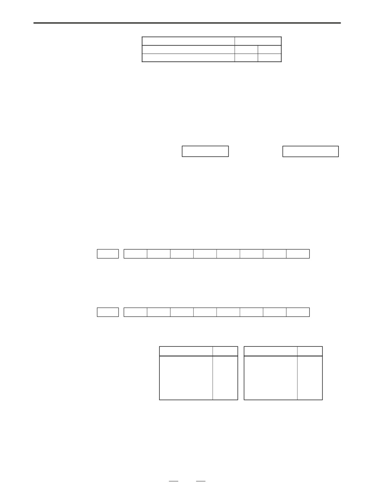
Signal
End state
Finish signal
0
1
store signal
0
1
b. Travel command is being
CNC is reading an axis command (X,Y,Z,...) in a program and giving the
executed
command to the axis.
c. A dwell command is
CNC is reading a dwell command (G04) in a program and is executing
being executed
the dwell command.
d. In-position check
Positioning (G00) to a specified position of a specified axis is not
(confirming positioning)
completed.
is being done
Whether positioning is completed or not is checked as the servo position
error amount. Check it CNC’s diagnostic function as follows:
DGN no.300
Position Error
> PARAM 1826
In-position width
Position error amount almost becomes 0, when positioning of an axis
completes and when the amount becomes within the in-posiiton width,
it is assumed that positioning completes and the next block is exected.
If position error amount does not become within the in-position width,
refer to servo alarm 400, 4n0 and 4n1.
e. Feedrate override is at
Actual feedrate is overridden by the override signals to a programmed
0%
feedrate. Check the override signals using the PMC’s diagnostic function
(PMCDGN).
<Normal override signal>
#7
#6
#5
#4
#3
#2
#1
#0
G0012
*FV7
*FV6
*FV5
*FV4
*FV3
*FV2
*FV1
*FV0
*FVn
:Feedrate override
<2nd override signal (option)>
Feed rate is overridden more finely using the signals below:
See MTB’s manual whether this feature is equipped.
#7
#6
#5
#4
#3
#2
#1
#0
G0013
*AFV7
*AFV6
*AFV5
*AFV4
*AFV3
*AFV2
*AFV1
*AFV0
*AFVn
:2nd feed rate override
<State of override signal>
*FV7@@@@@@@*FV0
*AFV7@@@@@@*AFV0
11 1 1 1 1 1 1
0%
11 1 1 1 1 1 1
0%
11 1 1 1 1 1 0
1%
11 1 1 1 1 1 0
1%
:
:
:
:
10 0 1 1 0 1 1
100%
10 0 1 1 0 1 1
100%
:
:
:
:
00 0 0 0 0 0 1
254%
00 0 0 0 0 0 1
254%
00 0 0 0 0 0 0
0%
00 0 0 0 0 0 0
0%
320
B-63005EN/01
7.TROUBLESHOOTING
f.
Interlock signal or start
<T series only>
lock signal is input
Start lock signal is input
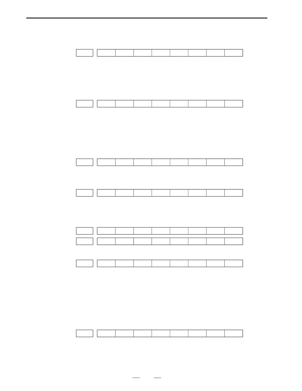
#7
#6
#5
#4
#3
#2
#1
#0
G0007
STLK
#1 (STLK)
With this signal being 1, start lock signal is input.
<Common to T series and M series>
There are a plural number of interlock functions. Parameters are set by
machine tool builders for which interlock function is used.
Therefore, confirm the following parameters at first:
#7
#6
#5
#4
#3
#2
#1
#0
3003
DIT
ITX
ITL
#0 (ITL)
0 : Interlock signal(*IT) is valid.
#2 (ITX)
0 : Interlock signal (*ITn) is valid.
#3 (DIT)
0 : Interlock signal ("MITn) is valid.
Confirm which interlock signal is activated by the PMC’s diagnostic
function (PMCDGN) .
1) Interlock signal (*IT) is input
#7
#6
#5
#4
#3
#2
#1
#0
G0008
*IT
#0 (*IT)
: When this bit is 0, interlock signal is input.
2) Interlock signal per each axis (*ITn) is input
#7
#6
#5
#4
#3
#2
#1
#0
G0130
*IT8
*IT7
*IT6
*IT5
*IT4
*IT3
*IT2
*IT1
*ITn
When the bit is 0, the corresponding axis’s interlock signal is input.
3)
Interlock signal per axis and direction(+/- MITn) is input
⋅ M series
#7
#6
#5
#4
#3
#2
#1
#0
G0132
+MIT4
+MIT3
+MIT2
+MIT1
G0134
-MIT4
-MIT3
-MIT2
-MIT1
⋅ T series
#7
#6
#5
#4
#3
#2
#1
#0
X0004
-MIT2
+MIT2
-MIT1
+MIT1
"MITn=1 shows interlock signal per axis and direction is input.
* For the T series, "MITn is valid only for manual operation.
4)
Controlled axis detach function is running. A detached axis
is
specified for travelling.
*This function is valid when CNC parameter No.1005#7=1. For
whether this function is running or not, confirm the following signal
using PMC’s diagnostic function
(PMCDGN). Check the axis
concerned.
#7
#6
#5
#4
#3
#2
#1
#0
F0110
MDTCH8
MDTCH7
MDTCH6
MDTCH5
MDTCH4
MDTCH3
MDTCH2
MDTCH1
When signal MDTHn is “1” ,the axis detach function is in valid.
The control axis detach function becomes valid by the following
signal issued from the PMC or a CNC side parameter. Check as in the
following procedure :
321
7. TROUBLESHOOTING
B-63005EN/01
1) The control axis detach signal (DTCHn) is input.
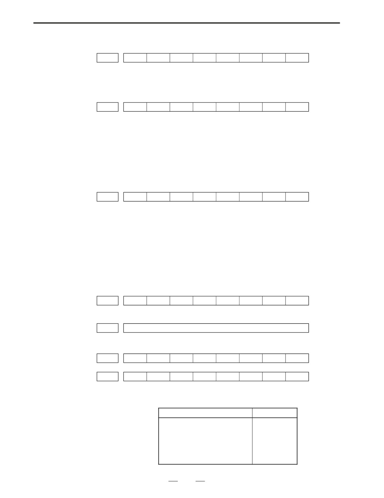
#7
#6
#5
#4
#3
#2
#1
#0
G0124
DTCH8
DTCH7
DTCH6
DTCH5
DTCH4
DTCH3
DTCH2
DTCH1
If it is 1, the corresponding axis is detached.
2) The following parameter enables the control axis detach function to
the corresponding axis.
#7
#6
#5
#4
#3
#2
#1
#0
0012
RMVx
#7(RMVx)0 : Controlled axis is connected
1 : Controlled axis is detached
g. CNC is waiting for
Actual spindle speed does not arrive at a speed specified in a program.
spindle speed arrival
Confirm the signal state using the PMC’s diagnostic function
signal to be input
(PMCDGN).
#7
#6
#5
#4
#3
#2
#1
#0
G0029
SAR
#4(SAR) : When this signal is 0, spindle speed does not arrive at the specified speed.
This function is valid when PARAM 3708#0=1.
h. Manual feedrate override
Normally manual feedrate override function is used for jog feed.
is 0% (dry run)
But when DRN(dry run) signal turns on during an auomatic
operation,override values set with these signals become valid to the
following speed set by a parameter.
#7
#6
#5
#4
#3
#2
#1
#0
G0046
DRN
#7(DRN) : Dry run signal is input with this signal being 1.
1410
Dry run rate
The rate when the following override value is 100%.
#7
#6
#5
#4
#3
#2
#1
#0
G0010
*JV7
*JV6
*JV5
*JV4
+JV3
*JV2
*JV1
*JV0
↓
↓
↓
G0011
*JV15
*JV14
*JV13
*JV12
+JV11
*JV10
*JV9
*JV8
When override value is 0%, all bits of the above address is
[1111
1111] or [0000
. . . . 0000].
*JV15 .
JV0
Override
1111 1111 1111 1111
0.00%
1111 1111 1111 1110
0.01%
:
1101 1000 1110 1111
100.00%
:
0000 0000 0000 0001
655.34%
0000 0000 0000 0000
0.00%
322
B-63005EN/01
7.TROUBLESHOOTING
i. NC is in a reset state
In this case, the CNC’s status display shows RESET. Refer to item 1.
(2) Only rapid traverse in positioning (G00) does not function Confirm
the following parameter and signals from the PMC.
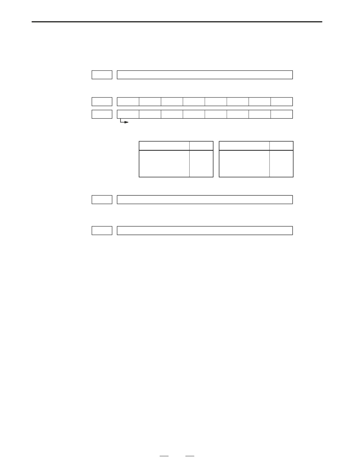
(a) Setting value of rapid traverse rate
1420
Rapid traverse rate per axis
(b) Rapid traverse override signals
#7
#6
#5
#4
#3
#2
#1
#0
G0014
ROV2
ROV1
G0096
HROV
*HROV6
*HROV5
*HROV4
*HROV3
*HROV2
*HROV1
*HROV0
(HROV-0)
(HROV=1)
ROV1
ROV2
Override
*HROV6
*HROV0
Override
0
0
100%
1 1
1
1
1
1
1
0%
1
1
50%
1 1
1
1
1
1
0
1%
0
1
25%
:
:
1
1
Fo
0 0
1
1
0
1
1
100%
1421
Rapid traverse override F0 rate
(3) Only feed (other than G00) does not function
(a) Maximum feedrate set by parameter is incorrect.
1422
Maximum feedrate
Feedrate is clamped at this upper feedrate.
(b) Feedrate is specified by feed per revolution (mm/rev)
1) Position coder does not rotate
Check the connection between spindle and position coder
The following failure is considered:
⋅
T iming belt is broken
⋅
Key is removed
⋅
Coupling is loose
⋅
Connector of signal cable is loosened
2) Position coder is faulty
(c) Thread cutting does not operate
1) Position coder does not rotate
Check the connection between spindle and position coder
The following failure is considered:
⋅
Timing belt is broken
⋅
Key is removed
⋅
Coupling is loose
⋅
Connector of signal cable is loosened
2) Position coder is faulty
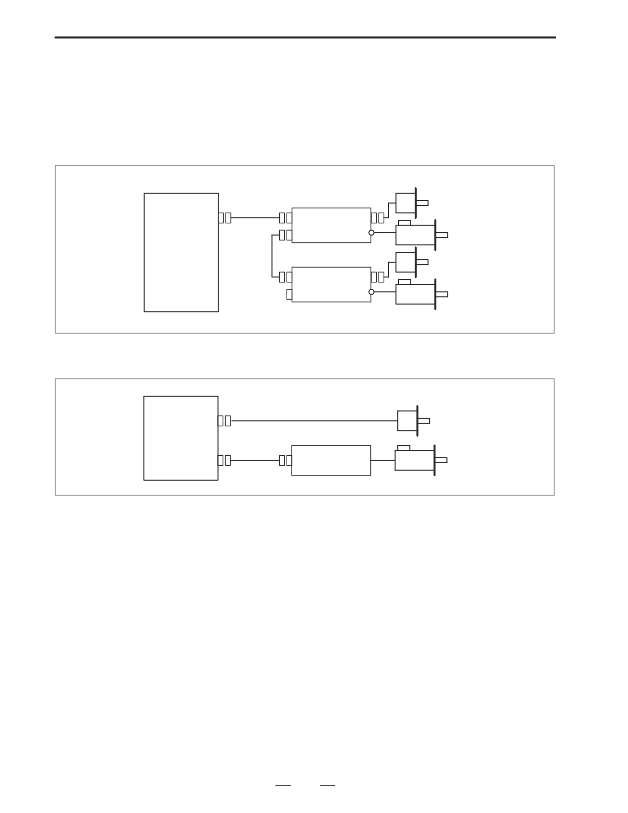
Position coder is connected to the spindle amplifier when serial
interface spindle is used or connected to the CNC when analog
interface spindle is used.
For details of connection, refer to the following.
323
7. TROUBLESHOOTING
B-63005EN/01
<T series>
Whether A/B phase signals from the position coder are read
correctly, can be judged also by the spindle speed display on the
CRT screen (position screen). (However, it is not displayed
when PARAM 3105#2=0).
<α series spindle amplifier>
Position
CNC
coder
JA7B
JY2
JA41
SPM
JA7A
TB2
Spindle
motor
Position
coder
JA7B
JY2
SPM
Spindle
JA7A
TB2
motor
<Analog interface spindle amplifier>
CNC
JA41
Position
coder
Analog spindle
Spindle
JA40
amplifier
motor
324
B-63005EN/01
7.TROUBLESHOOTING
7.6
CYCLE START LED
SIGNAL HAS TURNED
OFF
Points
(1) After cycle operation is started, then stopped, check as follows:
(2) Confirm cycle start LED on machine operator’s panel.
(3) Confirm CNC’s diagnostic function.
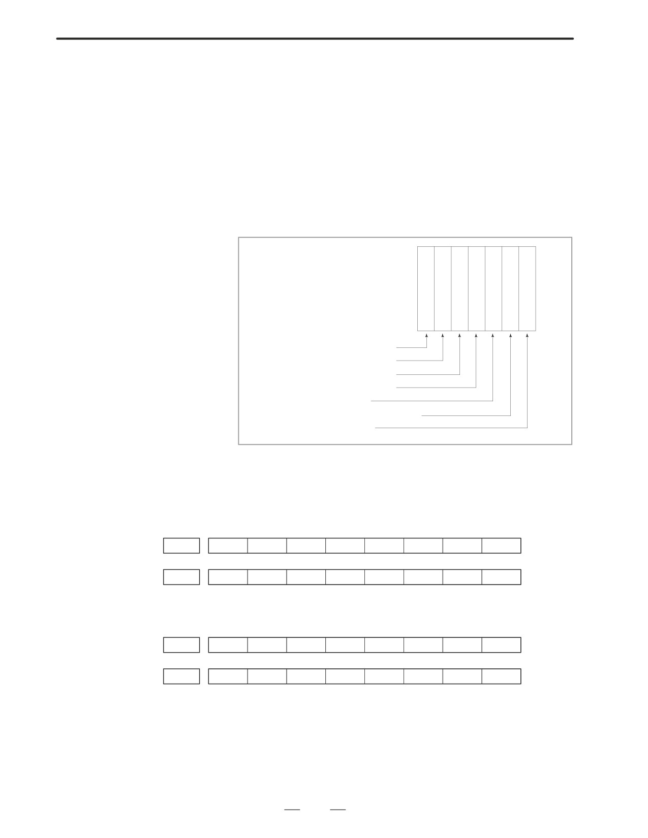
Causes and Remedies
The reason why cycle start LED signal (STL) has turned off are displayed
on CNC’s diagnostic numbers 020 to 025 as follows:
020 CUT SPEED UP/DOWN
1
0
0
0
1
0
0
021 RESET BUTTON ON 0
0
1
0
0
0
0
022 RESET AND REWIND ON
0
0
0
1
0
0
0
023 EMERGENCY STOP ON
1
0
0
0
0
0
0
024 RESET ON
1
1
1
1
0
0
0
025 STOP MOTION OR DWELL
1
1
1
1
1
1
0
a. Emergency stop signal
b. External reset signal
c. Reset button on MDI
d. Reset & rewind signal
e. Servo alarm
f.
Feed hold by switching mode
g. Single block stop
Details of signals a to g are as follows:
Confirm the signals concerned using diagnostic function (PMCDGN).
a. Emergency stop is input
1) When I/O card is used :
#7
#6
#5
#4
#3
#2
#1
#0
X1008
*ESP
#7
#6
#5
#4
#3
#2
#1
#0
G0008
*ESP
*ESP=0
: Emergency stop signal is input :
2) When I/O card is not used:
#7
#6
#5
#4
#3
#2
#1
#0
X0008
*ESP
#7
#6
#5
#4
#3
#2
#1
#0
G0008
*ESP
*ESP=0
: Emergency stop signal is input :
325
7. TROUBLESHOOTING
B-63005EN/01
b. External reset signal is
input
#7
#6
#5
#4
#3
#2
#1
#0
G0008
ERS
#7(ERS) :
When the bit is 1, external reset signal is input.
This signal is usually used for a confirmation signal of M02 when an M02
is specified in a program as the end of a program.
Therefore, when M02 is executed, this signal is input.
c. Reset button on the MDI
An automatic operation is put into a reset status when RESET key on the
is pressed
MDI panel is pressed.
d. Reset & rewind signal is
input
#7
#6
#5
#4
#3
#2
#1
#0
G0008
RRW
#6(RRW) :
When this signal is 1, the reset & rewind signal is input.
This signal is usually used for a confirmation signal of M30 when an M30
is specified in a program as the end of a program.
Therefore, when M30 is executed, this signal is input.
e. Servo alarm has
When any servo alarm has generated, cycle operation is put into the reset
generated
state and operation stop.
f.
Cycle operation is in a
The cycle operation becomes feed hold state in the following cases:
feed hold state
1) Modes are switched from an automatic operation mode to a manual
operation mode.
2) Feed hold signal is input.
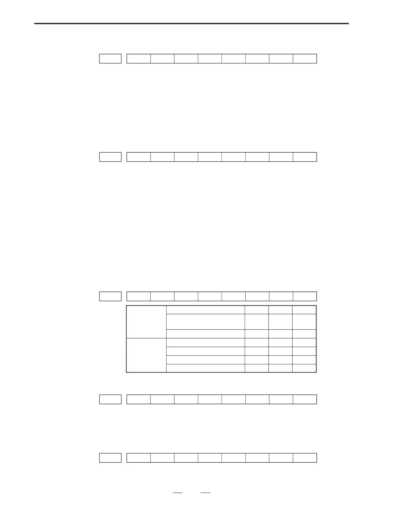
<Mode select signal>
#7
#6
#5
#4
#3
#2
#1
#0
G0043
MD4
MD2
MD1
memory edit(EDIT)
0
1
1
Automatic
Automatic operation
0
0
1
operation
(AUTO)
Manual data input (MDI)
0
0
0
Jog feed (JOG)
1
0
0
Manual
Handle/step
1
0
1
operation
TEACH IN HANDLE
1
1
1
TEACH IN JOG
1
1
0
<Feed hold signal>
#7
#6
#5
#4
#3
#2
#1
#0
G0008
*SP
#5(*SP) : When this signal is 0, the feed hold signal is input.
g. It become single block
stop during automatic
operation
#7
#6
#5
#4
#3
#2
#1
#0
G0046
SBK
#1(SBK) When this signal is 1, the single block signal is input.
326
B-63005EN/01
7.TROUBLESHOOTING
7.7
NO DISPLAY
APPEARS AT
POWER-UP
Points
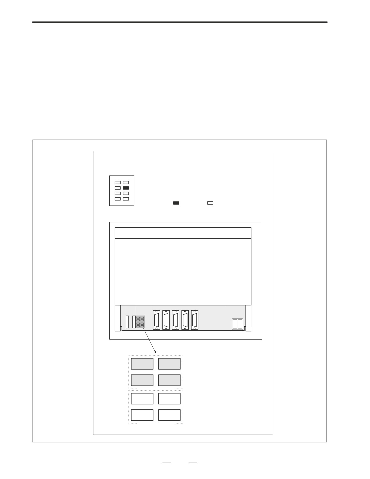
Check whether this problem is caused by (1) a trouble in the display
system or (2) a system failure.
Determining the point
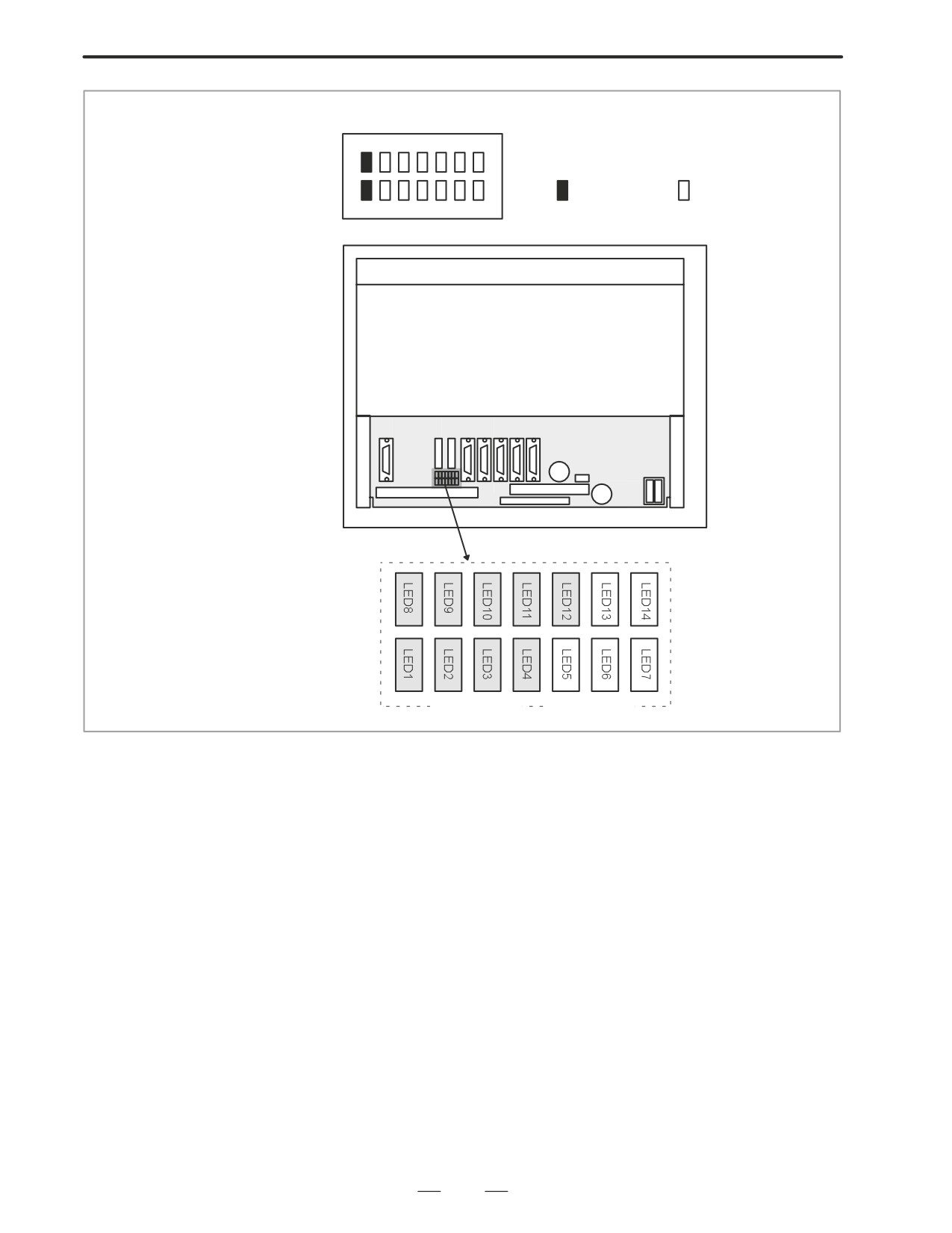
Check that the LEDs on the motherboard are in the status shown below.
For Series 16i/18i
(
:On
:Off )
Rear of the unit
JD36A
CA55
CA54
CP1A
CP1B
LED
LED1
LED2
LED3
LED4
STATUS (green)
SERVO
SYSEMG
SYSFAIL
PARITY
ALARM (orange)
327
7. TROUBLESHOOTING
B-63005EN/01
For Series 160i/180i with a personal computer function
(
: On
: Off
)
LED positions
Rear of the unit
JD33
CA54
CA55
LED
STATUS(green)
ALARM (orange)
If the LED status indicated above is observed, the system operates
normally. In this case, there is a trouble in the display system.
If the LEDs are not in the status indicated above, there is a trouble in
hardware other than the display system.
Causes and
countermeasures
1. When the display system
(1) Check the following:
is in trouble
1) Is the power cable of the backlight connected?
2) Is the video signal cable connected? Is there cable breakage or poor
contact?
(2) Causes and remedies
When nothing is displayed
1) The power supply to the display is faulty.
(Replace the
motherboard or inverter PC board.)
2) The display is faulty.
2. When the system is in
When the LEDs on the motherboard are not in the status indicated in
trouble
”Determining the point” given previously, the motherboard or display
control card may be faulty.
328
B-63005EN/01
7.TROUBLESHOOTING
7.8
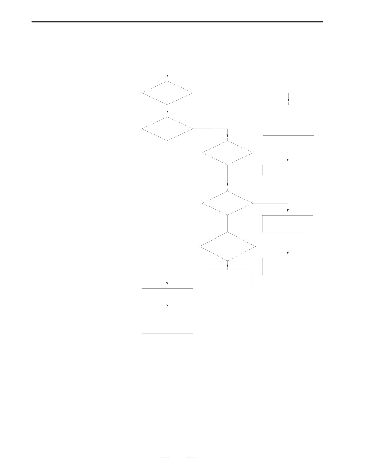
ALARM 85 TO 87
(READER/PUNCHER
(START)
INTERFACE ALARM)
YES
Alarm 85?
NO
· Check baud rate
and other I/O pa
rameters
YES
· I/O device is
Alarm 86?
faulty
NO
Is I/O
NO
parameter
correct?
YES
Set correct parameters
OFF
Is power of I/O ?
ON
Turn on I/O device
Is cable
NO
connection right?
YES
Connect the cable
· I/O device is faulty
· I/O interface
module is faulty
Alarm 87
· I/O device is faulty
· I/O interface mod
ule is faulty
Causes
(a) Parameters on reader/puncher interface are not correct.
Check the following setting data and parameters.
(b) External I/O device or host computer is faulty.
(c) I/O board is faulty.
(d) Cable between NC and I/O device is faulty.
Countermeasures
(a) Parameters on reader/puncher interface are not correct.
Check the following setting data and parameters:
<Setting>
PUNCH CODE=0 OR 1 (0: EIA,1:ISO)
Select ISO or EIA according to the type of I/O device.
If punch code does not match, alarm 86 will generate.
329
7. TROUBLESHOOTING
B-63005EN/01
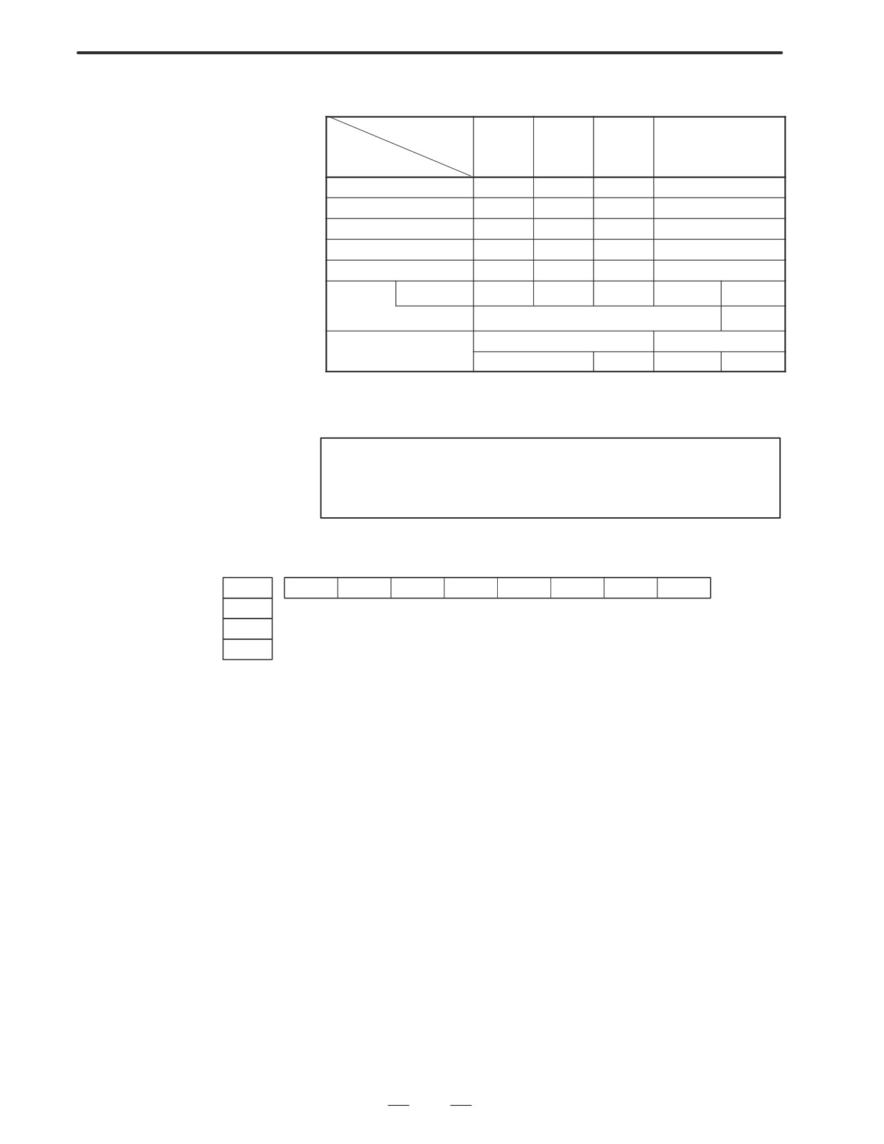
<Parameter>
Value of parame-
ter 0020
0
1
2
3
Function
Feed
0101#7
0111#7
0121#7
0131#7
Data input code
0101#3
0111#3
0121#3
0131#3
Stop bit
0101#0
0111#0
0121#0
0131#0
Type of I/O device
102
112
122
132
Baud rate
103
113
123
133
Commu-
0135#3
-
-
-
0
1
nication
method
RS-232C
RS-422
MAIN CPU BOARD
OPTION-1 BOARD
Connector
JD5A
JD5B
JD5C
JD6A
Numbers in the table indicate parameters and bit numbers.
Example)
101#7:bit7 of parameter 101.
NOTE
For data communications by RS-422, refer to parameters
134 and 135.
#7
#6
#5
#4
#3
#2
#1
#0
0101
NFD
ASI
SB2
0111
0121
0131
#7(NFD)
0 : Feed is output before and after data in data output (FANUC PPR)
1 : Feed is not output (standard).
#3(ASI)
0 : Data input code is EIA or ISO (automatic recognition)
1 : Data input code is ASCII.
#0(SB2)
0 : No. of stop bits is 1.
1 : No. of stop bits is 2.
330
B-63005EN/01
7.TROUBLESHOOTING
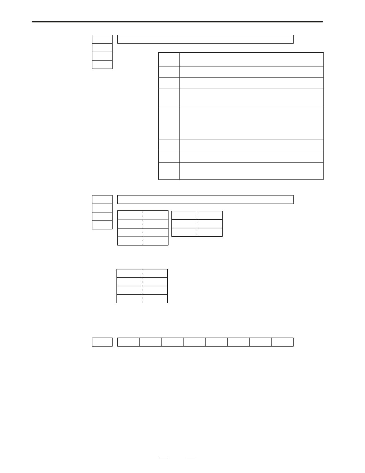
0102
Type of I/O device
0112
0122
Value
TYPE OF I/O DEVICE
0132
0
RS-232-C (control codes DC1 to DC4 are used)
1
FANUC CASSETTE B1/B2 (bubble cassette)
2
FANUC CASSETTE F1 (Old type FLOPPY CASSETTE ADAP-
TOR)
3
FANUC PROGRAM FILE Mate,
FANUC FA CARD ADAPTOR
FANUC FLOPPY CASSETTE ADAPTOR,
FANUC SYSTEM P-MODEL H,
FANUC Handy File
4
Not used
5
Portable tape reader
6
FANUC PPR, FANUC SYSTEM P-MODEL G,
FANUC SYSTEM P-MODEL H
0103
Baud rete
0113
0123
Value
Baud rate
10
4800
0133
7
600
11
9600
8
1200
12
19200
9
2400
When bit#3 of parameter no. 0135=1 (RS-422 interface), the following
setting is also available.
Value
Baud rate
13
38400
14
76800
15
86400
Check the following parameters also, when parameter no.0020 is 3.
#7
#6
#5
#4
#3
#2
#1
#0
0134
CLK
NCD
SYN
PRY
#5(CLK)
0 : Internal clock is used for baud rate clock of RS-422 interface.
1 : External clock is used for baud rate clock of RS-422 interface.
#4(NCD)
0 : CD (signal quality detection) of RS-232C interface is checked.
1 : CD (signal quality detection) of RS-232C interface is not checked.
#2(SYN)
0 : In protocol B, NC reset/alarm is not informed to the host.
1 : In protocol B, NC reset/alarm is informed to the host by SYN and
NAK code.
#1(PRY)
0 : No parity bit
1 : With parity bit
331

7. TROUBLESHOOTING
B-63005EN/01
#7
#6
#5
#4
#3
#2
#1
#0
0135
RMS
R42
PRA
ETX
ASC
#7(RMS) In protocol A, status of remote / tape operation of SAT command is
0 : Always transmitted by 0.
1 : Transmitted by the contents of remote / tape switching request issued
by SET command from the CNC.
#3(R42)
0 : Interface is of RS-232C.
1 : Interface is of RS-422.
#2(PRA)
0 : Communication protocol is protocol A
1 : Communication protocol is protocol B
#1(ETX)
0 : End code of protocol A or extended protocol A is CR of ASCII/ISO.
1 : End code of protocol A or extended protocol A is ETX of ASCII/ISO.
#0(ASC)
0 : All the communication codes except for NC data is ISO code.
1 : All the communication codes except for NC data is ASCII code.
(b) External I/O device or Host computer is in trouble
(i)
Check whether the setting on communication of external I/O
device or host computer is the same as that of the CNC. (baud
rate, stop bits,etc.) If they are not the same, change the setting.
(ii)
When spare I/O device presents, check whether it is possible to
realize communication using the spare I/O device.
332
B-63005EN/01
7.TROUBLESHOOTING
(c) Spindle module or communication control module is faulty
(i)
When parameter no.0020 is 0 or 1 or 2 (JD36A,JD36B of Main
CPU board) Replace the module since spindle module may be
faulty.
(ii)
When parameter no. 0020 is 3 (JD28A,JD6A of option 1 board)
Because communication control module (5) may be faulty,
replace the module.
(d) Cable between NC and I/O device is faulty.
Check the cable for disconnection or wrong connection.
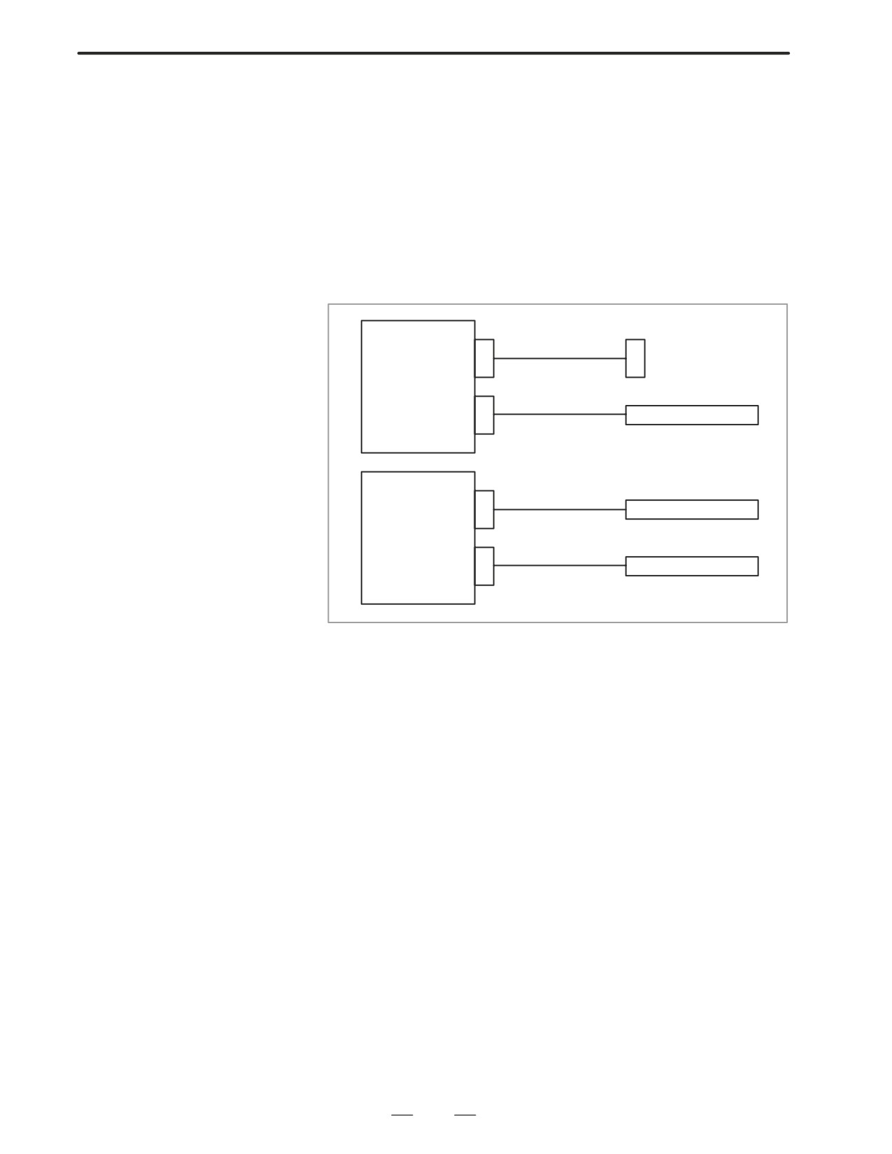
<Connection>
Mother board
R232C(JD36A)
Punch panel
R232C(JD36B)
Tape reader
Serial
communication
R232C(JD28A)
Host computer
R232C(JD6A)
Host computer
333
7. TROUBLESHOOTING
B-63005EN/01
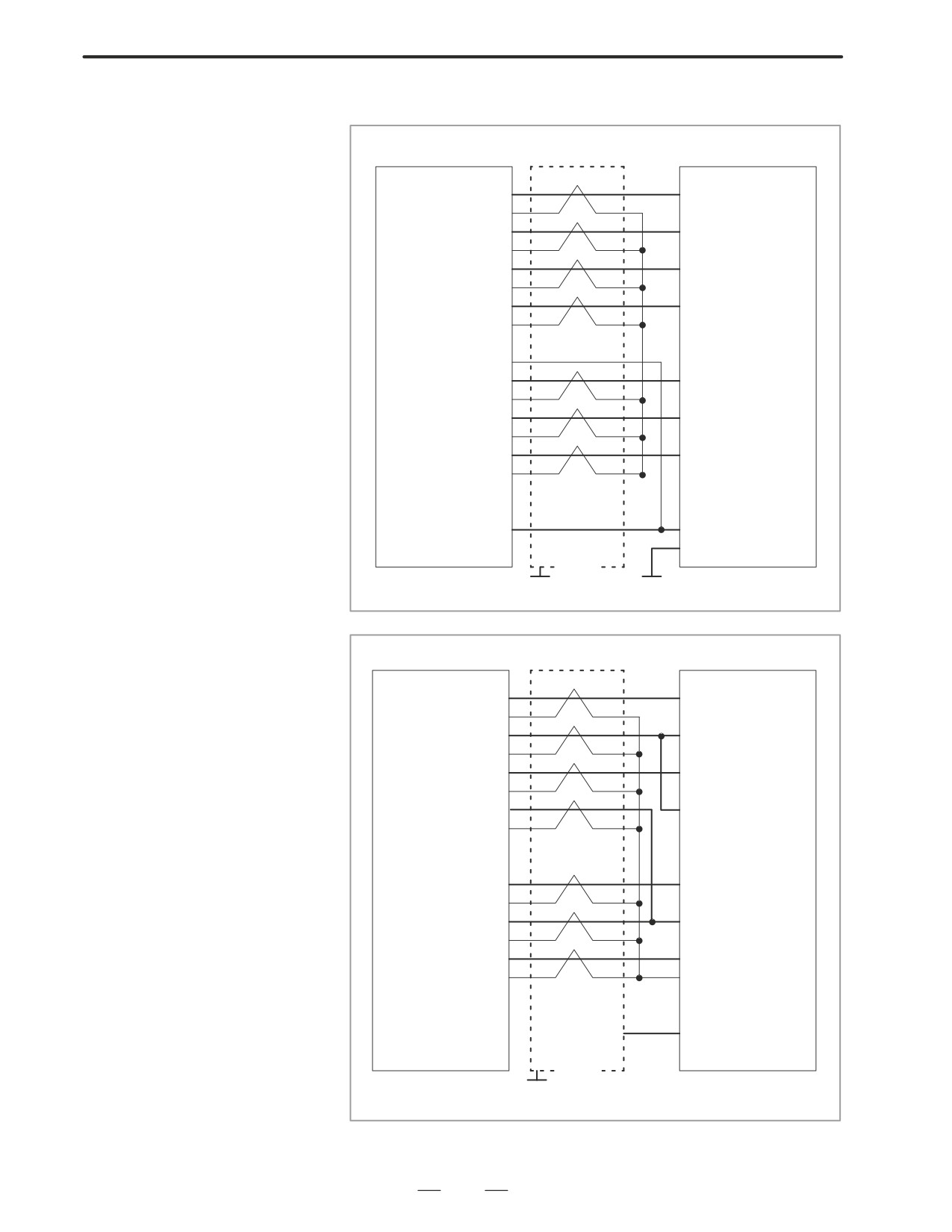
< Cable connection>
R232C
(JD36A)
Punch panel
R232C
(JD36B)
RD
(01)
(03) RD
0V
(02)
DR
(03)
(06) DR
0V
(04)
CS
(05)
(05) CS
0V
(06)
CD
(07)
(08) CD
0V
(08)
(09)
+24V (10)
SD
(11)
(02) SD
0V
(12)
ER
(13)
(20) ER
0V
(14)
RS
(15)
(04) RS
0V
(16)
(07) SG
(17)
(18)
+24V (19)
(25) +24V
(20)
(01) FG
Shield
G
G
Connector :DBM-25S
Connector : Half-pitch 20-pins
R232C
(JD28A)
Host computer
RD
(01)
(02) SD
0V
(02)
DR
(03)
(20) ER
0V
(04)
CS
(05)
(04) RS
0V
(06)
CD
(07)
(08) CD
0V
(08)
(09)
+24V (10)
SD
(11)
(03) RD
0V
(12)
ER
(13)
(06) DR
0V
(14)
RS
(15)
(05) CS
0V
(16)
(07) SG
(17)
(18)
+24V (19)
(25) +24V
(20)
(01) FG
Shield
G
Connector D-SUB 25 pins
Connector : Half-pitch 20-pins
334
B-63005EN/01
7.TROUBLESHOOTING
CAUTION
1
When CS is not used, connect it to RS.
2
For protocol A or extended protocol A: When DR is not used,
connect it to ER. Always connect CD to ER.
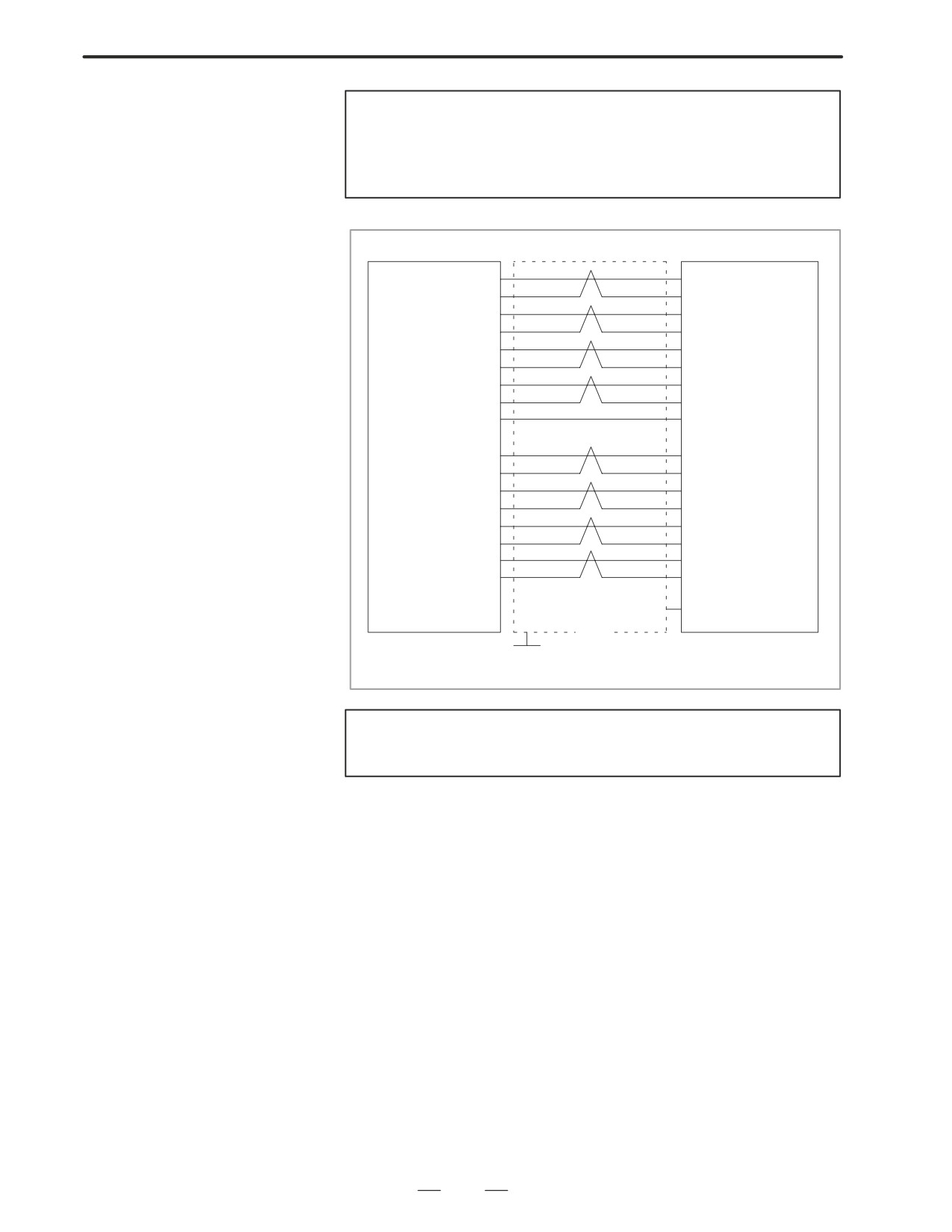
RS422(JD6A)
Host computer
RD (01)
(04) RD
*RD (02)
(22) *RD
RT (03)
(17) TT
*RT (04)
(35) *TT
CS (05)
(07) RS
*CS (06)
(25) *RS
DM (07)
(12)
TR
Note) *DM (09)
(30) *TR
0V (08)
(19) SG
(+24V) (10)
SD (11)
(06) RD
*SD (12)
(24) *RD
TT (13)
(08) RT
*TT (14)
(26) *RT
RS (15)
(09) CS
*RS (16)
(27) *CS
TR (17)
(11) DM
*TR (18)
(29) *DM
(+24V) (19)
(20)
(01) FG
Shield
G
Connector : Half-pitch 20 pins (PCR)
Connector : D-SUB 25 pins
CAUTION
Always use a twisted pair cable.
335
7. TROUBLESHOOTING
B-63005EN/01
7.9
ALARM 90
(REFERENCE
POSITION RETURN IS
ABNORMAL)
Contents
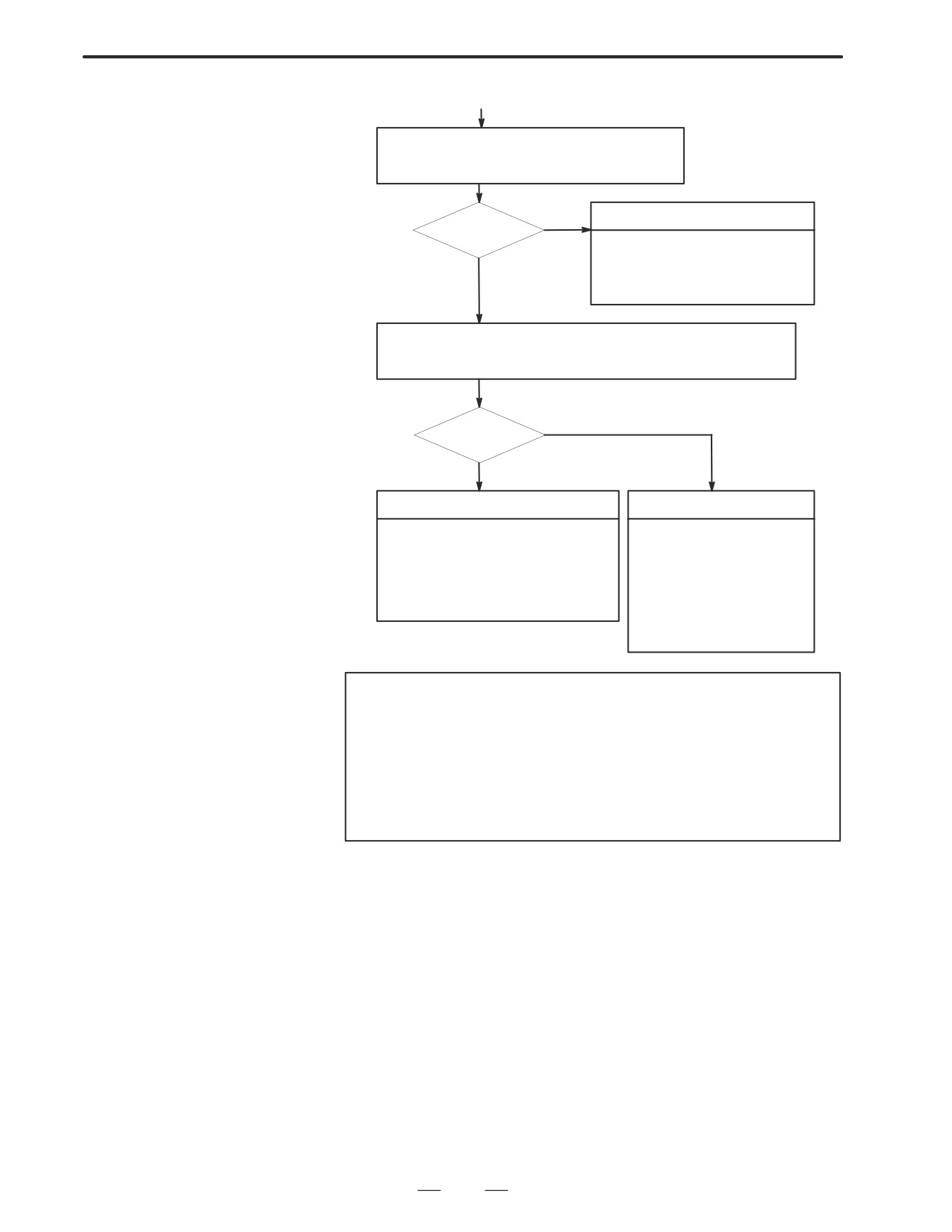
Reference position return was executed when the following condition is
not satisfied:
The CNC received one rotation signal at least one time when the axis is
moving to the reference position at a speed higher than a speed equivalent
to 128 pulses of position error amount(DGN300).
Countermeasures
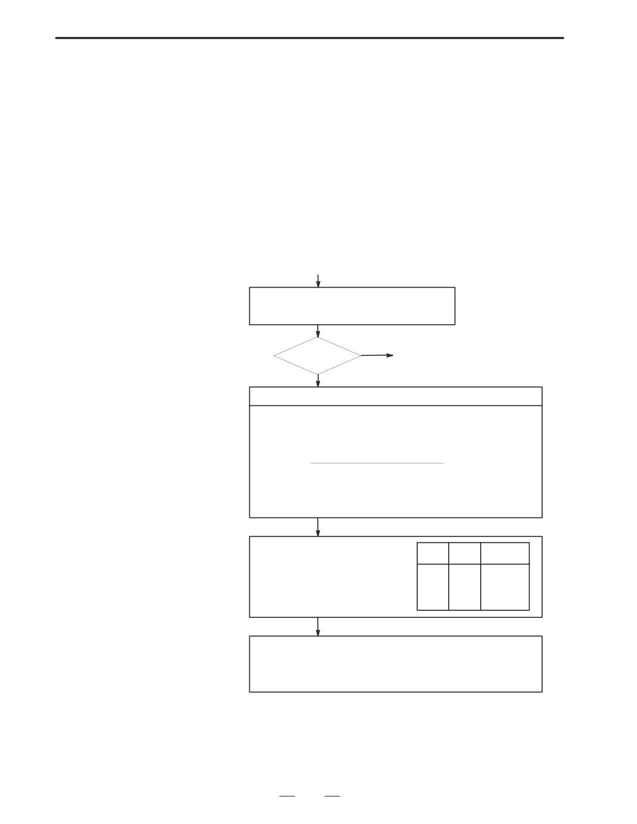
(START)
Position error
Check whether position gain is greater than 128 pulses
amount : 300
(DGN 300) before or during reference position return.
YES
128 or more
(1) Next page
NO
Raise the speed
Check feed rate command:
PRM 1420 F : Rapid traverse rate
(mm/min)
PRM 1424
Manual rapid traverse rate (mm/min)
PRM 1825 G : Servo loop gain
(0.01sec-1)
F
5000/3
Position error=
G detection unit[µm/PLUSE]
Detection unit : Move amount to a command pulse (usually 1µm)
In metric machine, if the no. of digits below decimal point is 4 on the position
display screen, detection unit is 0.1 mm.
Check rapid traverse override signals :
ROV1
DGN
014.0
ROV1
ROV2
Override
1014.0 (For TT series)
ROV2
DGN
014.1
0
0
100%
1014.1 (For TT series)
0
1
50%
PRM
1421
Fo rate
1
0
25%
1
1
Fo rate
Check reference position return deceleration signal
DEC1 DEC8 DGN 009.0 ∼ 009.7
When reference position return is started from deceleration signal 0, feed rate
becomes FL rate.
PRM 1425 FL rate
336
B-63005EN/01
7.TROUBLESHOOTING
(1)
Check whether the motor ratated more than one rota-
tion (one rotation signal is issued ) at faster than 128
pulses of position error amount.
NO
Return start position is too close
Rotated ?
· Chagne the return start position.
· Move the machine at faster that 128
YES
pulses for more than one rotation to
wards RP.
Check that voltage of pulse coder is higher than 4.75 V.
To measure pulse coder voltage, remove the motor cover and measure on
pulse coder PCB at across + and - or +5V and 0V terminals.
NO
More than 4.75V
YES
Hardware failure
Pulse coder power voltage is low
· Pulse coder is faulty
· Caused by wire resistance
Change pulse coder or motor
check wire material
· Main CPU board is faulty
(resistance shall be 0.5W or
Change main CPU board
less in both ways to restrict
· Option 2 board is faulty
voltage drop.)
Change option 2 board
· Pulse coder power supply is
abnormal
Change the power supply .
CAUTION
1
After the pulse coder or motor is exchanged, reference
position or machine’s standard point may be different from
former one. Please set it correctly.
2
When the main board is exchanged, all the data stored in
memory is lost. Reset all the NC data again, referring to the
data input/output item.
D Reference
A speed more than 128 pulses is required because if speed is lower that
this, one-rotation signal does not function stably, causing improper
position detection.
If bit 0 of parameter No. 2000 is set to 1, a speed corresponding to a
positional deviation of 1280 pulses or more is required.
Parameter No. 1836 can be set to 128 or less, as the minimum positional
deviation with which reference position return is possible.
(If the
parameter is set to 0, 128 is assumed as the minimum positional deviation.
If bit 0 of parameter No. 2000 is set to 1, a value equal to ten times the
set value is used for checking.)
337
7. TROUBLESHOOTING
B-63005EN/01
Absolute position data in the serial pulse coder was lost.
7.10
(This alarm will be generated when serial pulse coder is exchanged or
ALARM 300
position feedback signal cable of the serial pulse coder is disconnected).
(REQUEST FOR
REFERENCE
POSITION RETURN)
Remedies
Machine position must be memorized using the following method:
D When reference position
(1) Execute manual reference position return only for an axis for which
return function is
this alarm was generated.When manual reference position return
present
cannot be executed because of an another alarm, set parameter 1815#5
to 0 and release the alarm and perform manual operation.
(2) Press RESET key at the end of reference position return to release the
alarm.
D When reference position
Execute dogless reference position setting to memorize the reference
return function is not
position.
present
D When serial pulse coder
Since the reference position is different from the former one, change the
is changed
grid shift value (PRM 1850) to correct the position.
Related parameters
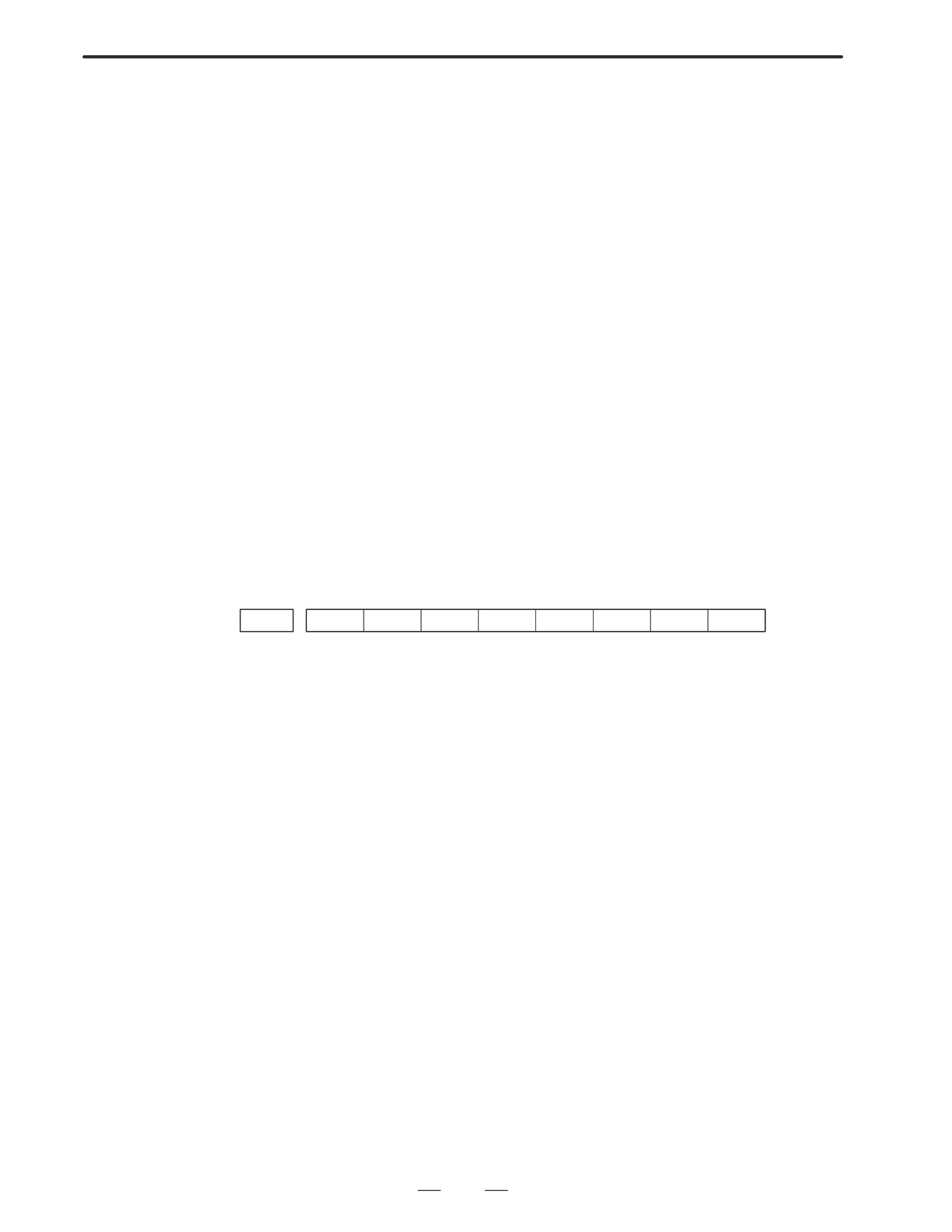
#7
#6
#5
#4
#3
#2
#1
#0
1815
APC x
APZx
#5(APCx)
0 : Position detector is incremental pulse coder.
1 : Position detector is absolute pulse coder.
#4(APZx)
Reference position of absolute pulse coder is :
0 : not established
1 : established
338
B-63005EN/01
7.TROUBLESHOOTING
Digital servo parameters are abnormal.
7.11
(Digital servo parameters are set incorrectly.)
ALARM 417 (DIGITAL
When alarm 315 is occured at the same time, check the cause of alarm 351
SERVO SYSTEM IS
of section 9.16.
ABNORMAL)
D Causes
1
Confirm the setting value of the following parameters:
PRM 2020 : Motor format number
PRM 2022 : Motor rotation direction
PRM 2023 : Number of pulses of velocity feedbacks
PRM 2024 : Number of pulses of position feedback
PRM 1023 : Servo axis number
PRM 2084 : Flexible feed gear ratio
PRM 2085 : Flexible feed gear ratio
Confirm the details with diagnosis function of CNC side.
2
Change the setting of this parameter to 0.
PRM 2047 : Observer parameter
3
Perform initial setting of digital servo parameters.
Refer to setcion 5.1 “Initial Setting of Servo Parameters” .
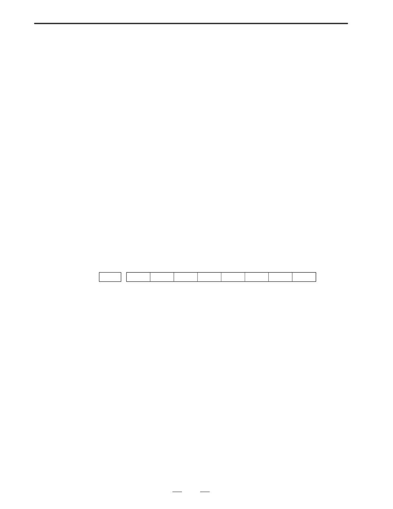
This data indicates the cause of servo alarm No. 417, detected by the NC.
If the alarm is detected by the servo, the PRM bit (bit 4 of DGN No. 0203)
is set to 1.
#7
#6
#5
#4
#3
#2
#1
#0
0280
AXS
DIR
PLS
PLC
MOT
#0(MOT) :
The motor type specified in parameter No. 2020 falls outside the
predetermined range.
#2(PLC) :
The number of velocity feedback pulses per motor revolution, specified in
parameter No. 2023, is zero or less. The value is invalid.
#3(PLS) :
The number of position feedback pulses per motor revolution, specified in
parameter No. 2024, is zero or less. The value is invalid.
#4(DIR) :
The wrong direction of rotation for the motor is specified in parameter No.
2022 (the value is other than 111 or -111).
#6(AXS) :
In parameter No. 1023 (servo axis number), a value that falls outside the
range of 1 to the number of controlled axes is specified. (For example, 4 is
specified instead of
3.)
Alternatively, the values specified in the
parameter are not consecutive.
339
7. TROUBLESHOOTING
B-63005EN/01
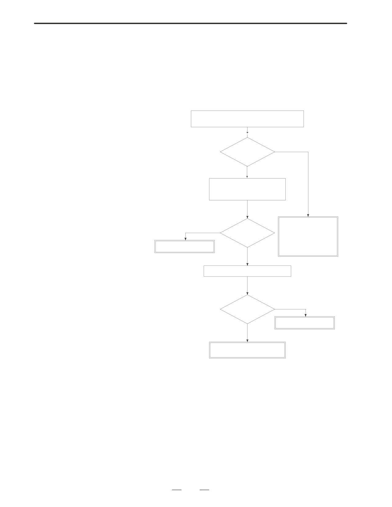
Spindle speed changes abnormally due to load.
7.12
ALARM 704 (SPINDLE
SPEED
FLUCTUATION
DETECTION ALARM)
Remedies
Check whether spindle speed is constant by view
of the speed meter on CRT.
YES
Constant ?
NO
Is a heavy cutting being per-
formed ? Confirm spindle load
on CRT.
Confirm the follow-
ing parameter :
YES
Heavy cutting?
PRM 4911
PRM 4912
PRM 4913
Reduce cutting condition
NO
PRM 4914
Doesn’t the cutting tool worn ?
YES
Worn ?
Replace tool
NO
Spindle servo unit is faulty
Spindle motor is faulty
Remedies
PRM 4911 : A ratio of spindle speed at which actual spindle speed is
regarded as arrived at a command spindle speed.
PRM 4912 : Spindle speed fluctuation ratio up to which the spindle
speed fluctuation detection alarm is not issued.
PRM 4913 : Spindle speed fluctuation that is not regarded as the spindle
speed fluctuation alarm.
PRM 4914 : Time when a spindle speed changed to when spindle speed
fluctuation detection is started.
340
B-63005EN/01
7.TROUBLESHOOTING
Communication error has generated in serial spindle
7.13
ALARM 749
(SERIAL SPINDLE
COMMUNICATION
ERROR)
Causes and Remedies
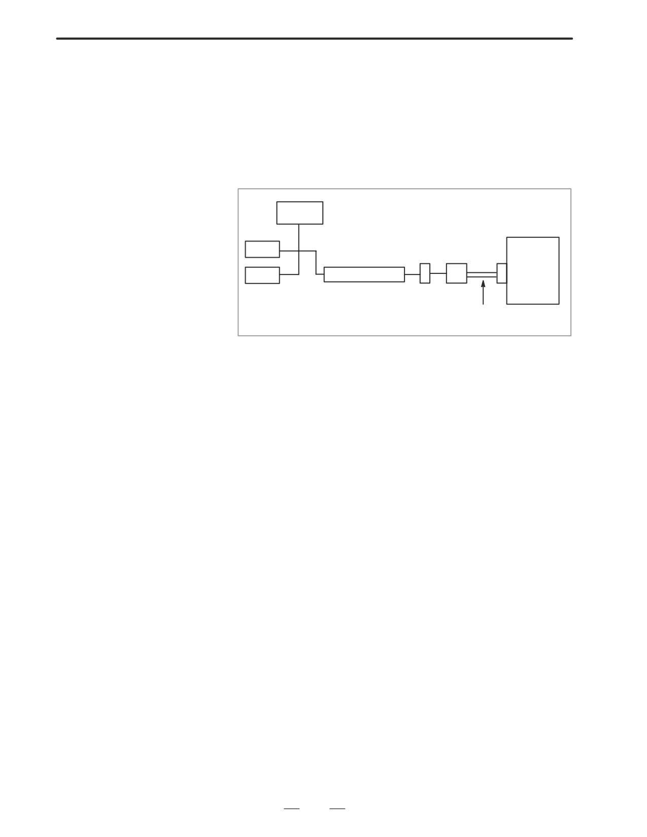
Improper connection between the mother board and the serial spindle.
The following reason is considered.
Main
CPU
ROM
Optical I/O link
adaptor
Spindle
RAM
Spindle control
amplifier
Optical cable
System control module is faulty. (Bold line in the figure below indicates
module mounting position.)
A cable between the mother board and optical I/O link adapter is
disconnected or short-circuited.
Optical I/O link adapter is faulty.
Optical cable is disconnected.
Serial spindle amplifier is faulty.
341
7. TROUBLESHOOTING
B-63005EN/01
When the spindle amplifier does not become normal state immediately
7.14
after power is turned on in the serial spindle system, this alarm is
ALARM 750 (SPINDLE
informed.
SERIAL LINK
CANNOT BE
STARTED)
Points
This alarm does not occur once the system becomes ready including the
spindle system .
This alarm occurs during power on sequence before the system becomes
ready.
After the system becomes ready, serial spindle alarm is issued by alarm
749.
Causes
(1) Optical cable is in poor contact or spindle amplifier power is off.
(2) When display of spindle amplifier shows SU-01 or an alarm other than
AL-24 is displayed, power to the NC is turned on.
In this case, this alarm usually occurs when the NC’s power is turned
off while the serial spindle is operating. Turn off the power of serial
spindle once, then turn it on and starts the system.
(3) Combination of hardware is wrong.
(4) When the 2nd spindle is at the state of (1) to (3).
When the 2nd spindle is used, parameter is set as follows :
Bit 4 of parameter no.3701 is 1: No. of serial spindles connected is 2.
Details of Alarms
Confirm the details of troubles on diagnostic 409.
#7
#6
#5
#4
#3
#2
#1
#0
DGN
0409
SPE
S2E
S1E
SHE
#3(SPE)
0 : In spindle serial control, the serial spindle parameters satisfies the
starting conditions for spindle amplifier.
1 : In spindle serial control, the serial spindle parameters do not satisfy
the starting conditions for spindle amplifier.
#2(S2E)
0 : At the start of spindle serial control, the spindle is normal.
1 : At the start of spindle serial control, the spindle is abnormal.
#1(S1E)
0 : The serial communication module of the CNC side is normal.
1 : The serial communication module of the CNC side is abnormal.
#0(SPE)
0 : Serial communication module on the CNC side is normal.
1 : Serial communication module was detected to be abnormal on the
CNC side.
342
B-63005EN/01
7.TROUBLESHOOTING
Remedies
Reform the following countermeasures based on the above
configurations:
(1) #3(SPE)1: In spindle serial control, the serial spindle parameters does
not satisfy the starting conditions for spindle amplifier.
↓
Confirm the settings of parameters 4000s.
Especially checks the parameters those are changed from the standard
parameters.
(2) #2(S2E)1: At the start of spindle serial control, when an abnormality
is found in the 2nd spindle side.
↓
Check the 2nd spindle parameters and connections to see whether the
spindle is mechanically and electronically connected to the spindle.
↓
If the above settings and connections are right, the module of (4) or the
spindle amplifier itself may be defective.
(3) #1(SIE)1: When an abnormality is found in the 1st spindle at the start
of serial spindle control, exchange the unit if the following
check items are not concerned.
↓
Check the parameters and connections at the 1st spindle to see whether
the 1st spindle is mechanically and electrically connected.
↓
If the parameters and connections are correct, the system control
module shown below or the spindle amplifier itself is faulty.
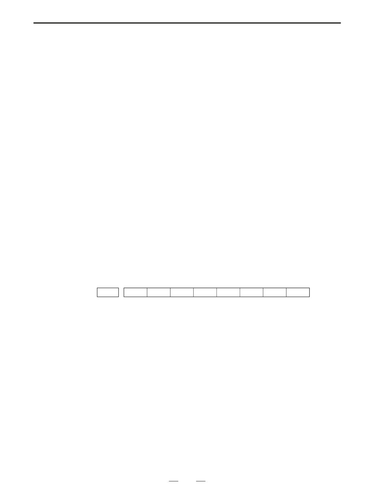
(4) #0(SPE)1: The serial communication module is detected to be
abnormal. Exchange the following module :
343
7. TROUBLESHOOTING
B-63005EN/01
Because an ambient temperature of the control unit becomes high, a
7.15
thermostat mounted on the back panel of NC functions and informs an
ALARM 700
alarm.
(OVERHEAT AT
CONTROL SIDE)
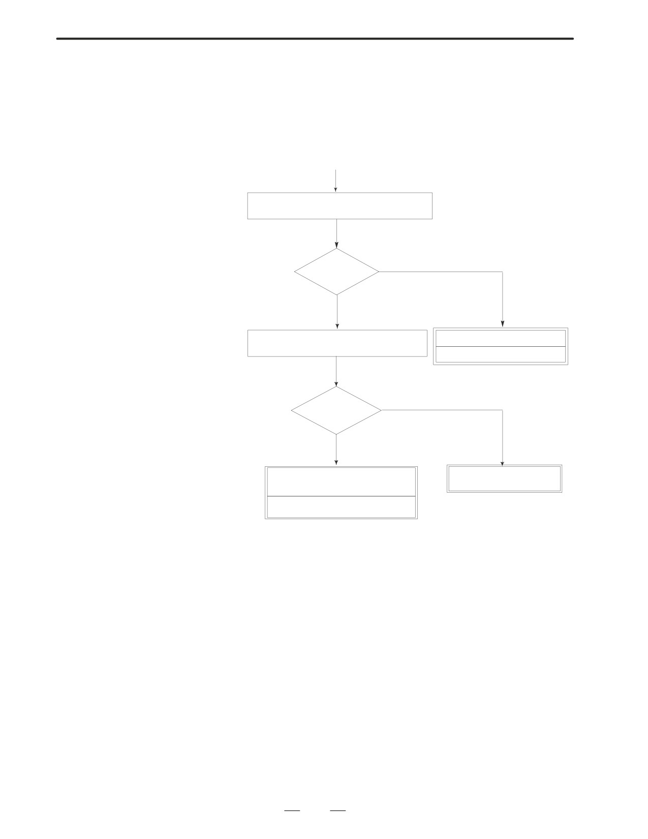
Remedies
(START)
Check fan on the top of the control unit is oper-
ating when power is on.
NO
Operating
YES
Check temperature around the control unit is
Fun motor is faulty
high (more than 45 degrees)
Replace fan motor
YES
High tempera-
ture ?
NO
Thermostat on the back panel of NC
Lower temperature around
is faulty.
the control unit
Replace the back panel of NC.
344
B-63005EN/01
7.TROUBLESHOOTING
ROM parity error occurred.
7.16
ALARM 900 (ROM
PARITY ERROR)
Causes and Remedies
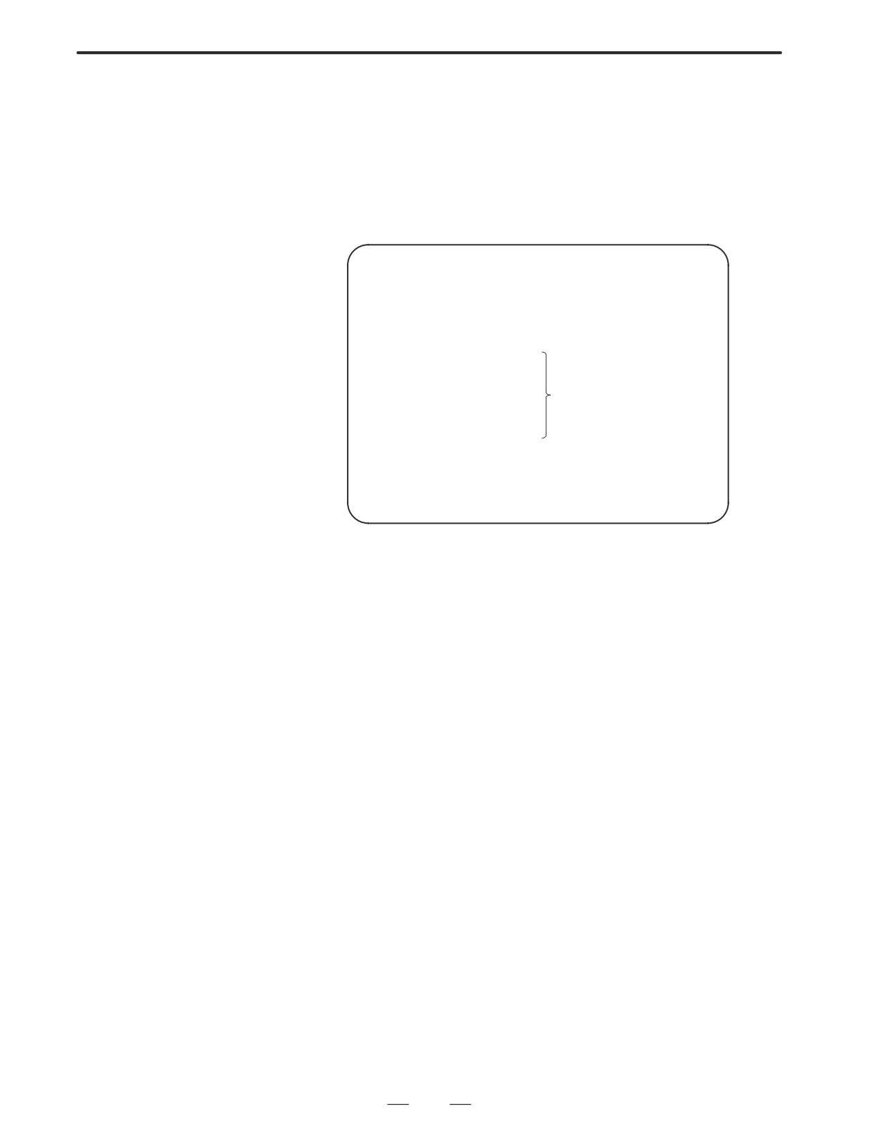
(1) ROM module mounted on the mother board or ROM is defective.
SYSTEM ALARM
B0A1-02
900
ROM PARITY
CNC ROM MODULE : FC0
Defective file
or ROM is displayed
MACRO ROM MODULE
SERVO ROM
Confirm the series and versions of control software those are displayed
on upper right of the screen.
*FROM module may be written data by machine tool builder.
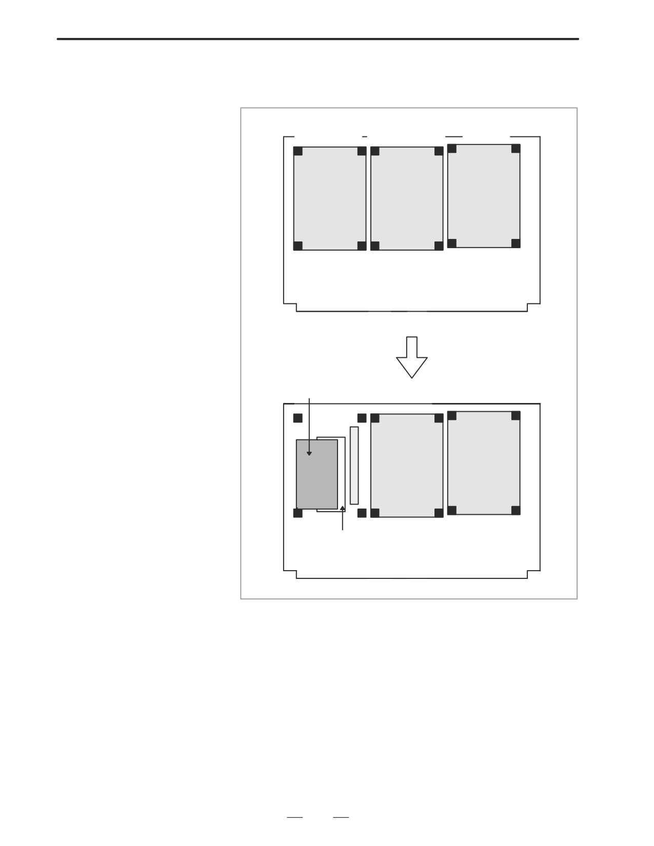
345
7. TROUBLESHOOTING
B-63005EN/01
D Mounting position of the
FROM/ROM module
<Motherboard>
(1)
(2)
(3)
Axis control card
Display control card
CPU card
Motherboard
The FROM module is mounted
below the axis control card.
Remove the axis control card ac-
cording to Section 2.6.
FROM module
Connector
DIMM module socket.
346

B-63005EN/01
7.TROUBLESHOOTING
A parity error occurred in the RAM module for workpieces.
7.17
ALARM 910, 911
(SRAM PARITY
ERROR)
Causes and
countermeasures
D SRAM module is faulty.
If the alarm is issued immediately after the power is turned on, turn off
Stored data is faulty.
the power, then turn it on while holding the
RESET
and
DELETE
keys to clear
all memory contents.
If the parity alarm still exists even after the memory all clear operation,
the SRAM module on the motherboard may be faulty. So, replace the
SRAM module.
D Set all data again according to ”Data Input/Output”.
D Voltage drop in the
A battery alarm is issued if the voltage level drops to 2.6 V or lower when
memory backup battery
the voltage rating is 3.0 V.
When the voltage of the memory backup battery has lowered, ”BAT”
blinks at the bottom of the screen.
When the battery alarm is turned on, replace the battery with a new lithium
battery as soon as possible.
D Replace the battery according to Section 2.9.
D The motherboard is
If the alarm is released by memory all clear operation, the motherboard
faulty.
may also be faulty.
NOTE
1
If an SRAM parity alarm occurs in a module other than the
motherboard, ALM972 NMI OCCURRED IN OTHER
MODULE appears.
2
If a parity alarm occurs in a system that has been kept
switched off for a long time, it is likely that the battery life has
expired or the backup circuit
(on the motherboard) is
defective.
347
7. TROUBLESHOOTING
B-63005EN/01
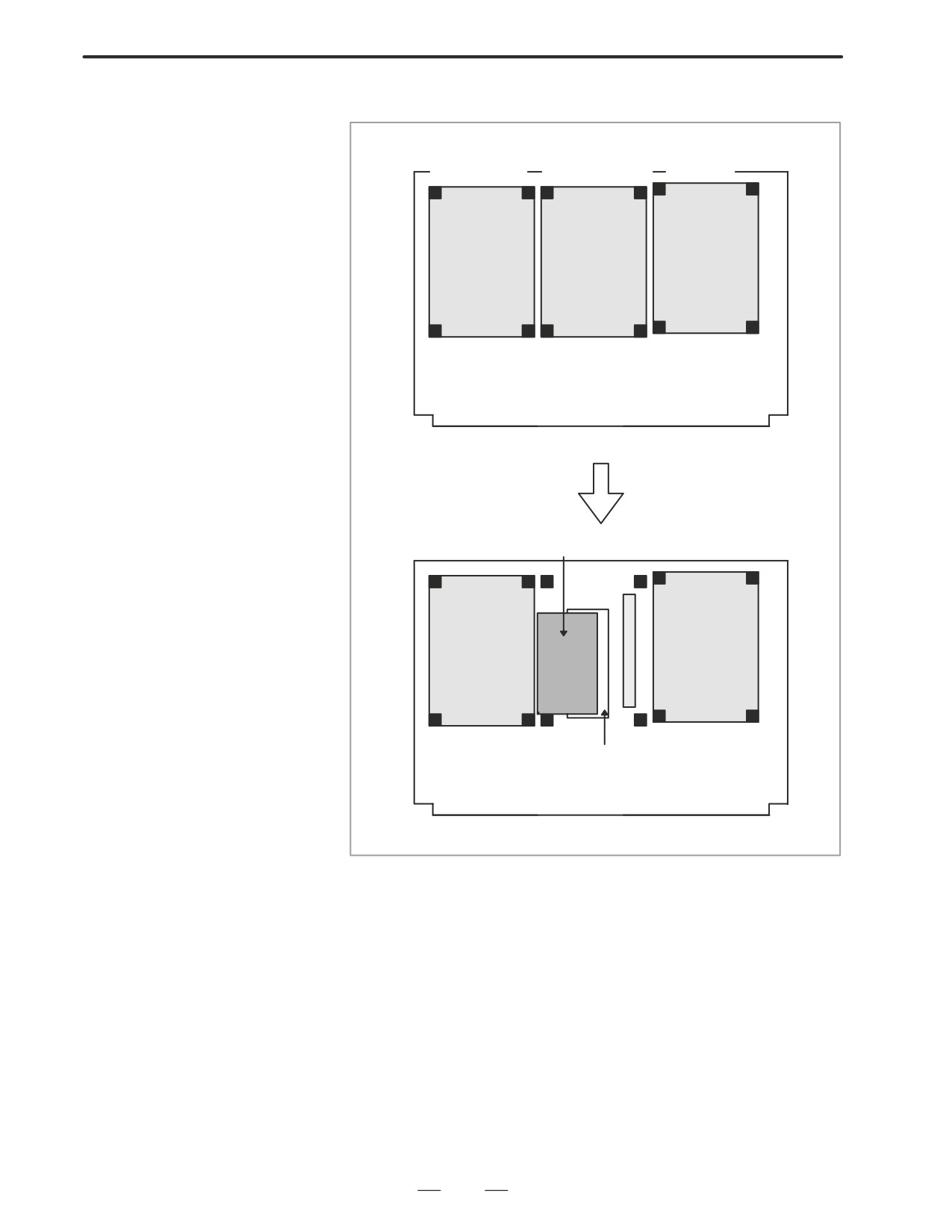
D Mounting position of the
<Motherboard>
SRAM module
(1)
(2)
(3)
Axis control card
Display control card
CPU card
Motherboard
The SRAM module is mounted
below the display control card.
Remove the axis control card ac-
cording to Section 2.6.
SRAM module
Connector
DIMM module socket.
348
B-63005EN/01
7.TROUBLESHOOTING
A parity error occurred in the DRAM module.
7.18
ALARM 912 TO 919
(DRAM PARITY
ERROR)
Cause and
The DRAM module on the CPU card may be faulty. Replace the DRAM
countermeasure
module.
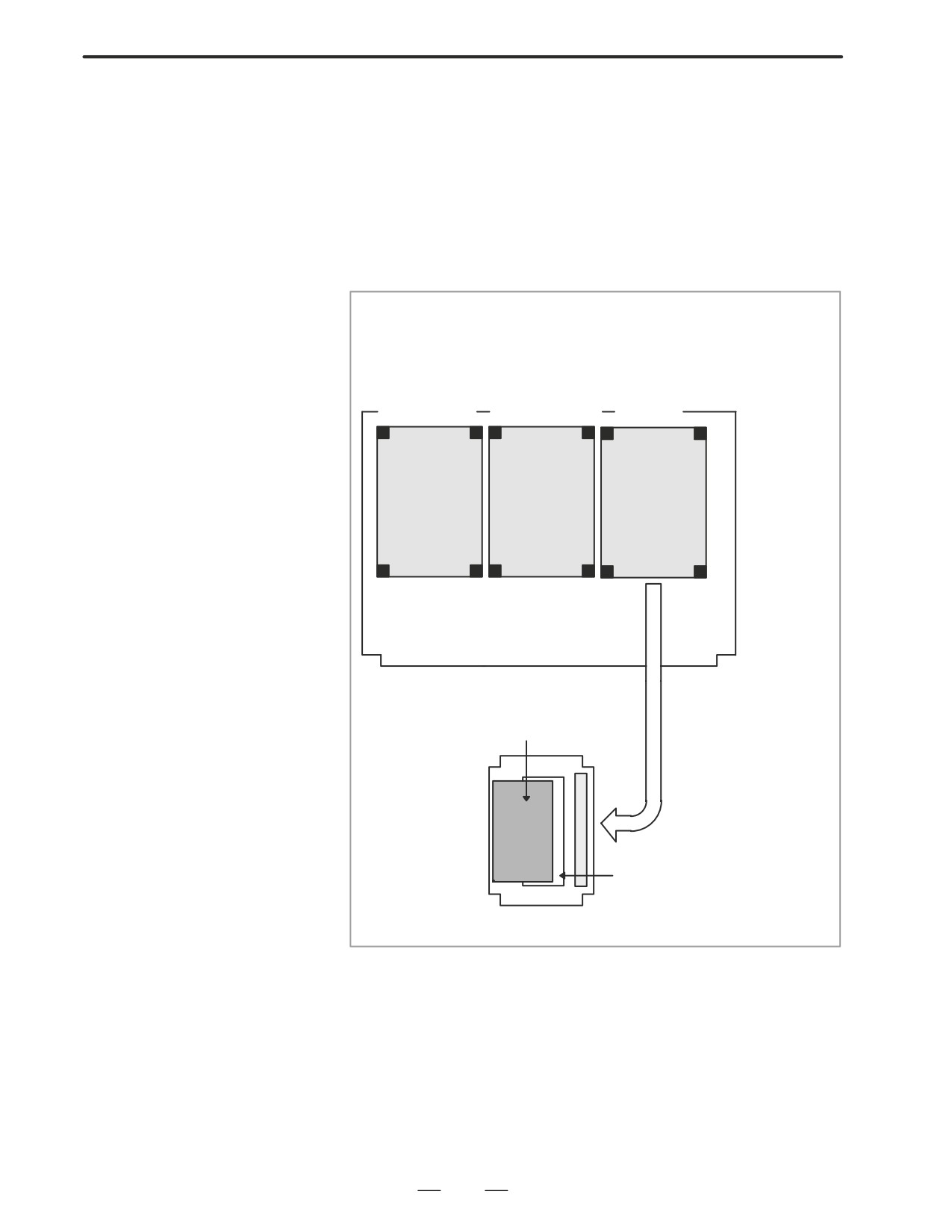
D Mounting position of the
<Motherboard>
DRAM module
The DRAM module is mounted
on the CPU card.
Remove the CPU card accord-
ing to Section 2.6.
(1)
(2)
(3)
Axis control card
Display control card
CPU card
Motherboard
DRAM module
Connector
DIMM module socket
Side B of CPU card
349