FANUC Series 16i / 18i / 160i / 180i - Model A. Maintenance Manual (B-63005EN/01) - page 10
4. INTERFACE BETWEEN NC AND PMC
B-63005EN/01
1
Nonvolatile memory control
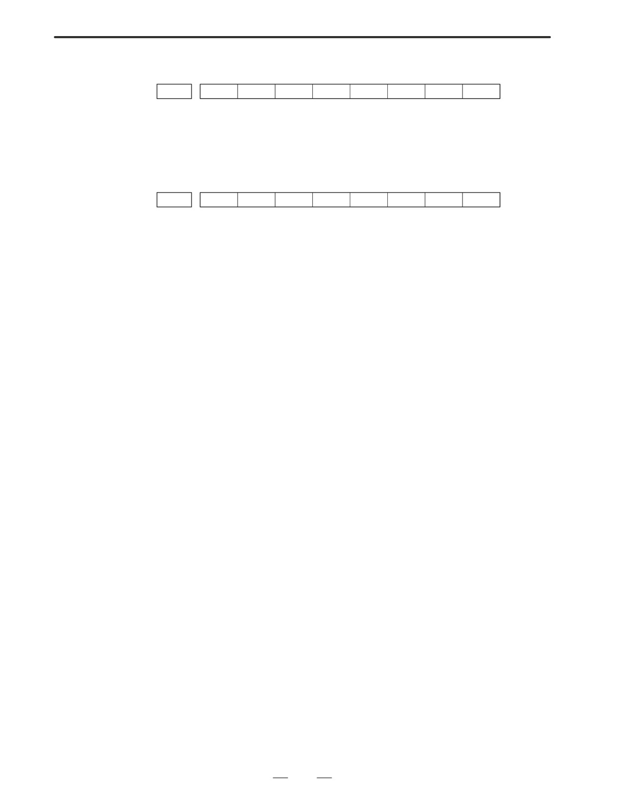
#7
#6
#5
#4
#3
#2
#1
#0
À
K016 ÀÀÀÀÀÀ
#7(MWRTF2) : For checking the writing status in nonvolatile memory
#6(MWRTF1) : Writing status in nonvolatile memory
2
PMC system parameter
The following keep relays are used by the system, therefore they
cannot be used in the sequence program.
#6
#5
#4
#3
#2
#1
#0
K017 ÀÀÀÀÀÀÀÀÀÀÀ ÀÀÀÀÀÀÀÀ
#7(DTBLDSP)
0 :
The PMC parameter data table control screen is displayed.
1 :
The PMC parameter data table control screen is not displayed.
#6(ANASTAT)
0 :
Pressing [EXEC] key initiates sampling by signal waveform display
function.
1 :
Turning power to on initiates sampling by signal waveform display
function.
#5(TRCSTAT)
0 :
Signal tracing starts by soft key [EXEC] in signal trace function.
1 :
Signal tracing starts automatically by power on in signal trace
function.
#4(MEMINP)
0 :
Data input cannot be done in memory contents display function.
1 :
Data input can be done in memory contents display function.
#2(AUTORUN)
0 :
A sequence program is executed automatically after the power is
turned on.
1 :
A sequence program is executed by sequence program soft key.
#1(PRGRAM)
0 :
Built-in programmer is not used.
1 :
Built-in programmer is used.
#0(LADMASK)
0 :
Dynamic display of ladder is executed.
1 :
Dynamic display of ladder is not executed.
260

B-63005EN/01
4.INTERFACE BETWEEN NC AND PMC
#7
#6
#5
#4
#3
#2
#1
#0
À
K018
ÀÀÀÀ
ÀÀÀÀÀÀÀÀÀÀÀÀÀÀÀ
#7(IGNDINT)
0 :
When the screen is switched to the PCMMDI screen, the CRT is initialized.
1 :
When the screen is switched to the PCMMDI screen, the CRT is not
initialized.
*It is effective for PMC-RC3/RC4
#5(CHKPRTY)
0 :
The parity check is performed for the system ROM and program
ROM/RAM.
1 :
The parity check is not performed for the system ROM and program
ROM/RAM.
#4(CALCPRTY)
0 :
The built-in programmer function performs RAM parity calculation.
1 :
The built-in programmer function does not perform RAM parity
calculation.
#3(TRNSRAM)
0 :
A ladder program is not automatically sent to the backup RAM after
on-line editing is completed.
1 :
A ladder program is automatically sent to the backup RAM after on-line
editing is completed.
#2(TRGSTAT)
0 :
The trigger stop function does not automatically start when the power is
turned on.
1 :
The trigger stop function automatically starts when the power is turned on.
#1(DBGSTAT)
0:
In the C language debug function, the automatic break processing
does not start when the power is turned on.
1 :
In the C language debug function, the automatic break processing
starts when the power is turned on.
*This flag is effective for the PMC-RC3/RC4.
#0(IGNKEY)
0 :
Function keys are enabled when a user program displays the user
screen.
1 :
Function keys are disabled when a user program displays the user
screen.
*This flag is effective for the PMC-RC3/RC4.
When this bit is set to 1 of the user screen, the screen cannot be switch to
the NC screen using function keys. A program which always sets this bit
to 0 or which changes the screen to the NC screen is required.
#7
#6
#5
#4
#3
#2
#0
À#1À
K019
ÀÀÀ
#1(C-REJECT)
0 : A C-language program is activated.
1 : A C-language program is forcibly activated.
*The flag is effective for the PMC-RC3/RC4.
These bits are status of not used for PMC management software are used
by system. Do not change the values.
Usually all the bits are 0.
261
4. INTERFACE BETWEEN NC AND PMC
B-63005EN/01
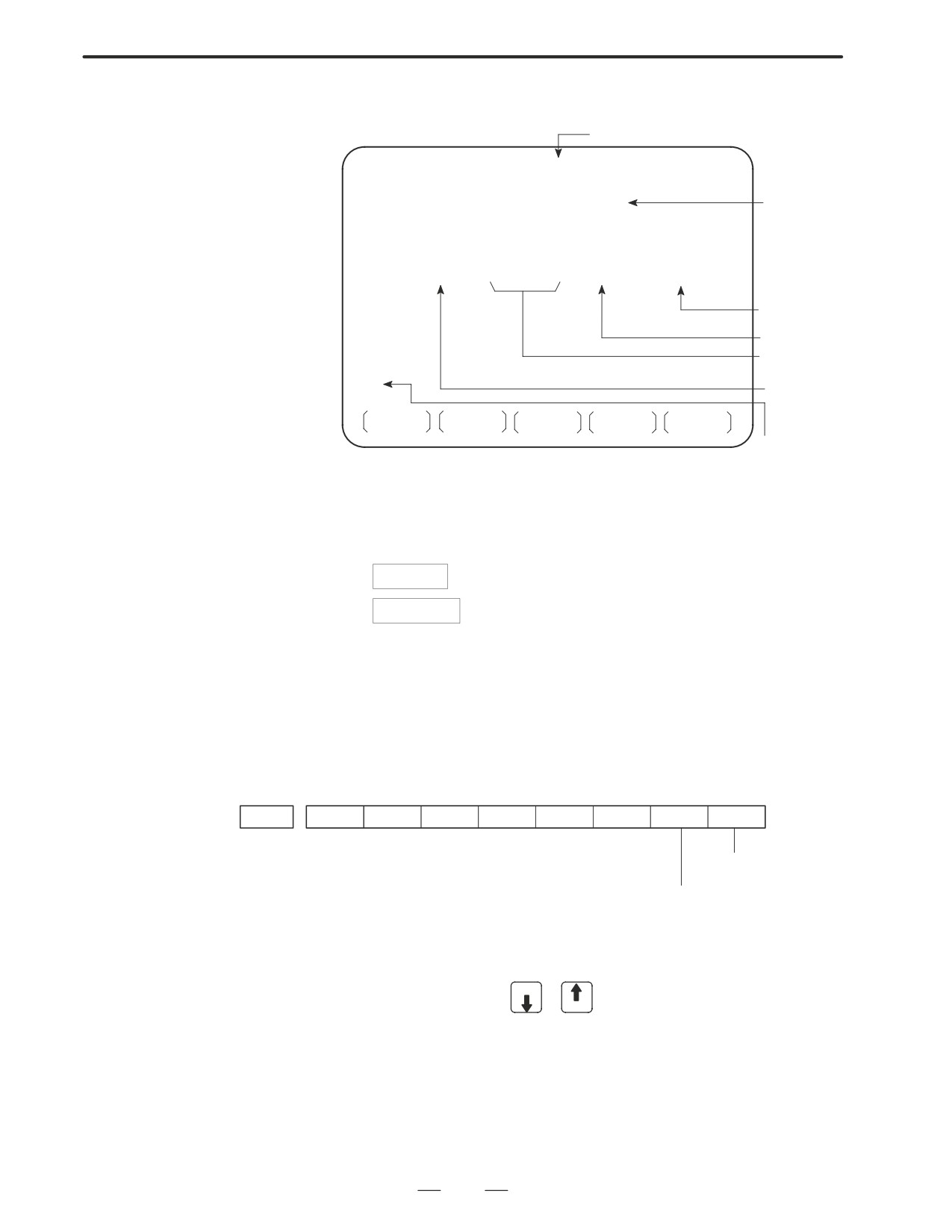
D DATA TABLE screen
1
Data table setting screen
No. of screen
PMC DATA TBL CONTROL #001
MONIT RUN
GROUP TABLE COUNT =
2
No. of
data table
groups
NO.
ADDRESS
PARAMETER TYPE NO.OF DATA
001
D0000
00000000
0
10
002
D0020
00000011
1
20
003
004
No. of
005
data table
Data length
006
Table
007
parameter
008
Data table
head ad-
dress
G.DATA
G.CONT
NO.SRH
INIT
Group no. of
data table
a. Soft key [G.DATA] : Select data display screen of data table.
(Next screen)
b.
NO. OF GROUPS
[G.CONT]: Set the no. of groups of data table.
c.
Group No.
[NO.SRH]: Move the cursor to a specified group.
d. Soft key [INIT]: Initializes the setting of data table.
No. of groups is 1, ADDRESS is D0000, PARAMETER is 0000000,
TYPE is 0, NO. OF DATA is 1860.
This operation is done usually when a sequence program is prepared.
When PMC parameters are set, internal parameters are not affected.
PARAMETER
#7
#6
#5
#4
#3
#2
À#1ÀÀ#0À
K019
ÀÀÀÀÀ
0 : Binary format
1 : BCD format
0 : Without protection for input
1 : With protection for input
TYPE
0 : 1-byte length
1 : 2-byte length
2 : 4-byte length
e. Using the page key PAGE
/
, next screen/previous screen can be
PAGE
selected.
262
B-63005EN/01
4.INTERFACE BETWEEN NC AND PMC
2
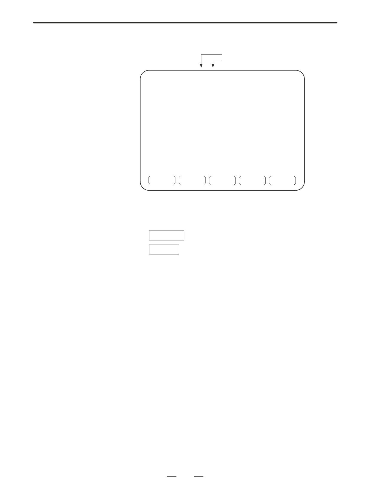
Data display screen
Group number
Page number
PMC PRM (DATA) 001/001
MONIT RUN
NO.
ADDRESS
DATA
000
D0000
0
001
D0001
0
002
D0002
0
003
D0003
0
004
D0004
0
005
D0005
0
006
D0006
0
007
D0007
0
008
D0008
0
009
D0009
0
C.DATA
G-SRCH
SEARCH
a. Soft key [C.DATA] :Returns to the data table setting screen.
(Previous screen)
b.
Group No.
[G-SRCH] : Head of the specified group is selected.
c.
Address
[SEARCH]: Searches an address in a group currently
selected.
263
4. INTERFACE BETWEEN NC AND PMC
B-63005EN/01
4.4
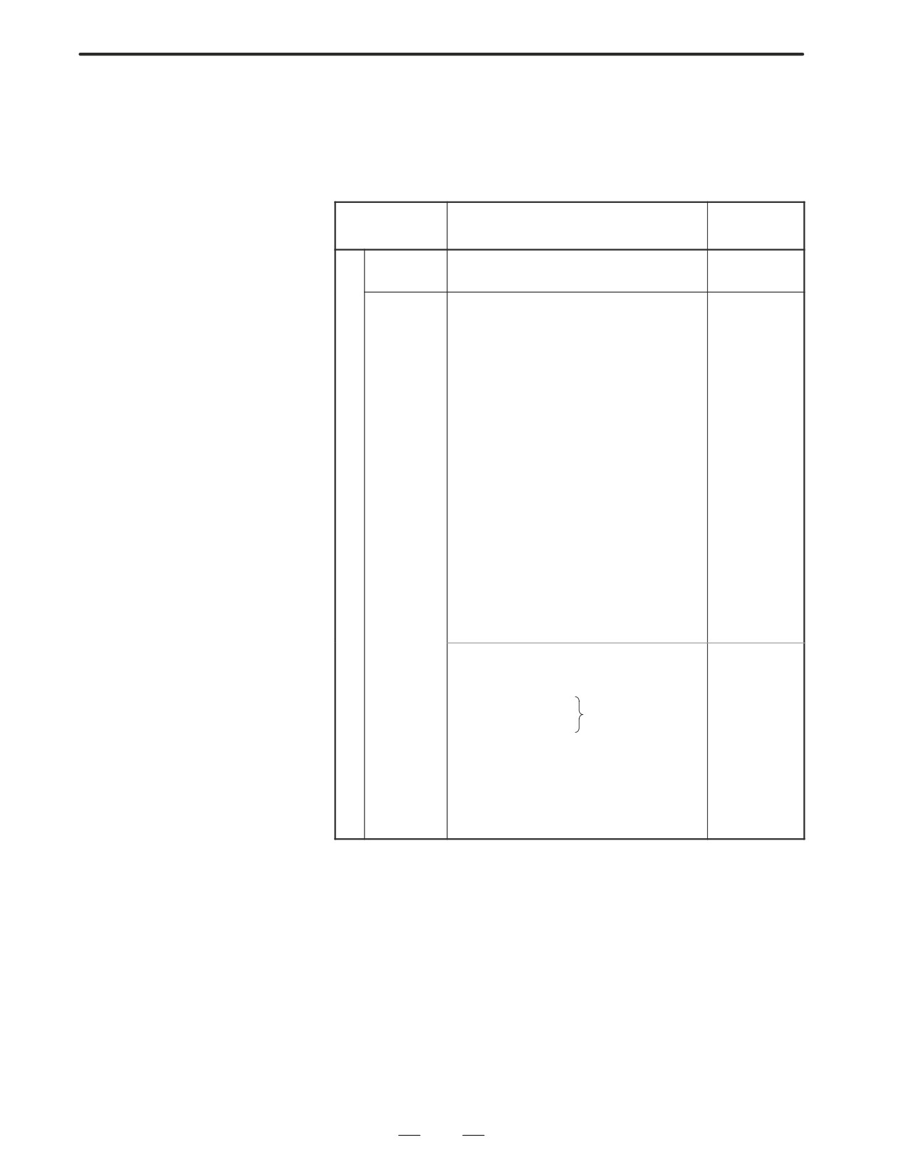
LIST OF SIGNALS BY
EACH MODE
D Automatic operation
MODE
INPUT/OUTPUT SIGNAL
FEED RATE,
ETC
EDIT
[PMC ⇒ CNC]
KEY3(Program protect key)
[PMC ⇒ CNC)
[PMC ⇒ CNC]
ST
(Cycle start)
*FV0∼7
*SP
(Feed hold)
(Feed rate over-
SBK
(Single block)
ride)
DRN
(Dry run)
*AFV0∼7
BDT1∼9
(Block delete)
(2nd feed rate
MIα
(Mirror image)
override)
STLK
(Start lock:16T/18T)
OVC
A
CDZ
(Chamfering:16T/18T)
(Override can-
U
SMZ
(In-position check:16T/18T)
cel)
T
PN1∼8
(External program no. search)
O
MINP
(External program input)
ROV1,ROV2,
M
DNCI
(DNC input mode)
HROV,
A
HSα1A∼D(Handle interrupt axis select)
*HROV0∼6
T
AFL
(Auxiliary function neglect)
(Rapid traverse
I
FIN, MFIN2, MFIN3
override)
C
(Auxiliary function complete)
SOV0∼7
MEM
MFIN, SFIN, TFIN, TFIN
(Spindle speed
O
(High speed M/S/T function com-
override)
MDI
P
plete)
E
RMT
GR1, 2
(Gear input 16T/ 18T)
R
*SSTP
(Spindle stop)
A
SAR
(Spindle speed arrival)
T
SOR
(Spindle orientation)
I
O
[CNC ⇒ PMC]
N
STL
(Cycle start LED)
SPL
(Feed hold LED)
MF, M00∼M31
MF2, M200∼M215
(Miscellaneous
function)
MF3, M300∼M315
SF, S00∼S31
(Spindle speed function)
TF, T00∼T31
(Tool function)
BF, B00∼B31
(2nd miscellaneous func.)
DEN
(Distribution end)
OP
(automatic operating)
GR1O∼GR3O(Gear selection:16M/18M)
264
B-63005EN/01
4.INTERFACE BETWEEN NC AND PMC
D Manual operation
MODE
INPUT/OUTPUT SIGNAL
FEED RATE,
ETC
Handle/
[PMC ⇒ CNC]
[PMC ⇒ CNC]
M
incremental
HSnA∼D (Axis selection) n:1∼3(No. of MPGs)
MP1, MP2
A
+α, -α
(Jog feed)
(Multiplier)
N
U
JOG
[PMC ⇒ CNC]
[PMC ⇒ CNC]
A
RT
(Rapid traverse)
*JV0∼15
L
(Manual fee-
[PMC ⇒ CNC]
drate override)
O
ZRN(Reference position return mode)
+α, -α
(Man
P
[MT ⇒ CNC]
ual feed move
E
Z
*DECα
(Reference position deceleration)
command)
R
A
R
ROV1, ROV2
T
N
[CNC ⇒ PMC]
HROV
I
ZPα
*HROV0∼6
O
ZP2α, ZP3α, ZP4α
(Rapid traverse
N
(Reference position return completion)
override)
D Others
[PMC ⇒ CNC]
MD1∼4
(Mode selection)
*ESP
(Emergency stop)
KEY1∼4
(Memory protection key)
MLK,MLKα
(All axes/ each axis machine lock)
*IT,*ITα
(All axes/ each axis machine lock)
*"MITα (interlock per axis and direction:M series)
STLK
(Start lock:T series)
*ABSM
(Manual absolute)
SVFα
(Servo off)
*FLWP
(Follow up)
ERS
(External reset)
RRW
(Reset & Rewind)
Others
EXLM
(Stored stroke limit external switching)
"LMα, RLSOT
(Software limit external setting M series)
*"Lα
(Overtravel limit)
*"EDα
(External deceleration of each axis)
[CMC ⇒ PMC]
MA
(NC ready)
SA
(Servo ready)
AL
(NC alarm)
RST
(Resetting)
BAL
(Battery alarm)
INPα
(In-position)
MVα
(Axis moving)
TAP
(Tapping)
265
5. DIGITAL SERVO
B-63005EN/01
DIGITAL SERVO
5
This chapter describes servo tuning screen required for maintenance of
digital servo and adjustment of reference position.
5.1
INITIAL SETTING SERVO PARAMETERS
267
5.2
SERVO TUNING SCREEN
277
5.3
ADJUSTING REFERENCE POSITION
(DOG METHOD)
280
5.4
DOGLESS REFERENCE POSITION SETTING
282
266
5. DIGITAL SERVO
B-63005EN/01
This section describes how to set initial servo parameters, which is used
5.1
for field adjustment of machine tool.
INITIAL SETTING
1. Turn on power at the emergency stop condition.
SERVO PARAMETERS
2. Set the parameter to display the servo tuning screen.
#7
#6
#5
#4
#3
#2
#1
#0
3111
SVS
#0 (SVS)
0 : Servo tuning screen is not displayed.
1 : Servo tuning screen is displayed.
3. Turn off the power once then turn it on again.
4. Display the servo parameter setting screen by the following
operation:
SYSTEM
key
[SV.PARA].
5. Input data required for initial setting using the cursor and page key.
SERVO SETTING
X AXIS
Y AXIS
(1)INITIAL SET BIT
00000000
00000000
PRM
2000
(2)MOTOR ID NO.
47
47
PRM
2020
(3)amr
00000000
00000000
PRM
2001
(4)cmr
2
2
PRM
1820
(5)FEED GEAR N
1
1
PRM
2084
(6)
(N/M) M
125
125
PRM
2085
(7)DIRECTION SET
111
111
PRM
2022
(8)VELOCITY PULSE NO.
8192
8192
PRM
2023
(9)POSITION PULSE NO. 12500
12500
PRM
2024
(10)REF.COUNTER
8000
8000
PRM
1821
(1) Initial set bit
#7
#6
#5
#4
#3
#2
#1
#0
2000
PRMCAL
DGPRM
PLC01
#3 (PRMCAL)
1 : Turns to 1 when the initial setting is done.
The following parameters are set automatically in
accordance with the no. of pulses of pulse coder:
PRM 2043(PK1V), PRM 2044(PK2V), PRM 2047(POA1),
PRM 2053(PPMAX),PRM 2054(PDDP),
PRM 2056(EMFCMP),
PRM 2057(PVPA), PRM 2059(EMFBAS),
PRM 2074(AALPH),PRM 2076(WKAC)
#1 (DGPRM)l
0 : Initial setting of digital servo parameter is done.
1 : Initial setting of digital servo parameter is not done.
#0 (PLC01)
0 : Values of parameter 2023 and 2024 are used as they are:
1 : Values of parameter 2023 and 2024 are multiplied by 10.
267
5. DIGITAL SERVO
B-63005EN/01
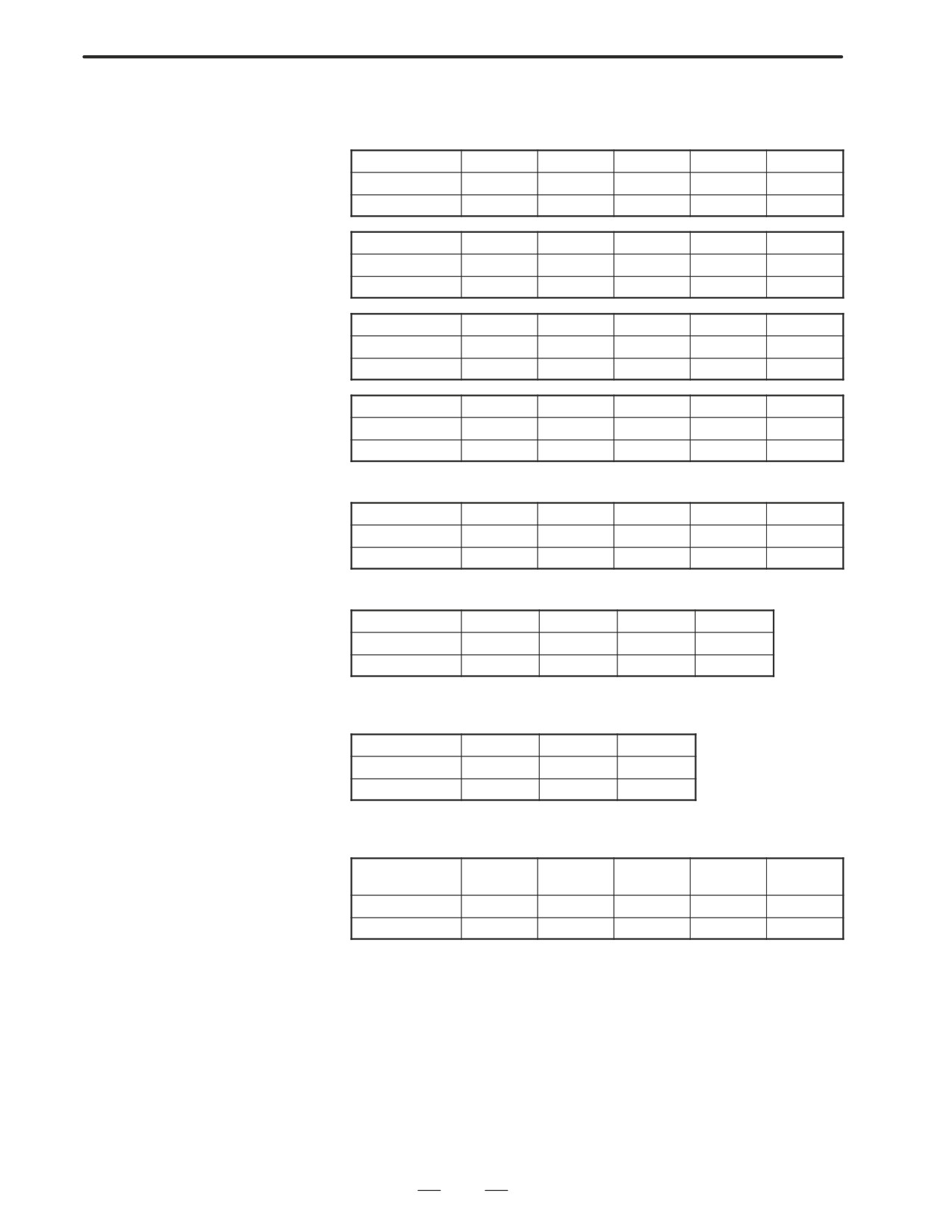
(2) Motor number
For a series servo motor
Model name
a 0.5
a 1/3000
a 2/2000
a 2.5/3000
a 3/3000
Drawing number
0113
0371
0372
0374
0123
Format number
13
61
46
84
15
Model name
a 6/2000
a 6/3000
a 12/2000
a 12/3000
a 22/1500
Drawing number
0127
0128
0142
0143
0146
Format number
16
17
18
19
27
Model name
a 22/2000
a 22/3000
a 30/1200
a 30/2000
a 30/3000
Drawing number
0147
0148
0151
0152
0153
Format number
20
21
28
22
23
Model name
a 40/FAN
a 40/2000
a 65
a 100
a 150
Drawing number
0158
0157
0331
0332
0333
Format number
29
30
39
40
41
For a L series servo motor
Model name
a L3/3000
a L6/2000
a L9/3000
a L25/3000
a L50/2000
Drawing number
0561
0562
0564
0571
0572
Format number
56 or 68
57 or 69
58 or 70
59
60
For a C series servo motor
Model name
a C3/2000
a C6/2000
a C12/2000
a C22/1500
Drawing number
0121
0126
0141
0145
Format number
7
8
9
10
For a HV series servo motor
Model name
a 12HV
a 22HV
a 30HV
Drawing number
0176
0177
0178
Format number
3
4
5
For a E and b series servo motor
Model name
a 0.5
b 1/3000
b 2/3000
b 3/3000
b 6/2000
a E1/3000
a E2/3000
a E3/3000
a E6/2000
Drawing number
0113
0101
0102
0105
0106
Format number
13
35
36
33
34
268
5. DIGITAL SERVO
B-63005EN/01
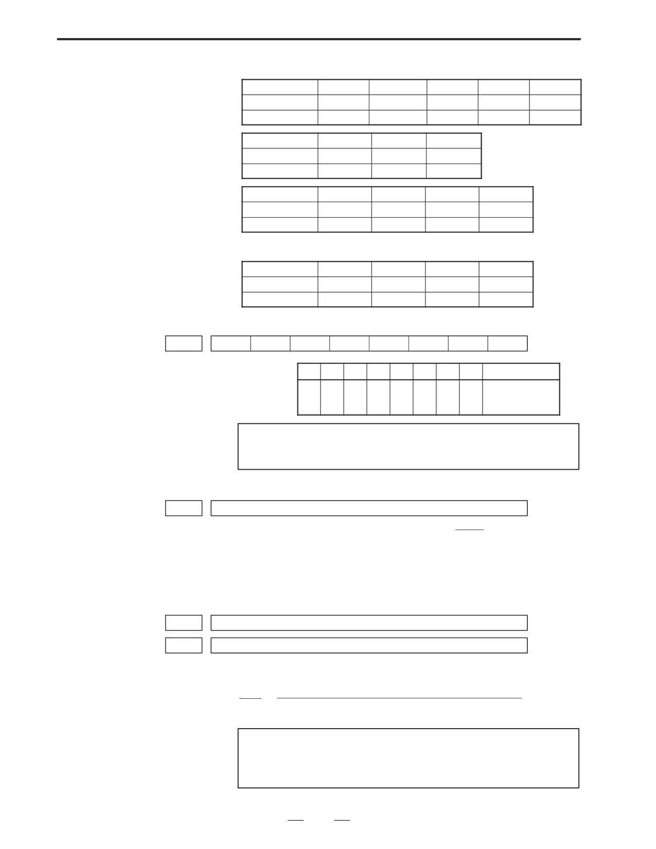
For a M series servo motor
Model name
a M2/3000
a M2.5/3000
a M3/3000
a M6/3000
a M9/3000
Drawing number
0376
0377
0161
0162
0163
Format number
97
98
24
25
26
Model name
a M22/3000
a M30/3000
a M50/3000
Drawing number
0165
0166
0169
Format number
100
101
108
Model name
a M6HV
a M9HV
a M22HV
a M30HV
Drawing number
0182
0183
0185
0186
Format number
104
105
106
107
For linear motor
Model name
1500A
3000B
6000B
9000B
Drawing number
0410
0411
0412
0413
Format number
90
91
92
93
(3) Arbitrary AMR function (for 5-0S to 3-0S)
#7
#6
#5
#4
#3
#2
#1
#0
PRM
2001
AMR7
AMR6
AMR5
AMR4
AMR4
AMR3
AMR2
AMR1
For each axis
#7
#6
#5
#4
#3
#2
#1
#0
Motor model
1
0
0
0
0
0
1
0
5-0S
0
0
0
0
0
0
1
1
4-0S, 3-0S
0
0
0
0
0
0
0
0
other than above
NOTE
Set ”00000000” for serial pulse coder C.
(4) CMR
PRM
1820
Command multiply ratio
1
1) When CMR is 1/2 to 1/27
Set value=
+100
CMR
2) When CMR is 0.5 to 48
Set value=2×CMR
(5) Turn off the power then back on.
(6) Feed gear N/M
PRM
2084
n for flexible feed gear
PRM
2085
m for flexible feed gear
1) For serial pulse coder A or B, and serial a pulse coder.
Number of feedback pulses per revolution of motor
n
=
m
1000000
NOTE
For serial pulse coder B, use a value not exceeding 250,000
as the number of feedback pulses per revolution.
269
5. DIGITAL SERVO
B-63005EN/01
<<Examples of calculation>>
1/1000 mm
1/10000 mm
One revolution 8mm
n=1/m=125
n=2/m=25
of motor
10mm
n=1/m=100
n=1/m=10
12mm
n=3/m=250
n=3/m=25
(7) Direction of travel
PRM
2022
Rotational direction of motor
111 : Normal (clockwise)
-111 : Reverse (counterclockwise)
(8) Number of velocity pulses and position pulses
1) For serial pulse coder A or B, or serial a pulse coder
Increment system : 1/1000mm
Increment system : 1/10000mm
Paramter No
Closed loop
Semi-closed loop
Closed loop
Semi-closed loop
High resolution setting
2000
xxxx xxx 0
xxxx xxx 1
Separate detector
1815
0010 0010
0010 0000
0010 0010
0010 0000
No. of velocity feedback pulses
2023
8192
819
No. of position feedback pulses
2024
NS
12500
NS/10
1250
NOTE
1
NS is the number of position feedback pulses per one
revolution of the motor (multiplied by four)
2
The 5-0S to 3-0S motors have different numbers of poles.
Set parameter 2001.
3
Even if the system employs a closed loop, bit 3 of parameter
2002 is 1 and bit 4 is 0.
(9) Reference counter
PRM
1821
Reference counter capacity for each axis (0 - 99999999)
6. Turn off the power then back on.
(10) FSSB display and setting screen
Connecting the CNC control unit to servo amplifiers via a
high-speed serial bus (FANUC Serial Servo Bus, or FSSB), which
uses only one fiber optics cable, can significantly reduce the amount
of cabling in machine tool electrical sections.
Axis settings are calculated automatically according to the
interrelationships between axes and amplifiers entered on the FSSB
setting screen. Parameter Nos. 1023, 1905, 1910 to 1919, 1936, and
1937 are specified automatically according to the results of the
calculation.
D Display
The FSSB setting screen displays FSSB-based amplifier and axis
information. This information can also be specified by the operator.
1. Press function key
SYSTEM
2. To display [FSSB], press continuous menu key
several times.
3. Pressing soft key
[FSSB] causes the AMP SET screen (or the
previously selected FSSB setting screen) to appear, with the following
soft keys displayed.
270
5. DIGITAL SERVO
B-63005EN/01
AMP
AXIS
MAINTE
(OPRT)
The FSSB setting screens include: AMP SET, AXIS SET, and AMP
MAINTENANCE.
Pressing soft key [AMP] causes the AMP SET screen to appear.
Pressing soft key [AXIS] causes the AXIS SET screen to appear.
Pressing soft key [MAINTE] causes the AMP MAINTENANCE
screen to appear.
1)
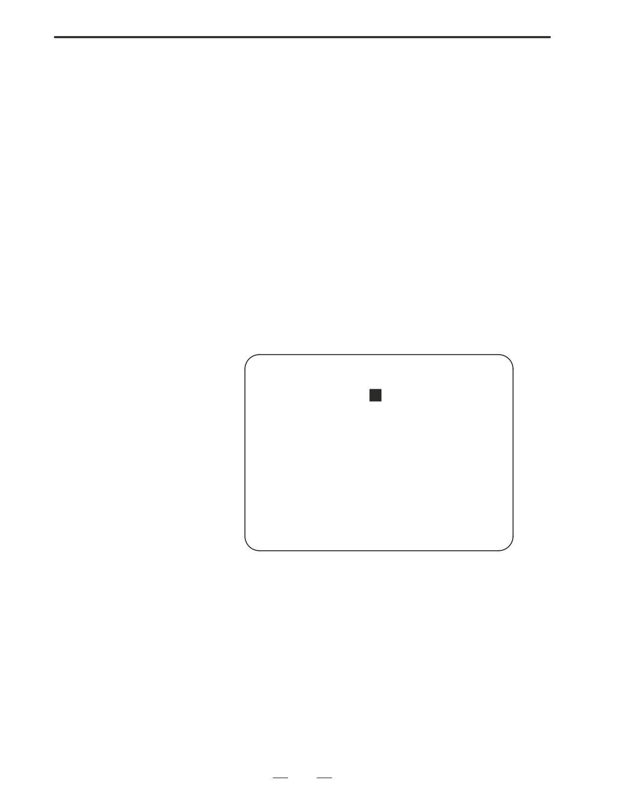
Amplifier setting screen
The amplifier setting screen consists of two sections: the first section
displays information about the slave, while the second section
displays information about the pulse modules.
AMPLIFIER SETTING
O1000 N00001
NO. AMP
SERIES UNIT
CUR. AXIS NAME
1
A1-L
α SVM-HV
40AL
1
X
2
A1-M
α
SVM
12A
2
Y
3
A2-L
β
SVM
40A
3
Z
4
A3-L
α
SVM
20A
4
A
5
A3-M
α
SVM
40A
5
B
7
A4-L
α
SVU
240A
6
C
NO. EXTRA
TYPE PCB ID
6
M1
A
0000 DETECTOR(8AXES)
8
M2
B
12AB
>_
MDI **** *** ***
13:11:56
[ AMP
][ AXIS
][ MAINTE ][
][(OPRT)]
The amplifier setting screen consists of the following items:
D NO. (slave number)
The numbers of up to ten slaves (up to eight amplifiers and up to two
pulse modules) connected via the FSSB are displayed sequentially,
with the one nearest to the CNC being number 1.
D AMP (amplifier type)
The amplifier type display consists of the letter A, which stands for
”amplifier,” a number that indicates the placing of the amplifier, as
counted from that nearest to the CNC, and a letter such as L (first axis)
or M (second axis) indicating the placing of the axis in the amplifier.
D AXIS NO. (controlled axis number)
The axis number of each controlled axis specified in parameters (Nos.
1920 to 1929) is displayed. If a number specified in these parameters
falls outside the range of between 1 and the maximum number of
controlled axes, 0 is displayed.
D NAME (controlled axis name)
The axis name assigned to a parameter (No. 1020) corresponding to
a particular controlled axis number is displayed. If the controlled axis
number is 0, - is displayed.
271
5. DIGITAL SERVO
B-63005EN/01
D
The following items are displayed as amplifier information:
⋅ UNIT (servo amplifier unit type)
⋅ SERIES (servo amplifier series)
⋅ CURRENT (maximum rating)
D
The following items are displayed as pulse module information:
⋅ SEPARATE
This display consists of the letter M, which stands for ”pulse
module” and a number indicating the placing of the pulse module,
as counted from that nearest to the CNC.
⋅ TYPE
This display is a letter indicating the type of the pulse module.
⋅ PCB ID
This display consists of four digits indicating the pulse module ID
(hexadecimal). The pulse module ID is followed by DETECTOR
(8 AXES) for the eight-axis separate detector module or
DETECTOR (4 AXES) for the four-axis separate detector module.
2)
Axis setting screen
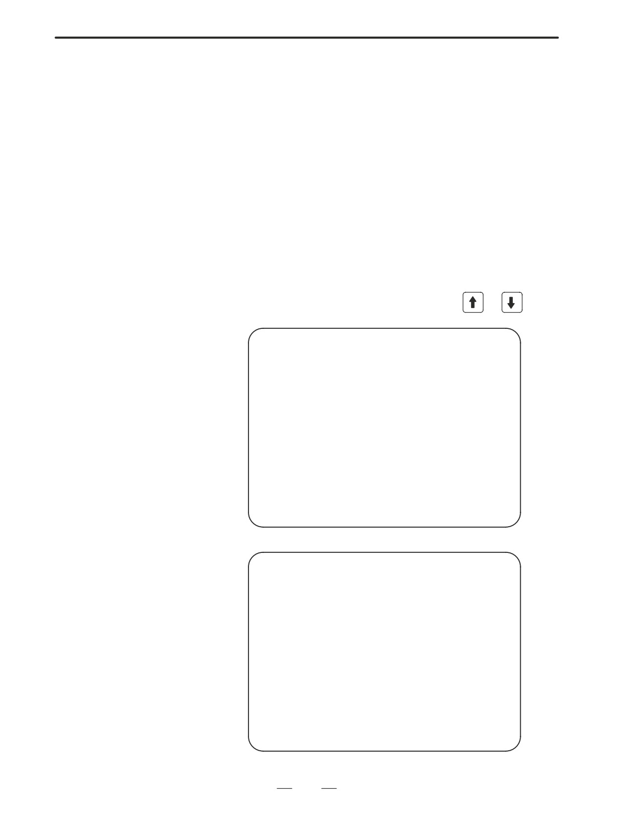
The axis setting screen displays the information shown below:
AXIS SETTING
O1000 N00001
AXIS NAME AMP
M1 M2
1-DSF Cs
TNDM
1
X A1-L
0
0
0
0
1
2
Y A1-M
1
0
1
0
0
3
Z A2-L
0
0
0
1
0
4
A A3-L
0
0
0
0
2
5
B A3-M
0
0
0
0
0
6
C A4-L
0
0
0
0
0
>_
MDI **** *** ***
13:11:56
[ AMP
][ AXIS
][ MAINTE ][
][(OPRT)]
This axis setting screen displays the following items:
D AXIS NO. (controlled axis number)
This item is the placing of the NC controlled axis.
D NAME (controlled axis name)
D AMP (type of the amplifier connected to each axis)
D M1 (connector number for pulse module 1)
This item is the number of the connector for pulse module 1, specified
in parameter No. 1931.
D M2 (connector number for pulse module 2)
This item is the number of the connector for pulse module 2, specified
in parameter No. 1932.
272
5. DIGITAL SERVO
B-63005EN/01
D TWO AXES
This item is the value specified in bit 0 (parameter 1 DSP) of parameter
No. 1904. It is 1 for an axis (such as a learning control axis, high-speed
current loop axis, or high-speed interface axis) that exclusively uses
a DSP, which is usually shared by two axes.
D Cs: Cs contour controlled axis
This item is the value specified in parameter No. 1933. It is 1 for the
Cs contour controlled axis.
D TANDEM (M series only)
This item is the number specified in parameter No. 1934. Consecutive
odd and even numbers are displayed for the master and slave axes for
tandem control.
3) Amplifier maintenance screen
The amplifier maintenance screen displays maintenance information
for servo amplifiers. This screen consists of the following two pages,
either of which can be selected by pressing the
or
key.
AMPLIFIER MAINTENANCE
O1000 N00001
AXIS NAME AMP
SERIES
UNIT AXES CUR.
1
X A1-L
α SVM-HV
2
40AL
2
Y A1-M
α
SVM
2
12A
3
Z A2-L
β
SVM
1
40A
4
A A3-L
α
SVM
2
20A
5
B A3-M
α
SVM
2
40A
6
C A4-L
α
SVU
1
240A
MDI **** *** ***
13:11:56
[ AMP
][ AXIS
][ MAINTE ][
][
]
AMPLIFIER MAINTENANCE
O1000 N00001
AXIS
NAME EDITION
TEST
MAINTE-NO.
1
X
01A
970123
01
2
Y
01A
970123
01
3
Z
01A
970123
01
4
A
02B
970123
01
5
B
02B
970123
01
6
C
02B
970123
01
MDI **** *** ***
13:11:56
[ AMP
][ AXIS
][ MAINTE ][
][
]
273
5. DIGITAL SERVO
B-63005EN/01
The amplifier maintenance screen displays the following items:
D AXIS NO. (controlled axis number)
D NAME (controlled axis name)
D AMP (type of amplifier connected to each axis)
D SERIES (servo amplifier series of an amplifier connected to each axis)
D UNIT (unit type of a servo amplifier connected to each axis)
D NO. OF AXES (maximum number of axes controlled by an amplifier
connected to each axis)
D CURRENT (maximum rating for amplifiers connected to each axis)
D VERSION (unit version number of an amplifier connected to each
axis)
D TEST DATE (date of test performed on an amplifier connected to each
axis)
Example) 970123 = January 23, 1997
D MAINTENANCE NO. (engineering change number for an amplifier
connected to each axis)
D Setting
On an FSSB setting screen (other than the amplifier maintenance screen),
pressing soft key [(OPRT)] displays the following soft keys:
SET
READ
INPUT
To enter data, place the machine in MDI mode or the emergency stop state,
position the cursor to the point where a desired item is to be input, then
enter the desired data and press soft key [INPUT] (or the
INPUT
key on the
MDI panel).
When soft key [SET] is pressed after data has been entered, a warning
message is displayed if the entered data contains an error. When the data
is satisfactory, the corresponding parameter is set up.
To restore the previous value of a parameter if, for example, an entered
value is incorrect, press soft key [READ].
When the power is turned on, values are read from the parameters and
displayed on the screen.
CAUTION
1
For the parameters to be specified on the FSSB setting
screen, do not attempt to enter values on the parameter
screen using the MDI or a G10 command. Use only the
FSSB screen to enter values for these parameters.
2
If pressing soft key [SET] results in a warning message
being displayed, retry data entry, or press soft key [READ]
to clear the warning message. Note that pressing the reset
key does not clear the warning message.
274
5. DIGITAL SERVO
B-63005EN/01
1) Amplifier setting screen
AMPLIFIER SETTING
O1000 N00001
NO. AMP
SERIES UNIT
CUR. AXIS NAME
1
A1-L
α SVM-HV
40AL
1
X
2
A1-M
α
SVM
12A
2
Y
3
A2-L
β
SVM
40A
3
Z
4
A3-L
α
SVM
20A
4
A
5
A3-M
α
SVM
40A
5
B
7
A4-L
α
SVU
240A
6
C
NO. EXTRA
TYPE PCB ID
6
M1
A
0000 DETECTOR(8AXES)
8
M2
B
12AB
>_
MDI **** *** ***
13:11:56
[SETTING][
][ READ ][
][ INPUT ]
The amplifier setting screen displays the following items:
D AXIS NO. (controlled axis number)
For this item, enter a value of between 1 and the maximum number of
controlled axes. If a number that falls outside this range is entered, the
warning message ”INVALID FORMAT” appears. If the entered
controlled axis number is duplicate or
0, the warning message
”SPECIFIED DATA IS OUT OF RANGE” appears when soft key
[SET] is pressed to assert the entered value. In this case, no value can
be entered for the parameter.
2) Axis setting screen
AXIS SETTING
O1000 N00001
AXIS NAME AMP
M1 M2
1-DSF Cs
TNDM
1
X A1-L
0
0
0
0
1
2
Y A1-M
1
0
1
0
0
3
Z A2-L
0
0
0
1
0
4
A A3-L
0
0
0
0
2
5
B A3-M
0
0
0
0
0
6
C A4-L
0
0
0
0
0
>_
MDI **** *** ***
13:11:56
[SETTING][
][ READ ][
][ INPUT ]
On the axis setting screen, the following items can be specified:
D M1 (connector number for pulse module 1)
For an axis that uses pulse module 1, enter a connector number using
a number in the range of between 1 and the maximum number of axes
for pulse module 1. When pulse module 1 need not be used, enter 0.
If a number that falls outside the valid range is entered, the warning
message ”INVALID FORMAT” is displayed.
275
5. DIGITAL SERVO
B-63005EN/01
D
M2 (connector number for pulse module 2)
For an axis that uses pulse module 2, enter a connector number using
a number in the range of between 1 and the maximum number of axes
for pulse module 2. When pulse module 2 need not be used, enter 0.
If a number that falls outside the valid range is entered, the warning
message ”INVALID FORMAT” is displayed.
D
TWO AXES
Enter 1 for the following axes, each of which exclusively uses a DSP,
which is usually shared by two axes. If a number other than 0 or 1 is
entered, the warning message ”INVALID FORMAT” is displayed.
⋅ Learning control axis
⋅ High-speed current loop axis
⋅ High-speed interface axis
D
Cs (Cs contour controlled axis)
Enter 1 for the Cs contour controlled axis. If a number other than 0
or 1 is entered, the warning message ”INVALID FORMAT” is
displayed.
D
TANDEM
Enter odd and even numbers for the master and slave axes for tandem
control. These numbers must be consecutive and in the range of
between 1 and 8. If a number that falls outside the valid range is
entered, the warning message ”INVALID FORMAT” is displayed.
When soft key [SET] is pressed on the axis setting screen after data entry,
the warning message ”SPECIFIED DATA IS OUT OF RANGE” is
displayed if any of the following conditions is satisfied.
D Both M1 and M2 are nonzero for an axis.
D Any two of TWO AXES, Cs, and TANDEM are nonzero for an axis.
D A duplicate value is specified for M1.
D A duplicate value is specified for M2.
D A duplicate value is specified for Cs.
D A duplicate value is specified for TANDEM.
D An invalid master/slave axis pair is specified for TANDEM.
276
5. DIGITAL SERVO
B-63005EN/01
5.2
SERVO TUNING
SCREEN
5.2.1
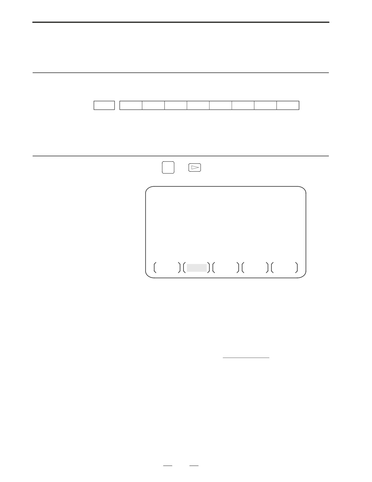
Set a parameter to display the servo tuning screen.
Parameter Setting
#7
#6
#5
#4
#3
#2
#1
#0
3111
SVS
#0 (SVS)
0 : Servo tuning screen is not displayed.
1 : Servo tuning screen is displayed.
5.2.2
SYSTEM
1. Press
key
and soft key [SV. PARA] in this order.
Displaying Servo
2. Press soft key [SV.TUN] to select the servo tuning screen.
Tuning Screen
SERVO TUNING
01234 N12345
(PAMAMETER)
(MONITOR)
(1)
FUN.BIT
00000000
ALARM 1
00000000
(9)
(2)
LOOP GAIN
3000
ALARM 2
00000000
(10)
(3)
TURNING SET.
0
ALARM 3
10000000
(11)
(4)
SET PERIOD
50
ALARM 4
00000000
(12)
(5)
INT.GAIN
113
ALARM 5
00000000
(13)
(6)
PROP.GAIN
-1015
LOOP GAIN
2999
(14)
(7)
FILER
0
POS ERROR
556
(15)
(8)
VELOC.GAIN
125
CURRENT%
10
(16)
SPEED RPM
100
(17)
SV SET
SV TUN
OPE
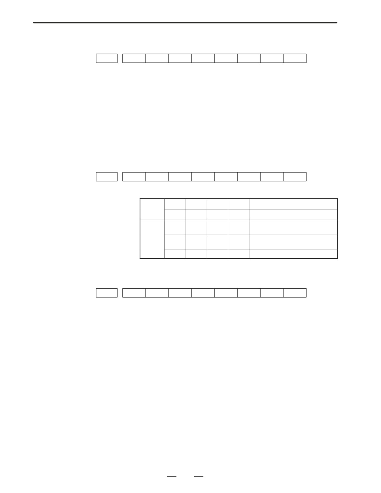
(1) Function bit : PRM 2003
(2) Loop gain : PRM 1825
(3) Tuning start : (Used by automatic servo tuning function)
(4) Set period : (Used by automatic servo tuning function)
(5) Integral gain
: PRM 2043
(6) Proportional gain : PRM 2044
(7) Filter
: PRM 2067
(PRM 2021)+256
(8) Velocity gain
Set value=
×100
256
(9) Alarm 1 : DGN 200 (Details of alarm 400 and 414)
(10) Alarm 2 : DGN 201 (Details of disconnection alarm, overload)
(11) Alarm 3 : DGN 202 (Details of alarm 319)
(12) Alarm 4 : DGN 203 (Details of alarm 319)
(13) Alarm 5 : DGN 204 (Details of alarm 414)
(14) Loop gain : Actual loop gain
(15) Position error : Actual position error(DGN 300)
(16) Current(%) : Indicate current with % to the rated value.
(17) Speed RPM : Number of motor actual rotation
277
5. DIGITAL SERVO
B-63005EN/01
#7
#6
#5
#4
#3
#2
#1
#0
Alarm1
OVL
LV
OVC
HCA
HVA
DCA
FBA
OFA
DGN (200)
:
#7 (OVL)
:
Overload alarm
#6 (LV)
:
Insufficient voltage alarm
#5 (OVC)
:
Overcurrent alarm
#4 (HCA)
:
Abnormal current alarm
#3 (HVA)
:
Excessive voltage alarm
#2 (DCA)
:
Discharge alarm
#1 (FBA)
:
Disconnection alarm
#0 (OFA)
:
Overflow alarm
#7
#6
#5
#4
#3
#2
#1
#0
Alarm2
ALD
EXP
DGN (201) ⇓
Over-
0
—
—
—
Amplifier overheat
load
alarm
1
—
—
—
Motor overheat
Discon-
1
—
—
0
Built-in pulse coder disconnection
nection
(Hardware)
alarm
1
—
—
1
Separate type pulse coder disconnec-
tion (Hardware)
0
—
—
0
Pulse coder disconnection (software)
#7
#6
#5
#4
#3
#2
#1
#0
Alarm3
CSA
BLA
PHA
RCA
BZA
CKA
SPH
DGN (202)
:
#6 (CSA)
:
Hardware of serial pulse coder is abnormal.
#5 (BLA)
:
Battery voltage is in low (warning).
#4 (PHA)
:
Serial pulse coder or feedback cable is abnormal.
Counting the feedback signal is in error.
#3 (RCA)
:
Serial pulse coder is faulty.
Counting is in error.
If the RCA bit is set to 1 when both the FBA bit (bit 1 of alarm 1) and
ALD bit of alarm 2 are set to 1 and the EXP bit of alarm 2 (internal
hardware disconnection) is set to 1, a count miss alarm (CMAL)
occurs in the α pulse coder.
#2 (BZA)
:
Battery voltage becomes 0.
Replace batteries and set the reference position.
#1 (CKA)
:
Serial pulse coder is faulty.
Internal block has stopped.
#0 (SPH)
:
Serial pulse coder or feedback cable is faulty.
Counting the feedback signal is in error.
278
5. DIGITAL SERVO
B-63005EN/01
#7
#6
#5
#4
#3
#2
#1
#0
Alarm4
DTE
CRC
STB
DGN (203)
:
#7 (DTE)
:
Communication error of serial pulse coder.
There is no response.
#6 (CRC)
:
Communication error of serial pulse coder.
Transmitted data is in error.
#5 (STB)
:
Communication error of serial pulse coder.
Transmitted data is in error.
#7
#6
#5
#4
#3
#2
#1
#0
Alarm3
OFS
MCC
LDM
PMS
DGN (204)
:
#6 (OFS)
:
A/D conversion of current value of digital servo is abnormal.
#5 (MCC)
:
Contacts of electro-magnetic contactor of servo amplifier is blown
#4 (LDM)
:
LED of serial pulse coder is abnormal.
#3 (PMS)
:
No. of feedback pulses are in error because serial pulse coder C or
feedback cable is faulty.
279
5. DIGITAL SERVO
B-63005EN/01
5.3
ADJUSTING
REFERENCE
POSITION
(DOG METHOD)
5.3.1
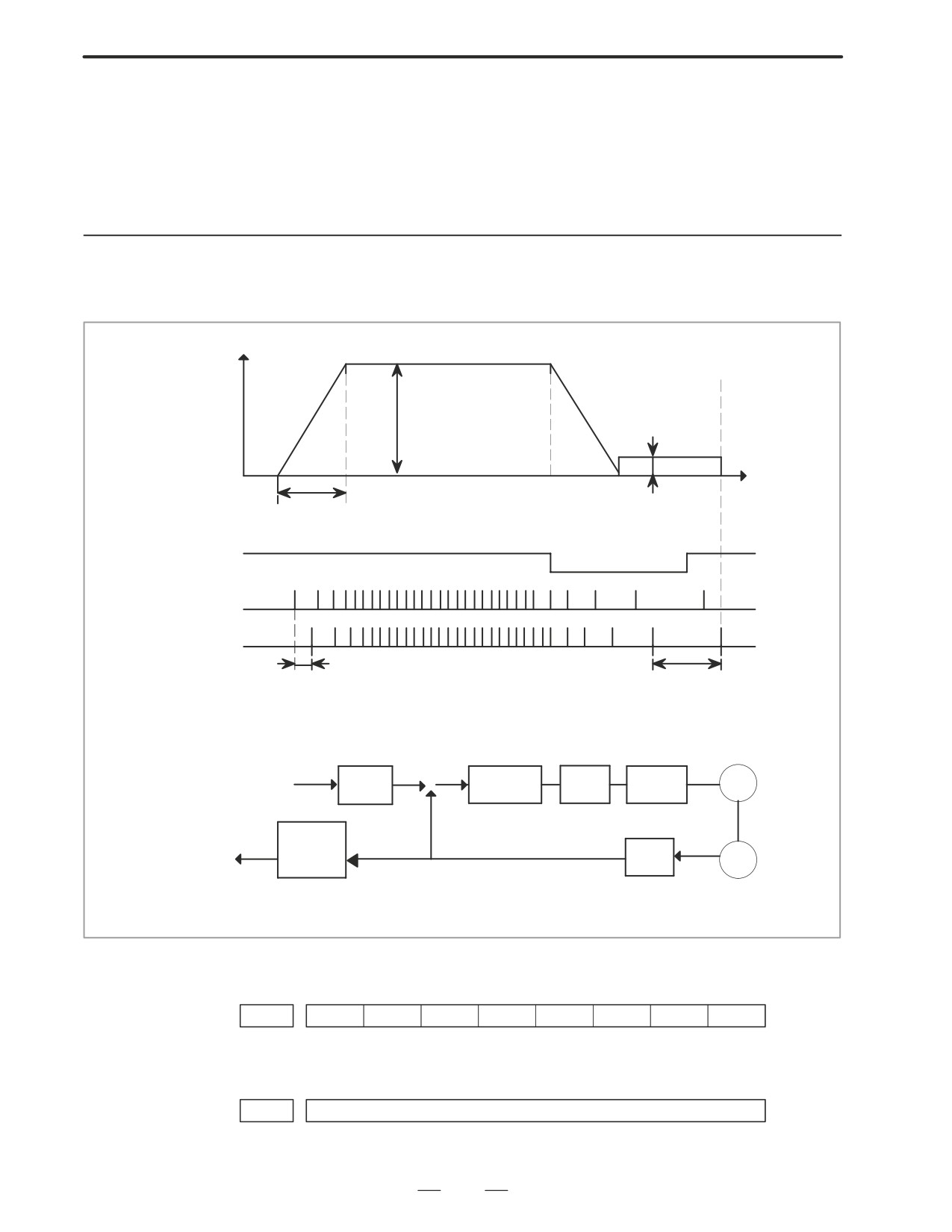
General
Speed
Rapid traverse
(PRM1420α)
FL rate
(PRM1425 α )
Time
Rapid traverse acc./dec. time constant (PRM1620 α )
*DECα
PCZ
Grid
Grid shift amount
Reference counter capacity
(PRM1850)
(PRM1821)
10mm/rev
10000P
+
Error
Proportion
Speed
CMR
f
gain
M
Command
counter
loop
–
(Serial)
4
Refere
GRID
FFG
PC
count.
10000P/rev
Counter capacity
(Flexible feed gear)
10000P
D Parameter
#7
#6
#5
#4
#3
#2
#1
#0
PRM
1002
DLZ
#1(DLZ)l
0 : Reference position return method is normal (dog).
1 : Dogless reference position setting is used.
PRM
1821
Reference counter capacity
[P]
No. of feedback pulses or its division by an integer is set.
280
5. DIGITAL SERVO
B-63005EN/01
PRM
1850
Grid shift amount per axis
[P]
When the resolution is 0.0001mm, set the value in the unit ten times
the detection unit.
#7
#6
#5
#4
#3
#2
#1
#0
PRM
1815
APC
APZ
OPT
#5(APC)
0 : Position detector is other than absolute pulse coder.
1 : Position detector is absolute pulse coder.
#4(APZ)
Zero position of absolute pulse coder is :
0 : Not established
1 : Established
(Turns to 1 after establishment)
To manually change the value of the APZ bit from 0 to 1 without first
returning to the reference position
when using serial pulse coder α , follow this procedure: Back up the
data with the battery and give the motor one or more turns.
Turn the power off then on again, then change the APZ bit setting
from 0 to 1.
#1(OPT)
0 : Position detection is performed by the pulse coder built in the motor.
1 : Separate type pulse coder or linear scale is used.
D Separate Type Pulse
Coder or Linear Scale is
Used
PRM
1821
Reference counter capacity per axis
[P]
Normally, the number of feedback pulses per motor revolution is set to
the reference counter capacity.
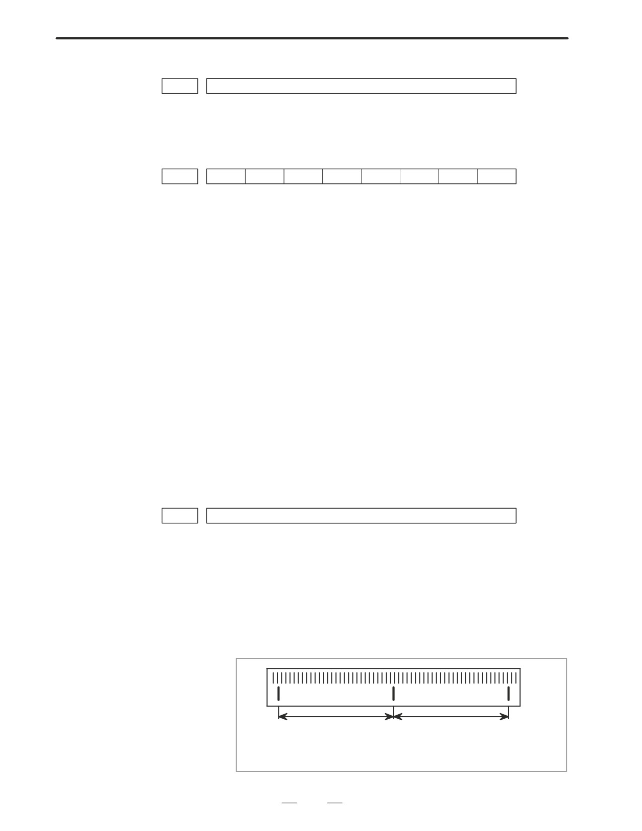
When plural reference marks are on a linear scale, a quotient of the
distance between the reference marks divided by an interfer may be used
as a reference counter capacity:
Example)
(1µ m)
300mm ⇒ reference counter
30000
20000
15000
10000 etc
281
5. DIGITAL SERVO
B-63005EN/01
When there are no dog nor limit switch for reference position return, this
5.4
function enables the tool to return the reference position that is set by
DOGLESS
MTB.
REFERENCE
When the absolute position detector is used, the reference position once
POSITION SETTING
set remains also during power off. When the absolute detector is replaced
or absolute position is lost, perform this setting.
5.4.1
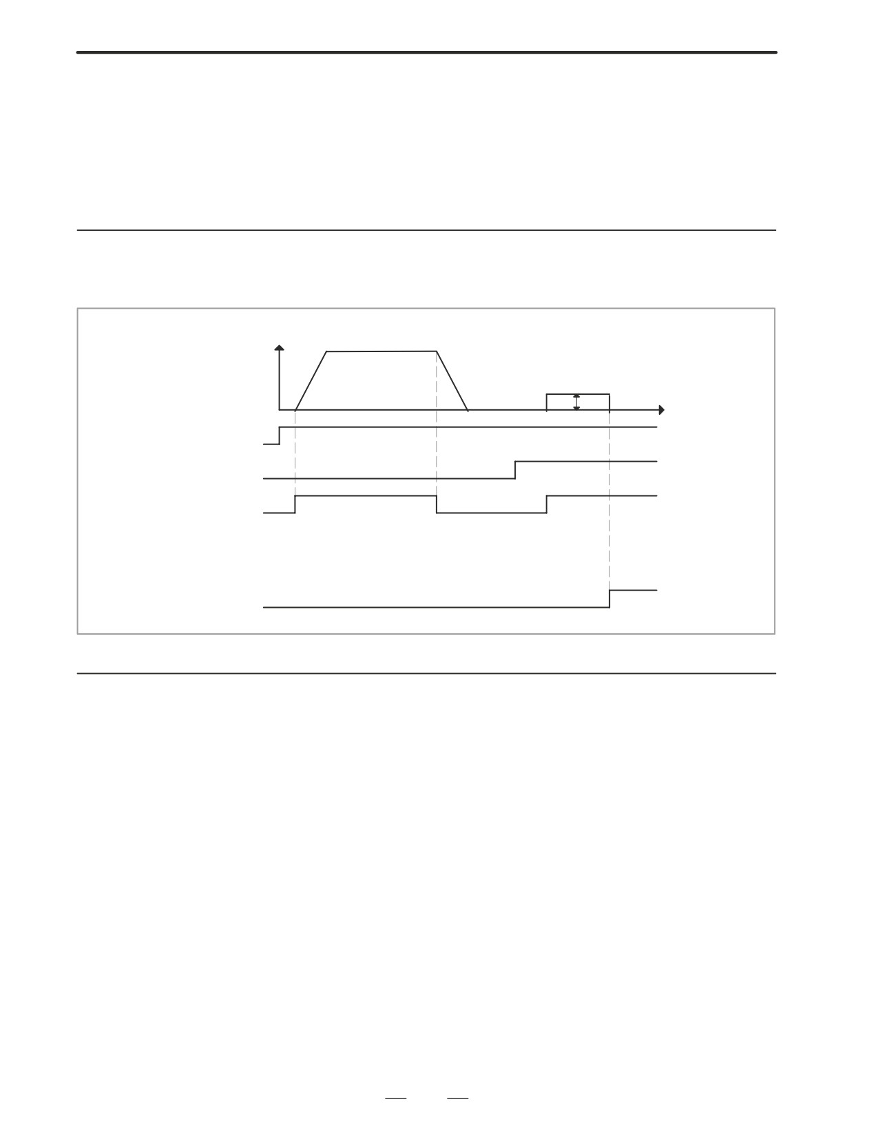
General
Speed
Reference position return
FL rate (PRM 1425)
Time
JOG
ZRN
+Jα
GRID
ZP α
5.4.2
Operation
1
Move the tool near the reference position using a manual operation.
2
Select the reference position return mode or switch.
3
Press a button for an axis-and-direction-select-signal + or -, and the
machine moves to the next grid, then stops.
(This position is set as the reference position).
After the reference position has been set, select the reference position
return mode(SRN signal is 1) and turn on an axis-and-direction-
select signal, then the tool returns to the reference position.
282
5. DIGITAL SERVO
B-63005EN/01
5.4.3
Associated Parameters
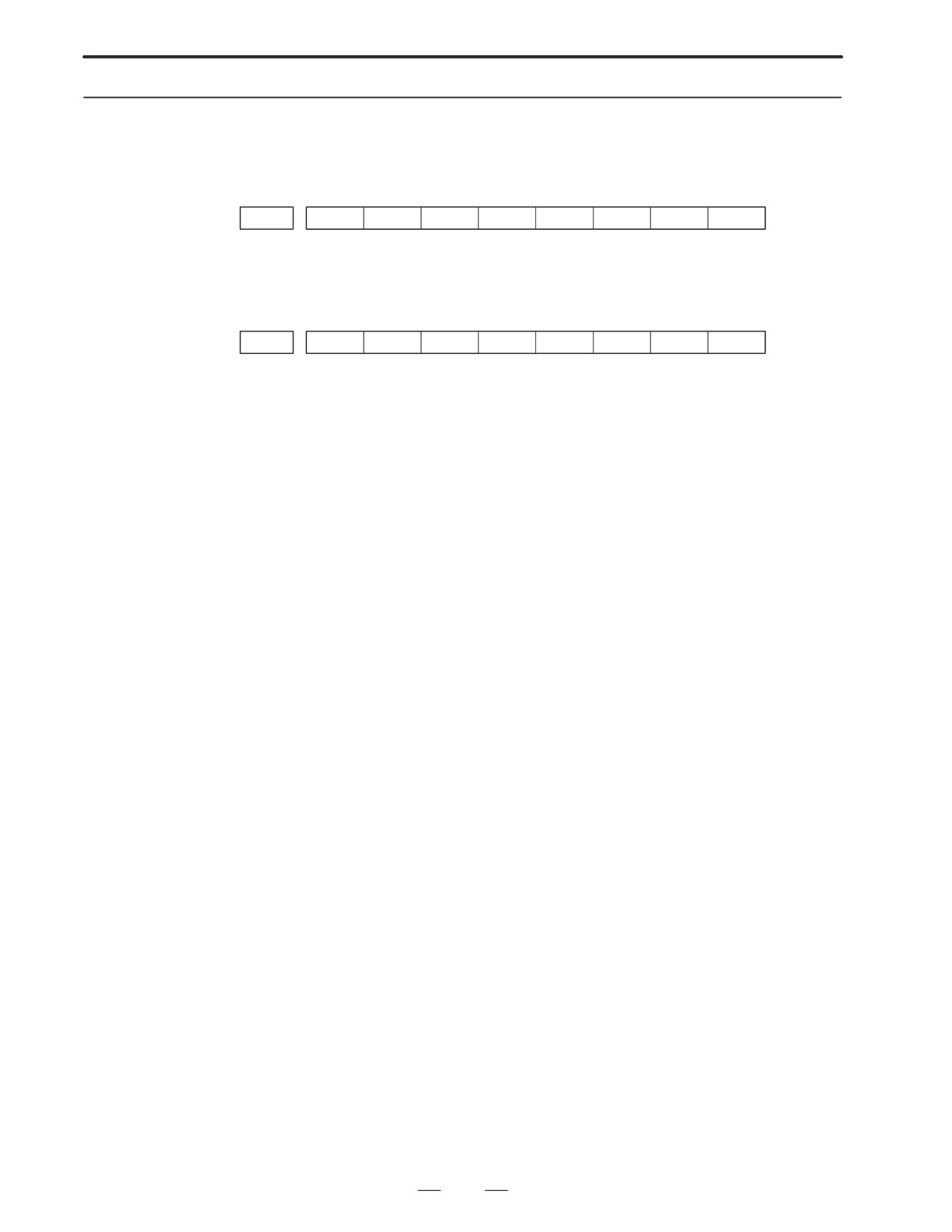
#7
#6
#5
#4
#3
#2
#1
#0
PRM
1002
DLZ
#1(DLZ)
0 : Dog is used for reference position return
l 1 : Dogless reference position setting
#7
#6
#5
#4
#3
#2
#1
#0
PRM
1006
ZMI
#5(ZMI)
0 : Reference position return and backlash initial direction is +.
1 : Reference position return and backlash initial direction is -.
After ZRN signal becomes 1, manual feed direction is always the
direction set by this parameter irrespective of an axis selection signal.
283
6. AC SPINDLE (SERIAL INTERFACE)
B-63005EN/01
AC SPINDLE (SERIAL INTERFACE)
6
This chapter outlines the serial interface and analog interface spindle
amplifiers and explains related parameters.
6.1
AC SPINDLE (SERIAL INTERFACE)
285
6.1.1
Outline of Spindle Control
285
6.1.2
Spindle Setting and Tuning Screen
288
6.1.3
Automatic Setting of Standard Parameters
296
6.2
AC SPINDLE (ANALOG INTERFACE)
297
6.2.1
Outline of Spindle Control
297
The following drawing number is indicated on the upper part of the
spindle unit of the serial interface spindle amplifier:
284

6. AC SPINDLE (SERIAL INTERFACE)
B-63005EN/01
6.1
AC SPINDLE (SERIAL
INTERFACE)
6.1.1
Outline of Spindle
Control
285
6. AC SPINDLE (SERIAL INTERFACE)
B-63005EN/01
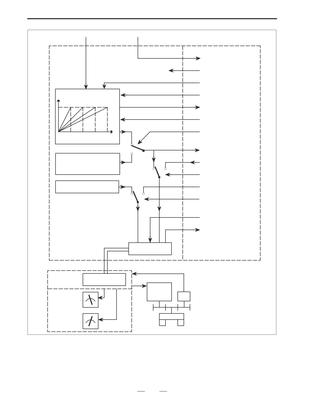
S instruction
M instruction
NC
PMC
M03,M04,M05,M19
FIN
*SSTP(Spindle stop)
SOVx( Spindle override)
Motor speed
SF,GR10,GR20,GR30
(For machining center)
GR1,GR2 (For lathe)
S
SOR( Orientation)
(PRM 3735X3752)
0
R010XR120
1
Orientation speed
(PRM 3705#1, 3732,
R01IXR12I
0
1
3706#5)
SIND
Output polarity
SGN(0=+,1=-)
(PRM 3706#7,6)
0
1
SSIN
*ESP,MRDY,
SFR,SRV,ORCM
etc.
SST, SDT, SAR, LDT1,
LDT2
ORAR, ALM etc.
Interface
function
Optical cable
Serial spindle
Interface
amplifier
function
Spindle
Operator’s
motor
panel
PC
Load meter
LM
Speed meter
Spindle
SM
286
6. AC SPINDLE (SERIAL INTERFACE)
B-63005EN/01
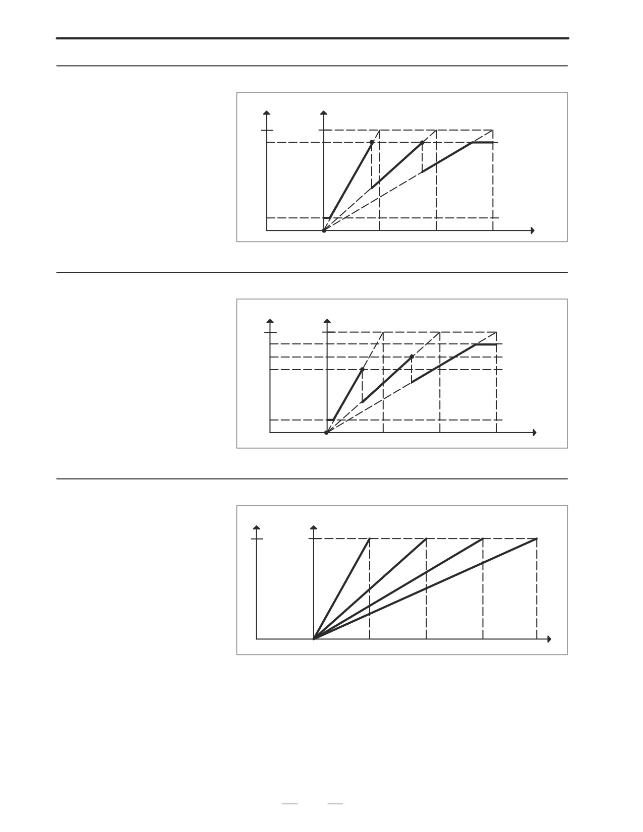
6.1.1.1
Method A of Gear
Output
Motor speed
Change for Machining
Center
4095
Max
PRM 3736
Gear 2
Gear 3
Gear 1
PRM 3735
0
S code
0 PRM 3741 PRM 3742 PRM 3743
6.1.1.2
Method B of Gear
Output
Motor speed
Change for Machining
4095
Max
Center(PRM 3705#2=1)
PRM 3736
Gear 1
Gear 2
Gear 3
PRM 3735
0
S code
0 PRM 3741 PRM 3742 PRM 3743
6.1.1.3
For Lathe
Output Motor speed
4095
Max
Gear 2
Gear 3
Gear 1
Gear 4
S code
0
0 PRM 3741 PRM 3742 PRM 3743 PRM 3744
287
6. AC SPINDLE (SERIAL INTERFACE)
B-63005EN/01
6.1.2
Spindle Setting and
Tuning Screen
6.1.2.1
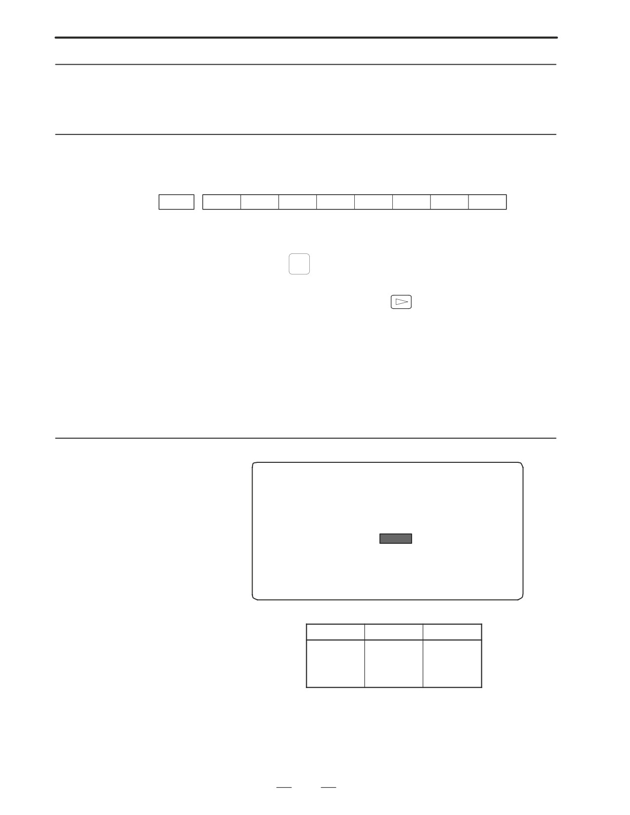
(1) Confirm the parameters
Display method
#7
#6
#5
#4
#3
#2
#1
#0
3111
SPS
Bit1 (SPS)
0 : The spindle tuning screen is not displayed.
l 1 : The spindle tuning screen is displayed.
(2) Press the
SYSTEM
key to select the screen for setting parameters and other
data.
(3) Press the continuous menu key
(4) Press the soft key [SP.PRM]. Then, the spindle setting and tuning
screen appears.
(5) The following screens are provided. These screens can be selected
using soft keys.
1) [SP.SET] : Spindle setting screen
2) [SP.TUN] : Spindle tuning screen
3) [SP.MON] : Spindle monitor screen
6.1.2.2
Spindle setting screen
SPINDLE SETTING
(1)GEAR SELECT
: 1
(2)SPINDLE
: S11
(PARAMETER)
(3)GEAR RATIO
50
(4)MAX SPINDLE SPEED
3000
(5)MAX MOTOR SPEED
6000
(6)MAX C AXIS SPEED
100
D Gear selection
The gear select status on the machine side is displayed.
Indication
CTH1
CTH2
1
0
0
2
0
1
3
1
0
4
1
1
D Spindle
Select a spindle for which data is to be set.
S11: Main spindle amplifier for the 1st spindle
S12: Subspindle amplifier for the 1st spindle
S21: Main spindle amplifier for the 2nd spindle
S22: Subspindle amplifier for the 2nd spindle
288
6. AC SPINDLE (SERIAL INTERFACE)
B-63005EN/01
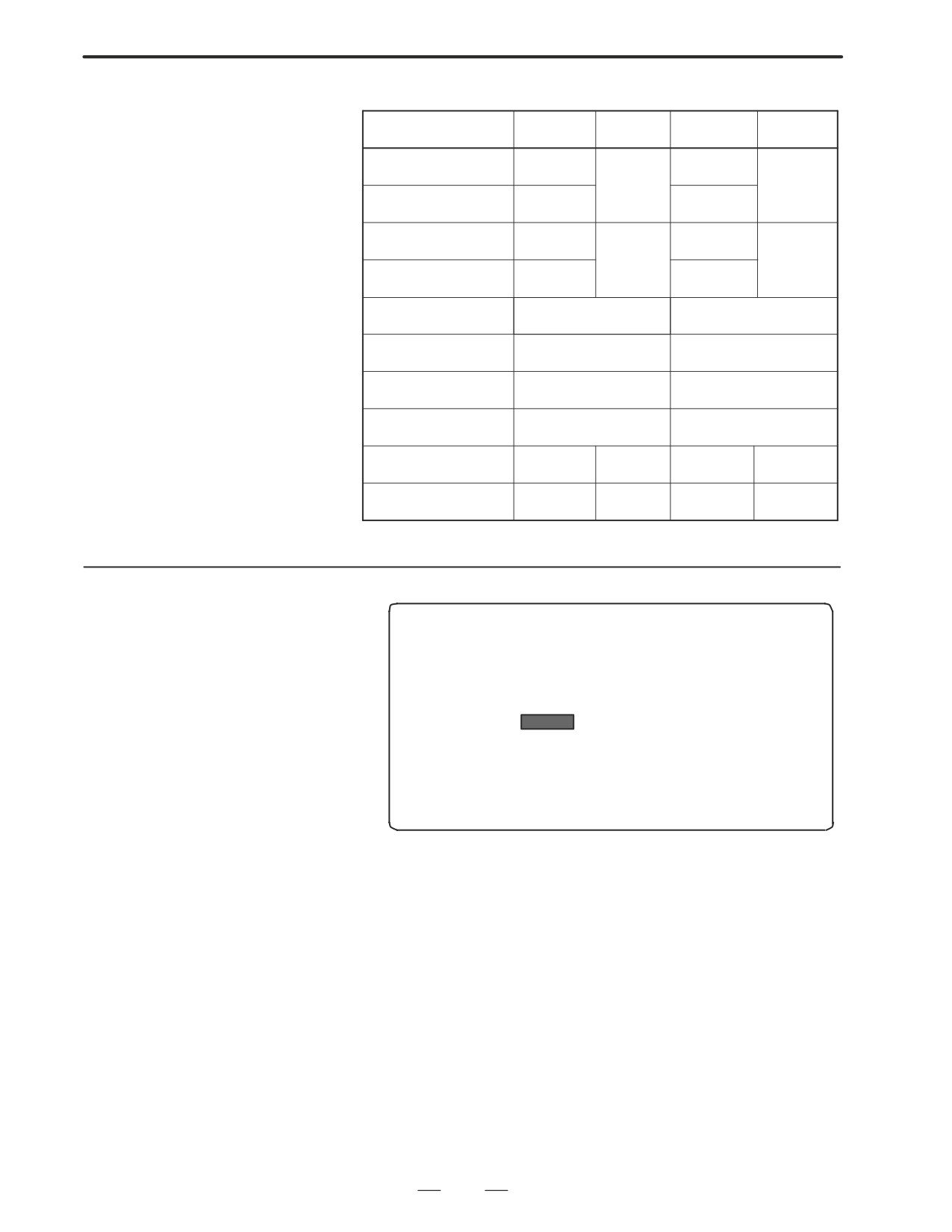
D Parameters
S11:1st Main
S12:1st Sub S21:2nd Main
S22:2nd Sub
Gear ratio(HIGH)
4056
4056
4216
4216
Gear ratio(MIDIUM HIGH)
4057
4057
Gear ratio(MIDIUM LOW)
4058
4058
4217
4217
Gear ratio(LOW)
4059
4059
Max. spindle speed
3741
3741
(gear1)
Max. spindle speed
3742
3742
(gear2)
Max. spindle speed
3743
3743
(gear3)
Max. spindle speed
3744
3744
(gear4)
Max. motor speed
4020
4196
4020
4196
Max. C axis speed
4021
None
4021
None
6.1.2.3
Spindle tuning screen
SPINDLE TUNING
OPERATION
: SPEED CONTROL
GEAR SELECT
: 1
SPINDLE
: S11
(PARAMETER)
(MONITOR)
PROP.GAIN
20
MOTOR SPEED
100
INT.GAIN
50
SPINDLE SPEED 150
LOOP GAIN
3000
POS ERR S1
100
MOTOR VOLT
30
POS ERR S2
103
TIME CONST
100
SYN.ERR
3
REF. SHIFT
2046
D Operation mode
1
: Normal operation
2
: Orientation
3
: Synchronization control
4
: Rigid tapping
5
: Cs contour control
6
: Spindle positioning control
289