FANUC Series 16i / 18i / 160i / 180i - Model A. Maintenance Manual (B-63005EN/01) - page 9
3. INPUT AND OUTPUT OF DATA
B-63005EN/01
Reading a file
Procedure
1
Press the EDIT switch on the machine operator’s panel.
2
Press function key PROG.
3
Press the rightmost soft key
(continuous menu key).
4
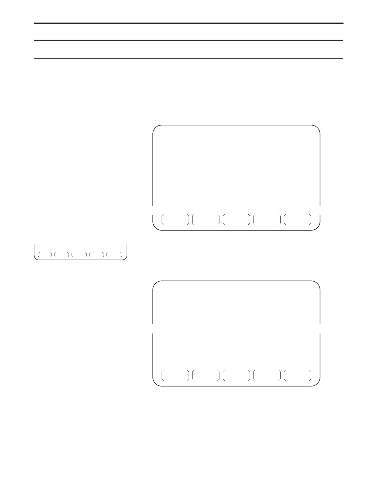
Press soft key [CARD]. Then, the screen shown below is displayed.
DIRECTORY (M-CARD)
O0034 N00045
No. FILE NAME
SIZE
DATE
0001
O1000
123456
96/07/10
0002
O1001
118458
96/07/30
0003
O0002
113250
96/07/30
0004
O2000
173456
96/07/31
0005
O2001
113444
96/07/31
0006
O3001
118483
96/08/02
0007
O3300
111406
96/08/05
0008
O3400
112420
96/07/31
0009
O3500
117460
96/07/31
~
~
PROG
DIR +
(OPRT)
5
Press soft key [(OPRT)].
F SRH F READ N READ PUNCH DELETE
6
To specify a file number, press soft key [F READ]. The screen shown
below is displayed.
DIRECTORY (M-CARD)
O0001 N00010
No. FILE NAME
COMMENT
0019
O1000
(MAIN PROGRAM)
0020
O1010
(SUBPROGRAM-1)
0021
O1030
(COMMENT
)
~
~
READ
FILE NAME=20
PROGRAM No.=120
>
EDIT
15:40:21
***
****
***
****
F NAME
O SET
STOP
CAN
EXEC
7
Enter file number 20 from the MDI panel, then set the file number by
pressing soft key [F SET]. Next, enter program number 120, then set
the program number by pressing soft key [O SET]. Then, press soft
key [EXEC].
⋅
File number 20 is registered as O0120 in the CNC.
⋅
Set a program number to register a read file with a separate O
number. If no program number is set, the O number in the file name
column is registered.
230

3. INPUT AND OUTPUT OF DATA
B-63005EN/01
8
To specify a file with its file name, press soft key [N READ] in step 6
above. The screen shown below is displayed.
DIRECTORY (M-CARD)
O0001 N00010
No. FILE NAME
COMMENT
0012
O0050
(MAIN PROGRAM)
0013
TESTPRO
(SUB PROGRAM-1)
0014
O0060
(MACRO PROGRAM)
~
~
READ
FILE NAME
=TESTPRO
PROGRAM No. =1230
>
EDIT
15:40:21
***
****
***
****
F NAME
O SET
STOP
CAN
EXEC
9
To register file name TESTPRO as O1230, enter file name TESTPRO
from the MDI panel, then set the file name with soft key [F NAME].
Next, enter program number 1230, then set the program number with
soft key [O SET]. Then, press soft key [EXEC].
231
3. INPUT AND OUTPUT OF DATA
B-63005EN/01
Writing a file
Procedure
1
Press the EDIT switch on the machine operator’s panel.
2
Press function key
PROG
3
Press the rightmost soft key
(continuous menu key).
4
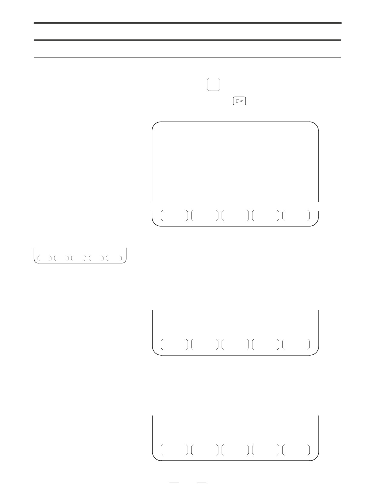
Press soft key [CARD]. The screen shown below is displayed.
DIRECTORY (M-CARD)
O0034 N00045
No. FILE NAME
SIZE
DATE
0001
O1000
123456
96/07/10
0002
O1001
118458
96/07/30
0003
O0002
113250
96/07/30
0004
O2000
173456
96/07/31
0005
O2001
113444
96/07/31
0006
O3001
118483
96/08/02
0007
O3300
111406
96/08/05
0008
O3400
112420
96/07/31
0009
O3500
117460
96/07/31
~
~
PROG
DIR +
(OPRT)
5
Press soft key [(OPRT)].
6
Press soft key [PUNCH].
F SRH F READ N READ PUNCH DELETE
7
Enter a desired O number from the MDI panel, then set the program
number with soft key [O SET].
When soft key [EXEC] is pressed after the setting shown below has
been made, for example, the file is written under program number
O1230.
~
~
PUNCH
FILE NAME
=
PROGRAM No. =1230
>
EDIT
***
****
***
****
15:40:21
F NAME
O SET
STOP
CAN
EXEC
8
In the same way as for O number setting, enter a desired file name
from the MDI panel, then set the file name with soft key [F SET].
When soft key [EXEC] is pressed after the setting shown below has
been made, for example, the file is written under program number
O1230 and file name ABCD12.
~
~
PUNCH
FILE NAME
=ABCD12
PROGRAM No. =1230
>
EDIT
***
****
***
****
15:40:21
F NAME
O SET
STOP
CAN
EXEC
232
3. INPUT AND OUTPUT OF DATA
B-63005EN/01
Deleting a file
Procedure
1
Press the EDIT switch on the machine operator’s panel.
2
Press function key
PROG
3
Press the rightmost soft key
(continuous menu key).
4
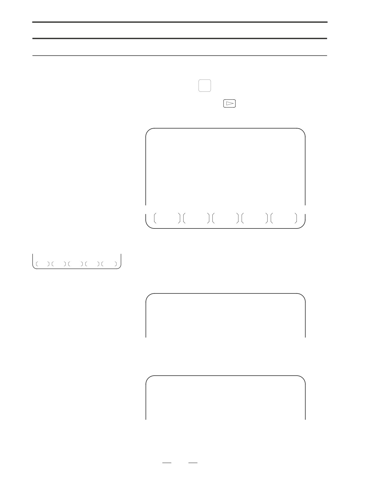
Press soft key [CARD]. The screen shown below is displayed.
DIRECTORY (M-CARD)
O0034 N00045
No. FILE NAME
SIZE
DATE
0001
O1000
123456
96/07/10
0002
O1001
118458
96/07/30
0003
O0002
113250
96/07/30
0004
O2000
173456
96/07/31
0005
O2001
113444
96/07/31
0006
O3001
118483
96/08/02
0007
O3300
111406
96/08/05
0008
O3400
112420
96/07/31
0009
O3500
117460
96/07/31
~
~
PROG
DIR +
(OPRT)
5
Press soft key [(OPRT)].
6
Set the number of the desired file with soft key [DELETE], then press
F SRH F READ N READ PUNCH DELETE
soft key [EXEC]. The file is deleted, and the directory screen is
displayed again.
When file number 21 is deleted
DIRECTORY (M-CARD)
O0034 N00045
No. FILE NAME
COMMENT
0019
O1000
(MAIN PROGRAM)
0020
O1010
(SUBPROGRAM-1)
0021
O1020
(COMMENT
)
0022
O1030
(COMMENT
)
~
~
File name O1020 is deleted.
DIRECTORY (M-CARD)
O0034 N00045
No. FILE NAME
COMMENT
0019
O1000
(MAIN PROGRAM)
0020
O1010
(SUBPROGRAM-1)
0021
O1020
(COMMENT
)
0022
O1030
(COMMENT
)
~
~
File number 21 is assigned to the next file name.
233
3. INPUT AND OUTPUT OF DATA
B-63005EN/01
Batch input/output with a memory card
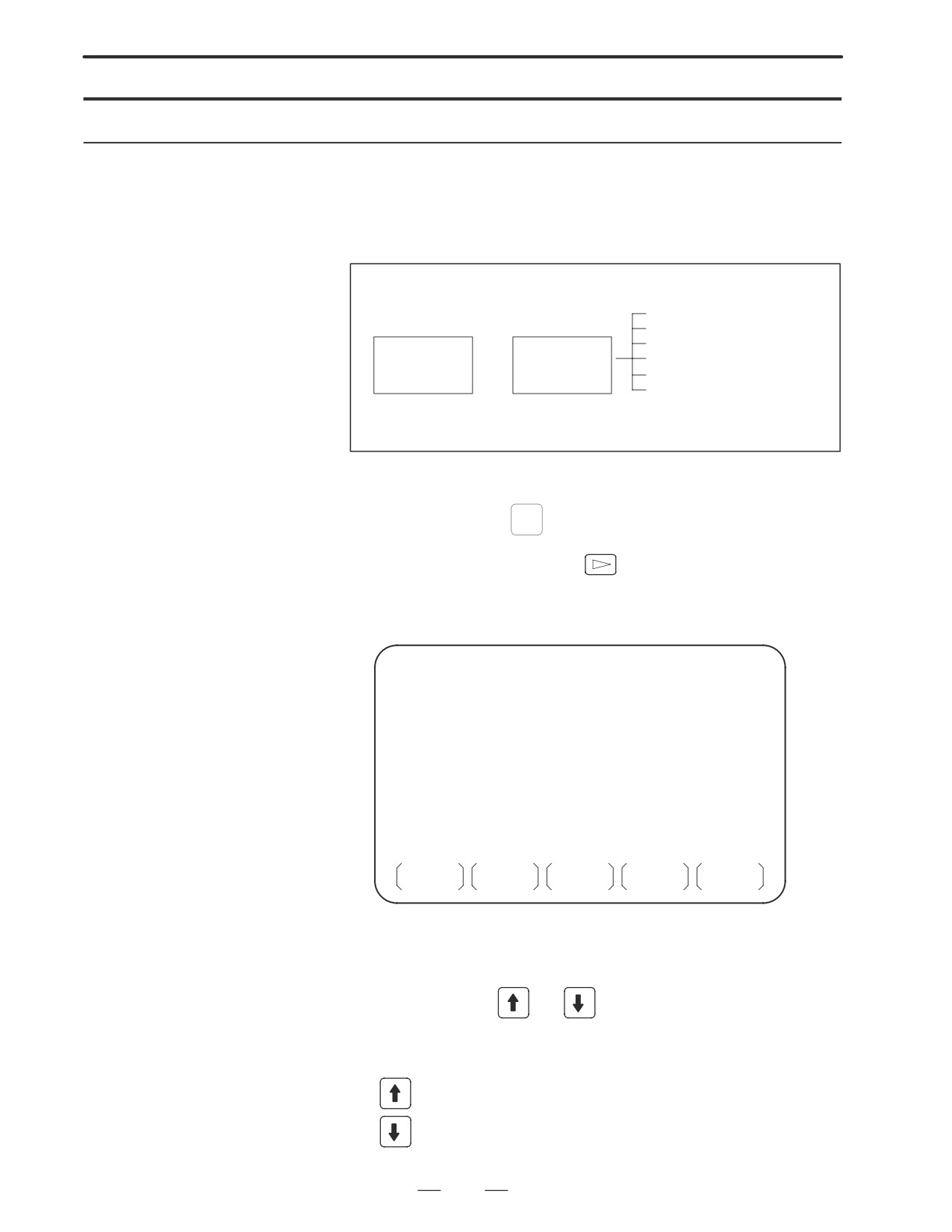
On the ALL IO screen, different types of data including part programs,
parameters, offset data, pitch error data, custom macros, and workpiece
coordinate system data can be input and output using a memory card; the
screen for each type of data need not be displayed for input/output.
Data item name
Part program
Parameter
Offset data
Memory card
²
ALL IO screen
Pitch error data
Custom macro
³
Workpiece coordinate system
data
(additional coordinate systems)
Procedure
1
Press the EDIT switch on the machine operator’s panel.
SYSTEM
2
Press function key
3
Press the rightmost soft key
(continuous menu key) several
times.
4
Press soft key [ALL IO]. The screen shown below is displayed.
READ/PUNCH (PROGRAM)
O0001 N00001
No. FILE NAME
SIZE
DATE
* 0001
O0222
332010
96-04-06
0002
O1003
334450
96-05-04
0003
MACROVAR.DAT 653400
96-05-12
0004
O0002
341205
96-05-13
[PROGRAM]
O0001
O0002
O0003
O0005
O0100
O0020
O0006
O0004
O0110
O0200
O2200
O0441
O0330
>
EDIT
10:07:37
***
****
***
****
PROG
PARAM
OFFSET
(OPRT)
Upper part : Directory of files on the memory card
Lower part : Directory of registered programs
5
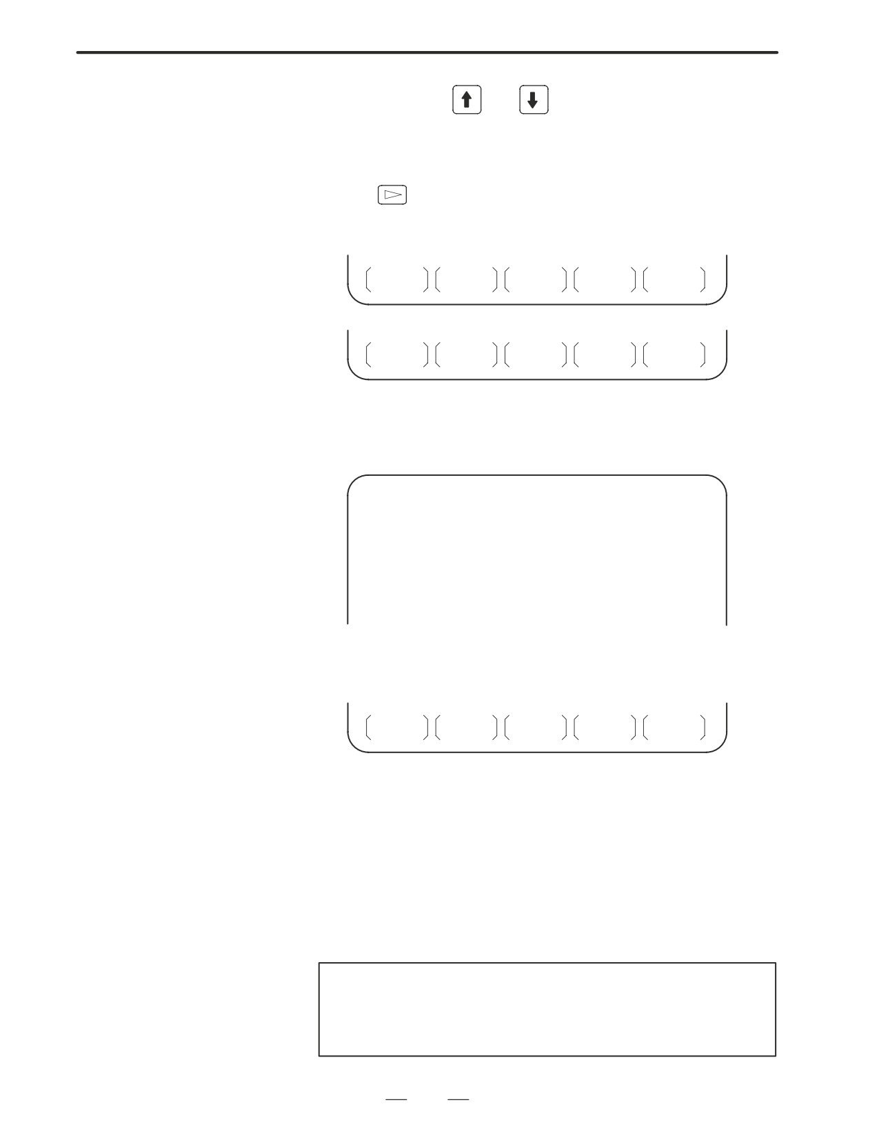
With cursor keys
and
, the user can choose between upper
part scrolling and lower part scrolling. (An asterisk (*) displayed at
the left edge indicates the part for which scrolling is possible.)
: Used for memory card file directory scrolling.
: Used for program directory scrolling.
234
3. INPUT AND OUTPUT OF DATA
B-63005EN/01
6
With page keys
and
, scroll through the file directory or
program directory.
7
When this screen is displayed, the program data item is selected. The
soft keys for other screens are displayed by pressing the rightmost soft
key
(continuous menu key). Soft key [M-CARD] represents a
separate memory card function for saving and restoring system RAM
data.
(See Sections 3.7.7 and Section NO TAG.)
MACRO
PITCH
WORK
(OPRT)
M-CARD
(OPRT)
When a data item other than program is selected, the screen displays only
a file directory.
A data item is indicated, in parentheses, on the title line.
READ/PUNCH (PARAMETER)
O0001 N00001
No. FILE NAME
SIZE
DATE
0001
O0222
332010
96/04/06
0002
O1003
334450
96/05/04
0003
MACROVAR.DAT
653400
96/05/12
0004
O0003
334610
96/05/04
0005
O0001
334254
96/06/04
0006
O0002
333750
96/06/04
0007
CNCPARAM.DAT
334453
96/06/04
~
~
8
Display the following soft keys with soft key [(OPRT)].
F SRH
F READ
N READ
PUNCH
DELETE
The operation of each function is the same as on the directory (memory
card) screen. Soft key [O SET], used for program number setting, and the
”PROGRAM NUMBER =” indication are not displayed for data items
other than program.
[F SRH]
: Finds a specified file number.
[F READ]
: Reads a specified file number.
[PUNCH]
: Writes a file.
[N READ] : Reads a file under a specified file name.
[DELETE] : Deletes a specified file number.
NOTE
With a memory card, RMT mode operation and the
subprogram call function (based on the M198 command)
cannot be used.
235

3. INPUT AND OUTPUT OF DATA
B-63005EN/01
Error codes
Memory card error codes
Code
Meaning
102
The memory card does not have sufficient free space.
105
No memory card is mounted.
106
A memory card is already mounted.
110
The specified directory cannot be found.
111
There are too many files under the root directory to allow a
directory to be added.
114
The specified file cannot be found.
115
The specified file is protected.
117
The file has not yet been opened.
118
The file is already open.
119
The file is locked.
122
The specified file name is invalid.
124
The extension of the specified file is invalid.
129
A non-corresponding function was specified.
130
The specification of a device is invalid.
131
The specification of a pathname is invalid.
133
Multiple files are open at the same time.
135
The device is not formatted.
140
The file has the read/write disabled attribute.
236
B-63005EN/01
4.INTERFACE BETWEEN NC AND PMC
INTERFACE BETWEEN NC AND PMC
4
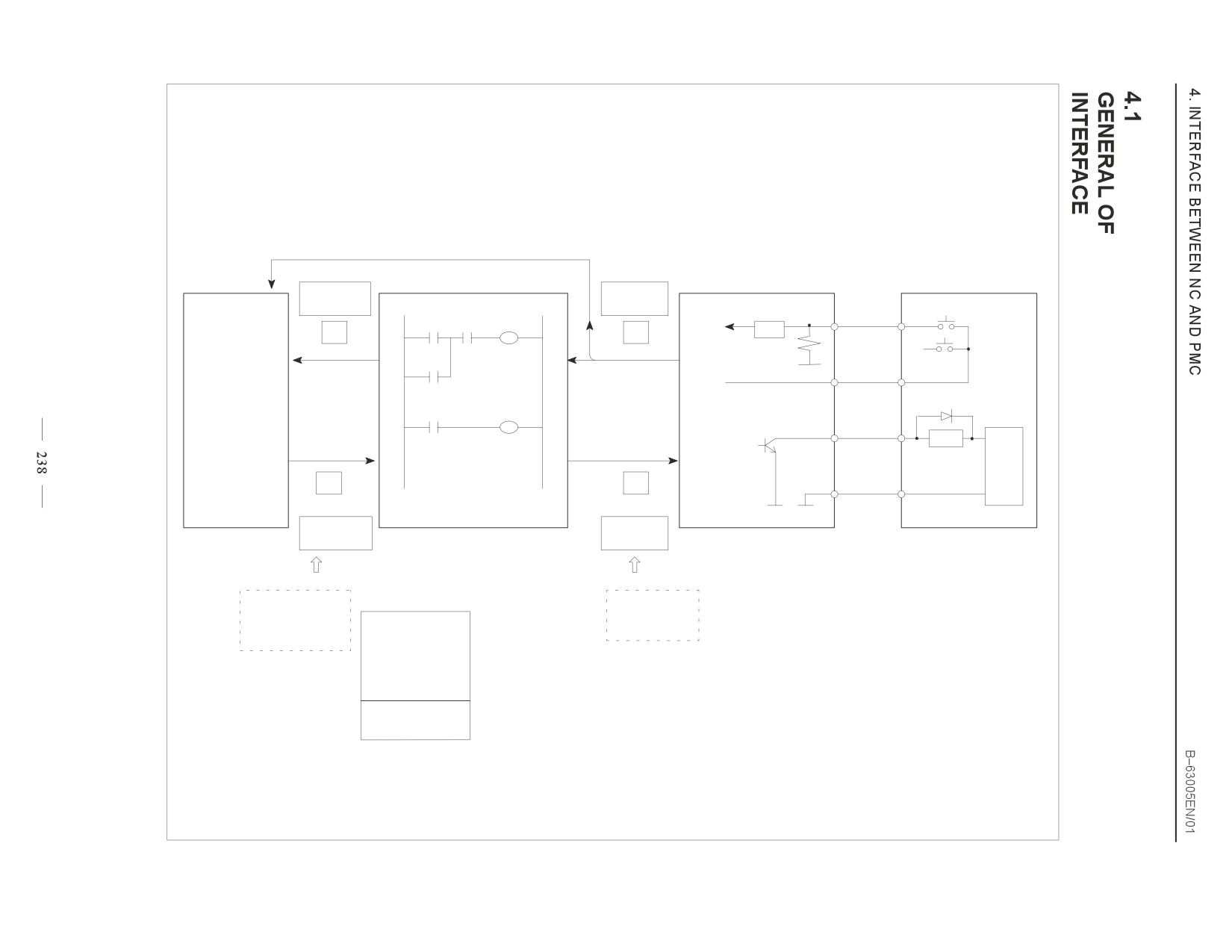
This chapter describes the signals between the machine operator’s panel,
magnetics cabinet and the PMC, connection of the signals between PMC
and CNC, and confirmation method of on/off state of these signals.
It also describes system configuration of PMC, parameters of PMC,
ladder and how to display time chart of the signals on the screen.
It also describes a method of inputting/outputting PMC parameters to an
external device.
4.1
GENERAL OF INTERFACE
238
4.2
SPECIFICATION OF PMC
239
4.3
PMC SCREEN
245
4.4
LIST OF SIGNALS BY EACH MODE
264
237
PMCDGN Input
Contacts
High-speed processing signal
*DEC
a *ESP, SKIP, ESKIP, XAE, YAE, ZAE (M series)
[0]
0V
Open
*DEC
a *ESP, SKIP, ESKIP, XAE, ZAE, +MIT a (T series)
[1]
. . 24V
Close
NC
PMCDGN
PMCDGN *
DI/DO
PMC-RB/RC
MT (Machine Tool builder)
G 0000 ~ 0191
X 0000 ~0127
ST1 DOOR
ST
ST1
G
X
RV
X0.1
X0.0
G007.2
ST2
ST2
0V
+24E
X5.7
Power
STL
STL
supply
F0.5
Y0.1
Load
+
F
Y
-
PMCDGN
PMCDGN *
0V
0V
F 0000 ~ 0141
Y 0000 ~ 0127
PMCDGN
Tr
Output
Load
[0]
Off
24V
Off
FANUC decides
PMC address
MTB decides
addresses
addresses
[1]
On
0V
On
and signals
Internal relay
and signals
correspondence
Variable timer
Counter
*1) If I/O unit is added:
Data table
Message display
1st sheet
Keep relay
X1000.0 to X1019.7
Y1000.0 to Y1014.7
2nd sheet
System reserve
X1020.0 to X1039.7
area
Y1020.0 to Y1034.7
B-63005EN/01
4.INTERFACE BETWEEN NC AND PMC
4.2
SPECIFICATION OF
PMC
4.2.1
Specification
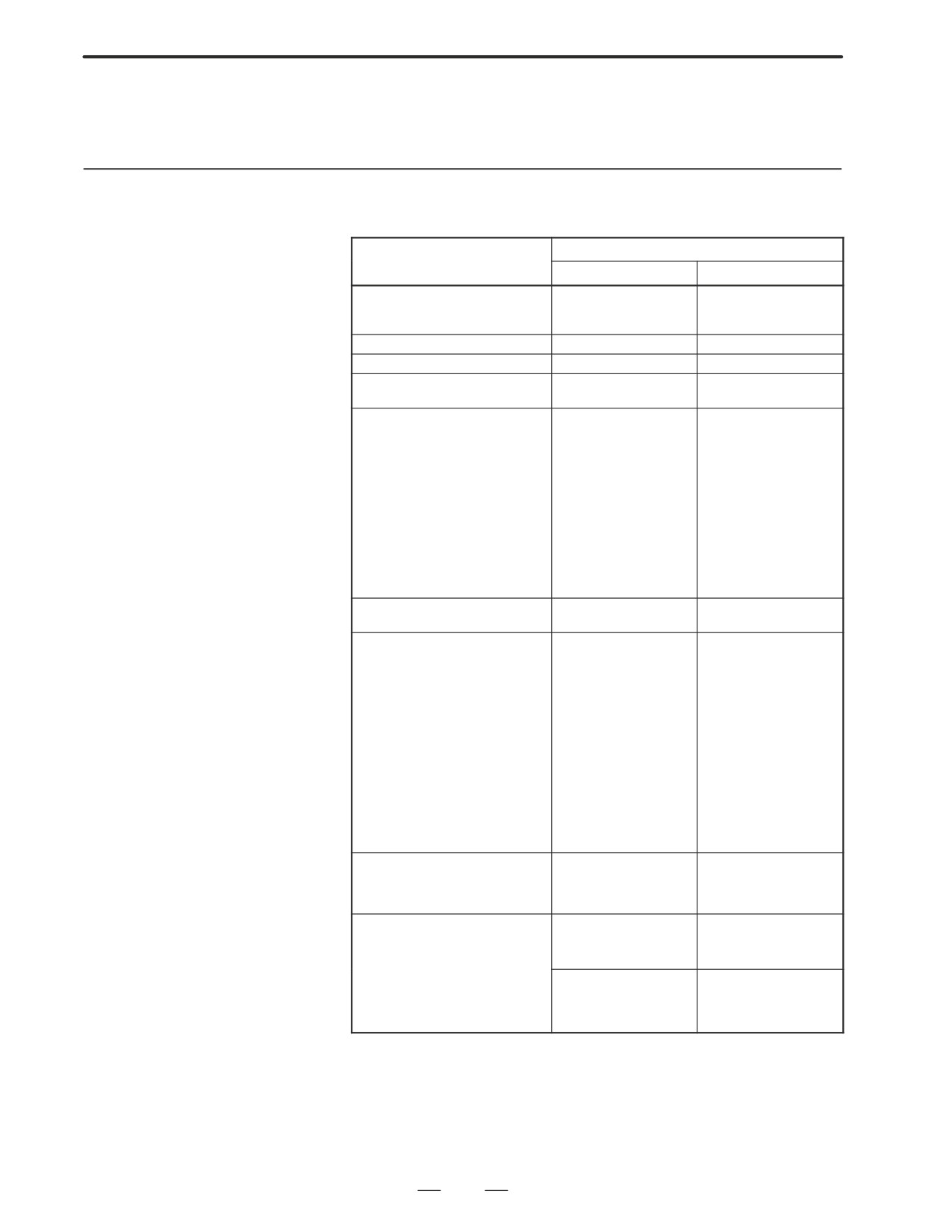
Series 16i-MODEL A/Series 18i-MODEL A
Model
PMC-RB5
PMC-RB6
Programming method language
Ladder
Ladder
C-language
Step sequence
C-language
Number of ladder level
2
2
Level-1 Cycle Time
8 ms
8 ms
Basic Instruction Execution Time
0.085
0.085
(us/step)
(us/step)
Program capacity
D Ladder (step)
Approx. 3,000
Approx. 3,000
Approx. 5,000
Approx. 5,000
Approx. 8,000
Approx. 8,000
Approx. 12,000
Approx. 12,000
Approx. 16,000
Approx. 16,000
Approx. 24,000
Approx. 24,000
Approx. 32,000
D Symbol/Comment
1 to 128KB
1 to 128KB
D Message
0.1 to 64KB
0.1 to 64KB
D Language only
Instuction (Basic)
14 kinds
14 kinds
(Functional)
67 kinds
67 kinds
Intemal relay
(R)
1618 byte
3200 byte
Message request
(A)
25 byte
125 byte
Non-volatile
D Var. Timer
(T)
80 byte
300 byte
D Counter
(C)
80 byte
200 byte
D Keep relay
(K)
20 byte
50 byte
D Data table
(D)
3000 byte
8000 byte
Subprogram
(P)
512 programs
2000 programs
Label
(L)
9999 labels
9999 labels
Fixed timer
Timer No. 100
Timer No. 100
devices specified
devices specified
Input/output
D I/O link
(I) Max.
1024 points max.
1024 points max.
(O) Max.
1024 points max.
1024 points max.
Sequence program storage media
Flash ROM
Flash ROM
Ladder
128KB
128KB
256KB
256KB
C language
256KB
256KB
512KB
512KB
1MB
1MB
2MB
2MB
239
4. INTERFACE BETWEEN NC AND PMC
B-63005EN/01
4.2.2
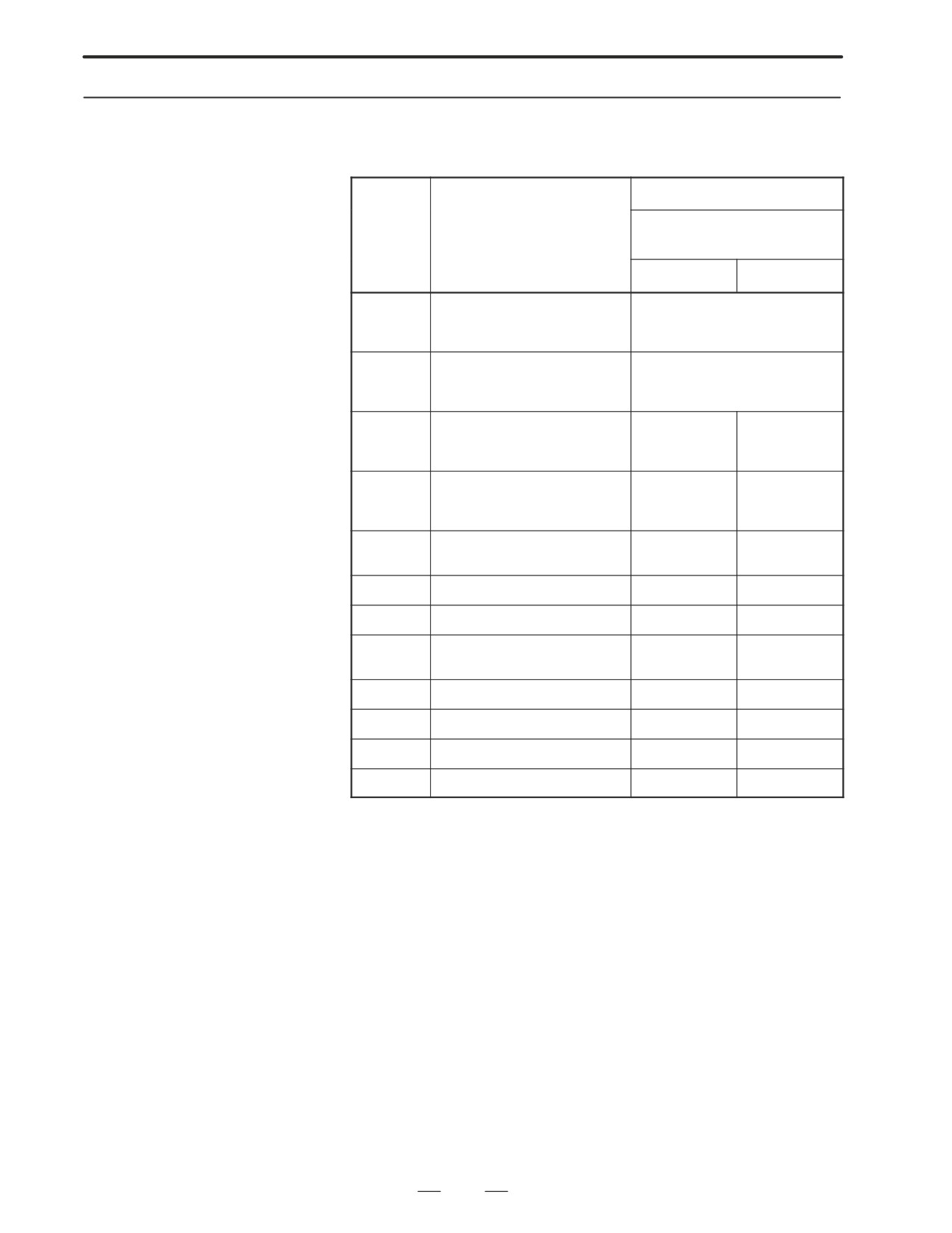
Address
Model
Series 16i-MODEL
Character
Signal description
4/Series 18i-MODEL
PMC-RB5
PMC-RB6
X0 to X127
Input signal from the machine to
X
X1000 to X1019
the PMC (MT to PMC)
X1020 to 1039
Y0 to Y127
Output signal from the PMC to the
Y
Y1000 to Y1014
machine (PMC to MT)
Y1020 to Y1034
F
Input signal from the NC to the
F0 to F255
F0 to F511
PMC
F1000 to F1255
F1000 to F1511
(NC to PMC)
F2000 to F2511
G
Output signal from the PMC to the
G0 to G255
G0 to G511
NC
G1000 to G1255
G1000 to G1511
(PMC to NC)
G2000 to G2511
R
Internal relay
R0 to R1499
R0 to R2999
R9000 to R9117
R9000 to R9199
A
Message request signal
A0 to A24
A0 to A124
C
Counter
C0 to C79
C0 to C199
K
Keep relay
K0 to K19
K0 to K39
K900 to K909
T
Data table
T0 to T79
T0 to T299
D
Variable timer
D0 to D2999
D0 to D7999
L
Label number
L1 to L9999
L1 to L9999
P
Subprogram number
P1 to P512
P1 to P2000
240
B-63005EN/01
4.INTERFACE BETWEEN NC AND PMC
4.2.3
Built-in Debug
Function
Contents
Function
Display of sequence program
Dynamic display of ladder diagram
Diagnostic function
S Title data display
S signal status (symbol can be displayed)
S PMC alarm display
S Signal trace
S Memory contents display
S Signal waveform display
S Task status display (PMC-RC3/RC4 only)
S I/O connection status display
Setting and displaying data
S Timer
S Counter
S Keep relay
S Data table
Sequence program edit function
Ladder diagram editing
(A ladder edit module is required It is not required
when PMC language board is used.)
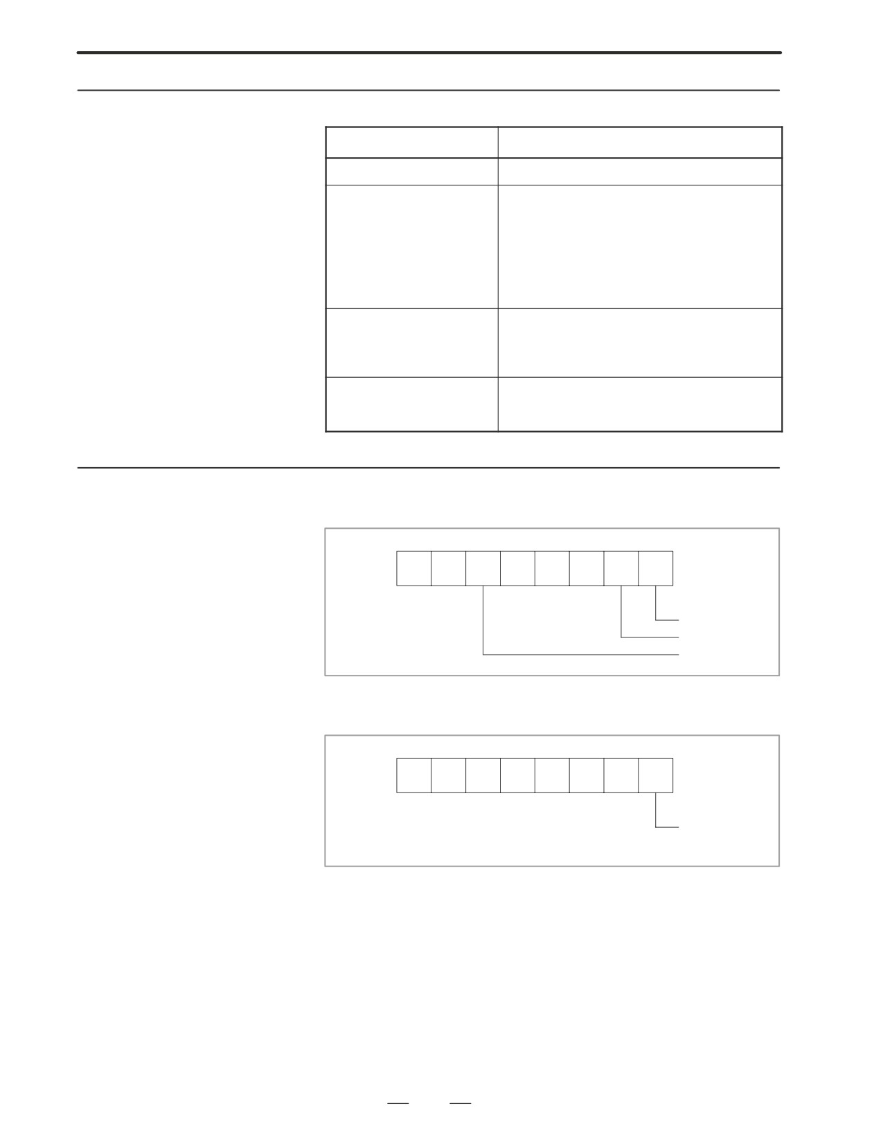
4.2.4
(1) R9000 (Operation output register for the ADD, SUB, MULB, DIVB,
and COMPB functional instructions)
System Reserve Area
of Internal Relay
#7
#6
#5
#4
#3
#2
#1
#0
R9000
V
N
Z
Operation result
register
Zero
Sign is minus
Overflow
(2) R9000 (Error output for the EXIN, WINDR, WINDW, MMCWR,
MMCWW, MMC3R, and MMC3W functional instructions)
#7
#6
#5
#4
#3
#2
#1
#0
R9000
The instruc-
tion ended in
error.
241
4. INTERFACE BETWEEN NC AND PMC
B-63005EN/01
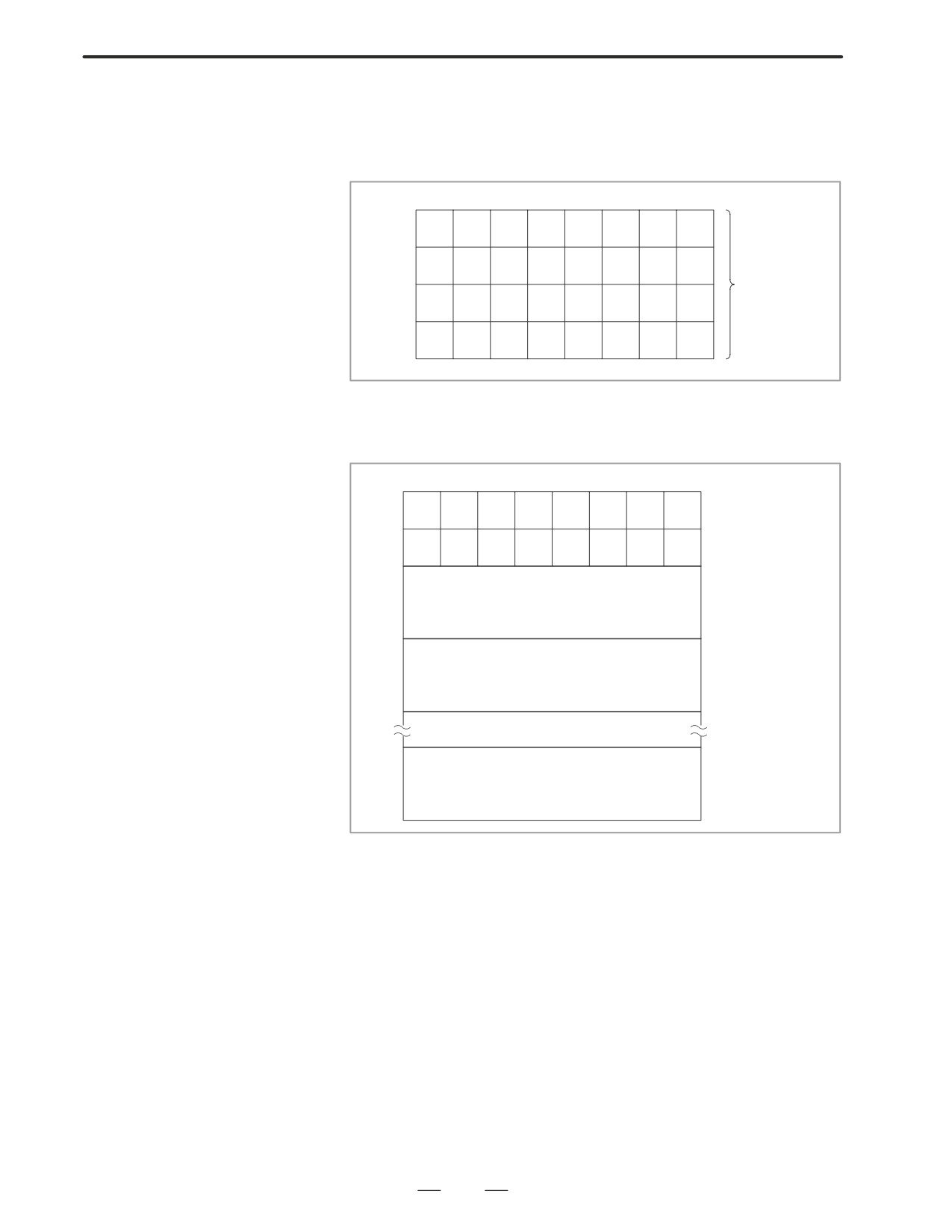
(3) R9002 to R9005 (Operation output registers for the DIVB functional
instruction)
The data remaining after the DIVB functional instruction is executed
in output.
#7
#6
#5
#4
#3
#2
#1
#0
R9002
R9003
Register for
remainder
R9004
(used by DIVB
instruction)
R9005
(4) R9100 to R9117 (Interface area for the FNC9x functional instruction)
The area is provided as an interface between the FNC9x functional
instruction to be executed and a desired function.
#7
#6
#5
#4
#3
#2
#1
#0
Contents of the com-
R9100
97
96
95
94
93
92
91
90
mand to be executed
Data output when
R9101
97
96
95
94
93
92
91
90
the processing is
R9102
completed
Addresses of the control data for SUB90
R9103
R9104
Addresses of the control data for SUB91
R9105
R9116
Addresses of the control data for SUB97
R9117
242
B-63005EN/01
4.INTERFACE BETWEEN NC AND PMC
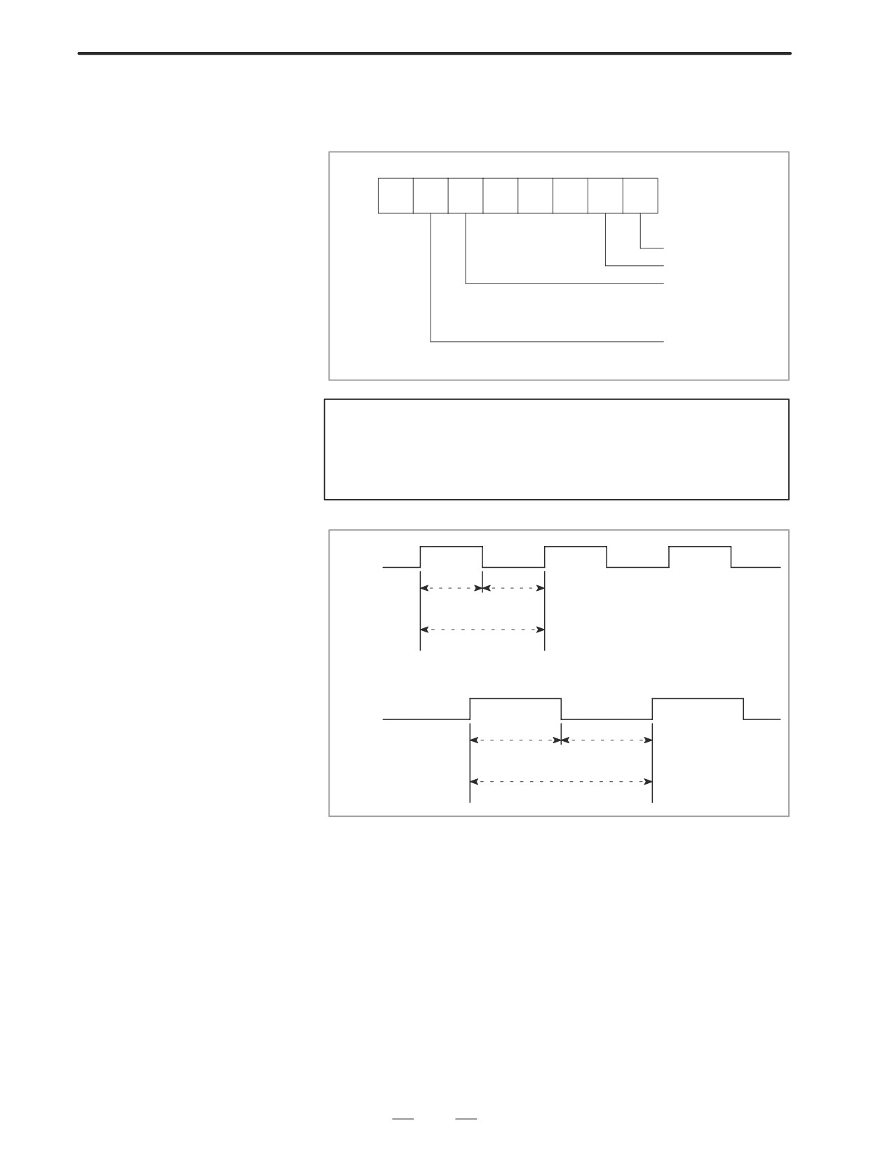
(5) R9091 (System timer)
4 signals can be used as system timer.
The specifications of every signal are as following.
#7
#6
#5
#4
#3
#2
#1
#0
R9091
always OFF
always ON
Cyclic signal of 200
ms (104 ms ON, 96
ms OFF)
Cyclic signal of 1 se-
cond. (504 ms ON,
496 ms OFF)
CAUTION
Each signal is initially off. R9091.0 and R9091.1 are set
cyclically at the beginning of the first ladder level.
Each signal (ON-OFF signal) has an accuracy of "8 ms.
R9091.5
104ms
96ms
200ms
R9091.6
504ms
496ms
1s
243
4. INTERFACE BETWEEN NC AND PMC
B-63005EN/01
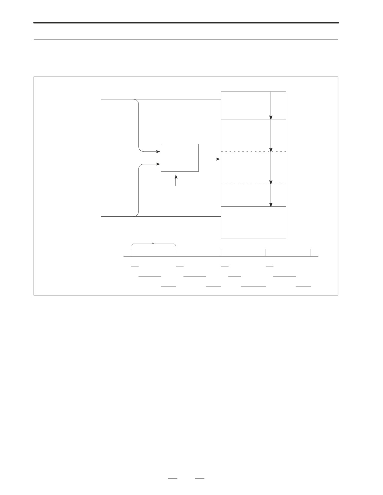
4.2.5
Execution Period of
PMC
Sequence program
1st level
From NC
(High-speed se-
(1)
quence)
END1
2nd level
(Normal sequence)
(2)-1
Synchronized
buffer
(2)-2
Head of 2nd level
(2)-n
END2
3rd level
From MT
(Display sequence)
(PMC-RC/RC3/
RC4 only)
END3
8msec
Period
(1)
(1)
(1)
(1)
1st level
(2)-1
(2)-2
(2)-n
(2)-1
2nd level
3rd level
244
B-63005EN/01
4.INTERFACE BETWEEN NC AND PMC
4.3
PMC SCREEN
4.3.1
1. Press
SYSTEM
Display Method
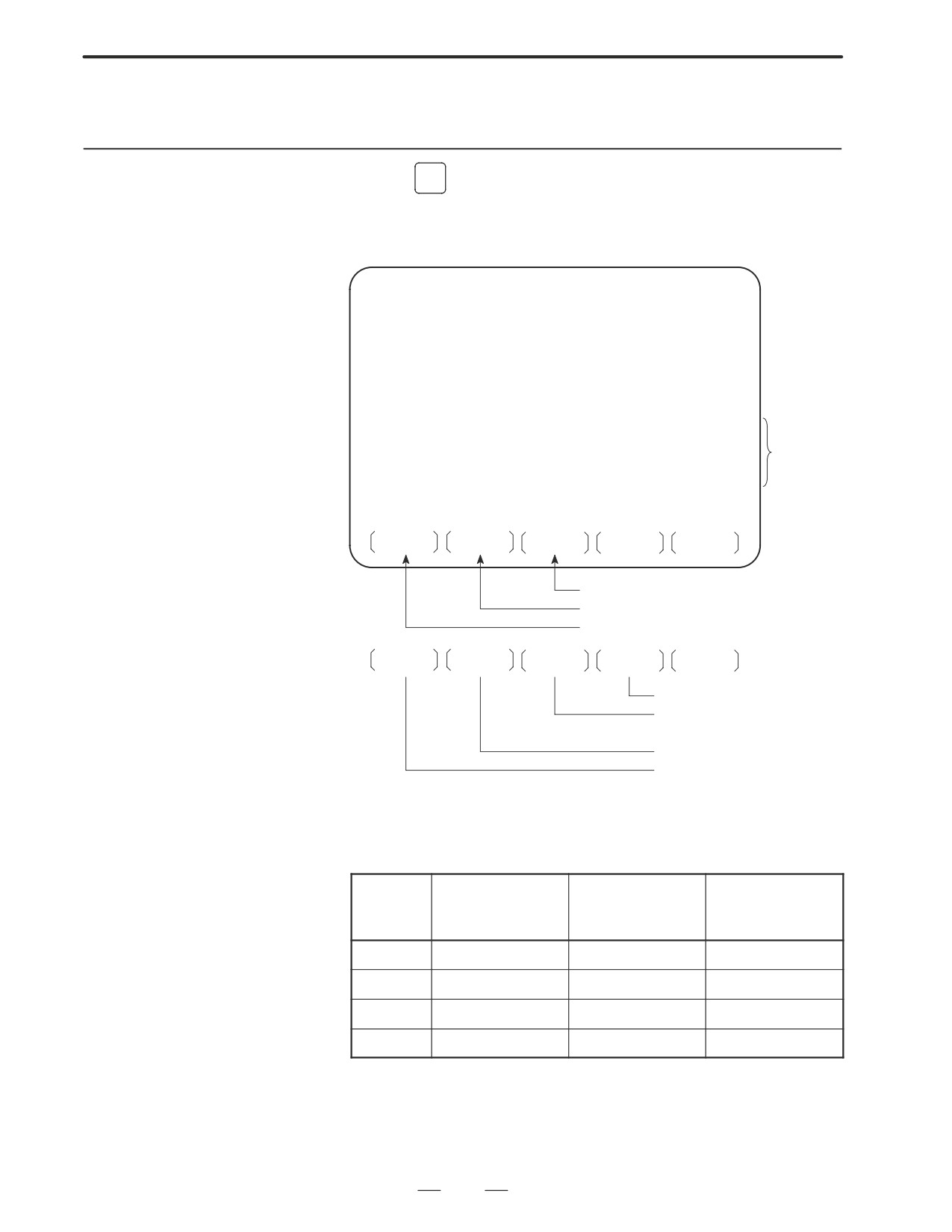
2. Press soft key [PMC], then PMC screen is displayed and the following
soft keys are displayed:
PMC CONTROL SYSTEM MENU
MONIT RUN
SELECT ONE OF FOLLOWING SOFT KEYS
PMCLAD
: DYNAMIC LADDER DISPLAY
PMCDGN
: DIAGNOSIS FUNCTION
PMCPRM
: PARAMETER (T/C/K/D)
RUN/STOP
: RUN/STOP SEQUENCE PROGRAM
When
EDIT
: EDIT SEQUENCE PROGRAM
built-in
program-
I/O
: I/O SEQUENCE PROGRAM
mer is run-
SYSPRM
: SYSTEM PARAMETER
ning.
MONIT
: PMC MONITOR
PMCLAD
PMCDGN
PMCPRM
System parameter screen
Status display of PMC I/O signal
Dynamic display of sequence program
STOP
EDIT
I/O
SYSPRM
MONIT
System parameter screen
Input/output of sequence pro-
gram
Editing sequence program
RUN/STOP of sequence
The no. of menus to be displayed changes depending on presence/
absence of built-in programmer.
PMC-RB5/RB6
PMC-RB5/RB6
PMC-RB5/RB6
(Without memory
(With memory
(With C language
card for editing)
card for editing)
board)
RUN/STOP
f
f
f
EDIT
×
f
f
I/O
f
f
f
SYSPRM
×
f
f
× : Cannot be displayed nor used.
245
4. INTERFACE BETWEEN NC AND PMC
B-63005EN/01
4.3.2
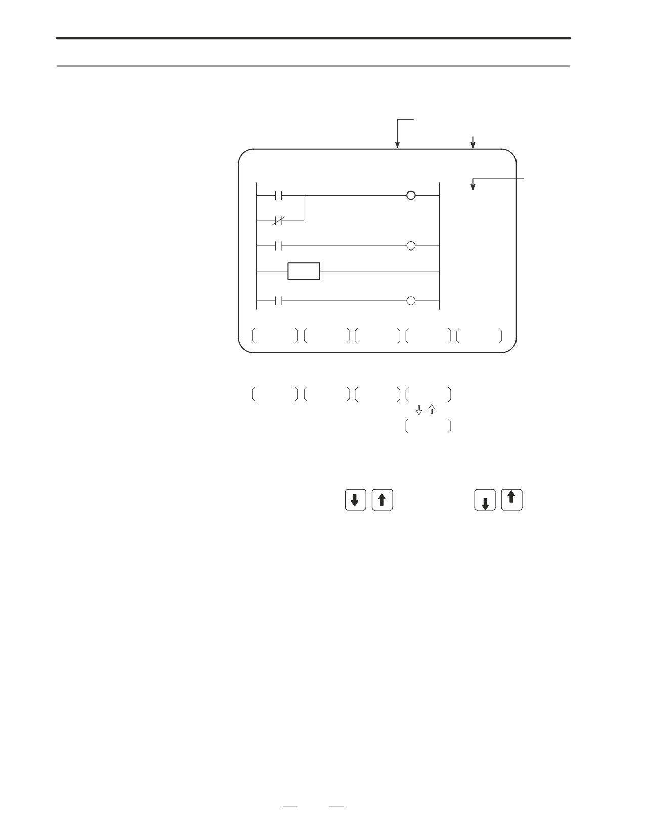
Press soft key
[PMCLAD], and a sequence program is displayed
dynamically and operation monitoring can be confirmed :
PMCLAD Screen
Number of net displayed
RUN/STOP status
Ladder display
LADDER
NET 0001-0004
MONIT RUN
Comment
LOG1
LOG1
ALWAYS1
LOG1
X008.4
*ESP
EMERGENCY
STOP
END1
PORD
POR
POWER ON
RESET
TOP
BOTTOM
SRCH
W-SRCH
N-SRCH
Other soft keys
F-SCRH
ADRESS
Switched each
time pressed
SYMBOL
D Contents displayed
1.
1Green (Low brightness) displayContacts :open Relay :off
2.
White (High brightness) display Contacts : closed Relay : on
D Search method
1.
Use the cursor keys
or the page keys PAGE
to change
PAGE
display positions.
2.
[TOP]:Searches top of ladder.
3.
[BOTTOM]:Search bottom of ladder.
4.
Address.bit,[SRCH] or Signal name, [SRCH]
5.
Address.bit,[W-SRCH] or Signal name ,[W-SRCH]
6.
Net no.[N-SRCH]:Ladder is displayed from the specified net.
7.
Functional instruction no.
[F-SRCH] or Functional instruction
name[F-SRCH]
8.
[ADRESS]:Signal is displayed by address and bit no.
9.
[SYMBOL]:Signal is displayed by signal name (symbol).
(If symbol is not registered at program preparation time, the address
of the signal is displayed).
246

B-63005EN/01
4.INTERFACE BETWEEN NC AND PMC
[Remarks]
⋅
The search function searches a signal in the forward direction and
displays the ladder with the searched signal at its head. Because there
may exist plural contacts, repeat the search operation to find plural
locations, repeat the search operation to find plural locations with the
specified signal.
⋅
If a specified signal is not found up to the end of the program (ladder),
execution returns to the head of a program and search continues.
D Dump display on ladder
Ladder diagram and signal status dump can displayed together.
diagram
The dump is displayed over 2 lines at the last line of ladder diagram by
pressing the [DUMP] soft key.
PAGE
keys or [SEARCH] soft key is used for changing of PMC
PAGE
address.
The [DUMP] soft key has the follwing functions.
(1) [BYTE]: Byte type display (1 BYTE)
“G0000 00 14 00 00 01 00 00 00 00 00 00 00 00 00 00 00”
“G0016 00 00 00 00 00 00 00 00 00 00 00 00 00 00 00 00”
(2) [WORD] : Word type display (2 BYTE)
“G0000 1400 0000 0001 0000 0000 0000 0000 0000”
“G0016 0000 0000 0000 0000 0000 0000 0000 0000”
(3) [D.WORD]: Long word type display (4 BYTE)
“G0000 00001400 00000001 00000000 00000000”
“G0016 00000000 00000000 00000000 00000000”
D Parameter display on
The value of parameter of a functional instruction is displayed in the
ladder diagram
functional instruction of a ladder diagram.
The function of the soft key is as follows:
(1) [DPARA]
: The value of parameter is displayed in functional
instruction.
(2) [NDPARA]
: The value of parameter is not displayed in functional
instruction.
D Stop of ladder diagram
The ladder display can be stopped by manual operation or trigger of
display by trigger of
signal.
signal
The former ladder diagram display renews signal status every moment.
But by using this function, all the ladder diagram at the specified moment
can be checked.
The stop conditions as a trigger are specified by rising or falling edge
detection of the designated signal.
247
4. INTERFACE BETWEEN NC AND PMC
B-63005EN/01
D Display of setting trigger
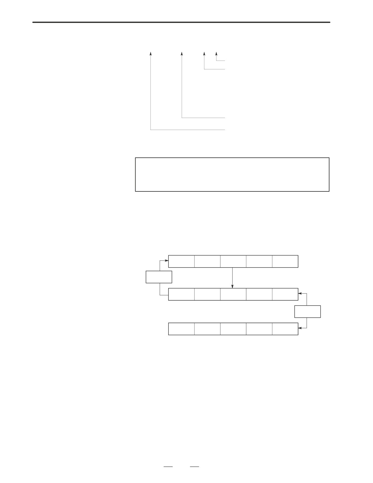
The setting address, condition and counter are displayed at the title line.
“MODE:ON : X0000. 0 : 0 : 0001 ”
COUNT: Trigger checking number (default 1)
POINT: Trigger checking number (default 0)
0 : the top of the 1st level
1 : after END1 execution
2 : after END2 execution
3 : after END3 execution
ADR: Trigger setting address
ON: Rising edge detection (TRGON)
OFF: Falling edge detection (TRGOFF)
* Setting form adr ;p1 ;p2+[TRGON/TRGOFF]soft key
NOTE
“;”=”EOB” adr (trigger address) ;p1 (trigger point) ;p2 (trigger
checking number (1~65535))
* Because parameters are stored in the nonvolatile memory, they are not
lost even if the power is turned off.
When bit 2 of keep relay K18 is set to 1 after parameters for sampling
are specified, the trigger function automatically starts when the power
is turned on.
For this operation, depress [TRIGER] soft key to bring the following
menu.
SEARCH
ADRESS
TRIGER
WINDOW
RET
TRGON
TRGOFF
START
NEXT
DUMP
DPARA
TRGSRC
INIT
The function of the [TRIGER] soft key is explained below:
(1) [TRGON] : The trigger function is stopped when a specified address
signal goes high (is turned ON).
(2) [TRGOFF] : The trigger function is stopped when a specified address
signal goes low (is turned OFF).
(3) [START]
: Pressing this key switches between trigger function
execution and trigger function termination. While the
trigger function is being executed, the ”TRG” indication
blinks.
(4) [TRGSRC]: An instruction at which the trigger function has been
stopped by a specified address signal is searched for and
indicated by blinking.
(5) [INIT]
: The trigger setting is initialized.
248

B-63005EN/01
4.INTERFACE BETWEEN NC AND PMC
D Divided display of ladder
This function is used for displaying the divided screen. It can display
diagram
max. six division.
For this operation, depress [WINDOW] soft key to bring the following
menu.
SEARCH
ADRESS
TRIGER
WINDOW
RET
DIVIDE
CANCEL
DELETE
SELECT
WIDTH
The function of the soft key [WINDOW] is as follows:
(1) [DIVIDE]
: The screen will be divided.
The dividing display of ladder diagram can be
displayed for the designated NET number.
(NET number+[DIVIDE])
(2) [CANCEL]
: The dividing display of ladder diagram display ends.
(The screen returns to normal display.)
(3) [DELETE]
: The screen division subject to operation is ended.
(4) [SELECT]
: Change the screen subject to division operation.
The screen in operation is displayed by ”purple” title
line, another screen is displayed by “blue” title line.
In monochrome CRT, the screen is displayed by
changing brightness.
(5) [WIDTH]
: Change the width of division by using [EXPAND] or
[SHRINK] soft key.
(6) [EXPAND]
: The divided screen is expanded.
(7) [SHRINK]
: The divided screen is shrank.
D ON-LINE EDIT
When bit 1 in the keep relay K17 is 1, this function is available and
[ONLEDT] soft key is displayed.
When the ladder program is executing, a part of the ladder program can
be changed.
S Change the type of contact (A contact, B contact)
S Change address of contact and coil.
S Change address parameter of functional instruction.
This function don’t change the size.
(Cannot be Addition, deletion and chanegable data size)
When bit 3 in the keep relay K18 is 1, this program is automatically
transferred to backup RAM after on-line edit.
When bit 3 in the keep relay K18 is 0, transfer to backup RAM with COPY
function of I/O screen. If power is off without this operation, edited data
is lost.
249
4. INTERFACE BETWEEN NC AND PMC
B-63005EN/01
4.3.3
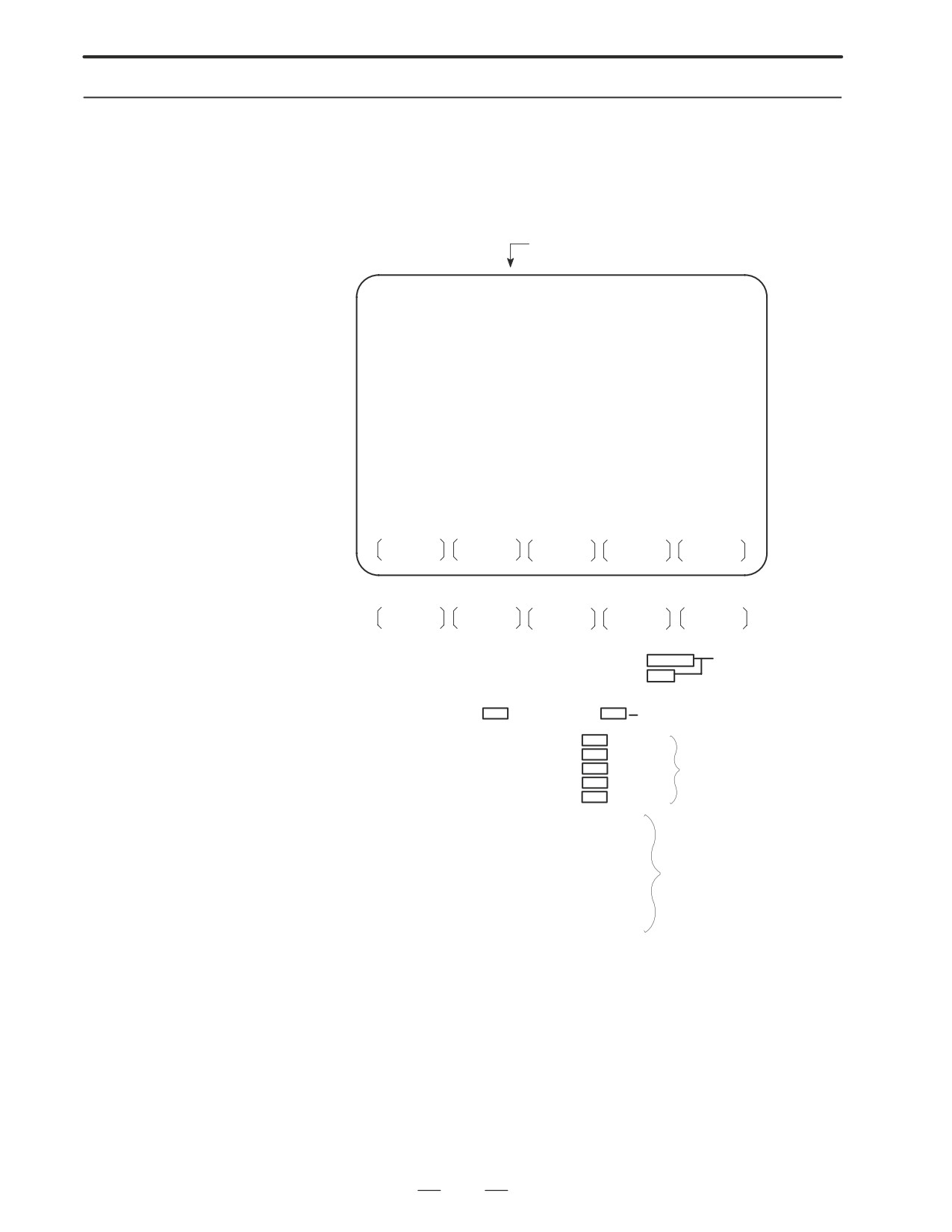
Press soft key [PMCDGN] then PMC’s diagnostic screen is displayed.
PMCDGN Screen
D TITLE screen
The title data registered when a ladder program is prepared is displayed.
Page number
PMC TITLE DATA #1
MONIT RUN
PMC PROGRAM NO.
:
EDITION NO.
:
PMC CONTROL PROGRAM
SERIES : 4063 EDITION : 08
(SERIES : 4065 EDITION : 08)
PMC TYPE CONTROL : RB3 PROGRAM : RB3
MEMORY USED
:
KB
LADDER
:
KB
SYMBOL
:
KB
MESSAGE
:
KB
SCAN TIME
:
MSEC
SCAN MAX : 016 MS MIN : 008 MS
TITLE
STATUS
ALARM
TRACE
Other soft keys
M.SRCH
ANALYS
1st page PMC PROGRAM NO.
:
ÄÄÄ Set when PMC
EDITION NO.
:
is
ÄÄÄ
prepared
PMC COÄÄROGRAM
ÄÄ
SERIES :
EDITION :
Series and edition of PMC
ÄÄ
ÄÄÄ
control software
MEMORY USED
:
KB
LADDER
:
ÄÄ
KB
Memory used and
SYMBOL
KB
execution time is
MESSAGE
:
ÄÄKB
displayed.
SCAN TIME
MSEC
ÄÄ
2nd page MACHINE TOOL BUILDER NAME :
MACHINE TOOL NAME :
CNC & PMC TYPE NAME :
PROGRAM DRAWING NO. :
Set when PMC
is prepared.
3rd page DATE OF DRAWING :
PROGRAM DESIGNED BY :
ROM WRITTEN BY :
REMARKS :
250
B-63005EN/01
4.INTERFACE BETWEEN NC AND PMC
D STATUS screen
On/Off state of input/output signals and internal relay is displayed.
PMC SIGNAL STATUS
MONIT RUN
ADDRESS
7
6
5
4
3
2
1
0
ED7 ED6 ED5 ED4 ED3 ED2 ED1 ED0
Signal
G0000
0
0
0
0
1
0
1
0
name
ED15 ED14 ED13 ED12 ED11 ED10 ED9 ED8
Signal state
0:Off
G0001
0
0
0
0
0
0
0
0
1:On
ESTB EA6 EA5 EA4 EA3 EA2 EA1 EA0
G0002
0
0
0
0
0
0
0
0
Signal state
G0003
0
0
0
0
0
0
0
0
reverses for
FIN
signals with *.
G0004
0
0
0
0
0
0
0
0
0: On
1: Off
SEARCH
[Search Method]
• Page key :Forward and Backward by screen
• Cursor key :Forward and Backward by diagnostic number
• To search a specified address or signal name, input an address number
or signal name and press [SEARCH].
D Alarm screen
Displays an alarm generated in PMC.
PMC ALARM MESSAGE
MONIT RUN
Alarm dis-
play
ER32 NO I/O DEVICE
For details
of alarms,
refer to
Appendix
2 List of
Alarms.
ALM
Blinked
TITLE
STATUS
ALARM
TRACE
251
4. INTERFACE BETWEEN NC AND PMC
B-63005EN/01
D TRACE screen
Every time a specified signal changes, the signal status is memorized in
the trace memory. This function is useful for identifying intermittent
troubles.
1
Trace parameter screen
PMC SIGNAL TRACE
MONIT RUN
TRACE MODE
:
(0:1BYTE/1:2BYTE/2:WORD)
1STTRACE ADDRESS CONDITION
ADDRESS TYPE
: (0:PMC/1:PHY)
ADDRESS
:
MASK DATA
:
2NDTRACE ADDRESS CONDITION
ADDRESS TYPE
: (0:PMC/1:PHY)
ADDRESS
:
MASK DATA
:
T.DISP
EXEC
Changes to a trace memory display screen (Screen on
the next page)
Select each item by cursor key
a.
TRACE MODE: Select the trace mode
0=Records changes of 1-byte signals
1=Records changes of independent 2-byte signals
2=Records changes of consecutive 2-byte signals
b.
ADDRESS TYPE:
0=PMC address is used for tracing address.
1=Physical address is used for tracing address.
(Mainly used for C-language program)
c.
ADDRESS:Set a tracing address.
d.
MASK DATA: The bits to be traced are specified by a hexadecimal
number (2 digits).
For example, to trace the signals at bit
7,6,5 and
0, set E1
(hexadecimal) to MASK DATA.
#7 #6 #5 #4 #3 #2 #1 #0
E1%
1
1
1
0
0
0
0
1
However, even if bit
4,3,2 and
1 changes, tracing
(memory
registration) cannot be done but signal status is memorized when a
tracing is executed.
[Correspondence of binary and hexadecimal number]
00002 : 016
00012 : 116
00102 : 216
00112 : 316
01002 : 416
01012 : 516
01102 : 616
01112 : 716
10002 : 816
10012 : 916
10102 : A16
10112 : B16
11002 : C16
11012 : D16
11102 : E16
11112 : F16
252
B-63005EN/01
4.INTERFACE BETWEEN NC AND PMC
2
Trace memory contents display screen
PMC SIGNAL TRACE
MONIT RUN
1ST ADDRESS=X008(E1)
2ND ADDRESS=G000(FF)
Trace
address
NO.
76543210
76543210
and mask
data(in pa-
0000
rentheses)
0001
I * * * * * * *
* * * * * * * *
0002
I I * * * * * *
* * * * * * * *
0003À*ÀI****À**ÀÀÀ*À**À**À***À
Latest status
0004
I mark : 1
* mark : 0
0005
0006
0007
0008
TRCPRM
STOP
10″LCD/14″CRT is dis-
played by 1 and 0.
a. Soft key [TRCPRM]:Return to the trace parameter setting screen
(screen of previous page)
b. Soft key [EXEC]:
Starts tracing.
Trace memory is cleared and each time a
specified signal changes, its status is recorded.
Trace memory is 256 bytes and if tracing is
executed 128 times by 2-byte tracing, tracing
is executed again from the head of memory.
c. Soft key [STOP]:
Ends the tracing.
*The tracing parameters are held even if the power is turned off.
#7
#6
#5
#4
#3
#2
#1
#0
K017
ÀÀÀÀ
#5
0 : Tracing starts by [EXEC].
1 : Tracing starts automatically after power on
253
4. INTERFACE BETWEEN NC AND PMC
B-63005EN/01
4.3.4
Memory Display
(M.SRCH)
D Display of Screen and
Operation
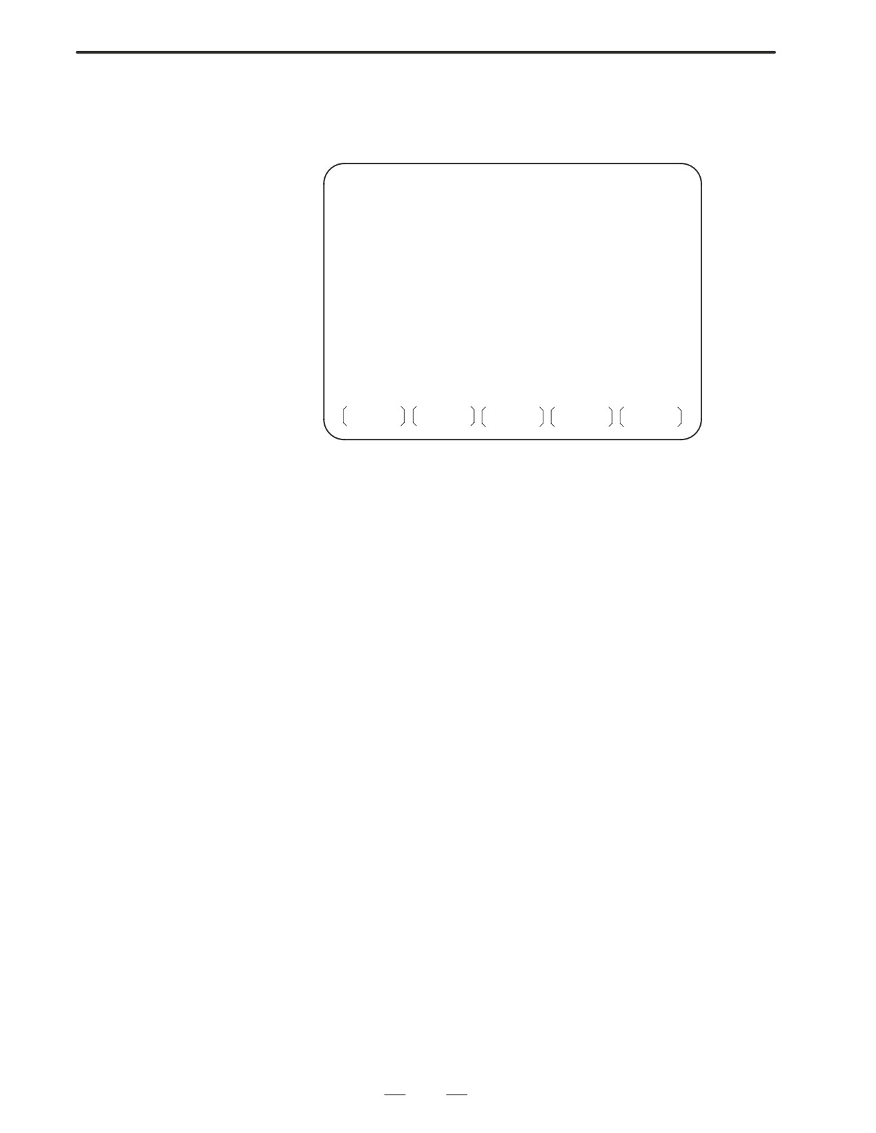
1) Pressing the [M.SRCH] soft key changes the screen to that shown in
Fig. 3.5. The displayed soft keys also change.
2) Enter a physical address in hexadecimal from which the contents of the
memory are to be displayed. Then pressing the [SEARCH] key
displays 256 byte of stored data starting from the specified address.
Example) Enter 100000, then pressing the [SEARCH] keydisplays
the contents of the memory starting from 100000H.
3) An address can be changed using the PAGE
or
key.
PAGE
4) Pressing either the
[BYTE], [WORD], or [D.WORD] soft key
displays data of the corresponding type.
If an address at which the memory is not used is specified, a system
error occurs.
D Function of store
To store data in memory, set bit 4 of keep relay K17 to 1, move the cursor
memory
to a position at which the address of the data to be changed in RAM is
displayed, and enter data in units of data type in hexadecimal.
Example) Entering 0F41, then pressing the
INPUT
key stores
0F41 at the address specified by the cursor
PMC CONTENTS OF MEMORY
MONIT RUN
100000
0000 0000 0000 0000 0000 0000 0000 0000
100010
4142 4344 4546 4748 494A 4B4C 4D4E 4F50 ABCDEFGHIJKLMNOP
100020
2020 2020 2020 2020 2020 2020 2020 2020
100030
5152 5354 5556 5758 595A 2020 2020 2020 QRSTUVWXYZ
100040
0000 0000 0000 0000 0000 0000 0000 0000
100050
0000 0000 0000 0000 0000 0000 0000 0000
100060
0000 0000 0000 0000 0000 0000 0000 0000
100070
0000 0000 0000 0000 0000 0000 0000 0000
100080
4641 4E55 4320 434F 2E2C 5444 0000 0000 FANUC CO.LTD
100090
0000 0000 0000 0000 0000 0000 0000 0000
1000A0
0000 0000 0000 0000 0000 0000 0000 0000
1000B0
0000 0000 0000 0000 0000 0000 0000 0000
1000C0
0000 0000 0000 0000 0000 0000 0000 0000
1000D0
0000 0000 0000 0000 0000 0000 0000 0000
1000E0
0000 0000 0000 0000 0000 0000 0000 0000
1000F0
0000 0000 0000 0000 0000 0000 0000 0000
SEARCH
INPUT
254
B-63005EN/01
4.INTERFACE BETWEEN NC AND PMC
D ANALYS screen
Change of signals is displayed as the same display as that on the
(Ladder editing card is
oscilloscope.
required for PMC-RB5/
1
Parameter setting screen (1st page)
RB6)
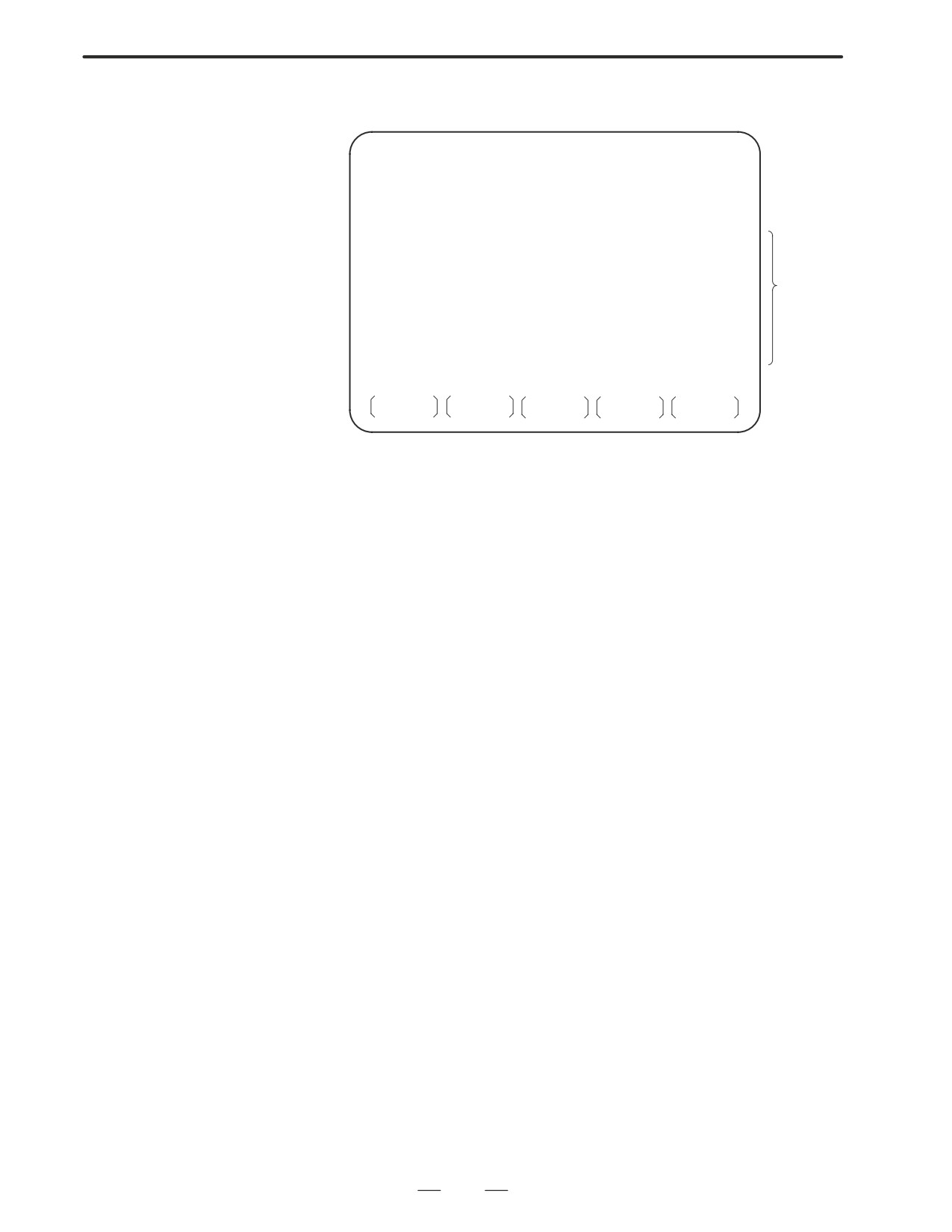
PMC SIGNAL ANALYSIS(PARAM)
MONIT RUN
SAMPLING TIME
:
10 (1-10 SEC)
(a)
TRIGGER ADDRESS
: G 0007.2
(b)
CONDITION
:
0
(c)
(0: START 1: TRIGGER-ON 2: TRIGGER-OFF)
TRIGGER MODE
:
0
(d)
(0: AFTER 1: ABOUT 2: BEFORE 3: ONLY)
SCOPE
DELETE
INIT
ADDRESS
Select each item by
cursor key
(a) Set a sampling time.
(b) Specifies an address from which recording of signals is started.
(c) Set a condition under which recording is initiated.
0 : Started by soft key [START]
1 : Started by rise of a trigger signal after you press the soft key
[START]
2 : Started by fall of a trigger signal after you press the soft key
[START]
(d) Set a trigger mode
0 : Record signal status after the trigger condition is satisfied
1 : Record signal status before and after the trigger condition is
satisfied.
2 : Record signal status before the trigger condition is satisfied.
3 : Record signal status when the trigger condition is satisfied.
(Display is same as trace memory).
255
4. INTERFACE BETWEEN NC AND PMC
B-63005EN/01
2
Parameter setting screen (2nd page)
PMC SIGNAL ANALYSIS(PARAM)
MONIT RUN
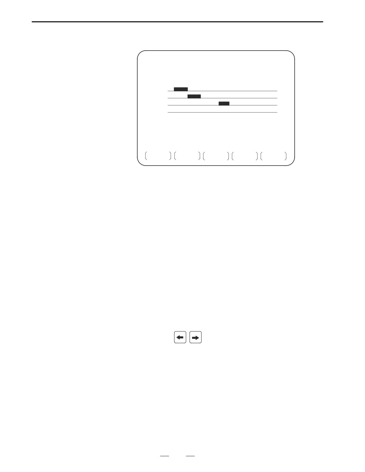
SIGNAL ADDRESS
1 : X0000.0 9 : Y0000.0
2 : X0000.1 10 : R0000.1
3 : X0002.0 11 :
Up to 16
4 : X0005.0 12 :
signals
5 :
13 :
6 :
14 :
7 :
15 :
8 :
16 :
SCOPE
DELETE
INIT
ADDRESS
a. Soft key [SCOPE]:Select signal waveform display screen
b. Soft key [DELETE] :Delete data on the cursor position
c. Soft key [INIT] :Initialize parameters of signal waveform display
d. Soft key [ADDRESS] or [SYMBOL] :Switch
addresses
and
symbols for display
256
B-63005EN/01
4.INTERFACE BETWEEN NC AND PMC
3
SCOPE screen
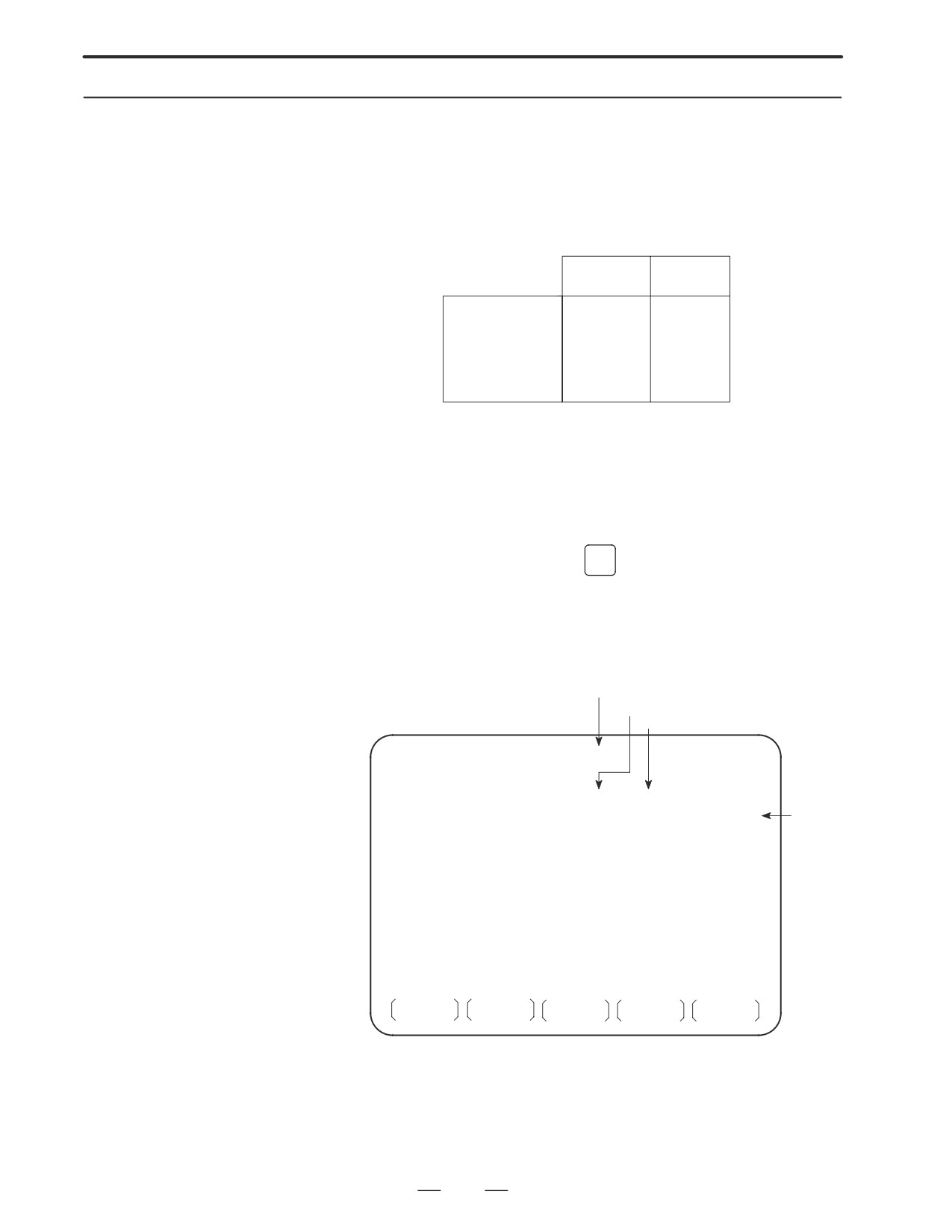
PMC SIGNAL ANALYSIS(PARAM)
MONIT RUN
SAMPLING TIME : 10 CONDITION : 1
TRIGGER ADDRESS : G0007.2 TRIGGER MODE : 0
+---------+---------+---------+------
X0000.0
X0000.1
X0002.0
X0005.0
+---------+---------+---------+------
0
256(MSEC)
SGNPRM
START
T.SRCH
ADDRESS
The above screen is for a system with graphic display.
”J” and ”-” are used for display if graphic function is not equipped.
a. Soft key [SGNPRM]
: Returns to parameter screen.
b. Soft key [START] or [STOP]
:Start or stop the record.
(If TRIGGER MODE=3, signal is displayed when you press STOP
key.)
c. Soft key [T.SRCH]
:Displayed for a specified time.
d. Soft key [ADDRESS] or [SYMBOL] :Switch
addresses
and
symbols for display
e. Soft key [EXCHG] : Change order of signals displayed.
·Press soft key [EXCHG]
·Move the cursor to a signal to be changed.
·Press soft key [SELECT].
·Move the cursor to the destination.
·Press [TO] and [EXEC], then the signal changes its order.
f. Soft key [SCALE] : Changes time scale for graphic display. Scale
changes from 256 to 512, and to 1024 msec every time you press the
key.
g. Cursor key
: Scrolls time axis forward and backward
257
4. INTERFACE BETWEEN NC AND PMC
B-63005EN/01
4.3.5
PMCPRM Screen
D Inputting PMC
parameters from the MDI
1
Set to MDI mode or emergency stop state.
2
Set PARAMETER WRITE (on setting screen) to 1 or set the program
protect signal (KEY4) to 1.
PWE
KEY4
Timer
f
-
Counter
f
f
Either one
Keep relay
f
-
Data table
f
f
Either one
3
Press a soft key and select a required screen.
[TIMER]
:Timer screen
[COUNTR] :Counter screen
[KEEPRL] :Keep relay screen
[DATA]
:Data table screen
4
Press cursor key and move the cursor to a desired number.
5
Input a numeric key and press
INPUT
key and data is input.
6
After the data is input, set PARAMETER WRITE or KEY4 on setting
screen to 0.
D TIMER screen
This screen is used for setting timer time of the functional instruction
(SUB 3).
Page no. (screen is scrolled by page key)
Timer no. specified by functional instruction
Address specified by ladder
PMC PARAMETER (TIMER) #001
MONIT RUN
NO.ADDRESS DATA
NO.ADDRESS
DATA
01
T00
480
11
T20
0
Timer
delay
02
T02
960
12
T22
0
time
03
T04
0
13
T24
0
(msec)
04
T06
0
14
T26
0
05
T08
0
15
T28
0
06
T10
0
16
T30
0
07
T12
0
17
T32
0
08
T14
0
18
T34
0
09
T16
0
19
T36
0
10
T18
0
20
T38
0
TIMER
COUNTR
KEEPRL
DATA
Timer set time : Timer no. 1-8 is max. 1572.8 sec and its accuracy is
48ms.
Timer no. 9 is max. 262.1 sec and its accuracy is 8ms.
258
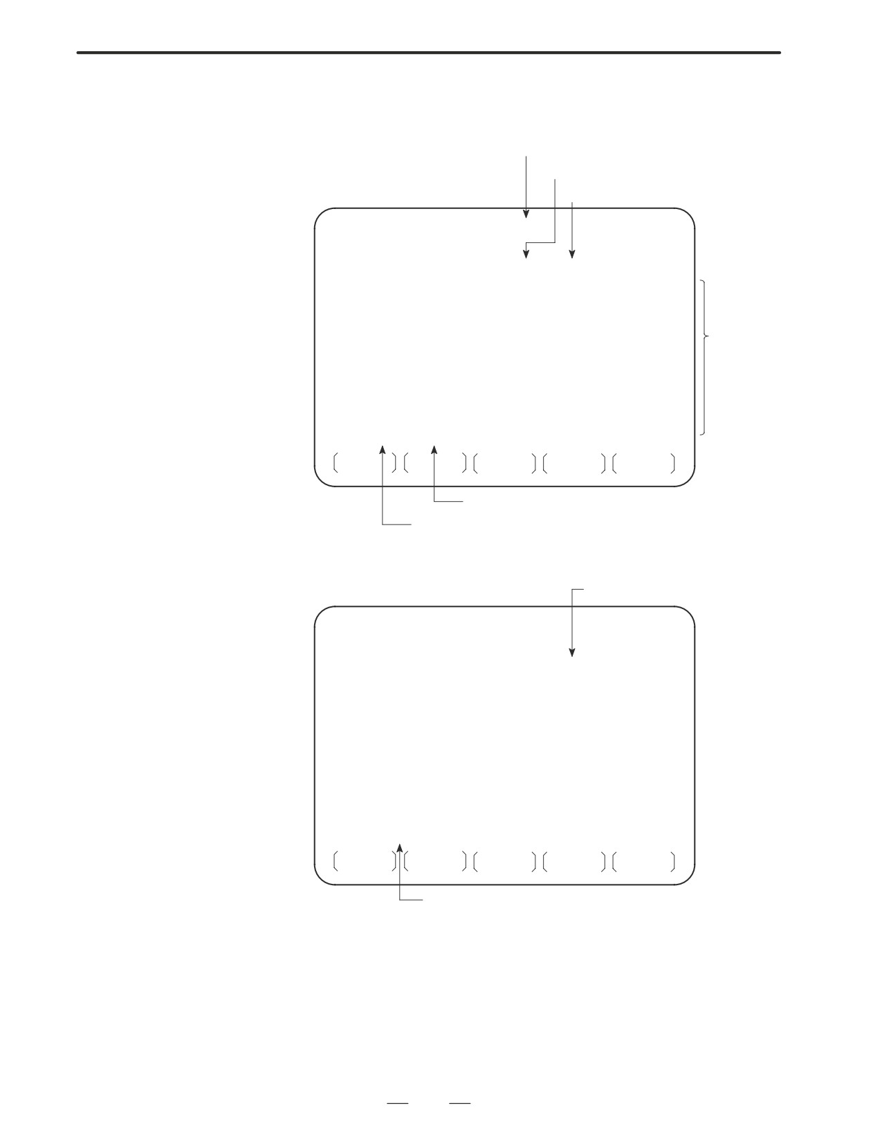
B-63005EN/01
4.INTERFACE BETWEEN NC AND PMC
D COUNTER screen
This screen sets and displays max. value of counter and current value of
the counter instruction (SUB 4).
Page no. (screen is scrolled by page key)
Max. value of counter (Minimum
value is specified by counter ins.)
Current value of counter
PMC PARAMETER (COUNTER)#001
MONIT RUN
NO. ADDRESS
PRESET CURRENT
01
C00
100
1
PRESET
02
C04
50
2
and CUR-
03
C08
0
0
RENT
can be set
04
C12
0
0
up to
05
C16
0
0
9999, re-
spectively.
06
C20
0
0
07
C24
0
0
08
C28
0
0
09
C32
0
0
10
C36
0
0
TIMER
COUNTR
KEEPRL
DATA
Address specified by ladder
Counter number specified by func-
tional instruction
D KEEP RELAY screen
Address specified by ladder
PMC PARAMETER (KEEP REALAY) #001
MONIT RUN
NO.ADDRESS
DATA
NO.ADDRESS
DATA
01 K00
00000000
11 K10
00000000
02 K01
00000000
12 K11
00000000
03 K02
00000000
13 K12
00000000
04 K03
00000000
14 K13
00000000
05 K04
00000000
15 K14
00000000
06 K05
00000000
16 K15
00000000
07 K06
00000000
17 K16
À00000000
08 K07
00000000
18 K17
À00000000
09 K08
00000000
19 K18
00000000
10 K09
00000000
20 K19
ÀÀÀÀ
00000000
ÀÀÀÀ
TIMER
COUNTR
KEEPRL
DATA
Address specified by ladder
ÀÀUsed by PMC system
ÀÀ
259