FANUC Series 16i / 18i / 160i / 180i - Model A. Maintenance Manual (B-63005EN/01) - page 7
2. HARDWARE
B-63005EN/01
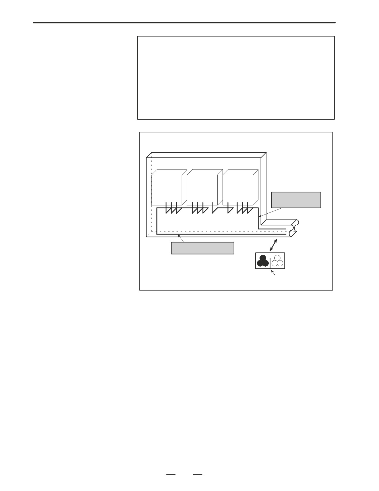
NOTE
1
Separate binding is to separate the bound cables of one
group at least 10 cm from the bound cables of another
group.
2
Electromagnetic shielding is to shield the bound cables of
one group from the bound cables of another group with a
grounded metal (iron) plate.
3
If the CNC-MDI cable is not longer than 30 cm, shielding is
not required.
Cabinet
Spindle
Servo
Control
amplifier
amplifier
unit
Cables of groups
B and C
Duct
To opera-
tor’s panel,
motor, or
other units
Cross section
Cables of group A
Group A
Groups B and C
Shielding plate
170
2. HARDWARE
B-63005EN/01
2.15.2
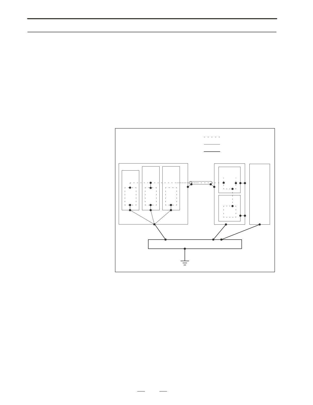
With a CNC machine tool, three ground systems are used.
Grounding
(1) Signal ground system (SG)
Signal ground (SG) provides a reference voltage (0 V) for the electric
signal system.
(2) Frame ground system (FG)
The purposes of frame ground (FG) are to ensure safety and to provide
shielding from external and internal noises. Specifically, the frames
of equipment, unit cases, panels, inter-unit interface cables, and so
forth are shielded.
(3) System ground system
The system ground system is designed to connect the frame ground
system (FG) provided between equipment and units to ground.
Signal ground system
Frame ground system
System ground system
Machine
Power
Servo am-
CNC con-
24 VDC
magnetics
plifier
trol unit
power
unit
supply
Distribution board
Notes on ground system
wiring
D Connect system ground (0 V) to frame ground (FG) at only one point
of the CNC control unit.
D The ground resistance of system ground must not exceed 100 ohms
(class-3 grounding).
D A cable for system grounding must have a cross sectional area
sufficient for flowing accidental currents that can flow to system
ground in case of an accident such as a short-circuit.
(In general, a
cable for system grounding must have a cross sectional area equal to
or greater than that of an AC power cable.)
D As a cable for system grounding, use a cable integrated with an AC
power cable so that power is not supplied when the ground wire is
disconnected.
171
2. HARDWARE
B-63005EN/01
2.15.3
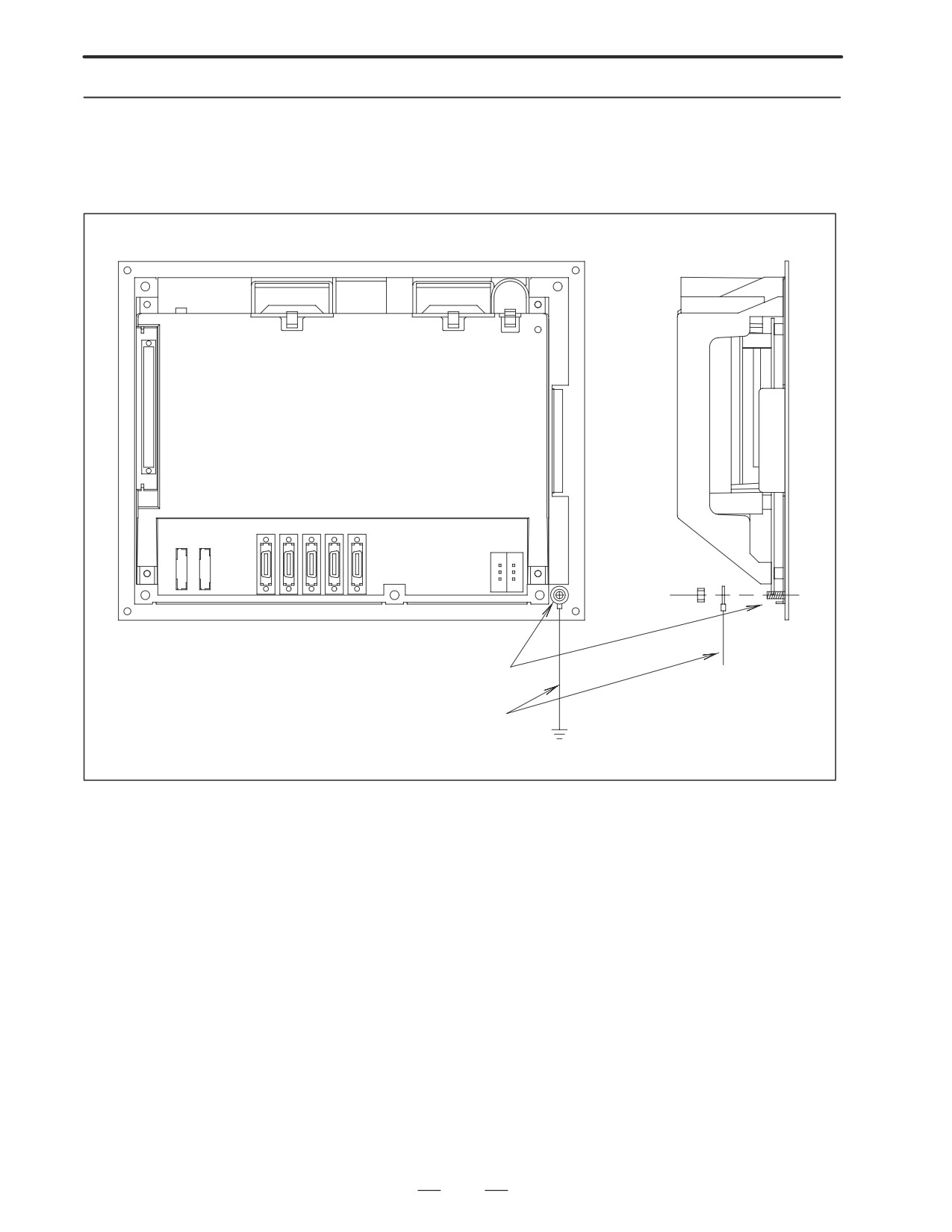
Signal Ground (SG)
Connection of Control
Unit
M4 stud
Ground cable
Wire of 2 mm2 or more
Connect the 0 V line inside the control unit to the ground plate of the
cabinet through the signal ground (SG) terminal (shown above).
172
2. HARDWARE
B-63005EN/01
2.15.4
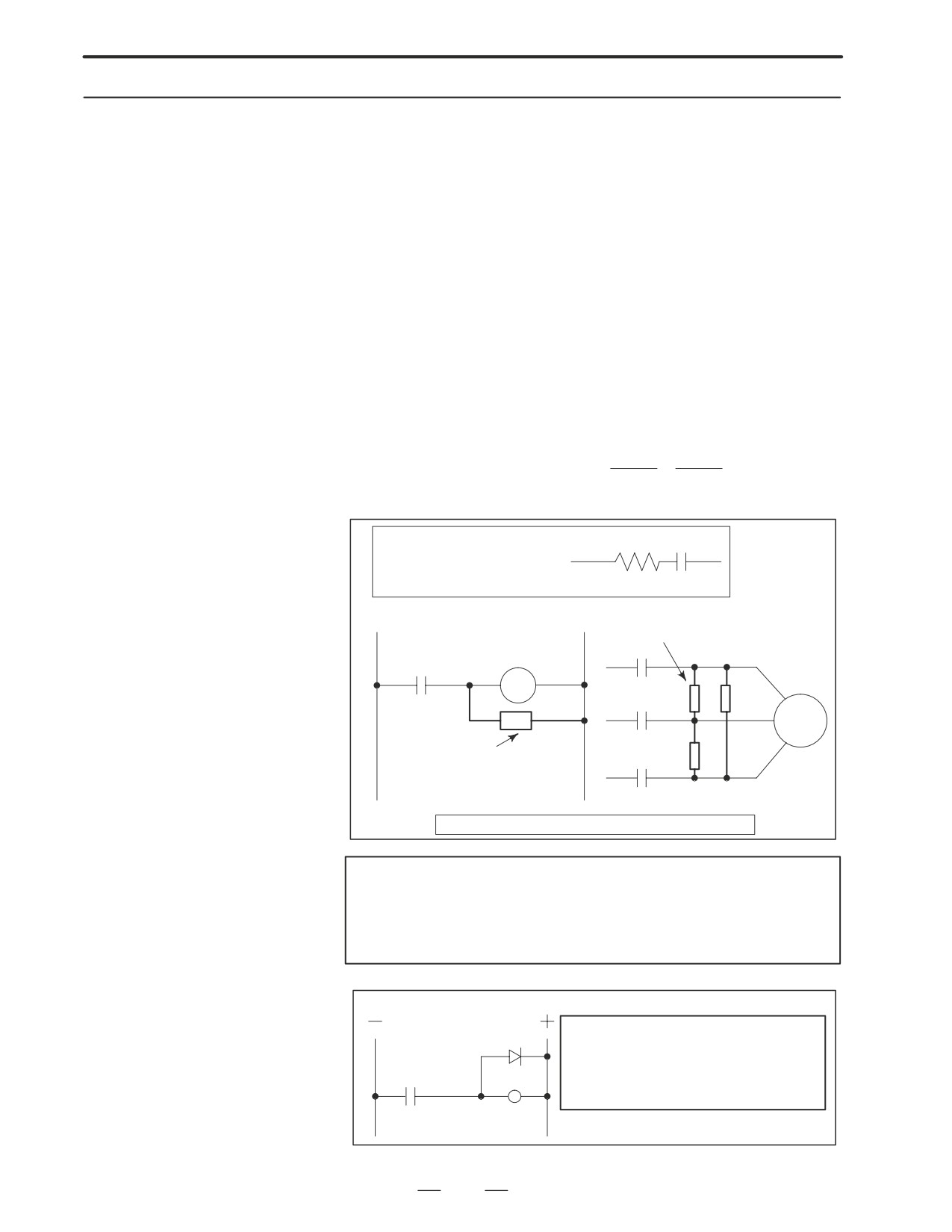
With a power magnetics cabinet, components such as an AC/DC solenoid
and AC/DC relay are used. When turned on and off, these components
Noise Suppressor
generate a high-energy pulse voltage due to coil inductance.
Such a pulse voltage is induced into cables, for example, and can interfere
with electric circuitry.
Notes on spark killer
selection
D Select a CR-type spark killer (for use with AC circuitry) (A varistor
has a function for clamping the peak voltage of a pulse voltage, but
cannot suppress a spike-like voltage. For this reason, the use of a
CR-type spark killer is recommended.)
D As the CR values of a spark killer, use the following with the
steady-state coil current (I (A)) and DC resistance used as references:
1) Resistance (R): Coil DC resistance
2
2
I
I
2) Electrostatic capacitance (C):
to
(mF)
10
20
I: Coil steady-state current (A)
R
C
Equivalent circuit of spark killer
Spark killer
AC relay
Motor
Spark killer
Install a spark killer near a motor, relay, and coil.
NOTE
Use a CR-type noise suppressor. A varistor has a function
for clamping the peak voltage of a pulse voltage, but cannot
suppress a spike-like voltage.
Diode (used for DC circuitry)
As a guideline, select a diode which has
Diode
a breakdown voltage about two times
greater than an applied voltage, and al-
DC relay
lows the flow of a current about two
times higher.
173
2. HARDWARE
B-63005EN/01
2.15.5
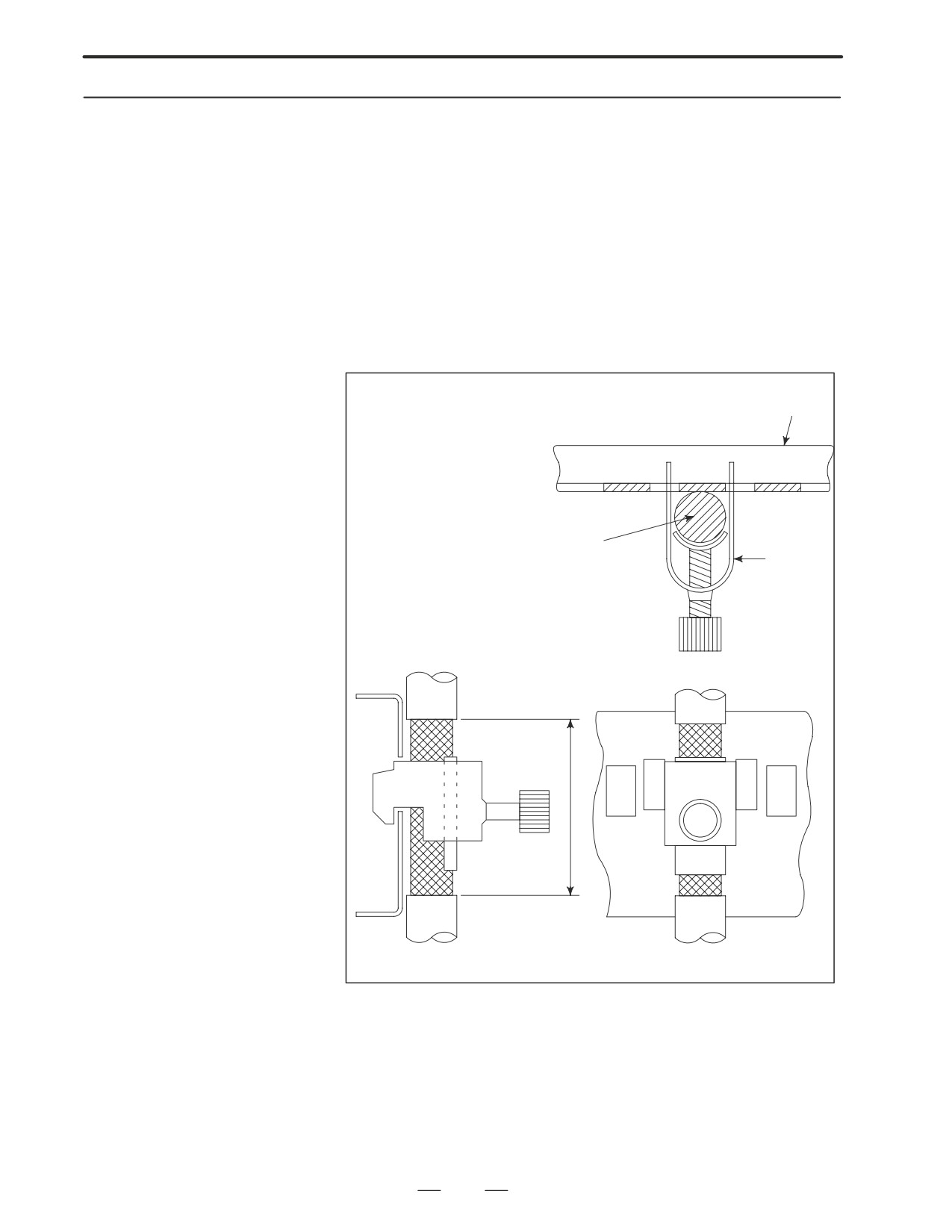
According to the figure below, clamp all cables that require shielding and
are run to the CNC, servo amplifier, spindle amplifier, and so forth. This
Cable Clamping and
clamping method not only secures cables, but also shields cables. Cable
Shielding
clamping and shielding are a key to stable system operation. Always
perform cable clamping and shielding according to the method described
here.
As shown below, peel off a part of the outer sheath of each cable so that
the shield cover is exposed, then press and retain the exposed part of the
shield against the ground plate with a clamp.
Install a ground plate manufactured by the machine tool builder, as shown
below.
Ground plate
Cable
Clamp
40mm∼80mm
Fig. 2.15.5(a) Cable clamp (1)
174
2. HARDWARE
B-63005EN/01
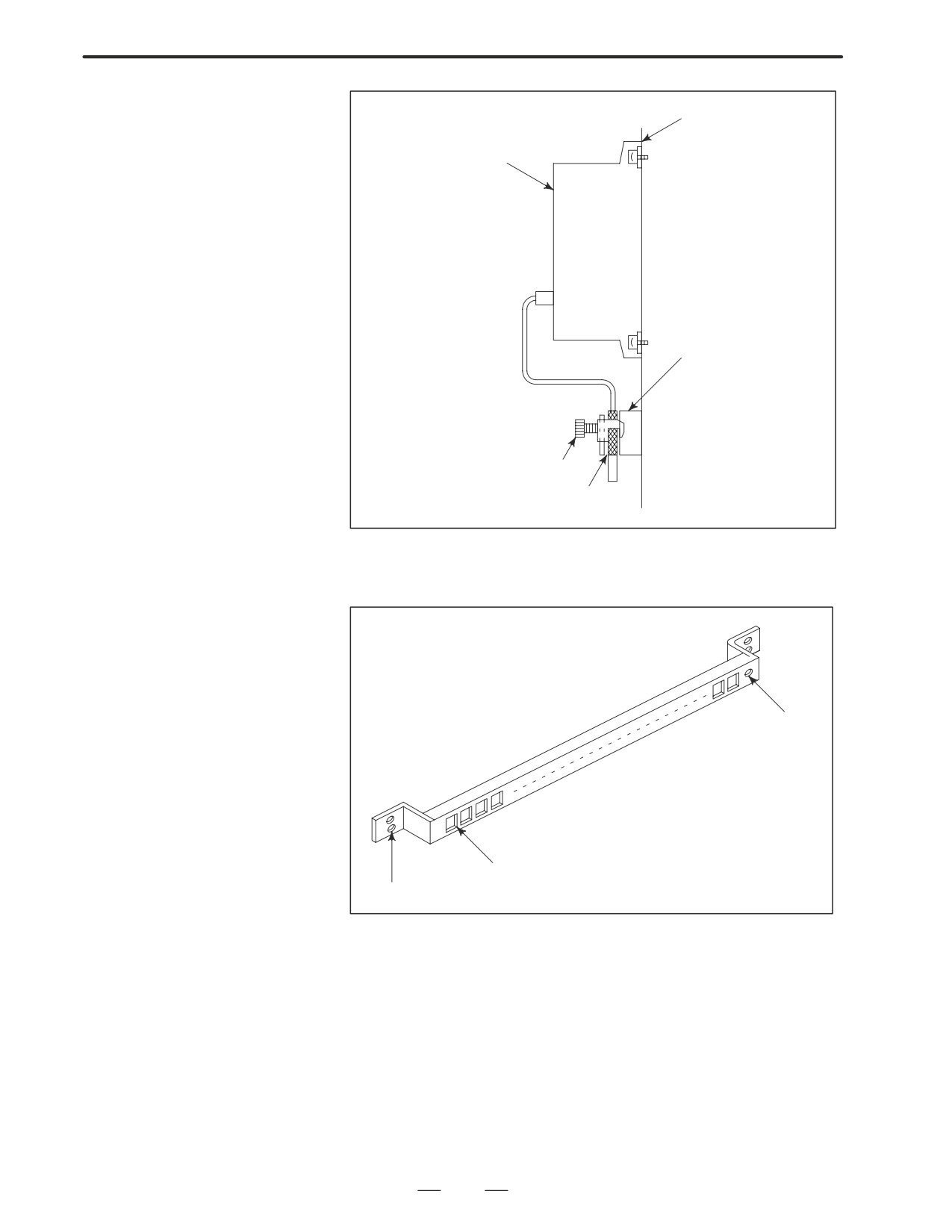
Mounting plate of the machine
ÇÇ
ÇÇ
Control unit
ÇÇ
ÇÇ
ÇÇ
ÇÇ
ÇÇ
ÇÇ
ÇÇ
ÇÇ
Ground plate
ÇÇ
ÇÇ
ÇÇ
ÇÇ
Clamp
ÇÇ
Shield cover
ÇÇ
ÇÇ
Fig. 2.15.5(b) Cable clamp (2)
Prepare a ground plate as shown below.
Ground terminal
(to be connected
to ground)
Clamp mounting hole
Mounting hole
Fig. 2.15.5(c) Ground plate
For a ground plate, use an iron plate that is as thick as 2 mm or more and
is plated with nickel.
175
2. HARDWARE
B-63005EN/01
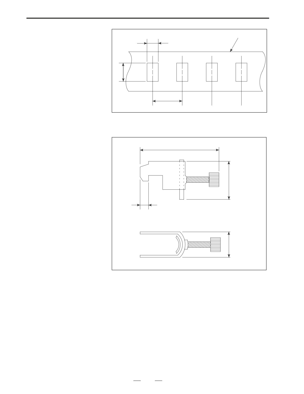
Ground plate
8mm
12mm
20mm
Fig. 2.15.5(d) Ground plate hole diagram
Reference: Outline drawing of the clamp
55 mm maximum
28mm
6mm
17mm
Fig. 2.15.5(e) Outline drawing of clamp
Ordering code of the clamp: A02B-0124-K001 (set of 8 clamps)
176
3. INPUT AND OUTPUT OF DATA
B-63005EN/01
INPUT AND OUTPUT OF DATA
3
After you change a SRAM module, you must set various data again.
This chapter describes the procedures to input and output the parameters,
the part programs and the tool offset values.
3.1
SETTING PARAMETERS FOR
INPUT/OUTPUT
178
3.2
INPUTTING/OUTPUTTING DATA
180
3.3
INPUT/OUTPUT SUPER CAP DATA
189
3.4
INPUTTING/OUTPUTTING CAP-II DATA
(16i-T)
201
3.5
DUMP / RESTORE OF CAP-II DATE (16i-T)
203
3.6
CLEARING CAP-II DATE (16i-T)
204
3.7
DATA INPUT/OUTPUT ON THE
ALL IO SCREEN
206
3.8
DATA INPUT/OUTPUT USING
A MEMORY CARD
227
177
3. INPUT AND OUTPUT OF DATA
B-63005EN/01
3.1
SETTING
PARAMETERS
FOR INPUT/OUTPUT
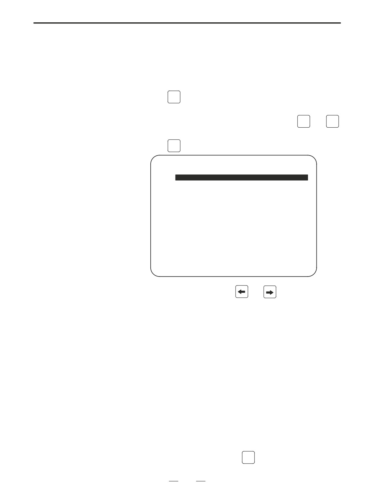
D Setting procedure of
1.
Set to MDI mode or emergency stop state.
parameters
OFFSET
2.
Press
SETTING
key several times or press soft key [SETING] to display
SETTING (HANDY) screen.
3.
Set the cursor to PARAMETER WRITE and, press
1
and
INPUT
keys in this order. Here alarm 100 will be displayed.
4.
Press
SYSTEM
key several times to display the following screen.
PARAMETER (SETTING)
O1234N12345
0000
SEQ
INI ISO TVC
0
0
0
0
0
0
0
0
0001
FCV
0
0
0
0
0
0
0
0
0012
RMV
MIR
X
0
0
0
0
0
0
0
0
Y
0
0
0
0
0
0
0
0
Z
0
0
0
0
0
0
0
0
B
0
0
0
0
0
0
0
0
0020 I/O CHANNEL
S
0 T0000
REF **** *** ***
10:15:30
[ F SRH ][ READ
][ PUNCH ][DELETE ][
]
To make the cursor display in bit unit,
press the cursor key
or
5.
Press soft key[(OPRT)] and the following operation menu
is
displayed.
1) Soft key [NO. SRH] : Searched by number.
Examination) Parameter number → [NO. SRH].
2) Soft key [ON : 1] :
Item with cursor position is set to 1
(bit parameter)
3) Soft key [OFF : 0] : Item with cursor position is set to 0
(bit parameter)
4) Soft key [+INPUT] : Input value is added to the value at cursor
(word type)
5) Soft key [INPUT] : Input value is replaced with the value at
cursor (word type)
6) Soft key [READ] : Parameters are input from reader/puncher
interface.
7) Soft key [PUNCH] : Parameters are output to reader/puncher
interface.
6.
After the parameters have been input, set PARAMETER WRITE on
the SETTING screen to 0. Press
RESET
to release alram 100.
178
3. INPUT AND OUTPUT OF DATA
B-63005EN/01
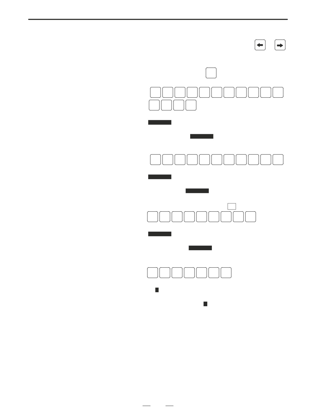
7.
Convenient method
1)
To change parameters in bit unit, press cursor key
or
,
then the cursor becomes bit length and you can set parameters bit
by bit (Bit parameter only).
2)
To set data consecutively, use
EOB
key.
(Ex.1)
1
2
3
4
EOB
4
5
6
7
EOB
9
9
9
9
INPUT
This key sequence sets data as follows:
0
1234
0
⇒
4567
0
9999
0
0
(Ex.2)
1
2
3
4
EOB
EOB
9
9
9
9
INPUT
This key sequence sets data as follows:
0
1234
0
⇒
0
0
9999
0
0
3)
To set the same data sequentially, press
=
(Ex.)
1
2
3
4
EOB
a
EOB
a
INPUT
This key sequence sets data as follows:
0
1234
0
⇒
1234
0
1234
0
0
4)
Bit parameters can be set as follows:
(Ex.)
1
1
EOB
a
EOB
a
INPUT
This key sequence sets data as follows:
0 0 0 0 0 0 0 0
0 0 0 1 1 0 0 0
0 0 0 0 0 0 0 0
⇒ 0 0 0 1 1 0 0 0
0 0 0 0 0 0 0 0
0 0 0 11 0 0 0
0 0 0 0 0 0 0 0
0 0 0 0 0 0 0 0
8.
After the required parameters are set, set PARAMETER WRITE to
0.
179

3. INPUT AND OUTPUT OF DATA
B-63005EN/01
The main CPU memorized the following data.
3.2
Outputting the data 1/O device while the CNC is rurnning normally
INPUTTING/
(1) CNC paramter
OUTPUTTING
(2) PMC parameter
DATA
(3) Pitch error compensation amount
(4) Custom macro variable values
(5) Tool compensation amount
(6) Part program (machining program, custom macro program)
Be sure that data output cannot be done in an alarm status.
3.2.1
Parameters required for output are as follows :
Confirming the
Parameters Required for
Data Output
#7
#6
#5
#4
#3
#2
#1
#0
0000
ISO
#1 (ISO)
0 :
Output with EIA code
1 :
Output with ISO code (FANUC cassette)
0020
Selection of I/O channel
0 :
Channel 1 (JD36A of mother board)
1 :
Channel 1 (JD36A of mother board)
2 :
Channel 2 (JD36B of mother board)
3 :
Channel 3 (JD38A of serial communication board)
#7
#6
#5
#4
#3
#2
#1
#0
0101
NFD
ASI
SB2
#7 (NFD)
0 :
Feed is output when data is output.
1 :
Feed is not output when data is output.
#3 (ASI)l
0 :
EIA or ISO code is used for input/output data.
1 :
ASCII code is used.
#0 (SB2)
0 :
No. of stop bits is 1.
l 1 : No. of stop bits is 2.
180
3. INPUT AND OUTPUT OF DATA
B-63005EN/01
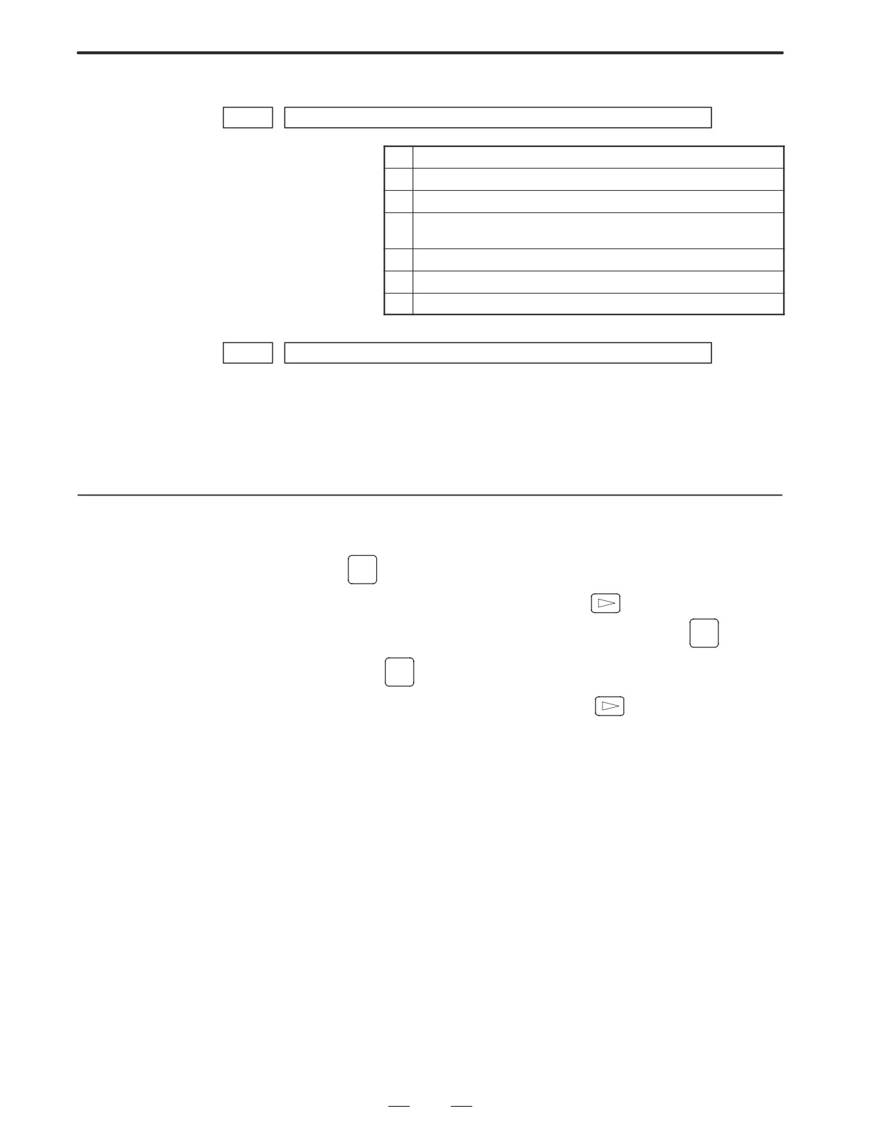
0102
pecification number of input/output device
0
RS-232-C (control codes DC1 to DC4 used)
1
FANUC bubble cassette B1/B2
2
FANUC Floppy cassette adapter F1
3
PROGRAM FILE Mate. FANUC FA card adapter ,FANUC
Floppy cassette adapter, FSP-H
4
Not used
5
Portable tape reader
6
FANUC PPR, FSP-G, FSP-H
0103
Baud Rate
1:
50
5:
200
9:
2400
2:
100
6:
300
l10:
4800
3:
110
7:
600
11:
9600
4:
150
8:
1200
12:
19200 [BPS]
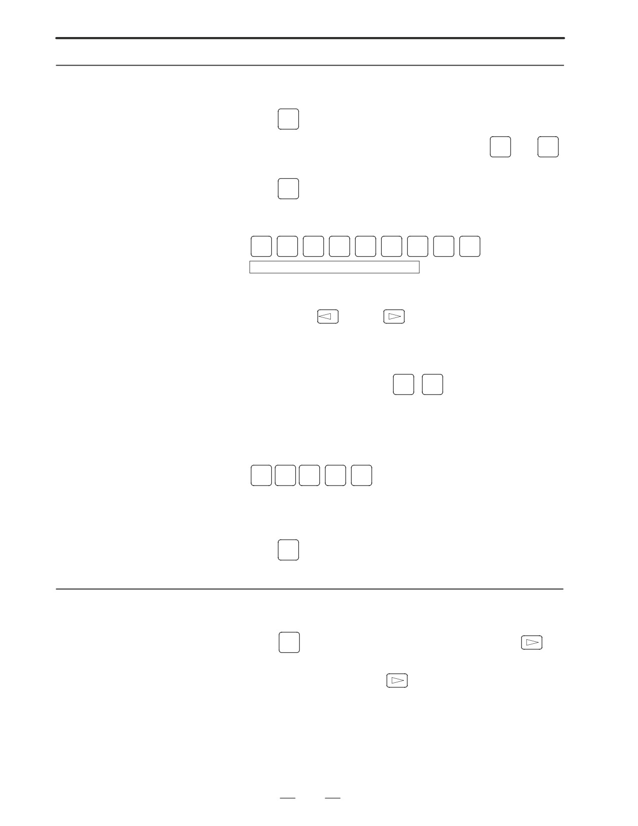
3.2.2
In case of PPR, steps 2 and 3 are not required.
Outputting CNC
1. Select EDIT mode.
Parameters
2.
PROG
Press PROG key and soft key PRGRM to select a program text.
3. Press soft key [(OPRT)] and soft key
And then, put out the head of file by pressing [FSRH]
0
[EXEC].
4. Press
SYSTEM
key and soft key [PARAM] to display parameter screen.
5. Press soft key [(OPRT)] ,and soft key
6. Press soft key [PUNCH] and [EXEC],and the parameters are started
to be output.
181
3. INPUT AND OUTPUT OF DATA
B-63005EN/01
3.2.3
Outputting PMC
1. Select MDI mode.
Parameters
OFFSET
2. Press
SETTING
key then soft key [SETTING] to select a setting screen.
3. Set the cursor to PARAMETER WRITE and input
1
and
INPUT
At this time, alarm 100 will be generated.
4. Press
SYSTEM
key and soft key [PMC].
5. Press soft key [PMCPRM] and soft key [KEEPRL]
6. Set the cursor to K17 and set the first bit to 1.
X
X
X
X
X
X
1
X
INPUT
Where, mark x is a former value
Thus, data input/output screen has been selected.
7. Select EDIT mode.
8. Press soft key
then key
9. Press soft key [I/O] and set the parameters on I/O.
Item selection cursor moves to the following item after data of an item
is set.
10.In CHANNEL NO item, input
1
INPUT
to select I/O channel 1.
11.In DEVICE item, press soft key [FDCAS] to select the floppy cassette.
12.In KIND DATA item, press soft key [PARAM].
13.In FUNCTION item, press soft key [WRITE].
14.In FILE No item, specify a file name. In this example input as follows:
@
P
M
C
INPUT
15.Press soft key [EXEC]. Then PMC parameters are started to be output.
16.After the PMC parameters have been output, set PARAMETER
WRITE to 0.
17.Press
RESET
to release alarm 100.
3.2.4
Outputting Pitch Error
1. Select EDIT mode.
Compensation Amount
2. Press
SYSTEM
key several times, press soft key [PARAM],
and
[PITCH] to select the SETTING screen for pitch error amount.
3. Press soft key [(OPRT)] and
4. Press soft key [PUNCH] and [EXEC], then pitch error compensation
amount is started to be output.
182
3. INPUT AND OUTPUT OF DATA
B-63005EN/01
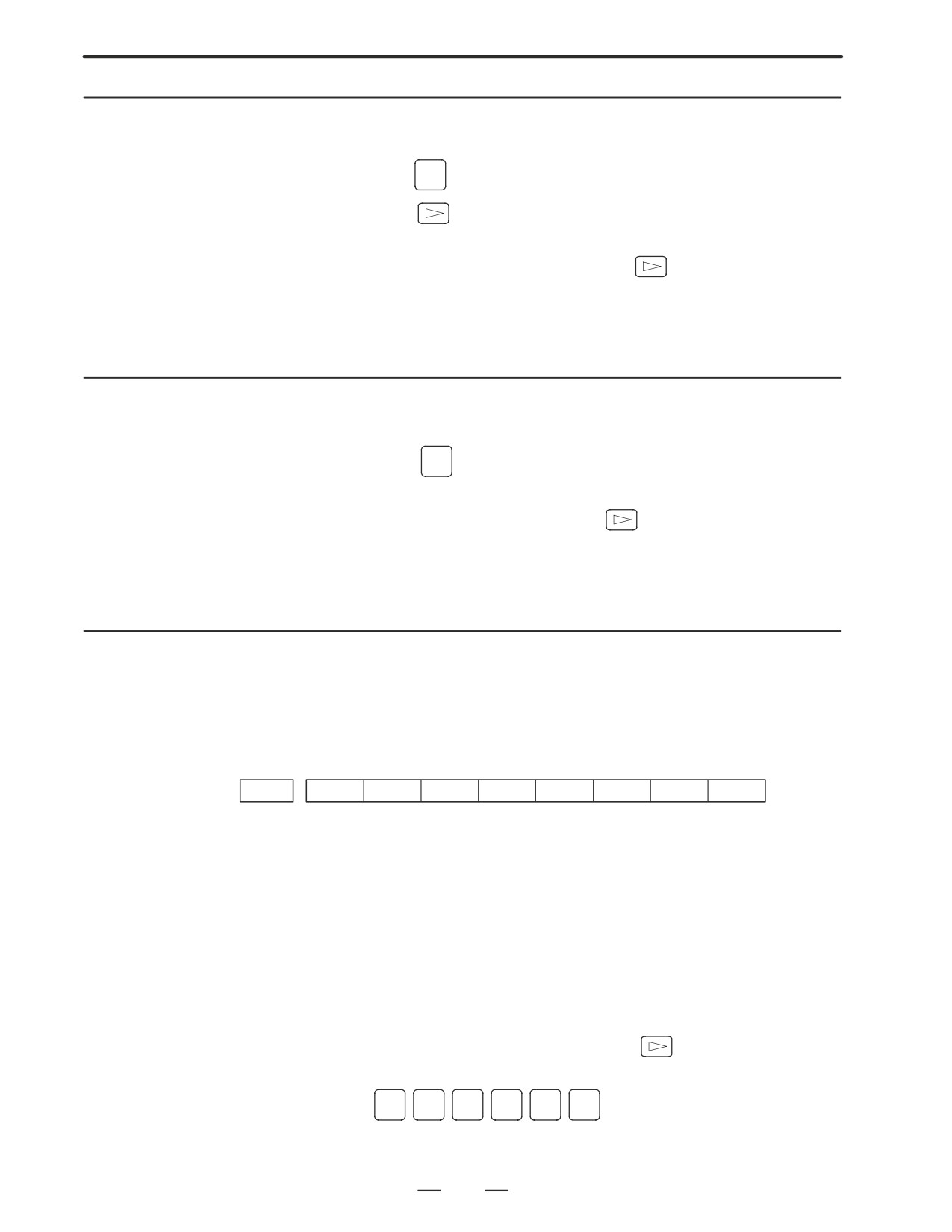
3.2.5
When custom macro function is equipped, values of variable no. 500 and
later are output.
Outputting Custom
Macro Variable Values
OFFSET
1. Press
SETTING
key.
2. Press
key and soft key [MACRO] to select custom macro
variable screen.
3. Press soft key [(OPRT)] and then key
4. Press soft key [PUNCH] and [EXEC], then custom macro variable
values are output.
3.2.6
Outputting Tool
1. Select EDIT mode.
Compensation Amount
OFFSET
2. Press
SETTING
key and soft key
[OFFSET] to display the tool
compensation amount screen.
3. Press [(OPRT)] key and soft key
4. Press soft key [PUNCH] an [EXEC] key, and the tool compensation
amount is started to be output.
3.2.7
Outputting Part Program
1. Confirm the following parameters. If 1 is set, set to the MDI mode and
set it to 0.
#7
#6
#5
#4
#3
#2
#1
#0
3202
NE9
NE8
#4 (NE9) l
0 : Programs of 9000s are edited.
1 : Programs of 9000s can be protected.
#0 (NE8) l
0 : Programs of 8000s are edited.
1 : Programs of 8000s can be protected.
2. Select EDIT mode.
3. Press PROG key and press soft key [PRGRM] to display program
text.
4. Press [(OPRT)] key and press soft key
5. Input a program number to be output. To output all programs input as:
O
-
9
9
9
9
6. Press [PUNCH] and [EXEC] key, then program output is started.
183
3. INPUT AND OUTPUT OF DATA
B-63005EN/01
3.2.8
Inputting CNC
1.
Set to the emergency stop state.
Parameters
2.
Confirm that the patameters required to input data is correct.
1) Press OFFSET/SETTING key several times, and press [SETING]
to display SETTING screen.
2) Confirm that PARAMETER WRITE=1.
3) Press SYSTEM key to select the parameter screen.
4)
0020
Selectionof I/O channel
l 0 : Channel 1 (JD36A of mother board)
1 :
Channel 1
(JD36A of mother board)
2 :
Channel 2
(JD36B of mother board)
3 :
Channel 3
(JD38A of serial communication board)
5)
#7
#6
#5
#4
#3
#2
#1
#0
0101
NFD
ASI
SB2
#7 (NFD)
0 :
Feed is output when punching out.
1 :
Feed is not output when punching out.
#3 (ASI)
0 :
EIA or ISO code is used.
1 :
ASCII code is used.
#0 (SB2)
0 :
No. of stop bits is 1.
l 1 : No. of stop bits is 2.
6)
0102
Specification number of I/O device
0
RS-232-C (control codes DC1 to DC4 are used.)
1
FANUC Bubble cassette B1/B2
2
FANUCFloppy cassette F1
3
PROGRAM FILE Mate, FANUC FA Card adapter, FANUC
Floppy casette adapter, FSP-H, FANUC Handy File
4
Not used
5
Portable tape reader
6
FANUC PPR, FSP-G, FSP-H
184
3. INPUT AND OUTPUT OF DATA
B-63005EN/01
7)
0103
Baud rate
1:
50
5:
200
9:
2400
2:
100
6:
300
l10:
4800
3:
110
7:
600
11:
9600
4:
150
8:
1200
12:
19200 [BPS]
3.
Press soft key [(OPRT)] and soft key
4.
Press soft key [READ] and [EXEC]. Then input of parameters are
started.
5.
Because alarm 300 will generate for the system with absolute pulse
coder, set parameter 1815#5 to 0.
6.
Alarm 300 is issued if the system employs an absolute pulse coder.
In such a case, perform reference position return again.
#7
#6
#5
#4
#3
#2
#1
#0
1815
APCx
#5(APCx)
0 :
Position detector is other than absolute pulse coder.
1 :
Position detector is absolute pulse coder.
7.
After the parameters have been input, turn off the power once then turn
it on.
3.2.9
Set the emergency stop state.
Operation of 12 is not required when PPR is used.
Inputting PMC
1. Turn off (KEY4=1) the program protect key.
Parameters
OFFSET
2. Press
SETTING
key and soft key [SETTING] to select the SETTING
screen.
3. Confirm that PARAMETER WRITE=1.
4. Press
SYSTEM
key and soft key [PMC].
5. Press soft key [PMCPRM] and soft key [KEEPRL].
6. Set the cursor to K17 and set bit 1 to 1.
0
0
0
0
0
0
1
0
INPUT
7. Press
key and
key.
8. Press soft key [I/O] and set the parameters required for I/O.
Item selection cursor displays the next item after an item is set.
9. In CHANNEL item , press
1
INPUT
to select channel 1.
10.In DEVICE item, press [FDCAS] key to select the floppy cassette.
11.In FUNCTION item, press soft key [READ] to input data
12.In FILE NO item, press
2
INPUT
to select file no. 2.
13.Press soft key [EXECT] and the PMC parameters are started to be
input.
14.After data has been read, turn off power and turn it on.
185

3. INPUT AND OUTPUT OF DATA
B-63005EN/01
3.2.10
1. Release the emergency stop and select EDIT mode.
Inputting Pitch Error
2. Confirm that PARAMETER WRITE=1 on the setting screen.
Compensation Amount
3. Press
PROG
key and soft key [PRGRM] to display program contents.
4. Press soft key [(OPRT)],
, [F SRH], and
3
[EXEC] to select
the pitch error compensation file.
5. Press
SYSTEM
key several times, soft key
[PARAM],
and
[PITCH] to select the screen for pitch error compensation amount.
6. Press soft key [(OPRT)] and
key.
7. Press soft key
[READ] and
[EXEC], then the pitch error
compensation amount is started to be input.
OFFSET
8. After data has been input, press
SETTING
key twice to display the
SETTING screen and return the PARAMETER WRITE to 0.
3.2.11
If the system is equipped with the custom macro fucntion, input the
variable values.
Inputting Custom Macro
For PPR, item 4 is not required.
Variable Values
1.
Confirm that EDIT mode is selected.
2.
Turn off the program protect key (KEY2=1).
3.
Press
PROG
key then soft key [PRGRM] to display program contents.
4.
Press soft key [(OPRT)],
, [F SRH], and
4
[EXEC] to select
a file.
5.
Press soft key [(OPRT)] and key
6.
Press address
O
, a program number (0001 for example), soft key
[READ] and [EXEC] key, then custom macro variable values are
started to be input.
Input a program number that is not used.
7.
Select MEMORY mode on the machine operator’s panel and press
cycle start button.
When the program is executed, macro variables are set.
OFFSET
8.
Press
SETTING
key,
key and soft key [MACRO] to select the custom
macro variable screen.
9.
Press 500 and soft key [NO SRH] to display variable number 500 and
confirm the custom macro variables are set correctly.
Of the data displayed, 0 and vacant differ in meaning.
Vacant is an undefined variable. To set vacant, press soft key
[INPUT].
10.Select EDIT mode again.
11.Press
PROG
key to select the program display screen.
186
3. INPUT AND OUTPUT OF DATA
B-63005EN/01
12.Press address O and a program number (0001 for example) ,then press
DELETE
to delete the program.
3.2.12
Item 4 is not required for PPR.
Inputting Tool
1. Select the EDIT mode.
Compensation Amount
2. Turn off the program protect (KEY=1).
3. Press
PROG
key, and press soft key[PRGRM] to display the program
contents screen.
4. Press soft key [(OPRT)],
, [F SRH], and
5
[EXEC] to select
the tool compensation amount file.
OFFSET
5. Press
SETTING
key, and soft key
[OFFSET] to display the tool
compensation amount screen.
6. Press soft key [(OPRT)] and
key.
7. Press [READ] key and [EXEC] key and data input is started.
Confirm the following parameters. If 1 is set, set it to 0.
3.2.13
(Change it in MDI mode).
Inputting Part Programs
#7
#6
#5
#4
#3
#2
#1
#0
3201
NPE
RAL
#6 (NPE)
When programs are registered in part program storage area, M02,M30
and M99 are:
0 : regarded as the end of program.
l
1 : not regarded as the end of porgram.
#1 (RAL)
When programs are registered:
l
0 : All programs are registered.
1 : Only one program is registered.
#7
#6
#5
#4
#3
#2
#1
#0
3202
NE9
NE8
#4 (NE9)
l
0 : Programs of 9000s can be edited.
1 : Programs of 9000s are protected.
#0 (NE8)
l
0 : Programs of 8000s can be edited.
1 : Programs of 8000s are protected.
For PPR, item 4 is not required.
187

3. INPUT AND OUTPUT OF DATA
B-63005EN/01
1. Confirm that mode is EDIT mode.
2. Turn off the program protect (KEY3=1).
3. Press
PROG
key and press soft key [PRGRM] to select a part program
file.
4. Press soft key [(OPRT)],
[F SRH], and
6
[EXEC] to select
a part program file.
5. Press soft
key ,[(OPRT)] and
key.
6. Press soft key [READ] and [EXEC], then data input is started.
188
3. INPUT AND OUTPUT OF DATA
B-63005EN/01
3.3
INPUT/OUTPUT
SUPER CAP DATA
3.3.1
The following operation allows all the data used for Super CAP M to be
input and output in a lump.
Input/Output of
Conversational Data in a
1.
Confirm the parameters shown below:
Lump(Super CAP M)
P0020: I/O CHANNEL (select I/O device)
:
0
P0102: I/O device number
:
3
P0103: Baud rate
for 4800 bauds
:
10
for 9600 bauds
:
11
2.
Select EDIT mode.
3.
Press function key
PROG
and press soft key [CAP].
4.
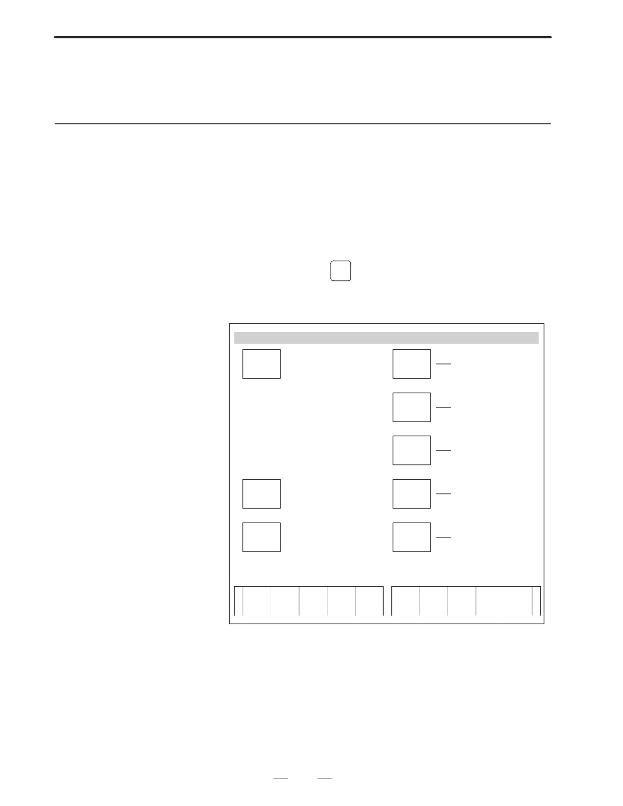
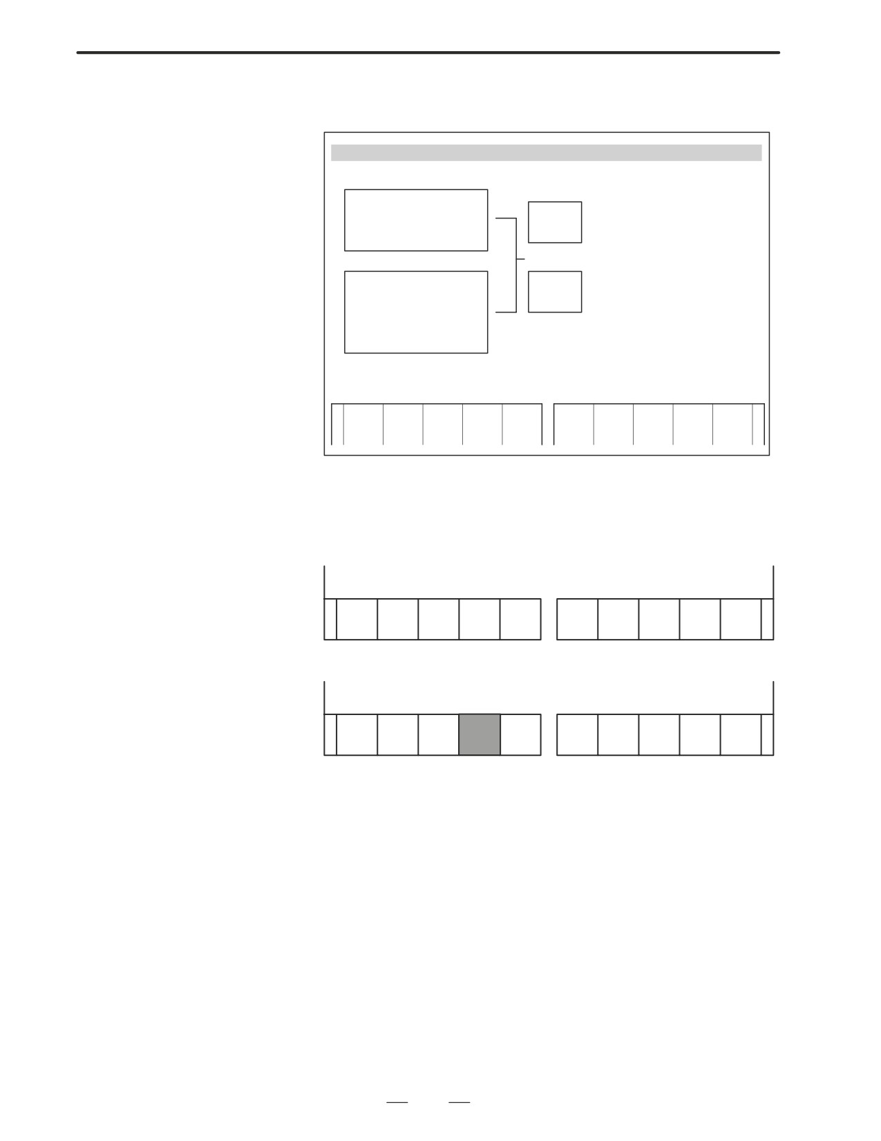
Press soft key [8] (C.A.P DATA) on the basic menu screen.Serial 16i
Conversational Data Screen
C.A.P. DATA
DATA
PRE-
SET DATA OF PRE-
INPUT OR OUTPUT OF DATA
TOOLS BEFORE C.A.P.
I/O
TOOL
PROGRAMMING
TOOL
DISPLAY AND SET
FILE
VARIOUS DATA OF
TOOLS REGISTERED
TOOL
DISPLAY THE DIREC-
DRCTRY
TORY OF TOOLS IN
TOOL FILE
DEF.
DIVIDE
DISPLAY THE DIREC-
DISPLAY DEFAULT DATA
FILE
TOLDIR
TORY OF DIVIDE
TOOLS IN TOOL FILE
DISPLAY A LIST OF TOOL
TOOL
F.S.
DISPLAY AND SET
USED
USED
FILE
DATA OF CUTTING
SET T-ORDER FOR T-OR-
DER CHANGE
CONDITION
SELECT FROM SOFT KEY
<
DATA
DEF.
TOOL
PRE-
TOOL
TOOL
DIVIDE
F.S.
I/O
FILE
USED
TOOL
FILE
DRCTRY
TOLDIR
FILE
5. Press soft key [DATA I/O].
189
3. INPUT AND OUTPUT OF DATA
B-63005EN/01
Series16i Conversational Data Screen
DATA I/O
@ READ
DATA I/O PARA GUIDE
READ
I/O CHANNEL
=0
EXEC
@ PUNCH
I/O DEVICE NO.
=3
OR
@ ALL CAP DATA
PUNCH
@ DEFAULT DATA
EXEC
@ PRE-TOOL LIST
@ TOOL FILE
@ CUT COND FILE
SELECT FROM SOFT-KEY
<
FLOPPY
READ
PUNCH
ALL
DEF.
PRE-
TOOL
F.S.
DIR
DATA
FILE
TOOL
FILE
FILE
6. Press soft key [READ] or [PUNCH].
7. Press soft key [ALL DATA].
8. For read, input a file no. and press soft key [READ EXEC].(Specify
a file no. for all data).
READ FILE NO. =
>
<
FLOPPY
PUNCH
ALL
DEF.
PRE-
F.S.
READ
TOOL
DIR
EXEC
DATA
FILE
TOOL
FILE
FILE
⋅For punch, press soft key [PUNCH EXEC].
SELECT FROM SOFT KEYS
<
FLOPPY
ALL
DEF.
PRE-
F.S.
READ
PUNCH
TOOL
DIR
EXEC
DATA
FILE
TOOL
FILE
FILE
The above operation reads and punches default data, pre-tool list, tool file
and F.S. file in a lump.
190

3. INPUT AND OUTPUT OF DATA
B-63005EN/01
3.3.2
You can input and output files individually.
Execute the same operations from step 1 to 6 in the previous section 3.3.1.
Input and Output of Each
(1) Reading or Punching default files
File (Super CAP M)
7
Press [DEF. FILE].
8
@ For reading, input a file no. for default data and press soft key
[READ EXEC]. (Specify a file number of default file).
@ For punching, press [PUNCH EXEC].
(2) Reading or punching pre-tool list
7
Press PRE-TOOL.
8
@ For reading, press a file number and soft key [READ EXEC].
(Specify a file number of pre-tool list).
@ For punching, press soft key [PUNCH EXEC].
(3) Reading or Punching tool file
7
Press TOOL FILE.
8
@ For reading, press a file number and pres soft key
[READ EXEC]. (Specify file number of tool file).
@ For punching, press [PUNCH EXEC].
(4) Reading or Punching F, S file
7
Press F.S. FILE.
8
@ For reading, press a file no. and press soft key
[READ EXEC].(Specify a file no. of F.S. FILE).
@ For punching, press [PUNCH EXEC].
This feature allows NC parameters, offsets, NC programs, PMC
3.3.3
parameters and so on to be input/output from/to a general I/O device such
Input and output of
as FANUC cassette adapter or the like.
CAP Data
(Super CAP T)
1. Data that can be input/output
(1) NC parameters: All parameters except for optional parameters
and a parameter that specifies the no. of
axes.(No. 1010)
(2) Offset values:
All data of wear/geometry data
(3) NC programs:
All the NC programs
(4) PMC parameters: All data of counter, keep relay, timer and other
data
(5) Tool File:
All data of tool data file, F.S. data, roughness
data, pre-tool list and chuck/tailstock figure
data.
(6) CAP program:
All the CAP program (Cannot input/output
individual program)
CAUTION
You should input/output NC parameters separately. You
can input/output other data in a lump.
191
3. INPUT AND OUTPUT OF DATA
B-63005EN/01
Output of conversutional
Operation for outputting data in a lump
data in a lump
(1) Connect external I/O device and set necessary parameters.
@ Channel at NC side=0
@ Stop bit=2
@ Parity=No
@ Length of character=8
@ Baud rate=Depends on NC parameter no. 0103.
@ XON/OFF control=Yes
(2) Select EDIT mode. For path 2, select screen of tool post 1.
(3) Display basic menu screen, press [+] key to display the 2 nd page
soft keys.
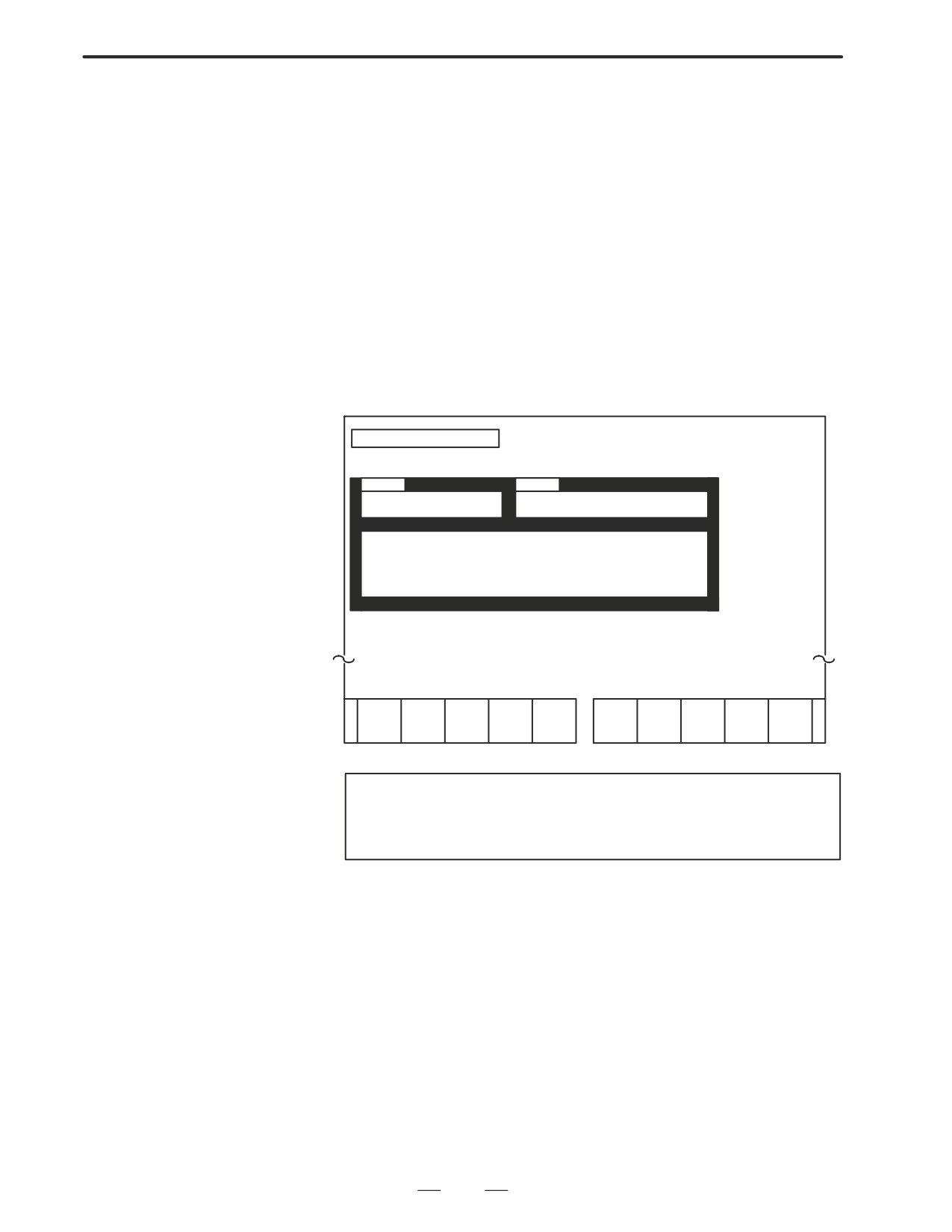
(4) Press [17] to display the following data I/O menu screen.
[Data I/O menu Screen]
DATA I/O SCREEN
[CAP:HEAD-L]
SINGLE
SINGLE
1. NC PARAMETER (HD1)
7. NC PARAMETER (HD2)
2. NC OFFSET (HD1)
5. NC OFFSET (HD2)
8. CAP TOOL FILE
3. NC PROGRAM (HD1)
6. NC PROGRAM (HD2)
9. CAP PROGRAM
4. PMC PARAMETER
<
READ
PUNCH
I/O
SET UP
CAUTION
For one-path control CNC, data select menu on tool post 2
is not displayed.
192
3. INPUT AND OUTPUT OF DATA
B-63005EN/01
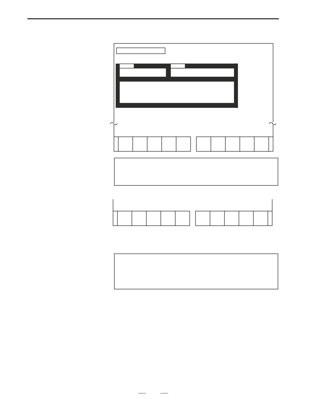
(5) Press [PUNCH] and the following screen is displayed.
DATA I/O SCREEN
[CAP:HEAD-L]
PUNCH
SINGLE
SINGLE
1. NC PARAMETER (HD1)
7. NC PARAMETER (HD2)
2. NC OFFSET(HD1)
5. NC OFFSET(HD2)
8. CAP TOOL FILE
3. NC PROGRAM(HD1)
6. NC PROGRAM(HD2)
9. CAP PROGRAM
4. PMC PARAMETER
SELECT THE DATA WHICH YOU WANT TO PUNCH OUT
<
+
NC
NC
NC
PMC
CAP
CAP-
NC HD2
NC HD2
NC HD2
SELECT
PARAM
OFFSET
PROG
PARAM
TOOL
PROG
PARAM
OFFSET PROG
END
NOTE
For one-path control CNC, the following soft keys are
displayed.
+
<
NC
NC
NC
PMC
CAP
CAP-
I/O
PRE-PG
SELECT
PARAM
OFFSET
PROG
PARAM
TOOL
PROG
SET UP
END
(6) Press a soft key corresponding to data to be output. Selected data
is displayed by green character in reverse video.
Select all the data to be output and press [SELECT END].
CAUTION
NC parameters can be output only separately. If NC
parameters are selected to be output with other data, other
data is canceled.
193
3. INPUT AND OUTPUT OF DATA
B-63005EN/01
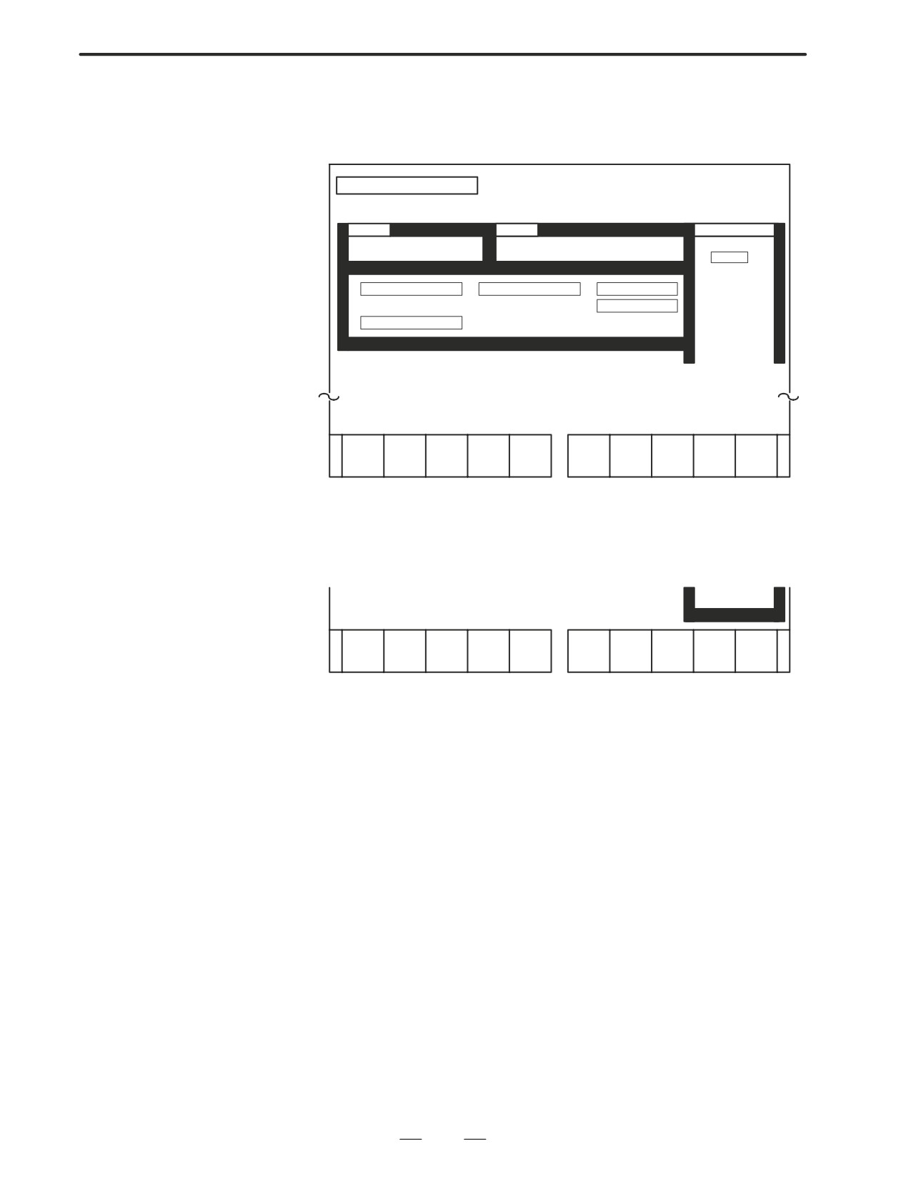
[NC PROG] or [NC HD2 PROG]
(For path 2, when [NC PROG] is pressed, the following screen is
displayed.)
DATA I/O SCREEN
[CAP:HEAD-L]
PUNCH
SINGLE
SINGLE
REGISTEREPROGRAMS
1. NC PARAMETER (HD1)
7. NC PARAMETER (HD2)
***HEAD 1***
00012
00110
00120
2. NC OFFSET (HD1)
5. NC OFFSET (HD2)
8. CAP TOOL FILE
00150
00160
3. NC PROGRAM (HD1) 6. NC PROGRAM (HD2)
9. CAP PROGRAM
4. PMC PARAMETER
SELECT THE DATA WHICH YOU WANT TO PUNCH OUT
<
ALL
ALL
SELECT
CANCEL SELECT
SELECT
CANCEL
END
[ALL SELECT] Press this key to output all the programs.When you
press this key, the following menu is displayed.
EXEC REALLY? YES: [EXEC], NO: [CANCEL]]
<
EXEC
CANCEL
To execute punching all the programs, press [EXEC] and when it is not
needed, press [CANCEL].
[ALL CANCEL]
Press this key to cancel outputting all the data.
When this key is pressed, the same soft key as
when [ALL SELECT] is pressed is displayed.
To execute cancelling, press [EXEC]; to cancel
cancelling, press [CANCEL].
[SELECT]
When you specify a NC program to be punched,
move the cursor to the program number and
press this key.
[CANCEL]
To cancel outputting NC programs, press this
key.
[SELECT END]
When you finsh specification of punching, press
this key.
194
3. INPUT AND OUTPUT OF DATA
B-63005EN/01
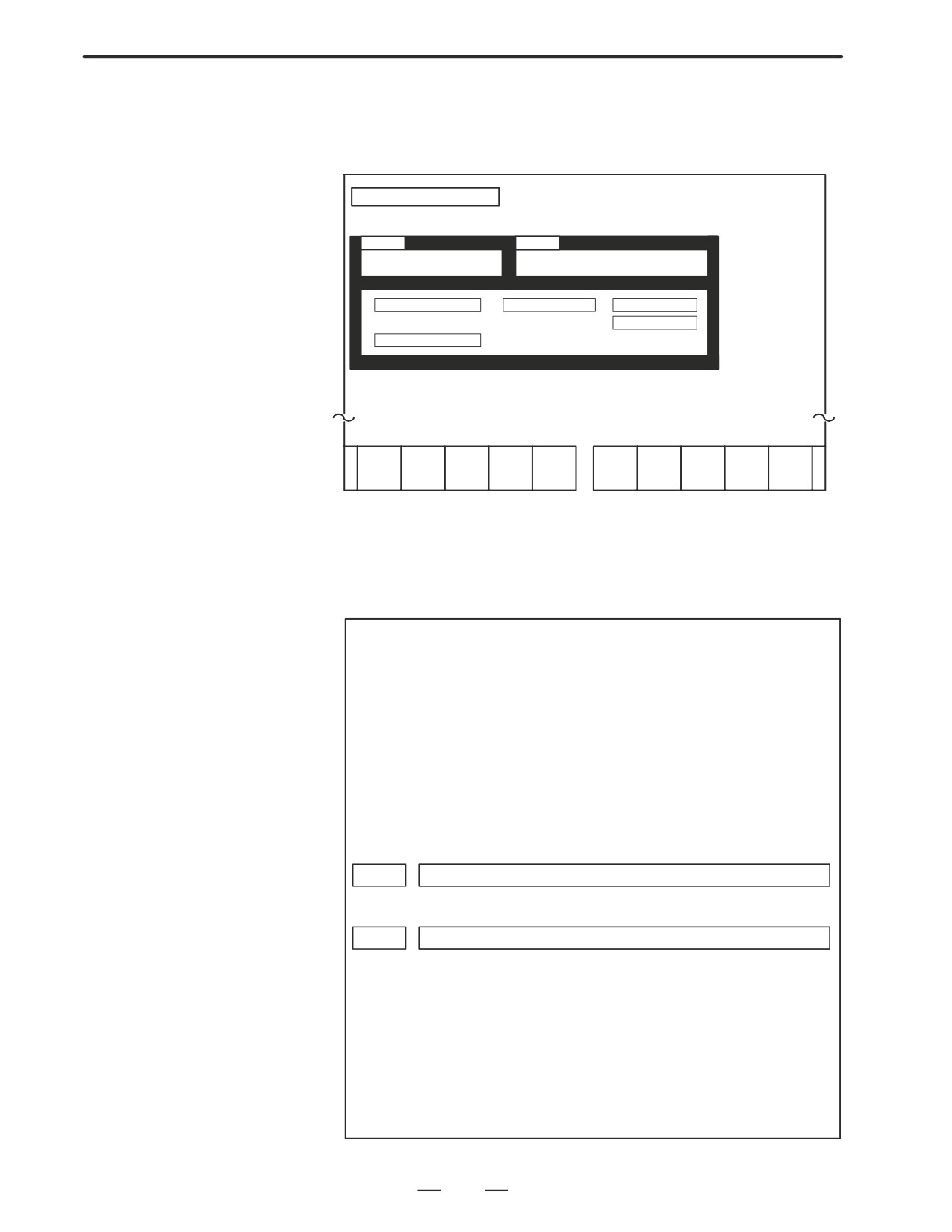
(7) The following screen is displayed when you press [SELECT
END]. To start punching, press [EXEC] and to cancel punching,
press [CANCEL].
DATA I/O SCREEN
[CAP:HEAD-L]
PUNCH
SINGLE
SINGLE
1. NC PARAMETER (HD1)
7. NC PARAMETER (HD2)
2. NC OFFSET (HD1)
5. NCOFFSET (HD2)
8. CAP TOOL FILE
3. NC PROGRAM (HD1)
6. NCPROGRAM (HD2)
9. CAP PROGRAM
4. PMC PARAMETER
EXEC REALLY? YES: [EXEC] NO [CANCEL]
<
I/O
EXEC
CANCEL
SET UP
When data punching starts, “OUTPUTTING” blinks on the lower
right corner of the screen. The data being output is indicated by
blinks of yellow characters in reverse video. When data outputting
finishes, the data is shown in blue color. If outputting finishes with
an error generated, the data is shown in red.
NOTE
1
The data format output by the above funciton is different
from the data format input/output in an individual operation.
Therefore, output data by this function cannot be used for
inputting.
2
Data format is different between 1-path and 2-path for
two-path control.
3
The data that can be input by the input/output in a lump
function is limited to data output by the same function.
4
The range of PMC parameters to be output can be specified
by the following NC parameter.
NC parameter
9090
PMCIOS
PMCIOS
: The start address number of D area of the PMC parameters to be output.
9091
PMCIOE
PMCIOE
: The end address number of D area of PMC parameters to be output.
No.9090(PMCIOS)=0, No.9091(PMCIOE)=0
: All the PMC parameters including keep relays, counters, timers and data
are output.
No.9090(PMCIOS)=No.9091(PMCIOE) : 0
: D area data (one data) of the specified address number is output.
No.9090(PMCIOS) < No.9091(PMCIOE)
: D area data of PMC parameters from the specified starting address
number to the ending address number are output.
No.9090(PMCIOS) > No.9091(PMCIOE)
: All the data in D area are output.
195
3. INPUT AND OUTPUT OF DATA
B-63005EN/01
Input of conversational
Data output by using the function for inputting/outputting data in a lump
data in a lump
can also be input by using that function.
1. Set optional parameters and the parameter for specifying the number
of axes (parameter No. 1010) manually before reading NC parameters.
2. In the same way as output operation, connect an external I/O device
and set necessary parameters, such as device selection.
3. Select EDIT mode. For a two-path system, select the screen for tool
post 1.
4. Release protection for each data item to be input.
1) NC parameter: Set ”PARAMETER WRITE” in the setting data
to 1.
2) Offset: Turn off offset data protection (KEY1 = 1).
3) NC program: Turn off program protection (KEY3 = 1).
4) PMC parameter: Set ”PARAMETER WRITE” in the setting
data to 1.
5) Tool file: Turn off offset data protection (KEY1 = 1).
6) Conversational program: Turn off program protection (KEY3 = 1).
5. Display the data input/output menu screen.
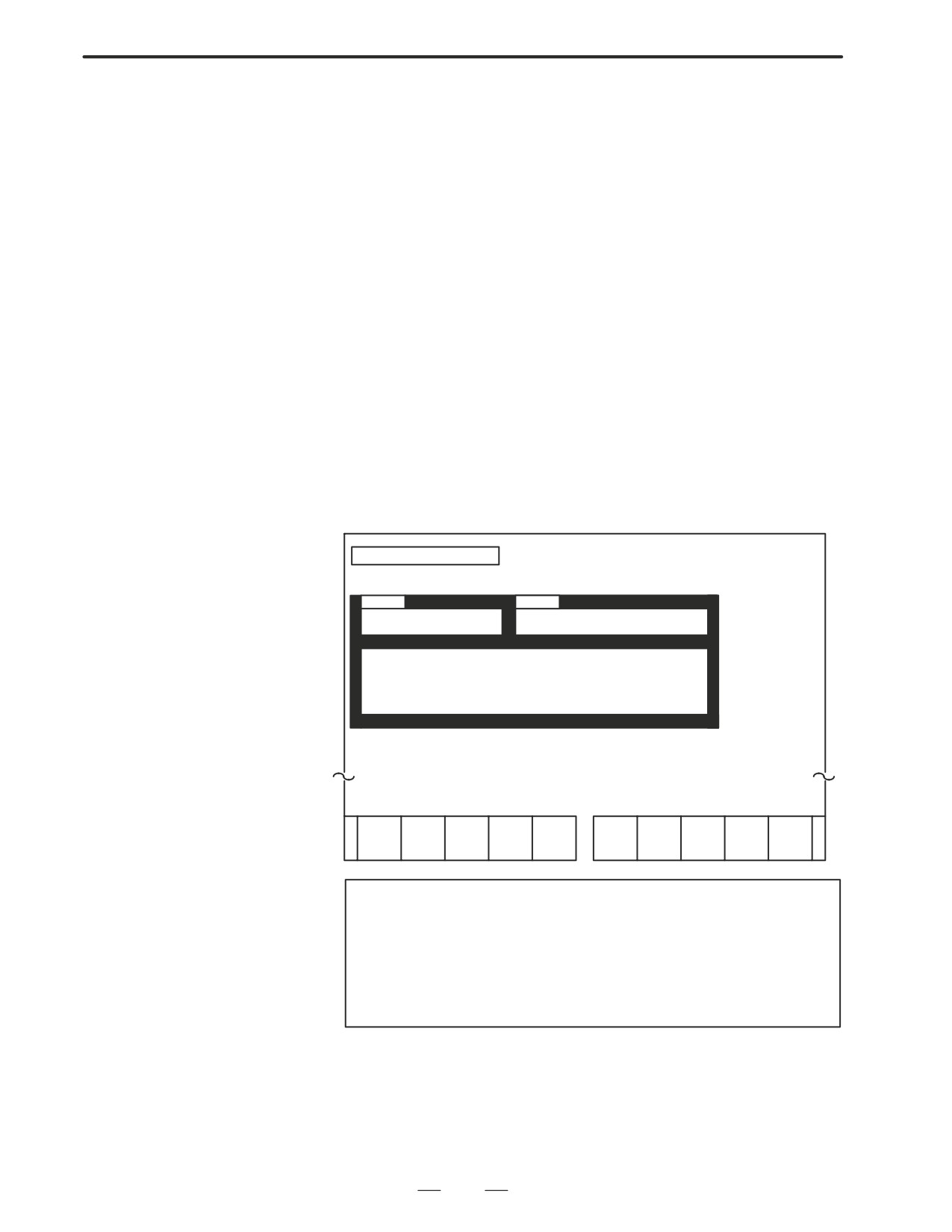
6. Press [READ] to display the following screen.
DATA I/O SCREEN
[CAP:HEAD-L]
READ
SINGLE
SINGLE
1. NC PARAMETER(HD1)
7. NC PARAMETER(HD2)
2. NC OFFSET (HD1)
5. NC OFFSET (HD2)
8. CAP TOOL FILE
3. NC PROGRAM (HD1)
6. NC PROGRAM (HD2)
9. CAP PROGRAM
4. PMC PARAMETER
SELECT THE FILE WHICH YOU WANT TO READ
<
NC
NC HD2
I/O
PRE-
EXE
OTH-
PARAM
PARAM
PARAM
PG
C
ERS
CAUTION
1
For a single-path system, the data selection menu for tool
post 2 is not displayed.
2
When the I/O device is other than the FANUC cassette
adapter, soft keys [NC PARAM], [OTHERS], and [NC HD2
PARAM] are not displayed.
7. Make preparations for the data to be read (including a search for the
beginning of the data) when an I/O device other than the FANUC
cassette adapter is used.
When the FANUC cassette adapter is used, the data can be retrieved
automatically, such that no preparation is required.
196
3. INPUT AND OUTPUT OF DATA
B-63005EN/01
8. To input NC parameters for tool post 1, press [NC PARAM]. To input
NC parameters for tool post 2, press [NC HD2 PARAM].
To input data other than NC parameters, press [OTHERS]. The
selected data is indicated by green characters in reverse video. When
input of data other than parameters is specified, however, all the data
is indicated by green characters in reverse video because the data to be
actually read is not determined beforehand.
9. Press [EXEC] to display the following soft keys.
EXEC REALLY YES:
[EXEC]
NO;
[CANCEL]
<
I/O
EXE
CAN-
SET
C
CEL
UP
10.Press [EXEC] to start data input or press [CAN] to cancel data input.
For data other than NC parameters, if multiple data items have been
output at a time, they can also be input at a time.
During data input, ”INPUTTING” blinks on the lower-right corner
of the screen. The data being input is displayed by blinks of yellow
characters in reverse video. When data input terminates normally, it
is indicated by blue characters; if data input terminates with an error,
the data is indicated by red characters.
197
3. INPUT AND OUTPUT OF DATA
B-63005EN/01
3.3.4
Files can be read and punched individually.
Input and Output of
Each File
(Super CAP T)
Output of conversational
Conversational machining programs can be output and saved to an
machining programs
external memory unit via a reader/punch interface.
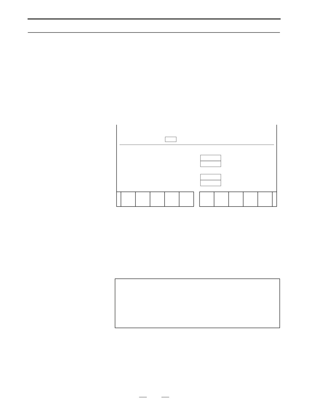
After switching to EDIT mode, display the registered program list screen
for editing. Enter the number of the machining program to be output using
numeric keys, or position the cursor to the program number then press
[PUNCH]. The following soft keys used to confirm operation are
displayed.
PROGRAM NO.
=
1234
³SFTKY
INITAL SET FC25
BAR
PROC(01)
BAR
OUTER END
HEAD-L
ROUGH
T0505
PROC(02)
BAR
OUTER END
HEAD-L
FIN
T0505
PROC(03)
TRANS
PROC(04)
BAR
OUTER END
HEAD-R
ROUGH
T0505
PROC(05)
BAR
OUTER END
HEAD-R
FIN
T0505
<
CAN-
EXE
CEL
C
When [EXEC] is pressed, punch-out of the specified program starts.
When [CAN] is pressed, punch-out operation is canceled and the
previous state is restored.
To output all the machining programs, specify -9999 for the program
number.
When the output device is the FANUC cassette adapter, a new file is
created immediately after the existing files.
Upon the start of outputting machining programs, ”OUTPUTTING”
blinks at the bottom of the screen, until the output operation ends.
NOTE
Only a machining program created with the conversational
input function can be output by applying the above
procedure.
A machining program created using the NC program screen
cannot be output by applying the above procedure.
198
3. INPUT AND OUTPUT OF DATA
B-63005EN/01
Input of conversational
The machining program punched out by applying the procedure described
machining programs
on the previous page can be read into the NC via a reader/punch interface.
Before attempting to read a program, release the memory protect switch
on the machine operator’s panel.
After switching to EDIT mode, display the registered program list screen
for editing, then press [READ]. The following message prompting the
user to input the file number is displayed, as well as the soft keys used to
confirm operation.
PROGRAM NO.
=
³SFTKY
INITAL SET FC25
BAR
PROC(01)
BAR
OUTER END
HEAD-L
ROUGH
T0505
PROC(02)
BAR
OUTER END
HEAD-L
FIN
T0505
PROC(03)
TRANS
PROC(04)
BAR
OUTER END
HEAD-R
ROUGH
T0505
PROC(05)
BAR
OUTER END
HEAD-R
FIN
T0505
<
CAN-
EXE
CEL
C
Enter the number of the file containing the machining program to be input,
using numeric keys, then press [EXEC]. Reading of the machining
program starts. When the input device is FANUC PPR, press [EXEC]
without inputting a file number.
When [CAN] is pressed, read operation is canceled and the previous state
is restored.
Upon the start of inputting machining programs, ”INPUTTING” blinks
at the bottom of the screen, until the input operation ends.
NOTE
Only a machining program created with the conversational
input function can be input by applying the above
procedure.
A machining program created using the NC program screen
cannot be input by applying the above procedure.
199