FANUC Series 16i / 18i / 160i / 180i - Model A. Maintenance Manual (B-63005EN/01) - page 6
2. HARDWARE
B-63005EN/01
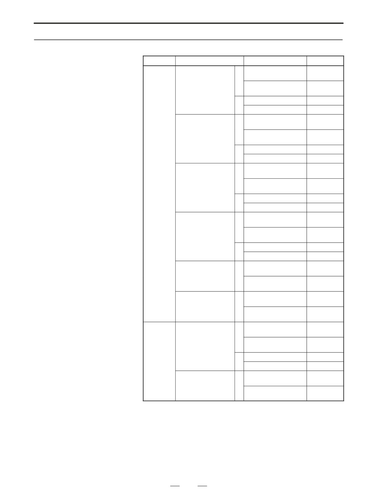
2.4.2
MDI Unit
Model
Name
Drawing number
Remarks
FS16i/18i
Separate-type MDI,
T
A02B-0236-C120#TBR
English keys
small keys
For 8.4”/7.2” LCD
A02B-0236-C120#TBS
Symbolic keys
(horizontal type)
M
A02B-0236-C120#MBR
English keys
A02B-0236-C120#MBS
Symbolic keys
Separate-type MDI,
T
A02B-0236-C121#TBR
English keys
standard keys
For 8.4”/7.2” LCD
A02B-0236-C121#TBS
Symbolic keys
(horizontal/vertical type)
M
A02B-0236-C121#MBR
English keys
A02B-0236-C121#MBS
Symbolic keys
Separate-type MDI,
T
A02B-0236-C125#TBR
English keys
standard keys
For 10.4”/9.5” LCD
A02B-0236-C125#TBS
Symbolic keys
(horizontal type)
M
A02B-0236-C125#MBR
English keys
A02B-0236-C125#MBS
Symbolic keys
Separate-type MDI,
T
A02B-0236-C126#TBR
English keys
standard keys
For 10.4”/9.5” LCD
A02B-0236-C126#TBS
Symbolic keys
(vertical type)
M
A02B-0236-C126#MBR
English keys
A02B-0236-C126#MBS
Symbolic keys
Separate-type MDI
for
T
A02B-0236-C125#TFBR
English keys
CAP-II
For 10.4”/9.5” LCD
A02B-0236-C125#TFBS
Symbolic keys
(horizontal type)
Separate-type MDI,
T
A02B-0236-C126#TFBR
English keys
standard keys
For 10.4”/9.5” LCD
A02B-0236-C126#TFBS
Symbolic keys
(vertical type)
FS160i/180i
Separate-type MDI,
T
A02B-0236-C127#TBR
English keys
standard keys
For 10.4” LCD
A02B-0236-C127#TBS
Symbolic keys
(vertical type)
M
A02B-0236-C127#MBR
English keys
A02B-0236-C127#MBS
Symbolic keys
Separate-type FA full
A02B-0236-C130#EC
English keys
keyboard
For 10.4” LCD
A02B-0236-C130#JC
Japanese keys
(vertical type)
140
2. HARDWARE
B-63005EN/01
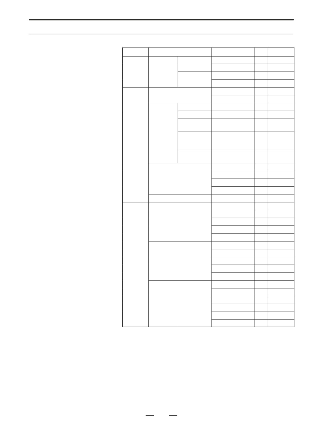
2.4.3
Printed Circuit Boards
Type
Name
Drawing number
ID
Remarks
of the Control Unit
Master PCB
Motherboard
Without per-
A20B-8100-0130
D5
16i
sonal computer
A20B-8100-0135
C5
18i
With personal
A20B-8100-0140
CC
160i
computer
A20B-8100-0145
EC
180i
Card PCB
CPU card
A20B-3300-0050
01
Pentium
A20B-3300-0070
09
486DX2
Display
A
A20B-3300-0020
1E
10.4”, color
control card
B
A20B-3300-0021
1A
8.4”, color
C
A20B-3300-0023
06
9.5”, mono-
chrome
D
A20B-3300-0024
02
7.2”, mono-
chrome,
graphic
E
A20B-3300-0025
03
7.2”, mono-
chrome
Axis control card
A17B-3300-0100
X3
8 axes
A17B-3300-0101
X2
6 axes
A20B-3300-0030
X1
4 axes
A20B-3300-0031
X0
2 axes
Personal computer card
A15L-0001-0052#A
C9
486DX2
DIMM
DRAM module
A20B-3900-0040
87
12M
module
A20B-3900-0041
86
8M
A20B-3900-0042
85
4M
A20B-3900-0030
82
2M
A20B-3900-0031
81
1M
SRAM module
A20B-3900-0020
25
3M
A20B-3900-0060
24
2M
A20B-3900-0061
23
1M
A20B-3900-0052
22
512K
A20B-3900-0053
21
256K
FROM module
A20B-3900-0010
47
16M
A20B-3900-0011
45
12M
A20B-3900-0012
43
8M
A20B-3900-0013
42
6M
A20B-3900-0014
41
4M
A20B-3900-0015
40
2M
141
2. HARDWARE
B-63005EN/01
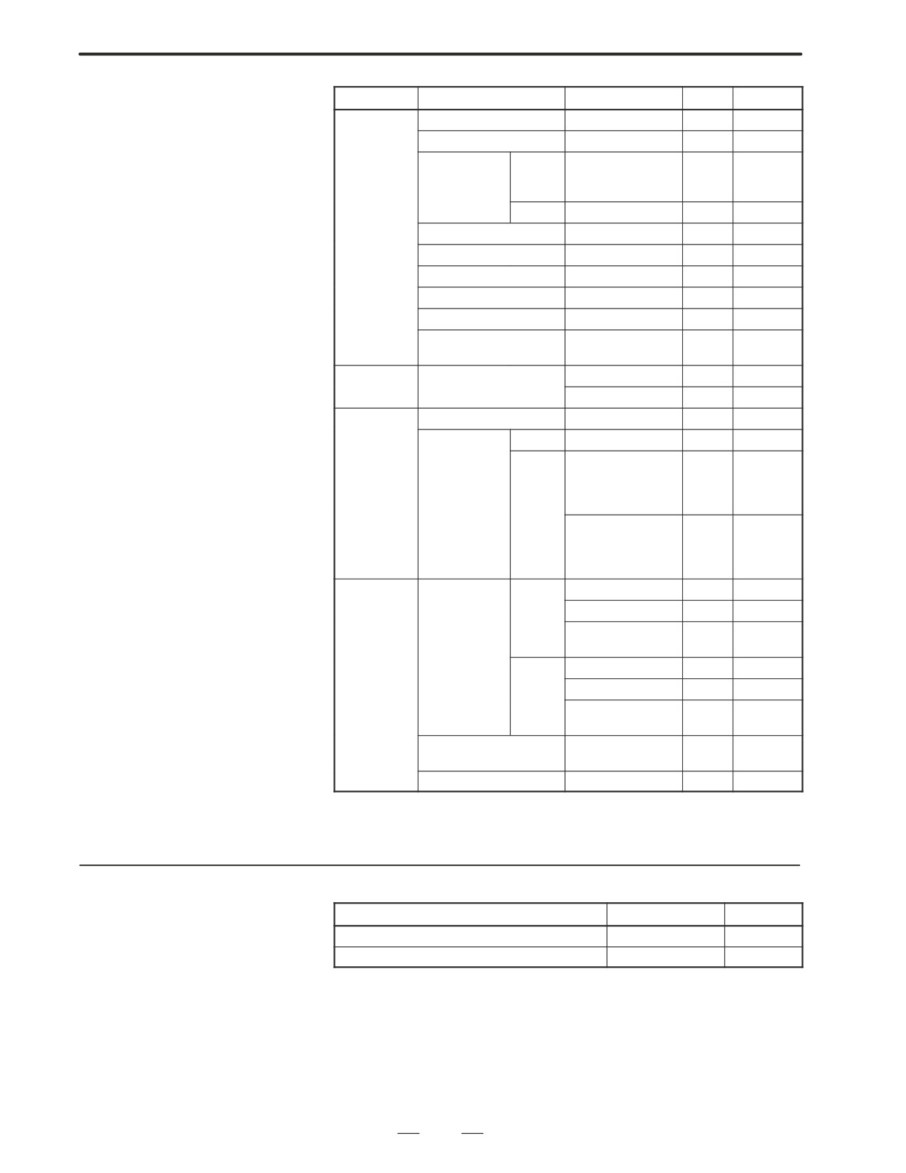
Type
Name
Drawing number
ID(*1)
Remarks
Option PCB
PMC-RE board
A20B-8100-0150
1xCD
C language board
A20B-8100-0151
0xCD
Serial commu-
A
A20B-8100-0152
2xCD
Remote
nication board
buffer/
DNC2
B
A20B-8100-0153
3xCD
DNC1
CAP-II board
A20B-8100-0154
4xCD
Sub-CPU board
A20B-8001-0630
0xCE
RISC board
A20B-8100-0170
0xCF
Data server board
A20B-8100-0160
1xA3
Loader control board
A20B-8100-0190
0xD3
HSSB interface board
A20B-8001-0640
0xAA
(on CNC side)
Back panel
Back panel
A20B-2100-0220
-
2 slots
A20B-2100-0230
-
4 slots
Distributed
I/O card for operator’s panel
A20B-2002-0470
-
I/O
I/O card for con-
Basic
A20B-2100-0150
-
nector panel
Expan-
A20B-2002-0400
-
With
sion
manual
pulse gen-
erator
A20B-2002-0401
-
Without
manual
pulse gen-
erator
Others
Inverter
For units
A20B-2002-0500
-
10.4”, color
with
A20B-2002-0501
-
8.4”, color
no slots/
2 slots
A20B-2002-0480
-
Mono-
chrome
For units
A20B-8100-0200
-
10.4”, color
with
A20B-8100-0201
-
8.4”, color
4 slots
A20B-2002-0550
-
Mono-
chrome
External I/O board for load-
A20B-2002-0620
-
er control
Touch pad control board
A20B-8001-0620
-
*1 x: Printed circuit board version
2.4.4
Others
Name
Drawing number
Remarks
Linear Scale interface unit (basic 4 axes)
A02B-0236-C201
Linear Scale interface unit (additional 4 axes)
A02B-0236-C202
142
2. HARDWARE
B-63005EN/01
2.5
REPLACING THE
WARNING
MOTHERBOARD
Only those personnel who have received approved safety
and maintenance training may perform this replacement
work.
When opening the cabinet and replacing the board, be
careful not to touch the high-voltage circuits (marked and
fitted with an insulating cover). Touching the uncovered
high-voltage circuits presents an extremely dangerous
electric shock hazard.
CAUTION
Before starting replacement work, back up the contents
(such as parameters and programs) of the SRAM memory
of the CNC. Otherwise, the contents of the SRAM memory
may be lost during replacement work.
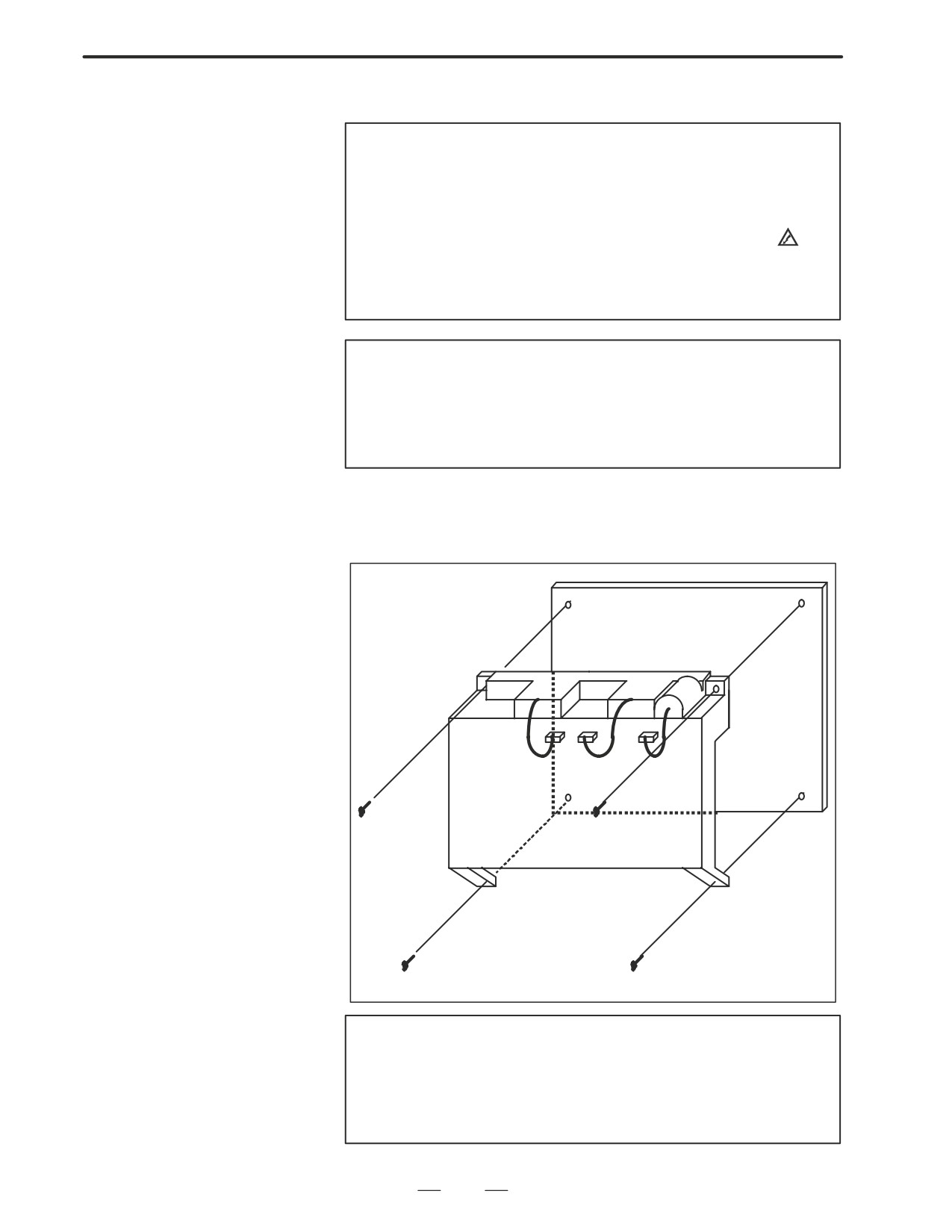
D Replacement procedure
1) Unplug the connectors for the fans and memory backup battery from
the top of the CNC unit, then remove the yellow cover.
CAUTION
With a CNC unit that has an indicator for the touch pad, the
connectors CN1 and CD37 connected to the left side of the
unit, as viewed from the rear of the unit, must be unplugged
before removing the yellow cover.
143
2. HARDWARE
B-63005EN/01
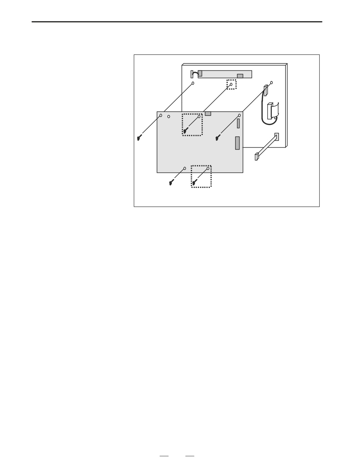
2) Unplug the connectors MCRD1 (or PCMCIA2), CN3, and CN8 from
the printed circuit board, then replace the motherboard.
PCB
CP1
CN3
CN3
CN8
Motherboard
MCRD1
or
PCMCIA2
Flat cable for soft keys
Note) The screws enclosed in dotted boxes are
provided only on the 10.4” LCD unit.
144
2. HARDWARE
B-63005EN/01
2.6
MOUNTING AND
WARNING
DEMOUNTING CARD
Only those personnel who have received approved safety
PCBS
and maintenance training may perform this replacement
work.
When opening the cabinet and replacing a card PCB, be
careful not to touch the high-voltage circuits (marked and
fitted with an insulating cover). Touching the uncovered
high-voltage circuits presents an extremely dangerous
electric shock hazard.
CAUTION
Before starting replacement work, back up the contents
(such as parameters and programs) of the SRAM memory
of the CNC. Otherwise, the contents of the SRAM memory
may be lost during replacement work.
145
2. HARDWARE
B-63005EN/01
2.6.1
Demounting a Card
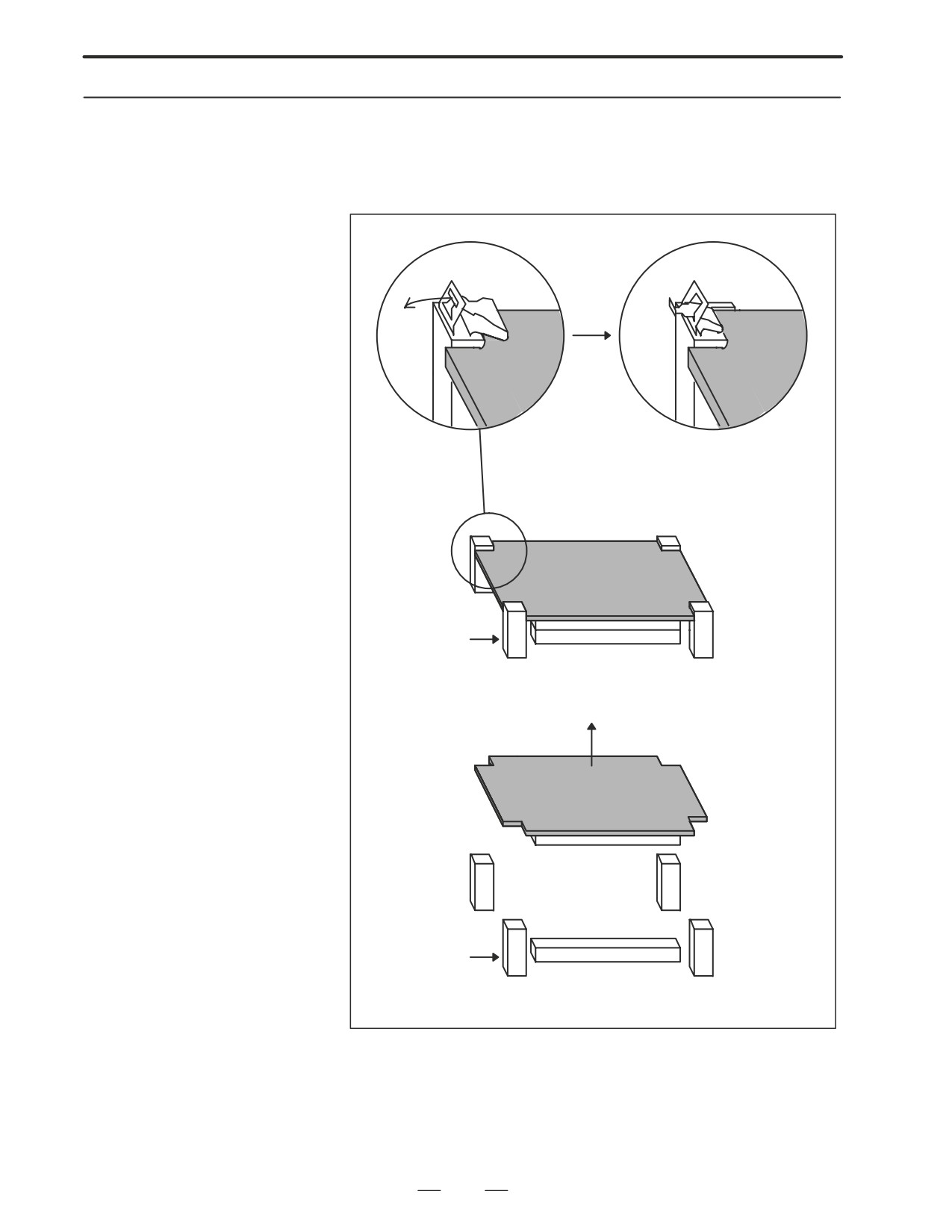
1) Pull outward the claw of each of the four spacers used to secure the
card PCB, then release each latch. (See Fig. a.)
PCB
2) Extract the card PCB upward. (See Fig. b.)
Card PCB
Card PCB
Card PCB
Fig. a Spacer
Connector
Card PCB
Fig. b Spacer
Connector
146
2. HARDWARE
B-63005EN/01
2.6.2
Mounting a Card PCB
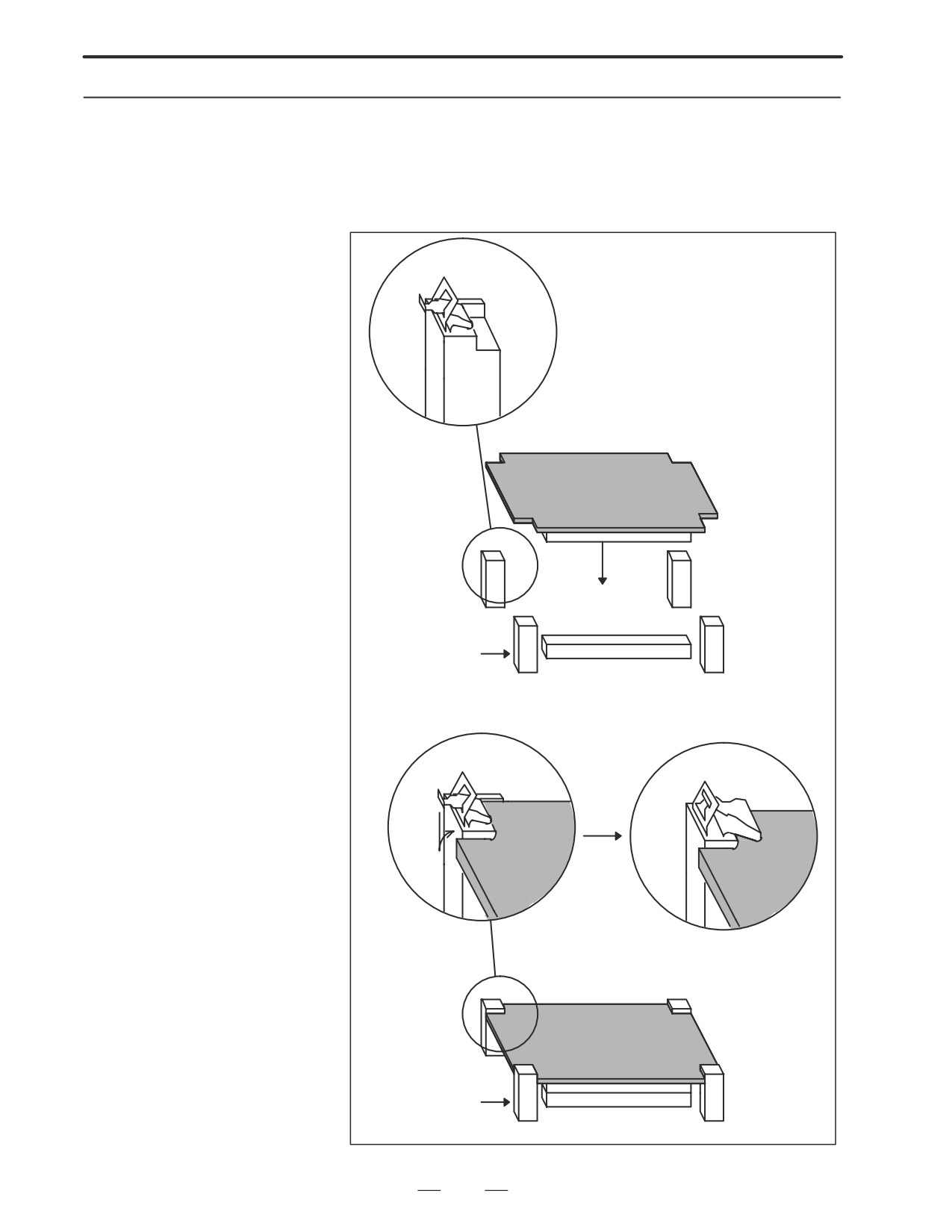
1) Check that the claw of each of the four spacers is latched outward, then
insert the card PCB into the connector. (See Fig. c.)
2) Push the claw of each spacer downward to secure the card PCB. (See
Fig. d.)
Card PCB
Fig. c Spacer
Connector
Card PCB
Card PCB
Card PCB
Fig. d Spacer
Connector
147
2. HARDWARE
B-63005EN/01
2.7
MOUNTING AND
WARNING
DEMOUNTING DIMM
Only those personnel who have received approved safety
MODULES
and maintenance training may perform this replacement
work.
When opening the cabinet and replacing a module, be
careful not to touch the high-voltage circuits (marked and
fitted with an insulating cover). Touching the uncovered
high-voltage circuits presents an extremely dangerous
electric shock hazard.
CAUTION
Before starting replacement work, back up the contents
(such as parameters and programs) of the SRAM memory
of the CNC. Otherwise, the contents of the SRAM memory
may be lost during replacement work.
Before replacing an SRAM module, be sure to back up the
contents of the SRAM module.
148
2. HARDWARE
B-63005EN/01
2.7.1
Demounting a DIMM
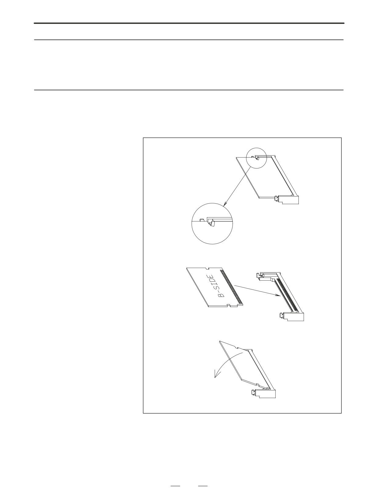
1) Open the claw of the socket outward. (See Fig. a.)
Module
2) Extract the module slantly upward. (See Fig. b.)
2.7.2
Mounting a DIMM
1) Insert the module slantly into the module socket, with side B facing
upward. (See Fig. b.)
module
2) Push the module downward until it is locked. (See Fig. c.)
Fig. a
Fig. b
Fig. c
149
2. HARDWARE
B-63005EN/01
2.8
REPLACING FUSE ON
WARNING
CONTROL UNIT
Before replacing a blown fuse, locate and remove the cause
of the blown fuse.
For this reason, only those personnel who have received
approved safety and maintenance training may perform this
replacement work.
When opening the cabinet and replacing a fuse, be careful
not to touch the high-voltage circuits (marked
and fitted
with an insulating cover).
Touching the uncovered
high-voltage circuits presents an extremely dangerous
electric shock hazard.
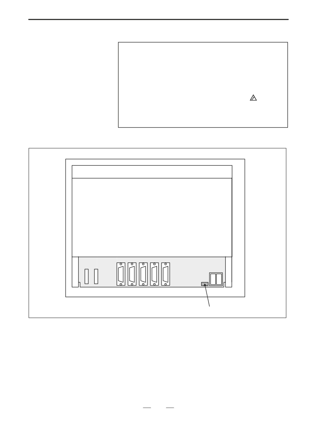
D Fuse mounting location
of the FS16/18i
Rear of unit
CP1A
CP1B
FUSE
Fuse
150
2. HARDWARE
B-63005EN/01
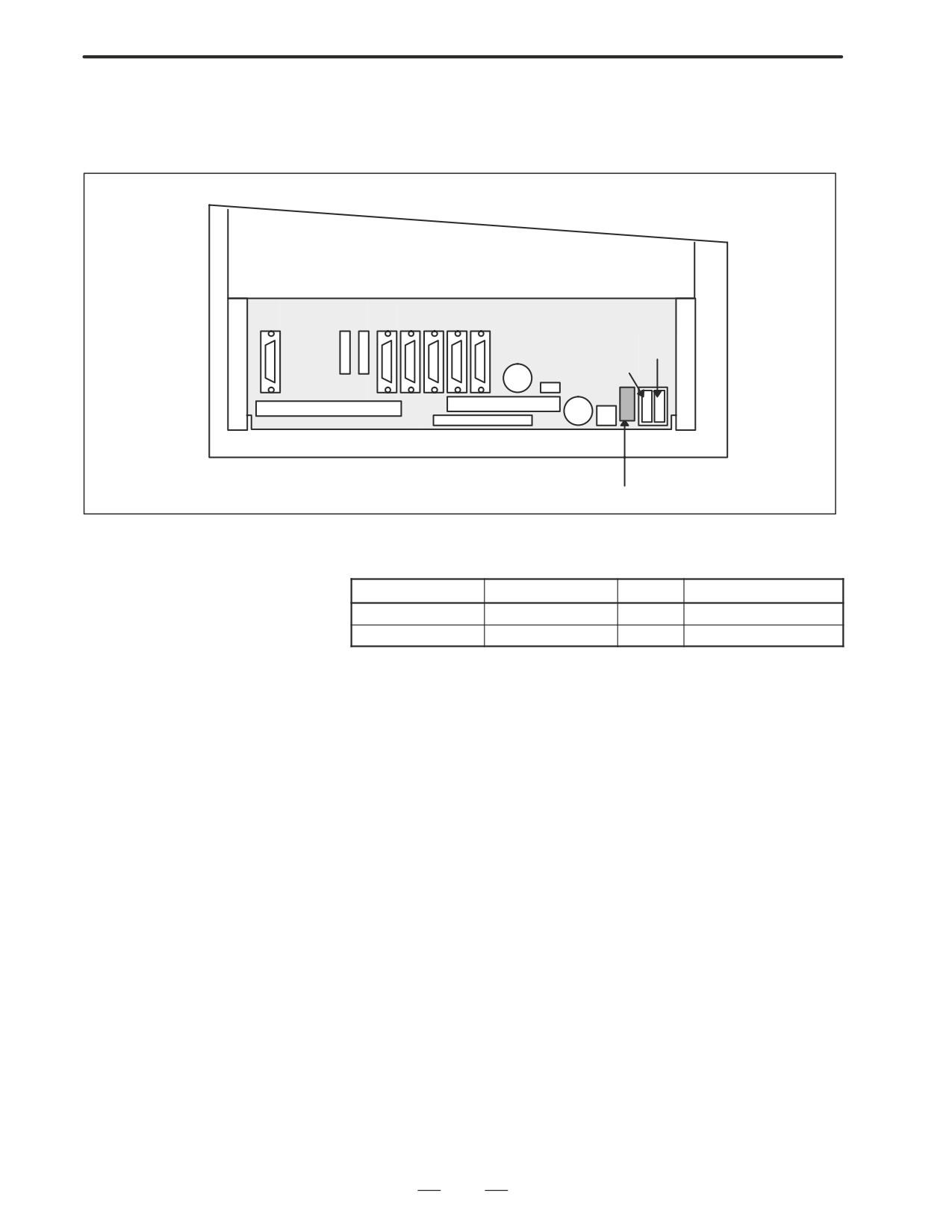
D Fuse mounting location
of the FS160i/180i with
the PC function
Rear of unit
CP1A
CP1B
FUSE
Fuse
D Ordering codes of fuses
Basic unit
Ordering code
Rating
Parts specification
FS16/18i
A02B-0236-K100
5A
A60L-0001-0290#LM50
FS160/180i
A02B-0236-K101
7.5A
A60L-0001-0046#7.5
151
2. HARDWARE
B-63005EN/01
2.9
REPLACING
BATTERY
D Replacement procedure
When a lithium battery is used
Prepare a new lithium battery
(ordering code: A02B-0200-K102
(FANUC specification: A98L-0031-0012)).
1) Turn on the power to the CNC. After about 30 seconds, turn off the
power.
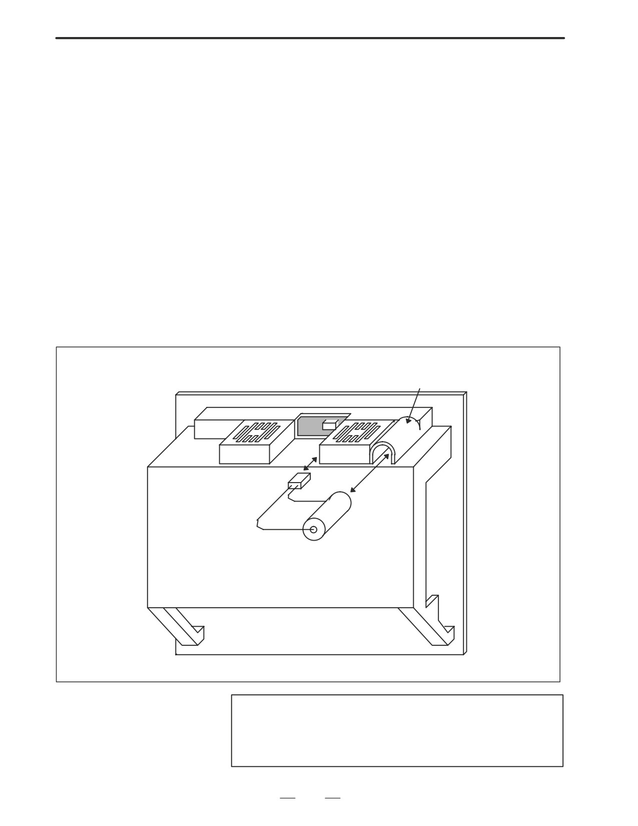
2) Remove the old battery from the top of the CNC control unit.
First, unplug the battery connector, then take the battery out of its
case.
The battery case of a control unit without option slots is located at the
top end of the unit as shown in the figure of the previous page. The
battery case of a control unit with 2 slots or 4 slots is located in the
central area of the top of the unit (between fans).
3) Insert a new battery and reconnect the connector.
Battery case
Connector
Lithium battery
A02B-0200-K102
WARNING
Using other than the recommended battery may result in the
battery exploding. Replace the battery only with the
specified battery (A02B-0200-K102).
152
2. HARDWARE
B-63005EN/01
CAUTION
Steps 1) to 3) should be completed within 30 minutes (or
within 5 minutes for the 160i/180i with the PC function). Do
not leave the control unit without a battery for any longer
than the specified period. Otherwise, the contents of
memory may be lost.
If steps 1) to 3) may not be completed within 30 minutes,
save all contents of the CMOS memory to the memory card
beforehand. Thus, if the contents of the CMOS memory are
lost, the contents can be restored easily.
For the method of operation, refer to the maintenance
manual.
Dispose used batteries as described below.
(3) Small quantities (several batteries)
Discharge the batteries and dispose of them as ordinary unburnable
waste.
(4) Large quantities
Contact FANUC for the method of disposal.
153
2. HARDWARE
B-63005EN/01
When using commercial
alkaline dry cells (size D)
D Method of connection
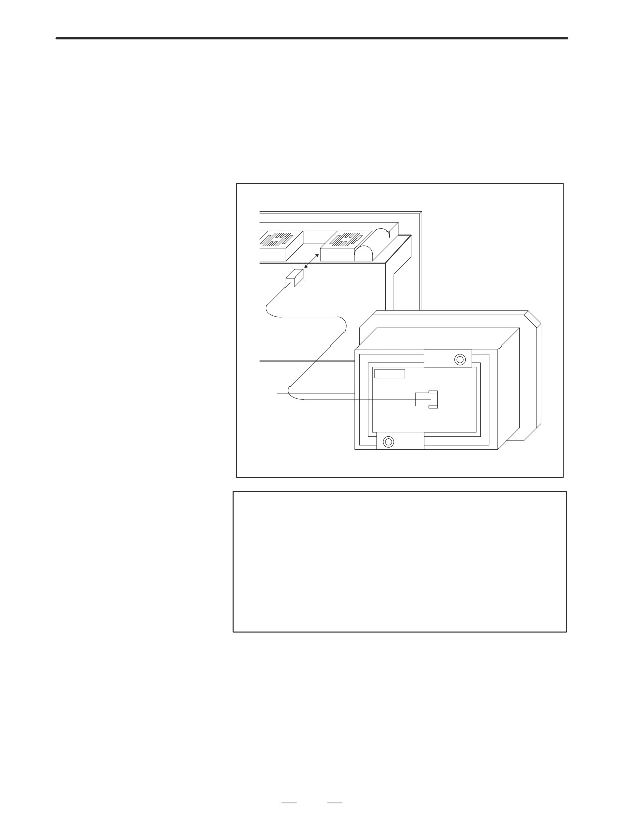
Power from the external batteries is supplied through the connector to
which the lithium battery is connected.
The lithium battery, provided as standard, can be replaced with external
batteries in the battery case (A02B-0236-C281) according to the battery
replacement procedure described above.
CAUTION
1
Install the battery case (A02B-0236-C281) in a location
where the batteries can be replaced even when the power
to the control unit is on.
2
The battery cable connector is attached to the control unit
by means of a simple lock system. To prevent the connector
from being disconnected due to the weight of the cable or
tension within the cable, fix the cable section within 50 cm
of the connector.
154
2. HARDWARE
B-63005EN/01
Replacing
commercial alkaline dry
cells (size D)
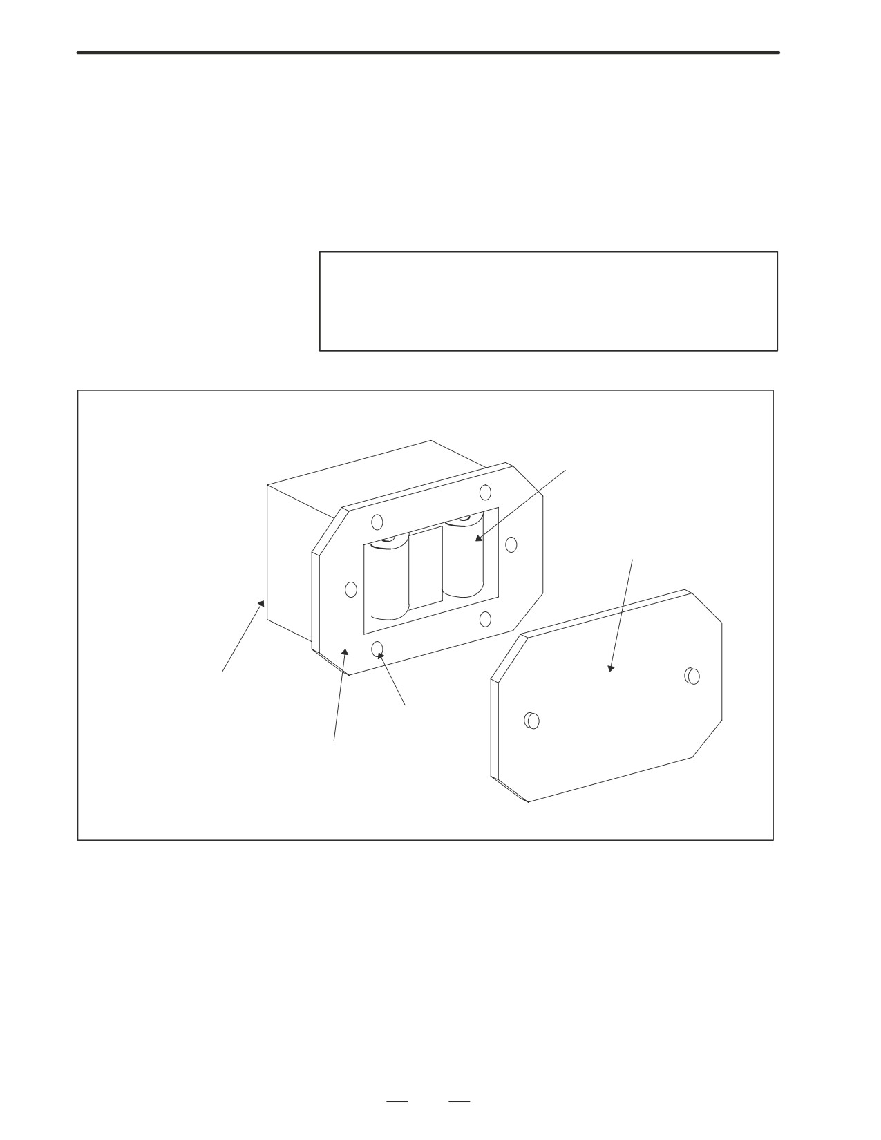
1) Prepare two alkaline dry cells (size D) commercially available.
2) Turn on the power to the Series 16i/18i/160i/180i.
3) Remove the battery case cover.
4) Replace the cells, paying careful attention to their orientation.
5) Reinstall the cover onto the battery case.
CAUTION
When replacing the alkaline dry cells while the power is off,
use the same procedure as that for lithium battery
replacement described above.
Alkaline dry cell x 2
Cover
Connection terminal on the rear
Mounting hole x 4
Battery case
155
2. HARDWARE
B-63005EN/01
2.10
REPLACING FAN
WARNING
MOTORS
When opening the cabinet and replacing a fan motor, be
careful not to touch the high-voltage circuits (marked and
fitted with an insulating cover).
Touching the uncovered high-voltage circuits presents an
extremely dangerous electric shock hazard.
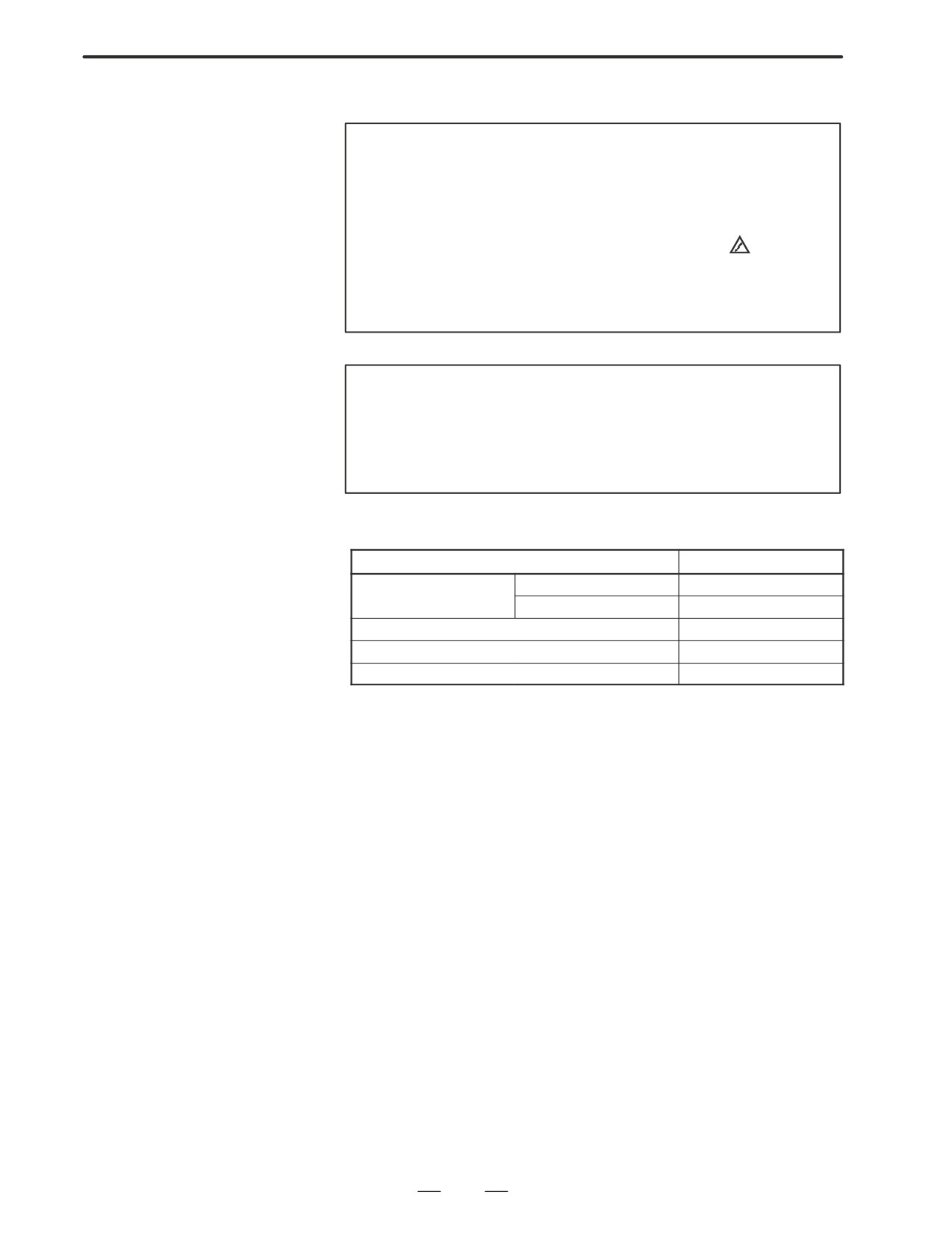
D Fan ordering information
Ordering code
Required quantity
For units with no expansion slots
A90L-0001-0441
2
For units with 2 expansion slots
A90L-0001-0423#105
2
For units with 4 expansion slots
A90L-0001-0423#105
4
Replacement procedure
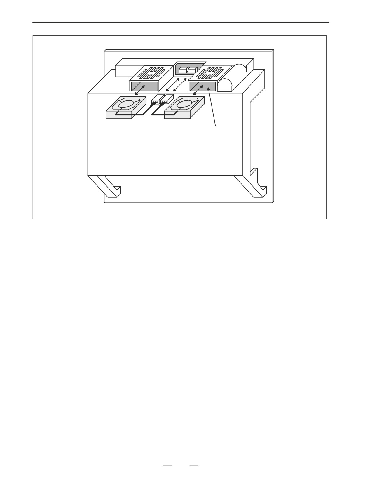
D For units with no
expansion slots and
1. Before replacing a fan motor, turn off the power to the CNC.
units with 2 expansion
slots
2. Unplug the connector of a fan motor to be replaced ( (1) of Fig. a).
The connector is latched. So, when unplugging the connector, hold
down the latch placed at the lower part of the connector with a
flat-blade screwdriver.
3. Detach the latch securing the fan motor, then demount the fan motor
( (2) of Fig. a).
4. Insert a new fan motor into the fan case ( (3) of Fig. a), then reconnect
the connector.
156
2. HARDWARE
B-63005EN/01
Fig. a
(1) Connector
(2) Fan
(3) Fan case
Note) Install a fan so that it flows air in the upward
direction.
(Face the label upward.)
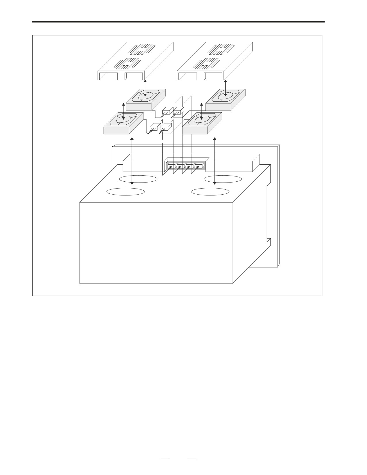
D For units with 4
expansion slots
1. Before replacing a fan motor, turn off the power to the CNC.
2. Unplug the connector of a fan motor to be replaced ( (1) of Fig. b).
The connector is latched. So, when unplugging the connector, hold
down the latch placed at the lower part of the connector with a
flat-blade screwdriver.
3. Detach the latch securing the fan cover ( (3) of Fig. b), then demount
the fan cover from the unit.
4. The fan is secured to the fan cover. Detach the latch, then demount
the fan motor ( (2) of Fig. b).
5. Install a new fan motor onto the fan cover. Then, reinstall the fan
cover onto the unit, and reconnect the connector.
157
2. HARDWARE
B-63005EN/01
Fig. b
(3) Fan cover
(2) Fan
(1) Connector
Note) Install a fan so that it flows air in the up-
ward direction. (Face the label upward.)
158
2. HARDWARE
B-63005EN/01
2.11
REPLACING LCD
WARNING
BACKLIGHT
Only those personnel who have received approved safety
and maintenance training may perform this replacement
work.
When opening the cabinet and replacing a unit, be careful
not to touch the high-voltage circuits (marked
and fitted
with an insulating cover).
Touching the uncovered high-voltage circuits presents an
extremely dangerous electric shock hazard.
CAUTION
Before starting replacement work, back up the contents
(such as parameters and programs) of the SRAM memory
of the CNC. Otherwise, the contents of the SRAM memory
may be lost during replacement work.
D Backlight ordering
information
Backlight
Ordering code
For 7.2” LCD unit
Manufactured by Hitachi
A61L-0001-0142#BL
Manufactured by Sharp
A61L-0001-0142#BLS
For 8.4” LCD unit
A61L-0001-0162#BL
For 9.5” LCD unit
A61L-0001-0154#BL
For 10.4” LCD unit
A61L-0001-0163#BL
159
2. HARDWARE
B-63005EN/01
D Replacement procedure
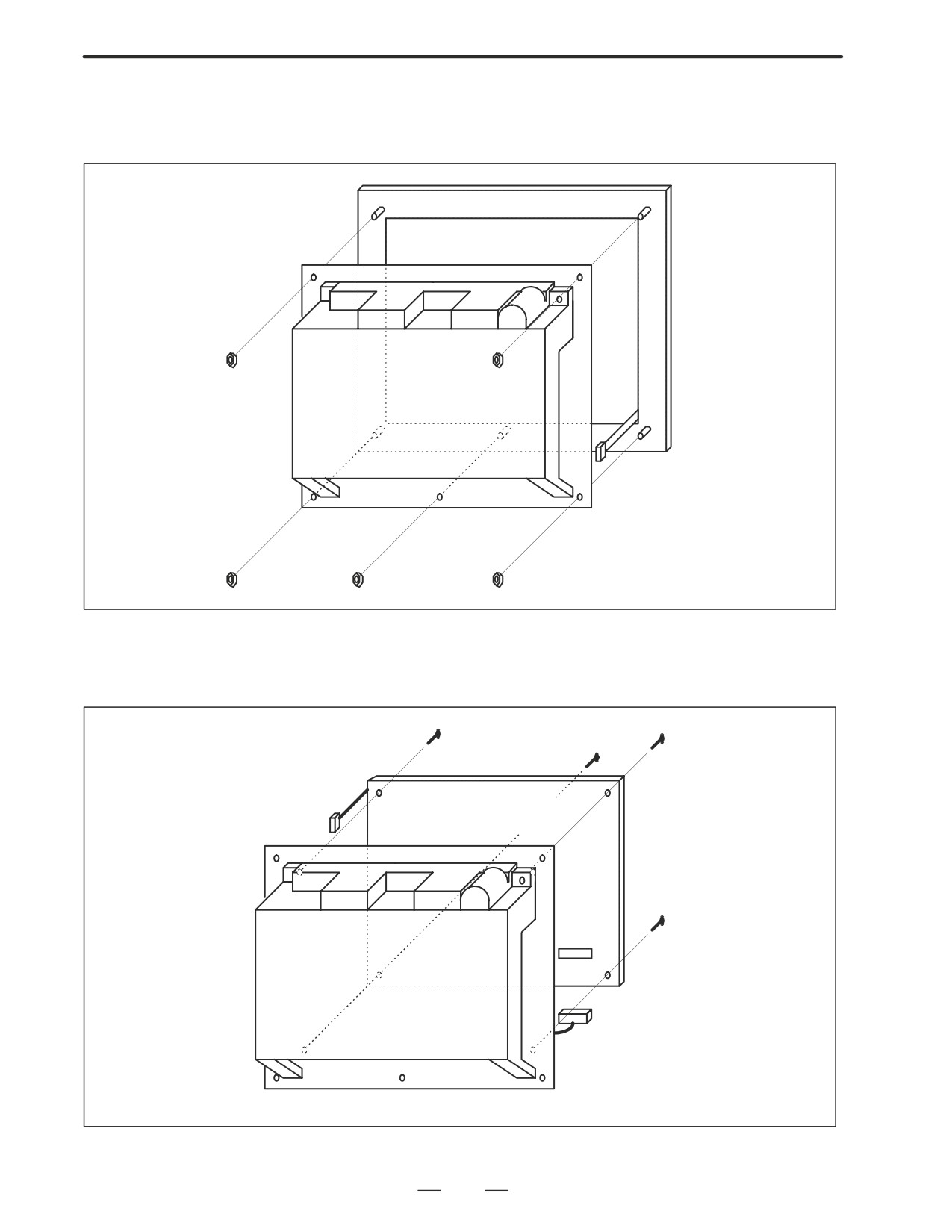
1) Detach the escutcheon from the CNC.
Escutcheon
Flat cable for soft keys
2) As shown below, unplug the connectors CP1 and CN8 to detach the
LCD unit from the CNC unit.
LCD unit
CP1
CN8
CN8
160
2. HARDWARE
B-63005EN/01
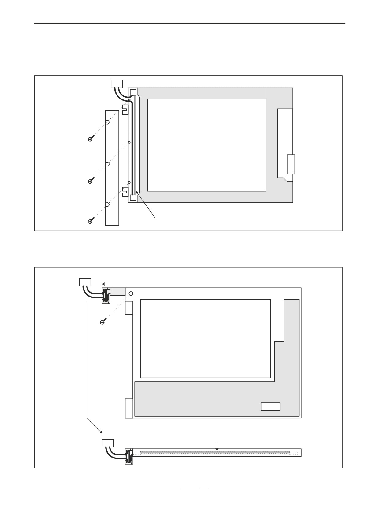
3)-1 For the 8.4” LCD unit (color)
Remove the three screws from the left part on the rear of the LCD unit,
and remove the cover. Then, the backlight is exposed. Replace the
backlight with a new one.
Rear of LCD unit
CN8
Backlight
3)-2 For the 10.4” LCD unit (color)
As shown below, remove the screw, and pull out the case containing
the backlight. Replace the backlight with a new one.
Connector
Rear of LCD unit
PCB
CN8
Backlight
161
2. HARDWARE
B-63005EN/01
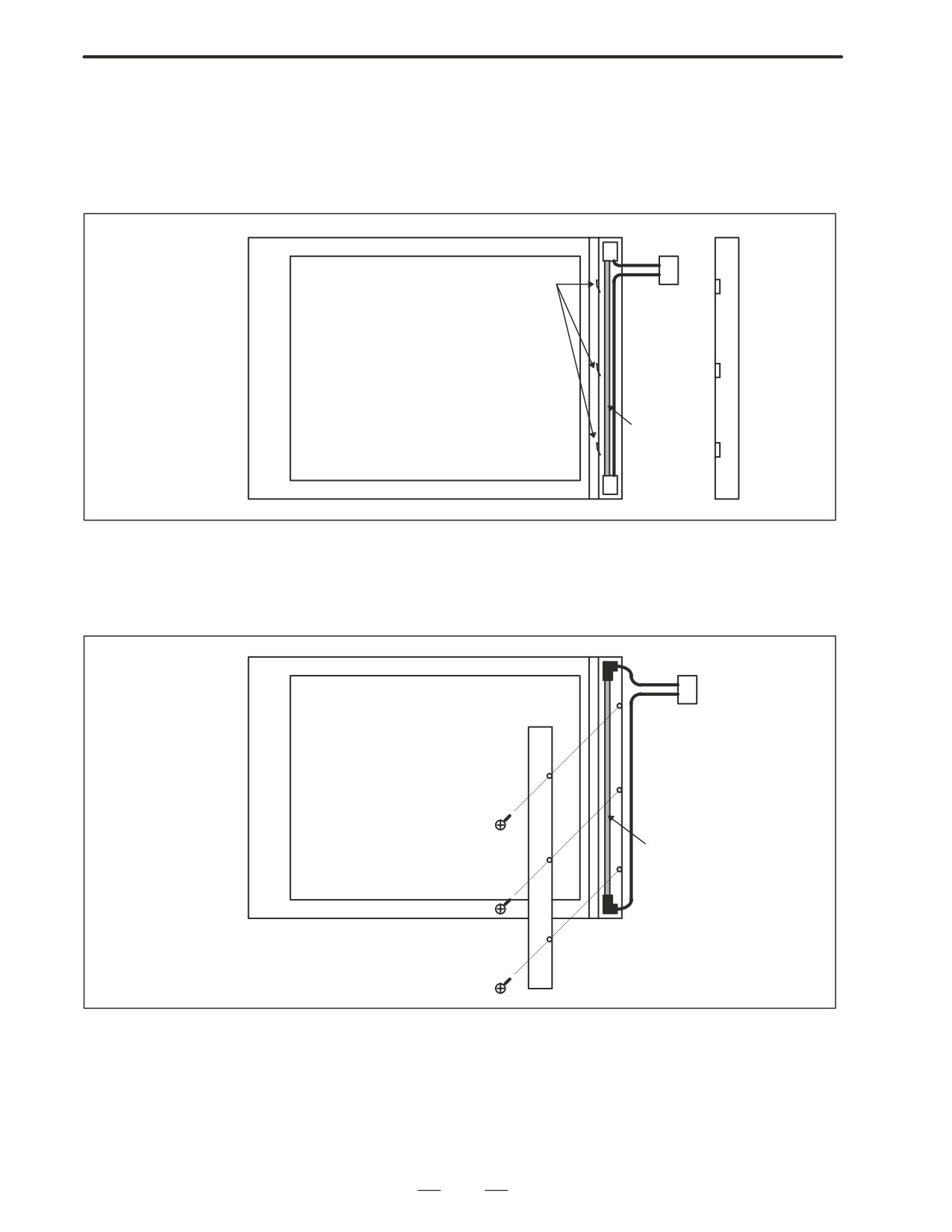
3)-3 For the 7.2” and 9.5” LCD units (monochrome) manufactured by
Hitachi
Remove the three brackets from the left part on the front of the LCD
unit, and remove the cover. Then, the backlight is exposed. Replace
the backlight with a new one.
Connector
Bracket
Display surface of LCD unit
Backlight
3)-4 For the 7.2” LCD unit (monochrome) manufactured by Sharp
Remove the three screws from the left part on the front of the LCD
unit, and remove the cover. Then, the backlight is exposed. Replace
the backlight with a new one.
Connector
Display surface of LCD unit
Backlight
4) Upon completion of replacement, reassemble the unit by reversing
the steps 1 through 3 above.
162
2. HARDWARE
B-63005EN/01
The performance of the heat exchanger degrades due to a buildup of dirt.
2.12
Clean the heat exchanger periodically. The cleaning interval depends on
MAINTENANCE OF
the installation environment. So, clean the heat exchanger at appropriate
HEAT EXCHANGER
intervals according to the level of dirt built up.
OF HEAT PIPE TYPE
WARNING
High voltage is applied to the heat exchanger of heat pipe
type. Before maintaining the heat exchanger of heat pipe
type, always turn off the power to the CNC.
When opening the cabinet and replacing a heat exchanger
of heat pipe type, be careful not to touch the high-voltage
circuits (marked
and fitted with an insulating cover).
Touching the uncovered high-voltage circuits presents an
extremely dangerous electric shock hazard.
163
2. HARDWARE
B-63005EN/01
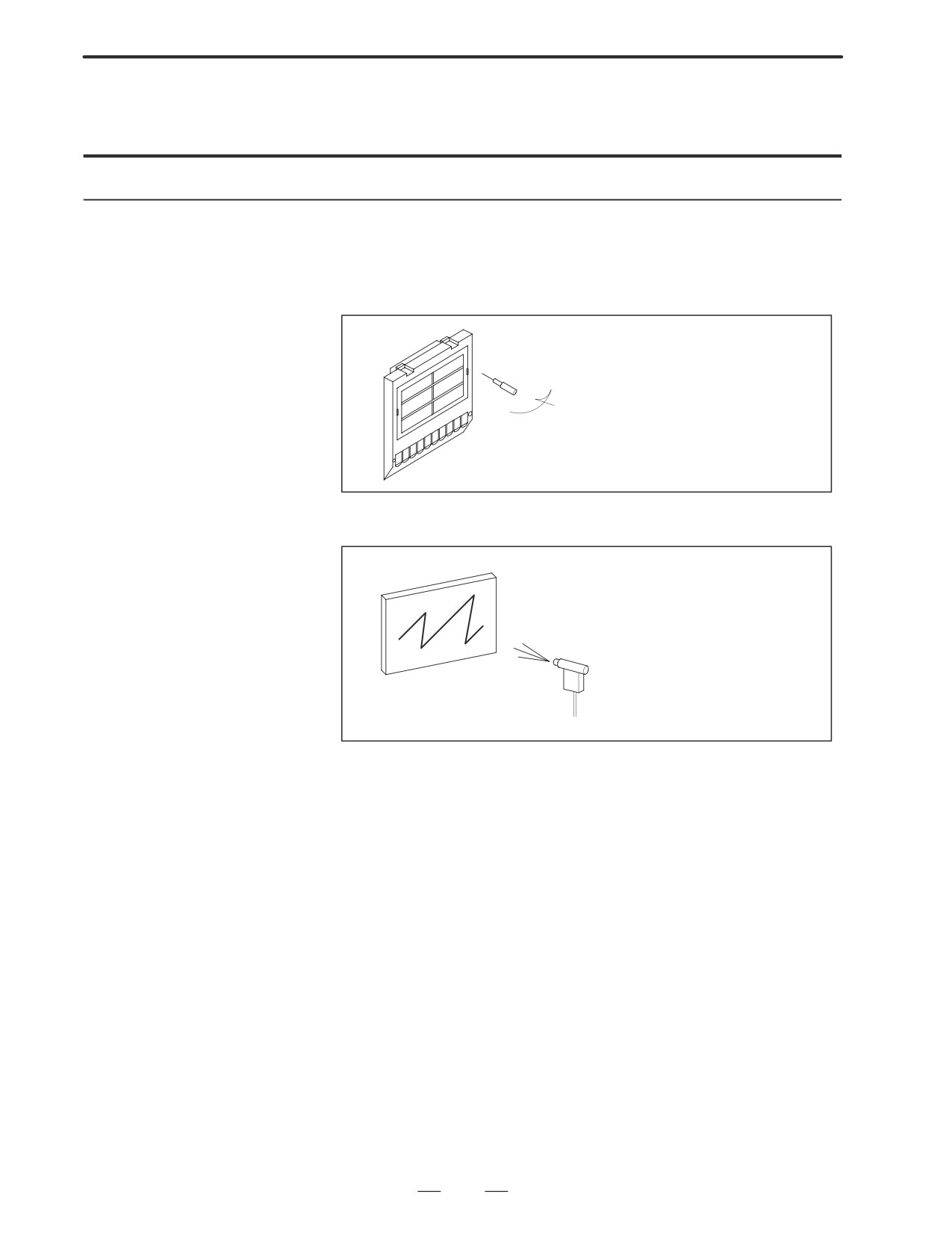
Cleaning and replacing
the air filter
Procedure for cleaning and replacing the air filter
1
Before cleaning and replacing the air filter, turn off the fan power
supply.
2
Remove the filter cover, then demount the filter.
When removing the cover, press the claw placed in
the groove on both sides inward with a screwdriver.
3. Blow air against both sides of the filter to remove dust.
4
When the filter is dirty extremely, wash it with a solution of water and
neutral detergent, and rinse it with fresh water, then allow it dry
naturally.
Alternatively, replace it with a new filter (use only the specified filter).
5
Set the cleaned or new filter. Next, align the claws with the grooves,
then press them to reinstall the cover. Check that the cover is not
removed when it is pulled toward you.
164
2. HARDWARE
B-63005EN/01
Cleaning the heat
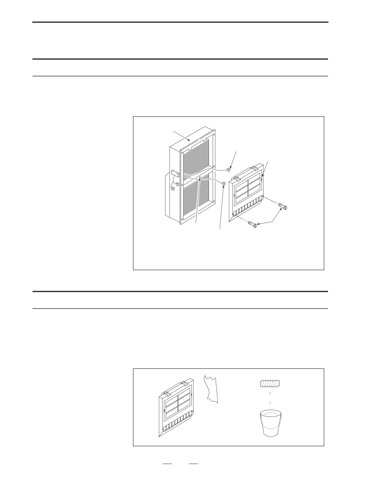
exchanger
Procedure for cleaning the heat exchanger
1
Before cleaning the heat exchanger, turn off the fan power supply.
2
Demount the external fan unit from the main body of the heat
exchanger.
Main body of the
heat exchanger
Fan power cable
(Unplug the connector.)
External fan unit
Mounting screw B (1 piece)
Mounting screw A (2 pieces)
Ground wire (The ground wire can be disconnected by
removing the fan mounting screws.)
Remove the two mounting screws (A) used for mounting the external fan unit, then
demount the unit by sliding it downward. Next, disconnect the fan power cable and
ground wire. Remove mounting screw (B).
D Cleaning the fan unit
Procedure for cleaning the fan unit
1
Remove any buildup of dust, dirt, and mist from the fan motor and fan
mounting case with a dry waste cloth. If dirt such as mist cannot be
removed easily, use a waste cloth moistened with a solution of water
and neutral detergent after squeezing it softly. In this case, be careful
not to allow a solution of water and neutral detergent to enter the
electric circuitry such as the rotor of the fan motor.
165
2. HARDWARE
B-63005EN/01
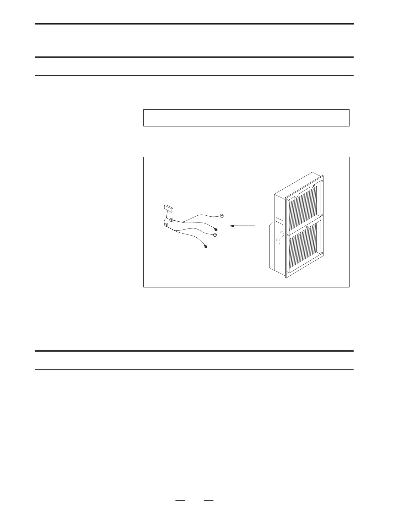
D Cleaning the fan of the
heat exchanger
Procedure for cleaning the fan of the heat exchanger
1
Demount the heat exchanger from the unit, then remove dust and mist
from the fan by blowing air or by using a dry waste cloth or brush.
When the fan is dirty extremely
1
Detach the internal fan unit, terminal block, and cables from the main
body.
Main body
Terminal block, cables
2
Clean the fan by using a brush and a solution of water and neutral
detergent. At this time, be careful not to bend a vane.
3
After cleaning, dry the heat exchanger and fan unit sufficiently.
D Reassembly
Procedure for reassembly after cleaning
After cleaning the fan unit and heat exchanger, follow the steps below.
1
Reinstall the terminal block and cables at the original locations.
2
Reinstall the fan unit at the original location. At this time, reconnect
the fan power cable and ground wire correctly.
166
2. HARDWARE
B-63005EN/01
2.13
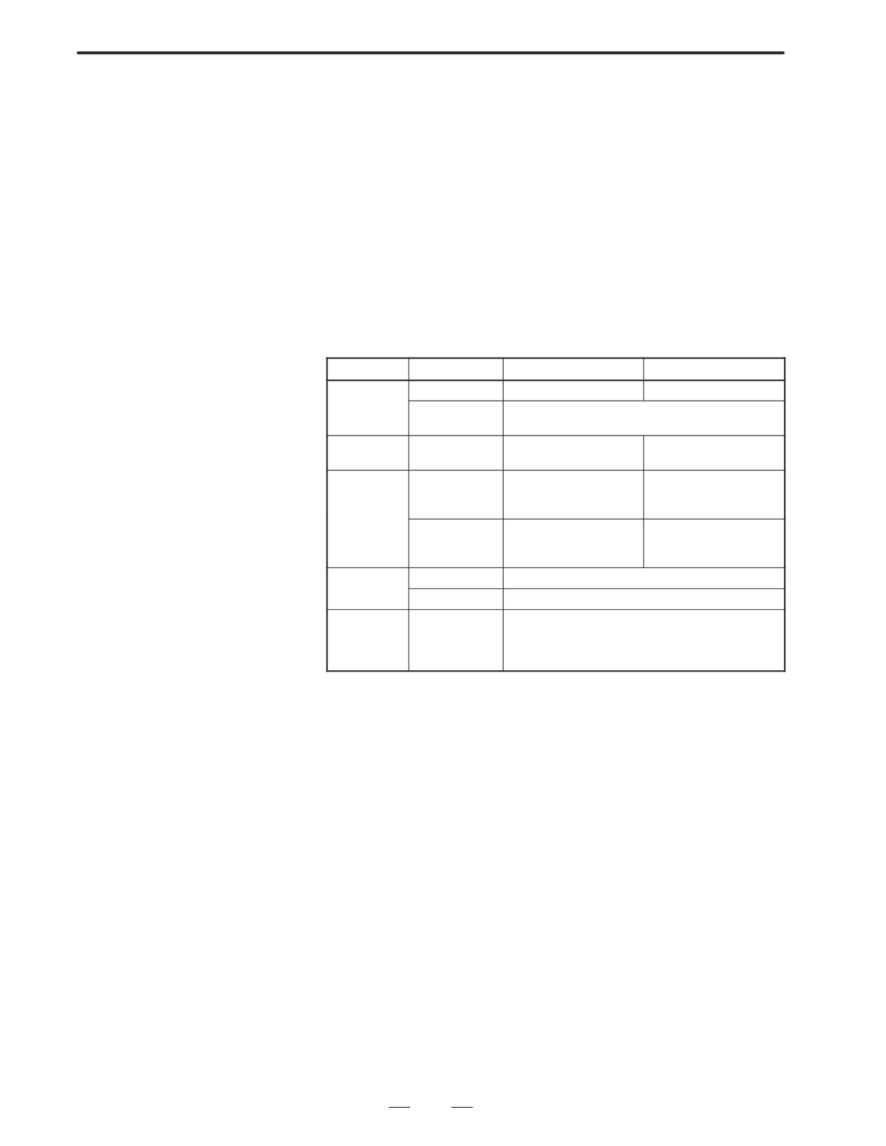
ENVIRONMENTAL
The control units and various peripheral units provided by FANUC are
CONDITIONS
designed to be accommodated in closed cabinets. Usable cabinets are as
follows:
OUTSIDE CABINET
D Cabinets manufactured by machine tool builders to accommodate a
control unit and peripheral units
D Cabinets for a flexible turnkey system provided by FANUC
D Teach pendant manufactured by machine tool builders to
accommodate an indicator, MDI unit, and operator’s panel
D Similar cabinets
These cabinets must be installed under the following environmental
conditions:
Condition
Without PC function
With PC function
Ambient tem-
Operating
0°C to 45°C
5°C to 40°C
perature
Storage, trans-
-20°C to 60°C
portation
Temperature
1.1°C/minute maximum
0.3°C/minute maximum
variation
Humidity
Usually
75% or less
10% to 75%
(relative humidity)
(relative humidity)
No condensation
No condensation
Short term
95% or less
10% to 90%
(within 1 month)
(relative humidity)
(relative humidity)
No condensation
No condensation
Vibration
Operating
0.5 G or less
Non-operating
1.0 G or less
Atmosphere
Normal machining factory environment.
(A separate
study is required when the cabinets are used in an envi-
ronment exposed to relatively high levels of dust, cool-
ant, and organic solvents.)
167
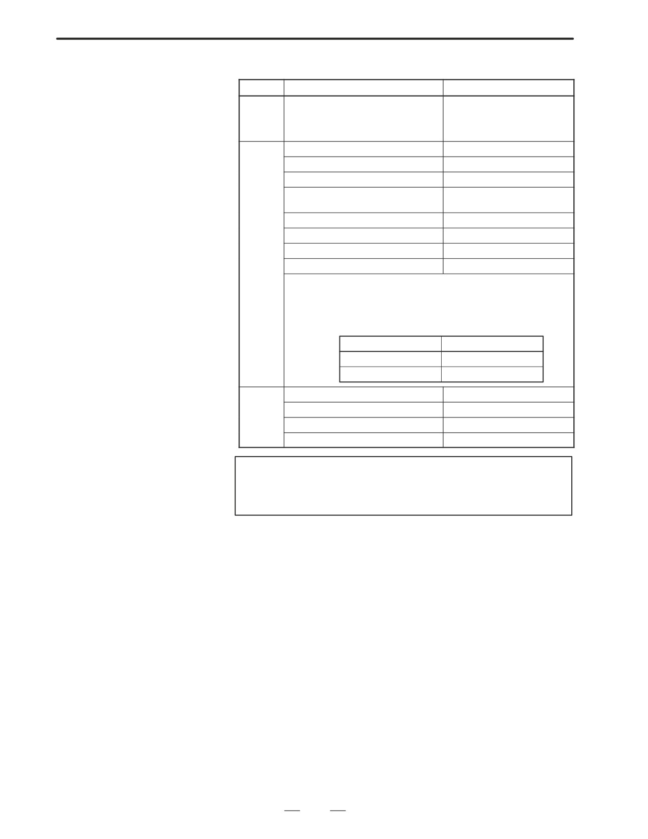
2. HARDWARE
B-63005EN/01
2.14
POWER
Name
Power consumption (W)
Basic (including an LCD unit and fans).
Without the PC function: 33
CONSUMPTION OF
(When the PC function is provided, a hard
With the PC function: 45
EACH UNIT
disk drive and floppy disk drive are in-
cluded.)
Optional
Sub-CPU board
13
board
C language board
5
Loader control board
10
Serial communication board (remote buff-
6
er/DNC2, DNC1)
Data server board
9
RISC board
9
CAP-II board
5
HSSB interface board
3
For the CNC unit, a 2-slot rack and 4-slot rack for mounting option boards are
available. From the option boards listed above, two or four boards can be se-
lected. However, ensure that the total power consumption does not exceed the
values indicated below.
Type of rack
Total power consumption
2-slot rack
26
4-slot rack
38
ISA expansion unit
(35)(NOTE)
Operator’s panel for distributed I/O
12
Distributed I/O basic unit
8
Distributed I/O basic unit
5
NOTE
The power consumption depends on the ISA expansion
board used.
168
2. HARDWARE
B-63005EN/01
The CNC is becoming increasingly smaller as the surface mount
2.15
technology and custom LSI technology advance.
COUNTERMEASURE
S AGAINST NOISE
In many cases, as the CNC becomes more compact, the mounting
locations of its constituent units become closer to a noise source in the
power magnetics cabinet.
In general, noise is generated by electrostatic coupling, electromagnetic
induction, or a grounding loop, and is induced into the CNC.
The CNC incorporates sufficient countermeasures against external noise.
However, it is difficult to measure the level and frequency of noise
quantitatively, and many unknown factors are involved. So, to improve
the operation stability of a CNC machine tool system, noise generation
must be minimized, and the induction of generated noise into the CNC
must be suppressed.
For design of equipment including a power magnetics cabinet, take these
countermeasures on the machine side against noise into consideration.
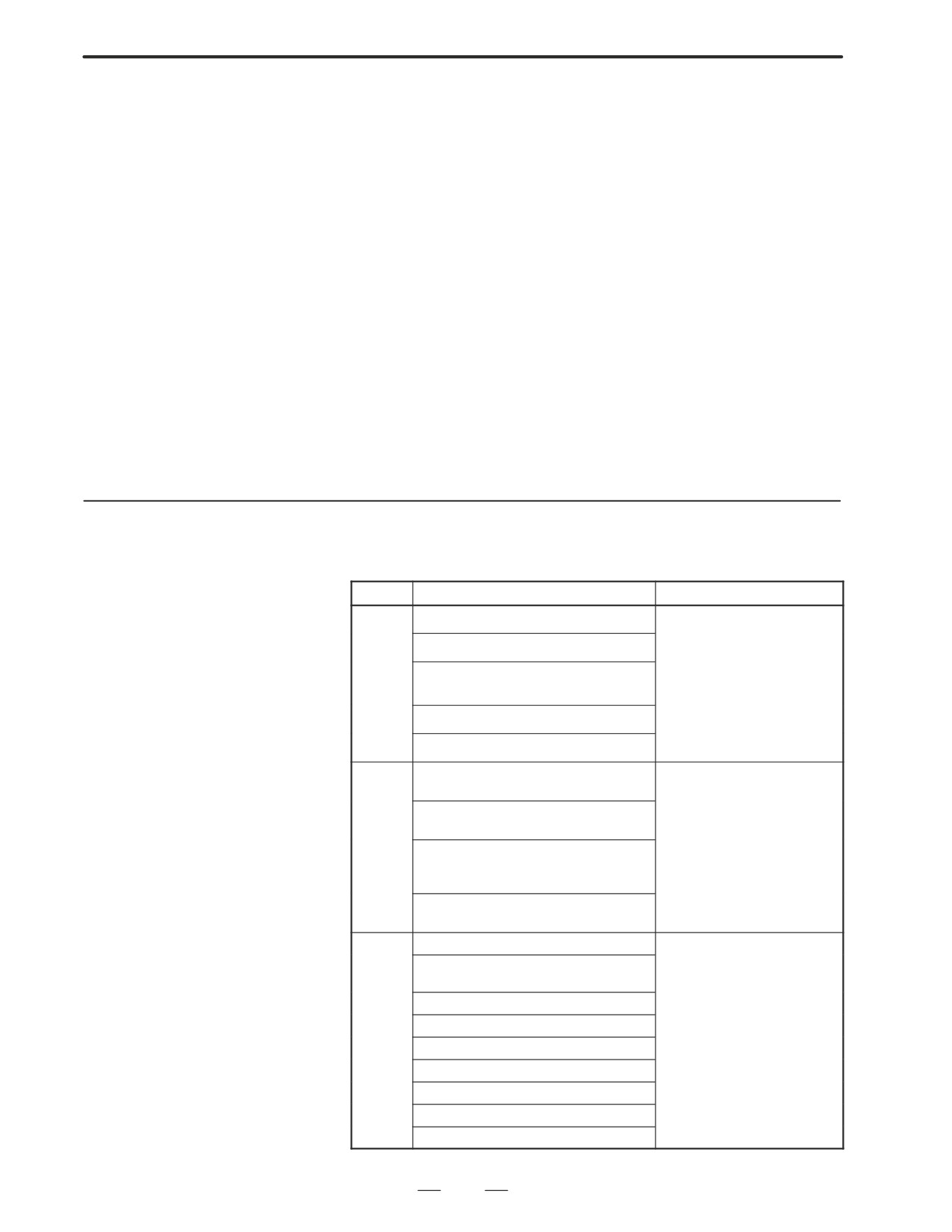
2.15.1
The cables used with a CNC machine tool are classified as indicated
below. Handle the cables of each group according to the descriptions in
Separation of Signal
the ”Action” column.
Lines
Group
Signal
Action
Primary side AC power line
Bind the cables of this group sep-
arately from the cables of groups
Secondary side AC power line
B and C(*1), or electromagneti-
cally shield the cables of this
AC/DC power lines (including servo motor
group from the cables of groups
A
and spindle motor power lines)
B and C(*2). According to the de-
scriptions of noise suppressors
AC/DC solenoid
in Section 2.15.4, attach a spark
killer or diode to the solenoid and
AC/DC relay
relay.
DC solenoid (24 VDC)
Attach a diode to the DC solenoid
and relay.
Bind the cables of this group sep-
DC relay (24 VDC)
arately from the cables of group
A, or electromagnetically shield
B
the cables of this group from the
DI-DO cable between I/O unit power mag-
cables of group A.
netics cabinets
Separate the cables of this group
from the cables of group C as far
DI-DO cable between I/O unit machines
as possible. Shielding is recom-
mended.
CNC-I/O unit cable
Bind the cables of this group sep-
arately from the cables of group
Cables for position loopback and velocity
A, or electromagnetically shield
loopback
the cables of this group from the
CNC-spindle amplifier cable
cables of group A.
Separate the cables of this group
Position coder cable
from the cables of group B as far
C
Manual pulse generator cable
as possible.
Shielding according to Section
CNC-MDI cable(*3)
2.15.5 is required.
RS-232C and RS-422 cables
Battery cable
Other cables whose shielding is specified
169