FANUC Series 0i-MODEL D, Series 0i Mate-MODEL D. PARAMETER MANUAL - page 14
B-64310EN/02
4.DESCRIPTION OF PARAMETERS
[Data type] Bit
#0 LDP The servo load meter axis display:
0: Interacts with the axis display of coordinate values.
1: Does not interact with the axis display of coordinate values.
#3 BDP When a single-block stop occurs, on the program screen and program check screen:
0: The block next to the block that has been executed is displayed at the beginning.
1: The block that has been executed is displayed at the beginning.
NOTE
Only MEM operation is enabled.
#4 DPM During MDI program execution, blocks that call an execution macro are:
0: Not displayed.
1: Displayed.
#5 ISQ During MDI editing, automatic sequence number insertion is:
0: Disabled.
1: Enabled.
11307
Display sequence of the coordinates in current position display
NOTE
When this parameter is set, the power must be turned off before
operation is continued.
[Input type] Parameter input
[Data type] Byte path
[Valid data range] 0 to 5
This parameter sets the display sequence of the coordinates of a position displayed on the
following screens:
10.4- inch display units
• Total position display screen
• Total position display on each screen
8.4-inch display units
• Total position display screen
The display sequence of coordinates corresponds to the parameter setting as follows:
Display sequence of
coordinates
1
2
3
4
Setting
Relative
Absolute
Machine
Remaining
0
coordinates
coordinates
coordinates
travel distance
Relative
Machine
Absolute
Remaining
1
coordinates
coordinates
coordinates
travel distance
Relative
Remaining
Absolute
Machine
2
coordinates
travel distance
coordinates
coordinates
Absolute
Machine
Relative
Remaining
3
coordinates
coordinates
coordinates
travel distance
Absolute
Remaining
Relative
Machine
4
coordinates
travel distance
coordinates
coordinates
Machine
Remaining
Relative
Absolute
5
coordinates
travel distance
coordinates
coordinates
If the setting is beyond the valid data range, 0 is assumed.
- 383 -
4.DESCRIPTION OF PARAMETERS
B-64310EN/02
#7
#6
#5
#4
#3
#2
#1
#0
DGH
ABH
SPH
PGS
DOP
11308
DGH
ABH
SPH
PGS
[Input type] parameter input
[Data type] Bit
#0 DOP If an alarm is issued in a path not being displayed:
0: The screen display does not change to the alarm screen.
1: The screen display changes to the alarm screen.
#4 PGS In program search operation:
0: A specified program name is searched for.
1: An O number program is searched for with "O" omitted.
#5 SPH When the spindle speed data are read with FOCAS2 or the PMC window:
0: Data that has been updated at conventional intervals (approximately 32 ms) is read.
1: Data that has been updated at short intervals is read.
NOTE
When quick response is not required in particular for display
operation and so on, normally set this parameter to 0 to reduce the
load on the CNC.
#6 ABH When the absolute coordinates data are read with FOCAS2 or the PMC window:
0: Data that has been updated at conventional intervals (approximately 32 ms) is read.
1: Data that has been updated at short intervals is read.
NOTE
When quick response is not required in particular for display
operation and so on, normally set this parameter to 0 to reduce the
load on the CNC.
#7 DGH When the Remaining travel distance data are read with FOCAS2 or the PMC window:
0: Data that has been updated at conventional intervals (approximately 32 ms) is read.
1: Data that has been updated at short intervals is read.
NOTE
When quick response is not required in particular for display
operation and so on, normally set this parameter to 0 to reduce the
load on the CNC.
11309
Menu number selected on the pattern menu screen
[Input type] Parameter input
[Data type] Byte path
[Valid data range] -128 to 127
This parameter displays the menu number selected on the pattern menu screen.
This value is the same as that of system variable #5900.
- 384 -
B-64310EN/02
4.DESCRIPTION OF PARAMETERS
#7
#6
#5
#4
#3
#2
#1
#0
11313
EMPx
[Input type] Parameter input
[Data type] Bit axis
#7 EMPx In FOCAS2 and PMC window, the machine coordinate which acceleration/deceleration
delay and servo delay are considered:
0: cannot be read. (0 is read as a machine coordinate.)
1: can be read.
#7
#6
#5
#4
#3
#2
#1
#0
RTC
DFM
11318
RTC
LSO
DFM
[Input type] Parameter input
[Data type] Bit
#2
DFM On the program list screen, of the soft key character strings when devices are selected and
selected device name character strings, the character strings related to the memory card
are:
0: Not changed.
1: Changed.
Soft key character strings when devices are selected
(10.4-inch display unit)
DFM=0
DFM=1
Mode
Name
Name
EDIT
M CARD
EDIT
MEMCARD
Other than EDIT
M CARD
OPER.
EDIT
M CARD
MEMORY
I/O
Other than EDIT
CARD
M CARD
DNC
Soft key character strings when devices are selected
(8.4-inch display unit)
DFM=0
DFM=1
Mode
Name
Name
EDIT
MC-EDT
MEMCARD
Other than EDIT
MC-OP.
EDIT
MC-I/O
M-CARD
Other than EDIT
MC-DNC
Selected device name character strings
DFM=0
DFM=1
MEMCARD
MC-PROG
M_CARD
MC-FILE
#5
LSO When level is selected on precision level select screen or
machining
quality
level
adjustment screen:
0: Soft key and MDI key can be used.
1: Only soft key can be used.
- 385 -
4.DESCRIPTION OF PARAMETERS
B-64310EN/02
#6 RTC On the program list screen, a file selected by a selection operation:
0: Can be copied repeatedly.
1: Cannot be copied repeatedly.
#7
#6
#5
#4
#3
#2
#1
#0
11320
DHN
[Data type] Bit path
#0 DHN On the program check screen, HD.T and NX.T, and a T number are:
0: Not displayed at the same time.
1: Displayed at the same time.
If DHN is set to 1, HD.T, NX.T, and T are displayed regardless of the setting of
parameter PCT(No. 3108#2).
11321
Spindle tool name (1st character)
11322
Spindle tool name (2nd character)
11323
Spindle tool name (3rd character)
11324
Spindle tool name (4th character)
[Input type] Parameter input
[Data type] Byte path
[Valid data range] See the character-code correspondence table.
The name of the spindle tool (HD.T) displayed on the program check screen can be
changed.
Any character string consisting of numeric characters, alphabetical characters, katakana
characters, and symbols with a maximum length of four characters can be displayed.
NOTE
For characters and codes, see Appendix A, "CHARACTER-CODE
CORRESPONDENCE TABLE".
If the first character is 0 or an illegal character code, "HD.T" is
displayed.
11325
Next machining tool name (1st character)
11326
Next machining tool name (2nd character)
11327
Next machining tool name (3rd character)
11328
Next machining tool name (4th character)
[Input type] Parameter input
[Data type] Byte path
[Valid data range] See the character-code correspondence table.
The name of the next machining tool (NX.T) displayed on the program check screen can
be changed.
Any character string consisting of numeric characters, alphabetical characters, katakana
characters, and symbols with a maximum length of four characters can be displayed.
- 386 -

B-64310EN/02
4.DESCRIPTION OF PARAMETERS
NOTE
For characters and codes, see Appendix A, "CHARACTER-CODE
CORRESPONDENCE TABLE".
If the first character is 0 or an illegal character code, "NX.T" is
displayed.
4.70 PARAMETERS OF GRAPHIC DISPLAY (2 OF 3)
#7
#6
#5
#4
#3
#2
#1
#0
11329
GST
ACT
AER
GTF
BGM
GTL
DPC
[Input type] Parameter input
[Data type] Bit path
#1 DPC The current coordinates displayed on each screen of the dynamic graphic display function
are:
0: Absolute coordinates.
1: Machine coordinates.
#2 GTL When animated simulation is performed with the dynamic graphic display function,
drawing at positions with tool length compensation considered is:
0: Not performed.
1: Performed.
#3 BGM Coordinates used by the dynamic graphic display function are:
0: Absolute coordinates.
1: Machine coordinates.
#4 GTF In tool path drawing with the dynamic graphic display function, drawing at in a position
where tool compensation (tool length compensation, cutter compensation) is considered
is:
0: Performed.
1: Not performed.
#5 AER When the tool path is drawn with the dynamic graphic display function, automatic erasure
at the start of drawing is:
0: Not performed.
1: Performed.
#6 ACT In tool path drawing with the dynamic graphic display function, the drawing color of a
tool path is:
0: Not changed automatically.
1: Changed automatically.
#7 GST When drawing cannot be performed for a command with the dynamic graphic display
function:
0: The command is ignored, and drawing continues without stopping drawing.
1: Drawing stops.
- 387 -
4.DESCRIPTION OF PARAMETERS
B-64310EN/02
11330
Magnification of drawing in dynamic graphic display
[Input type] Parameter input
[Data type] Word path
[Unit of data] 0.01
[Valid data range] 1 to 10000
This parameter sets the magnification of the drawing range in the dynamic graphic
display function.
11331
Screen center coordinate value in the drawing range in dynamic graphic display
[Input type] Parameter input
[Data type] Real axis
[Unit of data] mm,inch (input unit)
[Min. unit of data] Depend on the increment system of the applied axis
[Valid data range] 9 digit of minimum unit of data (refer to standard parameter setting table (A))
(When the increment system is IS-B, -999999.999 to +999999.999)
This parameter sets the coordinate value of the center of the drawing range in the
dynamic graphic display function.
NOTE
If bit 3 (BGM) of parameter No. 11329 is set to 1, set the coordinate
value on each axis in the machine coordinate system.
11332
Drawing range of tool path drawing in dynamic graphic display (maximum value)
[Input type] Parameter input
[Data type] Real axis
[Unit of data] mm,inch (input unit)
[Min. unit of data] Depend on the increment system of the applied axis
[Valid data range] 9 digit of minimum unit of data (refer to standard parameter setting table (A))
(When the increment system is IS-B, -999999.999 to +999999.999)
This parameter sets the maximum coordinates in the drawing range in tool path drawing
with dynamic graphic display function.
11333
Drawing range of tool path drawing in dynamic graphic display (minimum value)
[Input type] Parameter input
[Data type] Real axis
[Unit of data] mm,inch (input unit)
[Min. unit of data] Depend on the increment system of the applied axis
[Valid data range] 9 digit of minimum unit of data (refer to standard parameter setting table (A))
(When the increment system is IS-B, -999999.999 to +999999.999)
This parameter sets the minimum coordinates in the drawing range in tool path drawing
with dynamic graphic display function.
11334
Rotation angle of the drawing coordinate system in dynamic graphic display (vertical direction)
[Input type] Parameter input
- 388 -
B-64310EN/02
4.DESCRIPTION OF PARAMETERS
[Data type] Word path
[Unit of data] degree
[Valid data range] -360 to 360
This parameter sets the rotation angle (vertical direction) of the drawing coordinate
system in the dynamic graphic display function.
11335
Rotation angle of the drawing coordinate system in dynamic graphic display (horizontal direction)
[Input type] Parameter input
[Data type] Word path
[Unit of data] degree
[Valid data range] -360 to 360
This parameter sets the rotation angle of the drawing coordinate system in the dynamic
graphic display function (the angle of rotation about the vertical axis on the screen, that
passes the center position of the blank).
11336
Drawing color of the tool path in tool path drawing in dynamic graphic display
[Input type] Parameter input
[Data type] Byte path
[Valid data range] 0 to 6
This parameter sets the color in which the tool path is drawn with the dynamic graphic
display function.
11337
Color of the cursor indicating the tool position on the PATH GRAPHIC (TOOL POSITION) screen of
dynamic graphic display
[Input type] Parameter input
[Data type] Byte path
[Valid data range] 0 to 6
This parameter sets the color of the cursor indicating the tool position on the PATH
GRAPHIC (TOOL POSITION) screen of the dynamic graphic display function.
11339
Drawing start sequence number in dynamic graphic display
[Input type] Parameter input
[Data type] 2-word path
[Valid data range] 0 to 99999
This parameter sets the sequence number at which drawing is started by the dynamic
graphic display function.
11340
Drawing end sequence number in dynamic graphic display
[Input type] Parameter input
[Data type] 2-word path
[Valid data range] 0 to 99999
This parameter sets the sequence number at which drawing is ended by the dynamic
graphic display function.
- 389 -
4.DESCRIPTION OF PARAMETERS
B-64310EN/02
11341
Drawing color of a blank figure in dynamic graphic display
[Input type] Parameter input
[Data type] Byte path
[Valid data range] 0 to 6
This parameter sets the color in which a blank figure is drawn with the dynamic graphic
display function.
11342
Rotation angle of the drawing coordinate system of dynamic graphic display (screen center)
[Input type] Parameter input
[Data type] Word path
[Unit of data] degree
[Valid data range] -360 to 360
This parameter sets the rotation angle of the drawing coordinate system in dynamic
graphic display function (the angle of rotation about the vertical axis on the screen plane,
that passes the center position of the blank).
11343
Blank figure in dynamic graphic display
[Input type] Parameter input
[Data type] Byte path
[Valid data range] 0 to 1
This parameter sets the type of a blank figure in dynamic graphic display function.
Setting
Figure
0
Cylinder or hollow cylinder (parallel to the Z-axis)
1
Rectangular parallelepiped
11344
Blank reference position in dynamic graphic display
[Input type] Parameter input
[Data type] Real axis
[Unit of data] mm,inch (input unit)
[Min. unit of data] Depend on the increment system of the applied axis
[Valid data range] 9 digit of minimum unit of data (refer to standard parameter setting table (A))
(When the increment system is IS-B, -999999.999 to +999999.999)
This parameter sets the reference position of a blank in the dynamic graphic display
function by using coordinate values in the workpiece coordinate system.
NOTE
If bit 3 (BGM) of parameter No. 11329 is set to 1, set coordinate
values in the machine coordinate system.
11345
Blank dimension I in dynamic graphic display
11346
Blank dimension J in dynamic graphic display
- 390 -
B-64310EN/02
4.DESCRIPTION OF PARAMETERS
11347
Blank dimension K in dynamic graphic display
[Input type] Parameter input
[Data type] Real axis
[Unit of data] mm,inch (input unit)
[Min. unit of data] Depend on the increment system of the reference axis
[Valid data range] 0 or positive 9 digit of minimum unit of data (refer to the standard parameter setting table
(B))
(When the increment system is IS-B, 0.000 to +999999.999)
These parameters set the dimensions of a blank in the dynamic graphic display function
according to the blank figure as follows:
Blank figure
Address I
Address J
Address K
Rectangular
Length in the X-axis
Length in the Y-axis
Length in the Z-axis
parallelepiped
direction
direction
direction
Cylinder
Radius of a cylinder
0
Length of a cylinder
Barrel
Radius of the outer
Radius of the inner
Length of a barrel
circle of a barrel
circle of a barrel
11348
Drawing color of a tool in animated simulation in dynamic graphic display
[Input type] Parameter input
[Data type] Byte path
[Valid data range] 0 to 6
This parameter sets the color in which a tool is drawn during animated simulation in the
dynamic graphic display function.
#7
#6
#5
#4
#3
#2
#1
#0
PDM
11349
PDM
GSP
ABC
[Input type] Parameter input
[Data type] Bit
#1 ABC In animated simulation in the dynamic graphic display function, when a fine boring cycle
or back boring cycle, which is a hole machining canned cycle, is performed, the
movement for a shift at the hole bottom is:
0: Not drawn.
1: Drawn.
#2 GSP In tool path drawing in the dynamic graphic display function, the drawing start position
is:
0: The end position of a block that makes a movement for the first time.
1: The current position.
NOTE
When G92, G52, or G92.1 is specified at the beginning of a
program to be drawn, the position specified in this G code is
assumed to be the drawing start position.
- 391 -
4.DESCRIPTION OF PARAMETERS
B-64310EN/02
#7 PDM When the pattern data input function is enabled (bit 7 (NPD) of parameter No. 8135 is 0),
displaying of the variable name and comment on the custom macro screen is:
0: Performed only during menu selection.
1: Always performed.
4.71 PARAMETERS OF DISPLAY AND EDIT (3 OF 5)
#7
#6
#5
#4
#3
#2
#1
#0
PAD
9DE
11350
QLS
PAD
9DE
[Input type] Parameter input
[Data type] Bit
NOTE
When this parameter is set, the power must be turned off before
operation is continued.
#4
9DE The number of axes that can be displayed on one screen of the 8.4-inch monitor is:
0: Up to 4.
1: Up to 5.
#5 PAD On the pitch error compensation screen, axis names are:
0: Not displayed.
1: Displayed.
#6 QLS The machining quality level adjustment screen is:
0: Not displayed.
1: Displayed.
#7
#6
#5
#4
#3
#2
#1
#0
11353
SEK
[Input type] Parameter input
[Data type] Bit
#0 SEK When the power is turned on, or when the clear state is present, sequence numbers are:
0: Not maintained.
1: Maintained.
NOTE
During a subprogram call, the sequence number of the subprogram
is maintained.
11363
Radius of a tool figure in dynamic graphic display
[Input type] Parameter input
[Data type] Real axis
[Unit of data] mm,inch (input unit)
[Min. unit of data] Depend on the increment system of the reference axis
- 392 -
B-64310EN/02
4.DESCRIPTION OF PARAMETERS
[Valid data range] 0 or positive 9 digit of minimum unit of data (refer to the standard parameter setting table
(B))
(When the increment system is IS-B, 0.000 to +999999.999)
This parameter sets the radius of a tool figure in animated simulation with the dynamic
graphic display function.
4.72 PARAMETERS OF TOOL COMPENSATION (2 OF 3)
#7
#6
#5
#4
#3
#2
#1
#0
M8D
11400
[Input type] Parameter input
[Data type] Bit path
#0 M8D The number of digits of a T code used to change tool compensation automatically is:
0:
4.
(Existing DI signals G68 and G69 are used.)
1:
8.
(DI signals G525 to G528 are used.)
4.73 PARAMETERS OF RIGID TAPPING (2 OF 2)
#7
#6
#5
#4
#3
#2
#1
#0
11420
RAU
[Input type] Parameter input
[Data type] Bit path
#0 RAU The rigid tapping optimum acceleration/deceleration function is:
0: Disabled.
1: Enabled.
11421
Maximum acceleration of rigid tapping optimum acceleration/deceleration (1st gear)
11422
Maximum acceleration of rigid tapping optimum acceleration/deceleration (2nd gear)
11423
Maximum acceleration of rigid tapping optimum acceleration/deceleration (3rd gear)
Maximum acceleration of rigid tapping optimum acceleration/deceleration (4th gear)
11424
[Input type] Parameter input
[Data type] 2-word spindle
[Unit of data] rev/sec2
[Valid data range] 0 to 10000.0
This parameter sets the maximum acceleration.
11425
Acceleration change time of bell-shaped acceleration/deceleration in rigid tapping optimum
acceleration/deceleration (1st gear)
11426
Acceleration change time of bell-shaped acceleration/deceleration in rigid tapping optimum
acceleration/deceleration (2nd gear)
- 393 -
4.DESCRIPTION OF PARAMETERS
B-64310EN/02
11427
Acceleration change time of bell-shaped acceleration/deceleration in rigid tapping optimum
acceleration/deceleration (3rd gear)
[Input type] Parameter input
[Data type] Word spindle
[Unit of data] msec
[Valid data range] 0~200
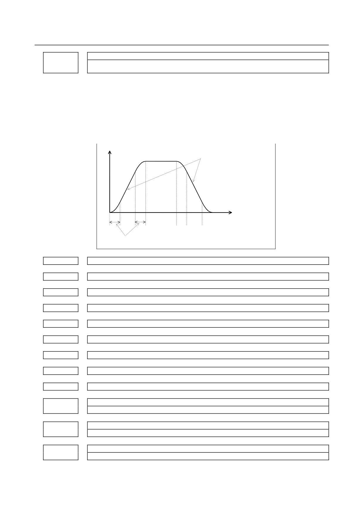
This parameter sets the acceleration change time (time required to change from constant
speed state (A) to acceleration/deceleration state (C) at the acceleration calculated from
rigid tapping optimum acceleration/deceleration (indicated by (B) below)) of bell-shaped
acceleration/deceleration in rigid tapping optimum acceleration/deceleration.
Speed min-1
The maximum acceleration within the
maximum allowable acceleration is
calculated automatically.
(A)
(B)
(C)
(B)
(A)
(B)
(C)
(B)
(A)
Acceleration change time
11429
P1 spindle speed of rigid tapping optimum acceleration/deceleration (1st gear)
11430
P2 spindle speed of rigid tapping optimum acceleration/deceleration (1st gear)
11431
P3 spindle speed of rigid tapping optimum acceleration/deceleration (1st gear)
11432
P1 spindle speed of rigid tapping optimum acceleration/deceleration (2nd gear)
11433
P2 spindle speed of rigid tapping optimum acceleration/deceleration (2nd gear)
11434
P3 spindle speed of rigid tapping optimum acceleration/deceleration (2nd gear)
11435
P1 spindle speed of rigid tapping optimum acceleration/deceleration (3rd gear)
11436
P2 spindle speed of rigid tapping optimum acceleration/deceleration (3rd gear)
11437
P3 spindle speed of rigid tapping optimum acceleration/deceleration (3rd gear)
P1 spindle speed of rigid tapping optimum acceleration/deceleration (4th gear)
11438
P2 spindle speed of rigid tapping optimum acceleration/deceleration (4th gear)
11439
P3 spindle speed of rigid tapping optimum acceleration/deceleration (4th gear)
11440
[Input type] Parameter input
- 394 -
B-64310EN/02
4.DESCRIPTION OF PARAMETERS
[Data type] Byte spindle
[Unit of data] %
[Valid data range] 0 to 100
This parameter sets the ratio of the spindle speed at acceleration setting points P1 to P3 of
P0 to P4 to the maximum spindle speed (parameters Nos. 5241 to 5244). The spindle
speed at P0 is 0 and the spindle
speed at P4 is the maximum spindle speed.
The
acceleration setting point at which 0 is set is skipped.
11441
P0 allowable acceleration of rigid tapping optimum acceleration/deceleration (1st gear)
11442
P1 allowable acceleration of rigid tapping optimum acceleration/deceleration (1st gear)
11443
P2 allowable acceleration of rigid tapping optimum acceleration/deceleration (1st gear)
11444
P3 allowable acceleration of rigid tapping optimum acceleration/deceleration (1st gear)
11445
P4 allowable acceleration of rigid tapping optimum acceleration/deceleration (1st gear)
11446
P0 allowable acceleration of rigid tapping optimum acceleration/deceleration (2nd gear)
11447
P1 allowable acceleration of rigid tapping optimum acceleration/deceleration (2nd gear)
11448
P2 allowable acceleration of rigid tapping optimum acceleration/deceleration (2nd gear)
11449
P3 allowable acceleration of rigid tapping optimum acceleration/deceleration (2nd gear)
11450
P4 allowable acceleration of rigid tapping optimum acceleration/deceleration (2nd gear)
11451
P0 allowable acceleration of rigid tapping optimum acceleration/deceleration (3rd gear)
11452
P1 allowable acceleration of rigid tapping optimum acceleration/deceleration (3rd gear)
11453
P2 allowable acceleration of rigid tapping optimum acceleration/deceleration (3rd gear)
11454
P3 allowable acceleration of rigid tapping optimum acceleration/deceleration (3rd gear)
11455
P4 allowable acceleration of rigid tapping optimum acceleration/deceleration (3rd gear)
P0 allowable acceleration of rigid tapping optimum acceleration/deceleration (4th gear)
11456
P1 allowable acceleration of rigid tapping optimum acceleration/deceleration (4th gear)
11457
P2 allowable acceleration of rigid tapping optimum acceleration/deceleration (4th gear)
11458
P3 allowable acceleration of rigid tapping optimum acceleration/deceleration (4th gear)
11459
P4 allowable acceleration of rigid tapping optimum acceleration/deceleration (4th gear)
11460
[Input type] Parameter input
[Data type] Byte spindle
- 395 -
4.DESCRIPTION OF PARAMETERS
B-64310EN/02
[Unit of data] %
[Valid data range] 0 to 100
This parameter sets the ratio of the allowable acceleration at acceleration setting points P0
to P4 to the maximum acceleration (parameters Nos. 11421 to 11424). The rate of the
acceleration setting point at which 0 is set is assumed to be 100%.
11461
P0 allowable deceleration of rigid tapping optimum acceleration/deceleration (1st gear)
11462
P1 allowable deceleration of rigid tapping optimum acceleration/deceleration (1st gear)
11463
P2 allowable deceleration of rigid tapping optimum acceleration/deceleration (1st gear)
11464
P3 allowable deceleration of rigid tapping optimum acceleration/deceleration (1st gear)
11465
P4 allowable deceleration of rigid tapping optimum acceleration/deceleration (1st gear)
11466
P0 allowable deceleration of rigid tapping optimum acceleration/deceleration (2nd gear)
11467
P1 allowable deceleration of rigid tapping optimum acceleration/deceleration (2nd gear)
11468
P2 allowable deceleration of rigid tapping optimum acceleration/deceleration (2nd gear)
11469
P3 allowable deceleration of rigid tapping optimum acceleration/deceleration (2nd gear)
11470
P4 allowable deceleration of rigid tapping optimum acceleration/deceleration (2nd gear)
11471
P0 allowable deceleration of rigid tapping optimum acceleration/deceleration (3rd gear)
11472
P1 allowable deceleration of rigid tapping optimum acceleration/deceleration (3rd gear)
11473
P2 allowable deceleration of rigid tapping optimum acceleration/deceleration (3rd gear)
11474
P3 allowable deceleration of rigid tapping optimum acceleration/deceleration (3rd gear)
11475
P4 allowable deceleration of rigid tapping optimum acceleration/deceleration (3rd gear)
P0 allowable deceleration of rigid tapping optimum acceleration/deceleration (4th gear)
11476
P1 allowable deceleration of rigid tapping optimum acceleration/deceleration (4th gear)
11477
P2 allowable deceleration of rigid tapping optimum acceleration/deceleration (4th gear)
11478
P3 allowable deceleration of rigid tapping optimum acceleration/deceleration (4th gear)
11479
P4 allowable deceleration of rigid tapping optimum acceleration/deceleration (4th gear)
11480
[Input type] Parameter input
[Data type] Byte spindle
[Unit of data] %
- 396 -
B-64310EN/02
4.DESCRIPTION OF PARAMETERS
[Valid data range] 0 to 100
This parameter sets the ratio of the allowable deceleration at acceleration setting points
P0 to P4 to the maximum acceleration (parameters Nos. 11421 to 11424). The rate of
the acceleration setting point at which 0 is set is assumed to be 100%.
4.74 PARAMETERS OF PROGRAMS (2 OF 3)
#7
#6
#5
#4
#3
#2
#1
#0
11500
RS2
[Input type] Parameter input
[Data type] Bit
#5 RS2 When CS/RS of the communication cable for the RS-232-C crosses :
0: Communication is ended after checking the CS signal.
1: Communication is ended without checking the CS signal.
4.75 PARAMETERS OF DISPLAY AND EDIT (4 OF 5)
11528
Spindle name (1st character)
11529
Spindle name (2nd character)
[Input type] Parameter input
[Data type] Word spindle
[Valid data range] See the character-code correspondence table.
The codes of numbers, alphanumeric characters, and special characters displayed as
spindle name (Sxx) in the spindle setting screen, the spindle tuning screen, and the
spindle monitor screen is set.
When it is the following, the spindle name (Sxx) is displayed according to the table
below.
• When "0" is set in parameter No.11528
• When an illegal code is set in parameter No.11528 or No.11529
Spindle name
Spindle setting
Spindle setting
screen
Spindle tuning
Spindle monitor
screen
(machine
screen
screen
(parameters)
constants)
Path1
S11
S11
S11
S11
1st spindle
Path1
S21
S21
S21
S21
2nd spindle
Path2
S11
S11
S11
S11
1st spindle
Path2
S21
S21
S21
S21
2nd spindle
- 397 -
4.DESCRIPTION OF PARAMETERS
B-64310EN/02
4.76 PARAMETERS OF PROGRAMS (3 OF 3)
#7
#6
#5
#4
#3
#2
#1
#0
11602
NCP
[Data type] Bit path
#5 NCP If there is a non-threading block between two threading blocks, the second threading
block:
0: Waits until the spindle one-rotation signal and the spindle speed arrival signal (SAR)
are detected.
1: Does not wait until the spindle one-rotation signal and the spindle speed arrival
signal (SAR) are detected unless a G code in non-threading group 01 is issued.
(FS0i-C-compatible specification)
#7
#6
#5
#4
#3
#2
#1
#0
MDE
11630
MDE
FRD
[Input type] Parameter input
[Data type] Bit path
#0 FRD The minimum command unit of the rotation angles of coordinate rotation is:
0:
0.001 degree.
1:
0.00001 degree. (1/100,000)
#1 MDE An external device subprogram call (M198 command) in the MDI mode is:
0: Disabled.
1: Enabled.
4.77 PARAMETERS OF MACHINING QUALITY LEVEL
ADJUSTMENT (M SERIES)
11681
Smoothing level currently selected when Nano smoothing is used
[Input type] Parameter input
[Data type] Byte path
[Valid data range] 1 to 10
This parameter sets the smoothing level currently selected when Nano smoothing is used.
11682
Tolerance when Nano smoothing is used (smoothing level 1)
11683
Tolerance when Nano smoothing is used (smoothing level 10)
[Input type] Parameter input
[Data type] Real path
[Unit of data] mm, inch, degree (input unit)
[Min. unit of data] Depend on the increment system of the reference axis
[Valid data range] 0 or positive 9 digit of minimum unit of data (refer to the standard parameter setting table
(B))
- 398 -
B-64310EN/02
4.DESCRIPTION OF PARAMETERS
Each of these parameters sets a tolerance value when Nano smoothing is used.
It is necessary to set the value of both level 1 and level 10.
11686
Standard value of smoothing level when Nano smoothing is used
[Input type] Parameter input
[Data type] Byte path
[Valid data range] 0 to 10
Set standard value of smoothing level when Nano smoothing is used.
When the power is turned on or the system is reset, the smoothing level
0
: keeps its value.
1 to 10 : becomes the level set to this parameter.
11687
Standard value of precision level when AI contour control II is used
[Input type] Parameter input
[Data type] Byte path
[Valid data range] 0 to 10
Set standard value of precision level when AI contour control II is used.
When the power is turned on or the system is reset, the precision level
0
: keeps its value.
1 to 10 : becomes the level set to this parameter.
4.78 PARAMETERS OF SERVO (2 OF 2)
#7
#6
#5
#4
#3
#2
#1
#0
11802
KSV
[Input type] Parameter input
[Data type] Bit axis
NOTE
When this parameter is set, the power must be turned off before
operation is continued.
#4 KSV Servo axis is:
0: Enabled.
1: Disabled.
NOTE
1 This setting is effective regardless of the value of parameter
No.1023.
2 If this setting is made for the axis subject to Cs axis contour/spindle
positioning, Cs axis contour/spindle positioning will be disabled.
- 399 -
4.DESCRIPTION OF PARAMETERS
B-64310EN/02
4.79 PARAMETERS OF AXIS CONTROL BY PMC (2 OF 3)
#7
#6
#5
#4
#3
#2
#1
#0
11850
CMI
[Input type] Parameter input
[Data type] Bit path
#0 CMI In PMC axis control, when the rapid traverse rate is specified by the axis control block
data signal with bit 0 (RPD) of parameter No. 8002 assumed to be 1, the rapid traverse
rate:
0: Always represented in millimeters.
1: Is determined by bit 0 (INM) of parameter No. 1001.
4.80 PARAMETERS OF PMC
#7
#6
#5
#4
#3
#2
#1
#0
11931
M16
[Input type] Parameter input
[Data type] Bit
NOTE
When this parameter is set, the power must be turned off before
operation is continued.
#1 M16 In the external data input and external messages, the maximum number of external alarm
messages and external operator messages that can be displayed is:
0:
4.
1:
16.
4.81 PARAMETERS OF MALFUNCTION PROTECTION
12255
Maximum servo motor speed
[Input type] Parameter input
[Data type] Real axis
[Unit of data] mm/min, inch/min, degree/min (machine unit)
[Min. unit of data] Depend on the increment system of the applied axis
[Valid data range] Refer to the standard parameter setting table (C)
(When the increment system is IS-B, 0.0 to +999000.0)
This parameter sets a maximum servo motor speed. When the value set in this parameter
is exceeded, the servo motor stops with the alarm (DS0004). When 0 is set in this
parameter, the specification of a maximum allowable value (999000 for IS-B) is assumed.
12256
Maximum servo motor acceleration rate
[Input type] Parameter input
[Data type] Real axis
[Unit of data] mm/sec/sec, inch/sec/sec, degree/sec/sec (machine unit)
[Min. unit of data] Depend on the increment system of the applied axis
- 400 -
B-64310EN/02
4.DESCRIPTION OF PARAMETERS
[Valid data range] Refer to the standard parameter setting table (D)
(When the machine system is metric system, 0.0 to +100000.0. When the machine system
is inch system, machine, 0.0 to +10000.0)
This parameter sets a maximum servo motor acceleration rate. When the value set in this
parameter is exceeded, the servo motor stops with the alarm (DS0005). When 0 is set in
this parameter, alarm check is not performed.
4.82 PARAMETERS OF MANUAL HANDLE
12300
X address of the 1st. manual pulse generator
12301
X address of the 2nd. manual pulse generator
12302
X address of the 3rd. manual pulse generator
NOTE
When these parameters are set, the power must be turned off
before operation is continued.
[Input type] Parameter input
[Data type] Word
[Valid data range] -1, 0 to 127, 200 to 327
To set X address of manual pulse generator connected with I/O Link in PMC.
When the manual pulse generator is not connected, set -1 to this parameter.
NOTE
Set these parameters when bit 1 (HDX) of parameter No. 7105 is set
to 1. When HDX = 0, these parameters are automatically set. If a
manual handle is not connected when HDX = 0, -1 is set
automatically.
#7
#6
#5
#4
#3
#2
#1
#0
12330
G17
G16
G15
G14
G13
G12
G11
G10
#7
#6
#5
#4
#3
#2
#1
#0
12331
G1F
G1E
G1D
G1C
G1B
G1A
G19
G18
#7
#6
#5
#4
#3
#2
#1
#0
12332
G27
G26
G25
G24
G23
G22
G21
G20
#7
#6
#5
#4
#3
#2
#1
#0
12333
G2F
G2E
G2D
G2C
G2B
G2A
G29
G28
[Input type] Parameter input
[Data type] Bit
NOTE
When at least one of these parameters is set, the power must be
turned off before operation is continued.
G10 to G2F When the Power Mate or I/O Link β is connected to the I/O Link, these bits set whether
to transfer pulses from manual pulse generators connected to the I/O Link to the Power
Mate or I/O Link β.
- 401 -
4.DESCRIPTION OF PARAMETERS
B-64310EN/02
The setting of each bit has the following meaning:
0: Pulses are transferred.
1: Pulses are not transferred.
The bits and the corresponding I/O Link channel numbers and group numbers are listed
below:
Parameter
Channel number
Group number
G10
1
0
G11
1
1
G12
1
2
:
:
:
G1F
1
15
:
:
:
G4F
4
15
12350
Manual handle feed magnification m in each axis
[Input type] Parameter input
[Data type] Word axis
[Valid data range] 0 to 2000
For each axis, this parameter sets the magnification m when manual handle feed
movement selection signals MP1 = 0, MP2 = 1.
NOTE
When value is set to 0 for this parameter, the parameter No. 7113 is
valid.
12351
Manual handle feed magnification n in each axis
[Input type] Parameter input
[Data type] Word axis
[Valid data range] 0 to 2000
For each axis, this parameter sets the magnification when manual handle feed
movement selection signals MP1 = 1, MP2 = 1.
NOTE
When value is set to 0 for this parameter, the parameter No. 7114 is
valid.
4.83 PARAMETERS OF SYNCHRONOUS/COMPOSITE
CONTROL AND SUPERIMPOSED CONTROL (T SERIES)
(2 OF 2)
Identification Number for synchronous, composite and superimposed control with program command
12600
[Input type] Parameter input
[Data type] Word axis
[Valid data range] 0,1 to 32767
Set identification numbers that can be specified with P,Q addresses.
The axis whose identification number is "0" cannot become under synchronous
/composite /superimposed control by CNC program.
- 402 -

B-64310EN/02
4.DESCRIPTION OF PARAMETERS
The same identification number cannot be set to two or more axes through all paths.
When the same identification number is set, PS alarm
(PS5339) occurs at
G50.4/G50.5/G50.6/G51.4/G51.5/G51.6 block.
4.84 PARAMETERS OF AXIS CONTROL BY PMC (3 OF 3)
#7
#6
#5
#4
#3
#2
#1
#0
12730
PTC
[Input type] Parameter input
[Data type] Bit path
#0 PTC Linear acceleration/deceleration time constant of continuous feed operation based on a
speed command in PMC axis control is:
0: Normal.
1: Extended.
This bit is available when speed command in PMC axis control is FS16 type (parameter
VCP (No.8007#2) is 1).
2nd time constant of linear acceleration/deceleration of continuous feed operation based on a speed
12731
command in PMC axis control
[Input type] Parameter input
[Data type] Word axis
[Unit of data] msec/1000min-1
[Valid data range] 0 to 32767
When this parameter is set
0,
2nd time constant data is not available, and then
acceleration / deceleration of speed command is not available in from 1st feedrate to 2nd
feedrate.
This parameter is available when speed command in PMC axis control is FS0 type
(parameter VCP (No.8007#2) is 1) and linear acceleration/deceleration time constant of
continuous feed operation based on a speed command in PMC axis control is extended
(parameter PTC (No.12730#0) is 1).
3rd time constant of linear acceleration/deceleration of continuous feed operation based on a speed
12732
command in PMC axis control
[Input type] Parameter input
[Data type] Word axis
[Unit of data] msec/1000min-1
[Valid data range] 0 to 32767
When this parameter is set
0,
3rd time constant data is not available, and then
acceleration/deceleration of speed command is not available in from 2nd feedrate to 3rd
feedrate.
This parameter is available when speed command in PMC axis control is FS0 type
(parameter VCP (No.8007#2) is 1) and linear acceleration/deceleration time constant of
continuous feed operation based on a speed command in PMC axis control is extended
(parameter PTC (No.12730#0) is 1).
4th time constant of linear acceleration/deceleration of continuous feed operation based on a speed
12733
command in PMC axis control
[Input type] Parameter input
[Data type] Word axis
[Unit of data] msec/1000min-1
- 403 -

4.DESCRIPTION OF PARAMETERS
B-64310EN/02
[Valid data range] 0 to 32767
When this parameter is set
0,
4th time constant data is not available, and then
acceleration/deceleration of speed command is not available in from 3rd feedrate to 4th
feedrate.
This parameter is available when speed command in PMC axis control is FS0 type
(parameter VCP (No.8007#2) is 1) and linear acceleration/deceleration time constant of
continuous feed operation based on a speed command in PMC axis control is extended
(parameter PTC (No.12730#0) is 1).
5th time constant of linear acceleration/deceleration of continuous feed operation based on a speed
12734
command in PMC axis control
[Input type] Parameter input
[Data type] Word axis
[Unit of data] msec/1000min-1
[Valid data range] 0 to 32767
When this parameter is set 0, 5th time constant data is not available, and then acceleration
/ deceleration of speed command is not available in from 4th feedrate to 5th feedrate.
This parameter is available when speed command in PMC axis control is FS0 type
(parameter VCP (No.8007#2) is 1) and linear acceleration/deceleration time constant of
continuous feed operation based on a speed command in PMC axis control is extended
(parameter PTC (No.12730#0) is 1).
1st feedrate for changing time constant of continuous feed operation based on a speed command in
12735
PMC axis control
[Input type] Parameter input
[Data type] Word axis
[Unit of data] min-1
[Valid data range] 0 to 32767
Set feedrate parameters as following.
No.12735 < No.12736 < No.12737 < No.12738.
This parameter is available when speed command in PMC axis control is FS0 type
(parameter VCP (No.8007#2) is 1) and linear acceleration/deceleration time constant of
continuous feed operation based on a speed command in PMC axis control is extended
(parameter PTC (No.12730#0) is 1).
2nd feedrate for changing time constant of continuous feed operation based on a speed command in
12736
PMC axis control
[Input type] Parameter input
[Data type] Word axis
[Unit of data] min-1
[Valid data range] 0 to 32767
Set feedrate parameters as following.
No.12735 < No.12736 < No.12737 < No.12738.
This parameter is available when speed command in PMC axis control is FS0 type
(parameter VCP (No.8007#2) is 1) and linear acceleration/deceleration time constant of
continuous feed operation based on a speed command in PMC axis control is extended
(parameter PTC (No.12730#0) is 1).
3rd feedrate for changing time constant of continuous feed operation based on a speed command in
12737
PMC axis control
[Input type] Parameter input
[Data type] Word axis
- 404 -
B-64310EN/02
4.DESCRIPTION OF PARAMETERS
[Unit of data] min-1
[Valid data range]
Set feedrate parameters as following.
No.12735 < No.12736 < No.12737 < No.12738.
This parameter is available when speed command in PMC axis control is FS0 type
(parameter VCP (No.8007#2) is 1) and linear acceleration/deceleration time constant of
continuous feed operation based on a speed command in PMC axis control is extended
(parameter PTC (No.12730#0) is 1).
4th feedrate for changing time constant of continuous feed operation based on a speed command in
12738
PMC axis control
[Input type] Parameter input
[Data type] Word axis
[Unit of data] min-1
[Valid data range] 0 to 32767
Set feedrate parameters as following.
No.12735 < No.12736 < No.12737 < No.12738.
This parameter is available when speed command in PMC axis control is FS0 type
(parameter VCP (No.8007#2) is 1) and linear acceleration/deceleration time constant of
continuous feed operation based on a speed command in PMC axis control is extended
(parameter PTC (No.12730#0) is 1).
4.85 PARAMETERS OF DISPLAY AND EDIT (5 OF 5)
12801
Operation history signal selection address type (No.01)
to
to
12820
Operation history signal selection address type (No.20)
[Input type] Parameter input
[Data type] Byte
[Valid data range] 0 to 4
These parameters set operation history signal selection address types Nos. 1 to 20.
The correspondence between address types and settings is as given in the table below.
Address type
Parameter value
Not selected.
0
X
1
G
2
Y
3
F
4
Nos. 1 to 20 correspond to Nos. 1 to 20 on the operation history signal selection screen.
These parameters are paired with other parameters as given below.
No.
Address type
Address number
Bit number
01
No. 12801
No. 12841
No. 12881
02
No. 12802
No. 12842
No. 12882
03
No. 12803
No. 12843
No. 12883
…
…
…
…
20
No. 12820
No. 12860
No. 12900
NOTE
1 Operation history signals that can be selected and deselected with
parameters are for the first 20 of 60 sets.
- 405 -
4.DESCRIPTION OF PARAMETERS
B-64310EN/02
NOTE
2 To deselect a signal, set 0.
At this time, 0 is set as the initial value in the address number (Nos.
12841 to 12860) and the bit number (Nos. 12881 to 12900)
corresponding to that signal.
3 When an address type is set, 0 is set as the initial value in the
address number (Nos. 12841 to 12860) and the bit number (Nos.
12881 to 12900).
[Example]
If parameter No. 12801 is set to 2, the parameters are initialized
as follows:
No. 12841=0
Address number
No. 12881=00000000
Bit number
4 If an attempt is made to set a value that cannot be set, a warning,
"DATA IS OUT OF RANGE" appears; retry setting a value.
12841
Operation history signal selection address number (No.01)
to
to
12860
Operation history signal selection address number (No.20)
[Input type] Parameter input
[Data type] Word
[Valid data range] For an explanation of the address ranges of the G, F, X, and Y signals, refer to the PMC
Programming Manual (B-64393EN).
These parameters set operation history signal selection address numbers Nos. 1 to 20.
Nos. 1 to 20 correspond to Nos. 1 to 20 on the operation history signal selection screen.
These parameters are paired with other parameters as given below.
No.
Address type
Address number
Bit number
01
No. 12801
No. 12841
No. 12881
02
No. 12802
No. 12842
No. 12882
03
No. 12803
No. 12843
No. 12883
…
…
…
…
20
No. 12820
No. 12860
No. 12900
NOTE
1 Operation history signals that can be selected and deselected with
parameters are for the first 20 of 60 sets.
2 When an address number is set, 0 is set as the initial value in the
bit number (Nos. 12881 to 12900) corresponding to that signal.
3 If an attempt is made to set a value that cannot be set or if the
address type (Nos. 12801 to 12820) corresponding to that signal is
0, a warning, "DATA IS OUT OF RANGE" appears; retry setting a
value.
#7
#6
#5
#4
#3
#2
#1
#0
12881
RB7
RB6
RB5
RB4
RB3
RB2
RB1
RB0
to
to
12900
RB7
RB6
RB5
RB4
RB3
RB2
RB1
RB0
[Input type] Parameter input
[Data type] Bit
- 406 -
B-64310EN/02
4.DESCRIPTION OF PARAMETERS
RB7 - RB0 History of the respective operation history signal selection bits Nos. 1 to 20 (RB7 to RB0)
corresponding to the operation history signal selection addresses set in parameters Nos.
12801 to 12860 is:
0 : Not retained. (History of the bit is not recorded.)
1 : Retained. (History of the bit is recorded.)
These parameters are paired with other parameters as given below.
No.
Address type
Address number
Bit number
01
No. 12801
No. 12841
No. 12881
02
No. 12802
No. 12842
No. 12882
03
No. 12803
No. 12843
No. 12883
…
…
…
…
20
No. 12820
No. 12860
No. 12900
NOTE
1 Operation history signals that can be selected and deselected with
parameters are for the first 20 of 60 sets.
2 If the value of the address type (Nos. 12801 to 12820)
corresponding to that signal is 0, a warning, "DATA IS OUT OF
RANGE" appears; retry setting a value.
12990
G code modal group recorded in history when alarm is issued (1 of 10)
[Input type] Parameter input
[Data type] Byte path
[Valid data range] 1 to maximum number of G code group
When the alarm is issued, G code modal group number recorded in alarm history and
operation history is set.
When the value within the range of data is not set, G code of 01 group is recorded.
12991
G code modal group recorded in history when alarm is issued (2 of 10)
[Input type] Parameter input
[Data type] Byte path
[Valid data range] 1 to maximum number of G code group
When the alarm is issued, G code modal group number recorded in alarm history and
operation history is set.
When the value within the range of data is not set, G code of 02 group is recorded.
12992
G code modal group recorded in history when alarm is issued (3 of 10)
[Input type] Parameter input
[Data type] Byte path
[Valid data range] 1 to maximum number of G code group
When the alarm is issued, G code modal group number recorded in alarm history and
operation history is set.
When the value within the range of data is not set, G code of 03 group is recorded.
12993
G code modal group recorded in history when alarm is issued (4 of 10)
[Input type] Parameter input
[Data type] Byte path
[Valid data range] 1 to maximum number of G code group
- 407 -

4.DESCRIPTION OF PARAMETERS
B-64310EN/02
When the alarm is issued, G code modal group number recorded in alarm history and
operation history is set.
When the value within the range of data is not set, G code of 04 group is recorded.
12994
G code modal group recorded in history when alarm is issued (5 of 10)
[Input type] Parameter input
[Data type] Byte path
[Valid data range] 1 to maximum number of G code group
When the alarm is issued, G code modal group number recorded in alarm history and
operation history is set.
When the value within the range of data is not set, G code of 05 group is recorded.
12995
G code modal group recorded in history when alarm is issued (6 of 10)
[Input type] Parameter input
[Data type] Byte path
[Valid data range] 1 to maximum number of G code group
When the alarm is issued, G code modal group number recorded in alarm history and
operation history is set.
When the value within the range of data is not set, G code of 06 group is recorded.
12996
G code modal group recorded in history when alarm is issued (7 of 10)
[Input type] Parameter input
[Data type] Byte path
[Valid data range] 1 to maximum number of G code group
When the alarm is issued, G code modal group number recorded in alarm history and
operation history is set.
When the value within the range of data is not set, G code of 07 group is recorded.
12997
G code modal group recorded in history when alarm is issued (8 of 10)
[Input type] Parameter input
[Data type] Byte path
[Valid data range] 1 to maximum number of G code group
When the alarm is issued, G code modal group number recorded in alarm history and
operation history is set.
When the value within the range of data is not set, G code of 08 group is recorded.
12998
G code modal group recorded in history when alarm is issued (9 of 10)
[Input type] Parameter input
[Data type] Byte path
[Valid data range] 1 to maximum number of G code group
When the alarm is issued, G code modal group number recorded in alarm history and
operation history is set.
When the value within the range of data is not set, G code of 09 group is recorded.
12999
G code modal group recorded in history when alarm is issued (10 of 10)
[Input type] Parameter input
[Data type] Byte path
[Valid data range] 1 to maximum number of G code group
- 408 -
B-64310EN/02
4.DESCRIPTION OF PARAMETERS
When the alarm is issued, G code modal group number recorded in alarm history and
operation history is set.
When the value within the range of data is not set, G code of 10 group is recorded.
#7
#6
#5
#4
#3
#2
#1
#0
13101
CSC
TPB
[Input type] Parameter input
[Data type] Bit
NOTE
When at least one of these parameters is set, the power must be
turned off before operation is continued.
#1 TPB Baud rate used with the external touch panel
0:
19200 bps is always used.
1:
The baud rate with the baud rate number set in parameter No. 0123 for channel 2 is
used.
As mentioned in the description of bit 3 (TPA) of parameter No. 3119, when TPA is set
to 0, the baud rate is always set to 19200 bps.
To allow the baud rate to be changed, set bit 1 (TPB) of parameter No. 13101 to 1.
This allows the baud rate number set in parameter No. 0123 for channel 2 to be used.
NOTE
Baud rates that can be set may vary depending on the ETP used.
#5 CSC
0: On the monochrome LCD, the character color at the cursor position is white, and the
background color is black.
When the character edit screen is displayed on the monochrome LCD, the
background of update blocks except the cursor is displayed in white.
1: On the monochrome LCD, the character color at the cursor position is black, and the
background color is gray.
When the character edit screen is displayed on the monochrome LCD, the
background of the update block except the cursor is displayed in gray.
#7
#6
#5
#4
#3
#2
#1
#0
13102
EDT
BGI
BGD
TAD
[Input type] Parameter input
[Data type] Bit path
NOTE
When at least one of these parameters is set, the power must be
turned off before operation is continued.
#0 TAD When current position display is disabled (bit 0 (NDPx) of parameter No. 3115 is 1), the
current position display section of the axis for which display position specification
(parameter No. 3130) is performed is:
0: Embedded with spaces.
1: Displayed with top-alignment by the axis for which the current position is displayed.
- 409 -

4.DESCRIPTION OF PARAMETERS
B-64310EN/02
#5 BGD When background editing is enabled (bit 6 (NBG) of parameter No. 8134 is 0),
background editing on the CNC program editing screen is:
0: Enabled.
1: Disabled.
When MANUAL GUIDE i is used, set this parameter to 1 to disable background editing
on the CNC program edit screen.
#6 BGI When the cursor is placed at a program, and the
key is pressed on the program list
screen:
0: Background editing starts.
1: Background editing does not start.
If this parameter is set to
0, pressing the
key on the program list screen
automatically changes the screen display to the background edit screen, allowing editing
of a selected program. If the parameter is set to 1, the screen display does not change, and
background editing does not start.
#7
EDT During memory operation, program editing is:
0: Enabled.
1: Disabled.
NOTE
1 When 0 is set, during memory operation, you can stop the program
by a single block stop or feed hold, select the EDIT mode, and edit
the program.
When the main program is running:
• The same edit functions as used for ordinary editing can be
used.
When a subprogram is running:
• Only the word-unit edit function can be used.
• Any program called from DNC or MDI operation cannot be
edited.
• Only the subprogram can be edited.
2 Before restarting memory operation, take extreme caution to return
the cursor to the position before stopping the program. If you want to
execute the program from other than the cursor position when
stopped, be sure to reset the machine before executing the program.
#7
#6
#5
#4
#3
#2
#1
#0
13112
SPI
SVI
IDW
[Input type] Parameter input
[Data type] Bit path
#0 IDW Editing on the servo or spindle information screen is:
0: Prohibited.
1: Not prohibited.
- 410 -

B-64310EN/02
4.DESCRIPTION OF PARAMETERS
#1 SVI The servo information screen is:
0: Displayed.
1: Not displayed.
#2 SPI The spindle information screen is:
0: Displayed.
1: Not displayed.
#7
#6
#5
#4
#3
#2
#1
#0
13115
KBC
SI2
SI1
[Input type] Parameter input
[Data type] Bit
#4 SI1 Soft key input of the characters shown below and switching between the uppercase and
lowercase input modes by a soft key are:
0: Disabled.
1: Enabled.
< > ¥ % $ ! ~ : " '
#5 SI2 Soft key input of the characters shown below and switching between the uppercase and
lowercase input modes by a soft key are:
0: Disabled.
1: Enabled.
( ) ? * & @ _
#6 KBC With the standard ONGP-MDI unit, in the lowercase input mode, "[" and "]" are:
0: Not converted to "<" and ">", respectively.
1: Converted to "<" and ">", respectively.
When this parameter is set, the power must be turned off then back on to make the setting
of this parameter valid.
#7
#6
#5
#4
#3
#2
#1
#0
13117
SVO
[Input type] Parameter input
[Data type] Bit
#2 SVO On the servo setting screen:
0: Both the machine constant input screen and the parameter input screen are
displayed.
1: Only the parameter input screen is displayed.
#7
#6
#5
#4
#3
#2
#1
#0
13118
SDO
[Input type] Parameter input
[Data type] Bit
#2 SDO On the initial screen of the spindle setting screen:
0: Both the machine constant input screen and the parameter input screen are
displayed.
1: Only the parameter input screen is displayed.
- 411 -
4.DESCRIPTION OF PARAMETERS
B-64310EN/02
The order of displaying path at the screen where 2 paths are displayed simultaneously
13130
[Input type] Parameter input
[Data type] Byte
[Valid data range] 0 to 1
At the screen where 2 paths are displayed simultaneously, the order of displaying path is
set.
The relation between the setting and the display order is as follows.
System
Setting
Display order
0
1st path,
2nd path
2 paths
1
2nd path,
1st path
First character in spindle load meter display
13140
Second character in spindle load meter display
13141
[Input type] Setting input
[Data type] Byte spindle
[Valid data range] This parameter sets the name of each spindle using the corresponding character code in
spindle load meter display on the screen displayed on the left half of the 10.4-inch display
unit. Any character string consisting of numeric characters, alphabetical characters,
katakana characters, and symbols with a maximum length of two characters can be
displayed as a spindle name.
If 0 is set, the following is displayed:
1st spindle S1
2nd spindle S2
3rd spindle S3
4.86 PARAMETERS OF TOOL LIFE MANAGEMENT (2 OF 2)
13221
M code for tool life count restart
[Input type] Parameter input
[Data type] Word path
[Valid data range] 0 to 255 (not including 01, 02, 30, 98, and 99)
When 0 is set, this parameter is ignored.
For the operation of an M code for tool life count restart, see the description of parameter
No. 6811.
This parameter is used when an M code for tool life count restart exceeds 127.
Set parameter No. 6811 to 0, and set the value of an M code in this parameter.
13265
H code for using the tool length offset in tool life management
[Input type] Parameter input
[Data type] 2-word path
[Valid data range] 0 to 9999
Setting this parameter to H99 generally validates the compensation for the tool currently
being used. By setting any H code in this parameter, the H code instead of H99 can be
used. If 0 is specified, H99 is assumed.
A value ranging from 0 to 9999 can be set.
- 412 -