FANUC Series 0i-MODEL D, Series 0i Mate-MODEL D. PARAMETER MANUAL - page 12
B-64310EN/02
4.DESCRIPTION OF PARAMETERS
[Data type] Bit
NOTE
When this parameter is set, the power must be turned off before
operation is continued.
#0 MWT As the signal interface for the waiting M code:
0: The path individual signal interface is used.
1: The path common signal interface is used.
This parameter can be selected only when 2-path control is used.
NOTE
When this parameter is set to 1, the operation equivalent to that of
the FS0i-C is assumed.
#7
#6
#5
#4
#3
#2
#1
#0
PPW
PSW
8105
PSW
[Input type] Parameter input
[Data type] Bit machine group
#1 PSW Timing to turn on the servo activating current when the power is turned on:
0: It is performed after waiting for the spindle to become ready.
1: It is performed without waiting for the spindle to become ready.
#2 PPW Timing to turn on the servo activating current when the power is turned on:
0: It is performed in all paths simultaneously.
1: It is performed in each path independently.
NOTE
This parameter is valid when bit 1 (PSW) of parameter No.8105 is
set to 1.
Waiting M code range (minimum value)
8110
Waiting M code range (maximum value)
8111
[Input type] Parameter input
[Data type] 2-word
[Valid data range] 0 ,100to99999999
A range of M code values can be set by specifying a minimum waiting M coder value
(parameter No. 8110) and a maximum waiting M code value (parameter No. 8111).
(parameter No. 8110) ≤ (waiting M code) ≤ (parameter No. 8111)
Set 0 in these parameters when the waiting M code is not used.
- 323 -
4.DESCRIPTION OF PARAMETERS
B-64310EN/02
4.51 PARAMETERS OF 0i -D / 0i Mate -D BASIC FUNCTIONS
8130
Number of controlled axes
NOTE
When this parameter is set, the power must be turned off before
operation is continued.
[Input type] Parameter input
[Data type] Byte path
[Valid data range] 1 to Maximum number of controlled axes
This parameter sets the number of axes for each path.
NOTE
When spindle control with servo motor is enabled, set the number
of axes including this axis for the axes with a spindle controlled axis
with servo motor.
#7
#6
#5
#4
#3
#2
#1
#0
EDC
HPG
8131
AOV
EDC
F1D
HPG
NOTE
When at least one of these parameters is set, the power must be
turned off before operation is continued.
[Input type] Parameter input
[Data type] Bit
#0 HPG Manual handle feed is:
0: Not Used.
1: Used.
#1 F1D One-digit F code feed is:
0: Not Used.
1: Used.
#2 EDC External deceleration is:
0: Not Used.
1: Used.
#3 AOV Automatic corner override is:
0: Not Used.
1: Used.
- 324 -
B-64310EN/02
4.DESCRIPTION OF PARAMETERS
#7
#6
#5
#4
#3
#2
#1
#0
BCD
YOF
TLF
8132
SCL
SPK
IXC
BCD
TLF
NOTE
When at least one of these parameters is set, the power must be
turned off before operation is continued.
[Input type] Parameter input
[Data type] Bit
#0 TLF Tool life management is:
0: Not Used.
1: Used.
#1 YOF Y-axis offset is:
0: Not Used.
1: Used.
#2 BCD Second auxiliary function is:
0: Not Used.
1: Used.
#3 IXC Index table indexing is:
0: Not Used.
1: Used.
NOTE
When enabling the index table indexing function, set bit 0 (ITI) of
parameter No. 5501 to 0 in addition to this parameter. The index
table indexing function is enabled only when both ITI and IXC are
enabled.
#4 SPK Small diameter peck drilling cycle is:
0: Not Used.
1: Used.
#5 SCL Scaling is:
0: Not Used.
1: Used.
#7
#6
#5
#4
#3
#2
#1
#0
SPG
SSN
SYC
MSP
SCS
AXC
SSC
8133
SSN
SYC
MSP
SCS
SSC
NOTE
When at least one of these parameters is set, the power must be
turned off before operation is continued.
[Input type] Parameter input
[Data type] Bit
- 325 -
4.DESCRIPTION OF PARAMETERS
B-64310EN/02
#0 SSC Constant surface speed control is:
0: Not Used.
1: Used.
#1 AXC Spindle positioning is:
0: Not Used.
1: Used.
NOTE
1 Be sure to set 1 in bit 1 (AXC) of parameter No.8133 and 0 in bit 2
(SCS) of parameter No.8133 to use the spindle positioning
function.
2 Both serial spindle Cs contour control function and spindle
positioning function cannot be made effective at the same time.
If both are specified as AXC=1 and SCS=1, both functions become
invalid.
Therefore, when a negative value is set in parameter No.1023 with
above specification, alarm (SV1026) is generated.
3 Be sure to set 0 in bit 1 (AXC) of parameter No.8133 and 1 in bit 2
(SCS) of parameter No.8133 to use the serial spindle Cs contour
control function.
#2
SCS Cs contour control is:
0: Not Used.
1: Used.
NOTE
1 Be sure to set 0 in bit 1 (AXC) of parameter No.8133 and 1 in bit 2
(SCS) of parameter No.8133 to use the serial spindle Cs contour
control function.
2 Both serial spindle Cs contour control function and spindle
positioning function cannot be made effective at the same time.
If both are specified as AXC=1 and SCS=1, both functions become
invalid.
Therefore, when a negative value is set in parameter No.1023 with
above specification, alarm (SV1026) is generated.
3 Be sure to set 1 in bit 1 (AXC) of parameter No.8133 and 0 in bit 2
(SCS) of parameter No.8133 to use the spindle positioning
function.
#3 MSP Multi-spindle is:
0: Not Used.
1: Used.
#4 SYC Spindle synchronization is:
0: Not Used.
1: Used.
#5 SSN Spindle serial output is:
0: Used.
1: Not Used.
- 326 -
B-64310EN/02
4.DESCRIPTION OF PARAMETERS
Set this parameter as shown below depending on the spindle configuration.
Spindle configuration
Parameter SSN
When all spindles in the entire system are serial spindles
0
When serial spindles and analog spindles are mixed in the entire system
0
When all spindles in the entire system are analog spindles
1
#6 SPG Polygon turning with two spindles is:
0: Not Used.
1: Used.
NOTE
Be sure to invalidate the polygon turning with two spindles by this
parameter when polygon turning is used. If the polygon turning is
performed when 1 is set in this parameter, the alarm is issued.
#7
#6
#5
#4
#3
#2
#1
#0
NCT
NBG
NGR
CCR
BAR
IAP
8134
NCT
NBG
NGR
BAR
IAP
NOTE
When at least one of these parameters is set, the power must be
turned off before operation is continued.
[Input type] Parameter input
[Data type] Bit
#0 IAP Conversational programming with graphic function is:
0: Not Used.
1: Used.
#1 BAR Chuck and tail stock barrier function (T series) is:
0: Not Used.
1: Used.
NOTE
1 The chuck and tail stock barrier function is provided only for the T
series.
2 When the chuck and tail stock barrier function is selected, stored
stroke limits 2 and 3 cannot be used.
That is, this parameter also specifies whether to use stored stroke limits 2 and 3 as shown
below.
BAR Stored stroke limits 2 and 3 are:
0: Used.
1: Not Used.
#2 CCR Chamfering / corner R is:
0: Not Used.
1: Used.
- 327 -
4.DESCRIPTION OF PARAMETERS
B-64310EN/02
#3 NGR Graphic display is:
0: Used.
1: Not Used.
#6 NBG Background editing is:
0: Used.
1: Not Used.
#7 NCT Run hour and parts count display is:
0: Used.
1: Not Used.
#7
#6
#5
#4
#3
#2
#1
#0
8135
NPD
NCV
NMC
NOR
NRG
NSQ
NHI
NPE
NOTE
When at least one of these parameters is set, the power must be
turned off before operation is continued.
[Input type] Parameter input
[Data type] Bit
#0 NPE Stored pitch error compensation is:
0: Used.
1: Not Used.
#1 NHI Manual handle interruption is:
0: Used.
1: Not Used.
#2 NSQ Program restart is:
0: Used.
1: Not Used.
#3 NRG Rigid tapping is:
0: Used.
1: Not Used.
#4 NOR Spindle orientation is:
0: Used.
1: Not Used.
NOTE
This parameter is valid only when spindle serial output can be
used.
#5 NMC Custom macro is:
0: Used.
1: Not Used.
#6 NCV Addition of custom macro common variables is:
0: Used.
1: Not Used.
- 328 -
B-64310EN/02
4.DESCRIPTION OF PARAMETERS
#7 NPD Pattern data input is:
0: Used.
1: Not Used.
#7
#6
#5
#4
#3
#2
#1
#0
NCR
NGW
NDO
NOW
NOP
NWC
NWZ
8136
NTL
NGW
NDO
NOW
NOP
NWN
NWC
NWZ
NOTE
When at least one of these parameters is set, the power must be
turned off before operation is continued.
[Input type] Parameter input
[Data type] Bit
#0 NWZ Workpiece coordinate system is:
0: Used.
1: Not Used.
#1 NWC Workpiece coordinate system preset is:
0: Used.
1: Not Used.
#2 NWN Addition of workpiece coordinate system pair (48 pairs) is:
0: Used.
1: Not Used.
#3 NOP Software operator's panel is:
0: Used.
1: Not Used.
#4 NOW Software operator's panel general purpose switch is:
0: Used.
1: Not Used.
#5 NDO Tool compensation count 400 (M series) or tool compensation count 64(T series 1-path
system) / 128(T series 2-path system) is:
0: Used.
1: Not Used.
NOTE
When the option of tool compensation count 99 (T series 1-path
system) / 200 (T series 2-path system) is added, this parameter
becomes invalid in T series. (Tool compensation count is fixed to
99 (T series 1-path system) / 200 (T series 2-path system).)
#6 NGW Tool offset memory C (M series) or tool geometry/wear compensation (T series) is:
0: Used.
1: Not Used.
- 329 -
4.DESCRIPTION OF PARAMETERS
B-64310EN/02
#7 NTL Tool length measurement is:
NCR Tool nose radius compensation is:
0: Used.
1: Not Used.
#7
#6
#5
#4
#3
#2
#1
#0
NVC
8137
NOTE
When this parameter is set, the power must be turned off before
operation is continued.
[Input type] Parameter input
[Data type] Bit
#0 NVC Balance cutting is:
0: Used.
1: Not Used.
NOTE
When balance cutting is used (this parameter is 0), the mirror
image of facing tool posts cannot be used. To use the mirror
image of facing tool posts, set this parameter to 1.
4.52 PARAMETERS OF INTERFERENCE CHECK BETWEEN
PATHS (T SERIES) (2-PATH CONTROL)
#7
#6
#5
#4
#3
#2
#1
#0
ZCL
IFE
IFM
IT0
TY1
TY0
8140
[Input type] Parameter input
[Data type] Bit
- 330 -
B-64310EN/02
4.DESCRIPTION OF PARAMETERS
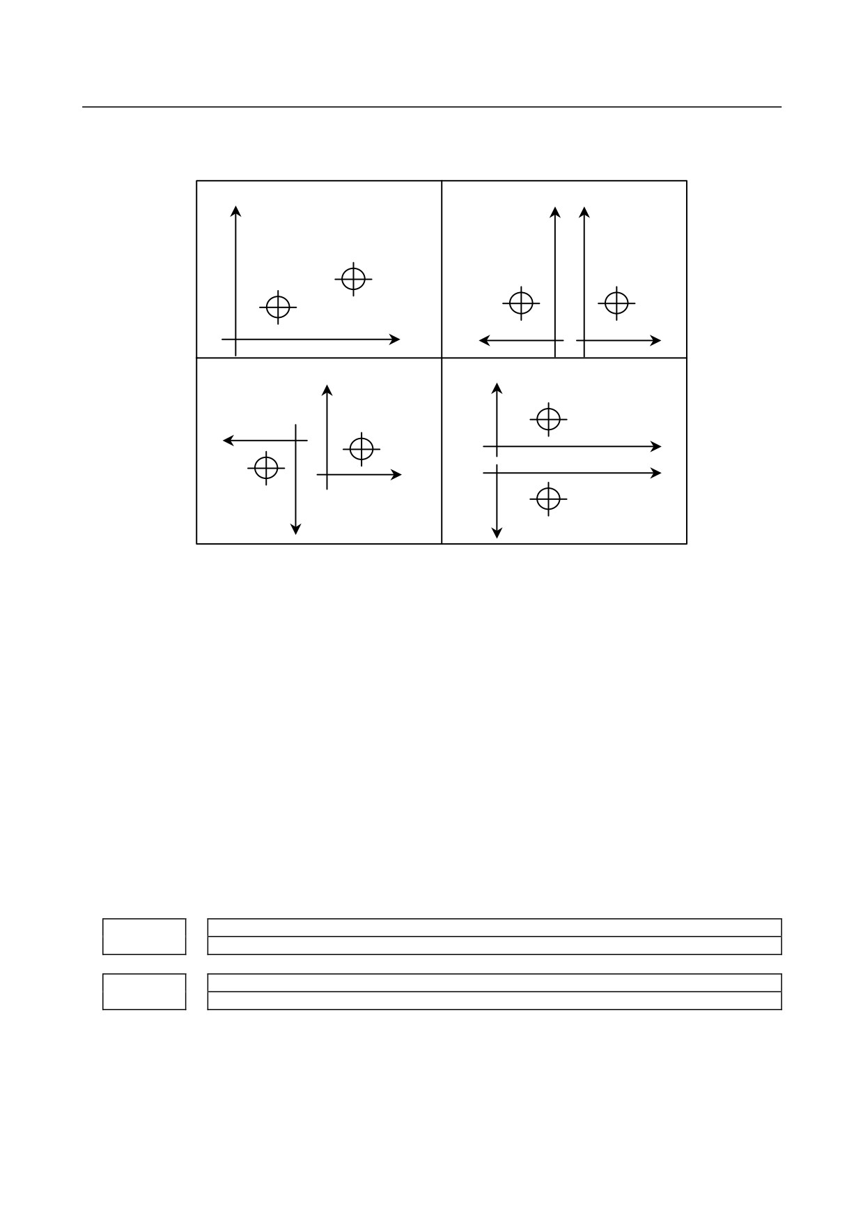
#0 TY0 This parameter sets the coordinate system relationship between two tool posts based on
the tool post of path 1.
#1 TY1
(1) When TY1=0 and TY0=0
(2) When TY1=0 and TY0=1
+X
+X
+X
Tool post 2
Tool post 1
Tool post 2
Tool post 1
+Z
+Z
+Z
(3) When TY1=1 and TY0=0
(4) When TY1=1 and TY0=1
+X
+X
+Z
Tool post 2
Tool post 1
+Z
+Z
Tool post 2
+Z
Tool post 1
+X
+X
#2 IT0 When offset number 0 is specified by the T code,
0: Checking interference between paths is stopped until an offset number other than 0
is specified by the next T code.
1: Checking interference between paths is continued according to the previously
specified offset number.
#3 IFM In manual mode, a interference check between paths is:
0: Not performed.
1: Performed.
#4 IFE Interference check between paths is:
0: Performed.
1: Not performed.
#5 ZCL Specifies whether interference along the Z axis is checked while checking interference
between paths.
0: Checked.
1: Not checked (Only interference along the X axis is checked.)
Distance along the X axis between the reference positions of tool posts 1 and 2
8151
Distance along the Z axis between the reference positions of tool posts 1 and 2
8152
[Input type] Parameter input
[Data type] Real
[Unit of data] mm, inch (machine unit)
[Min. unit of data] Depend on the increment system of the applied axis
[Valid data range] 9 digit of minimum unit of data (refer to standard parameter setting table (A))
(When the increment system is IS-B, -999999.999 to +999999.999)
- 331 -
4.DESCRIPTION OF PARAMETERS
B-64310EN/02
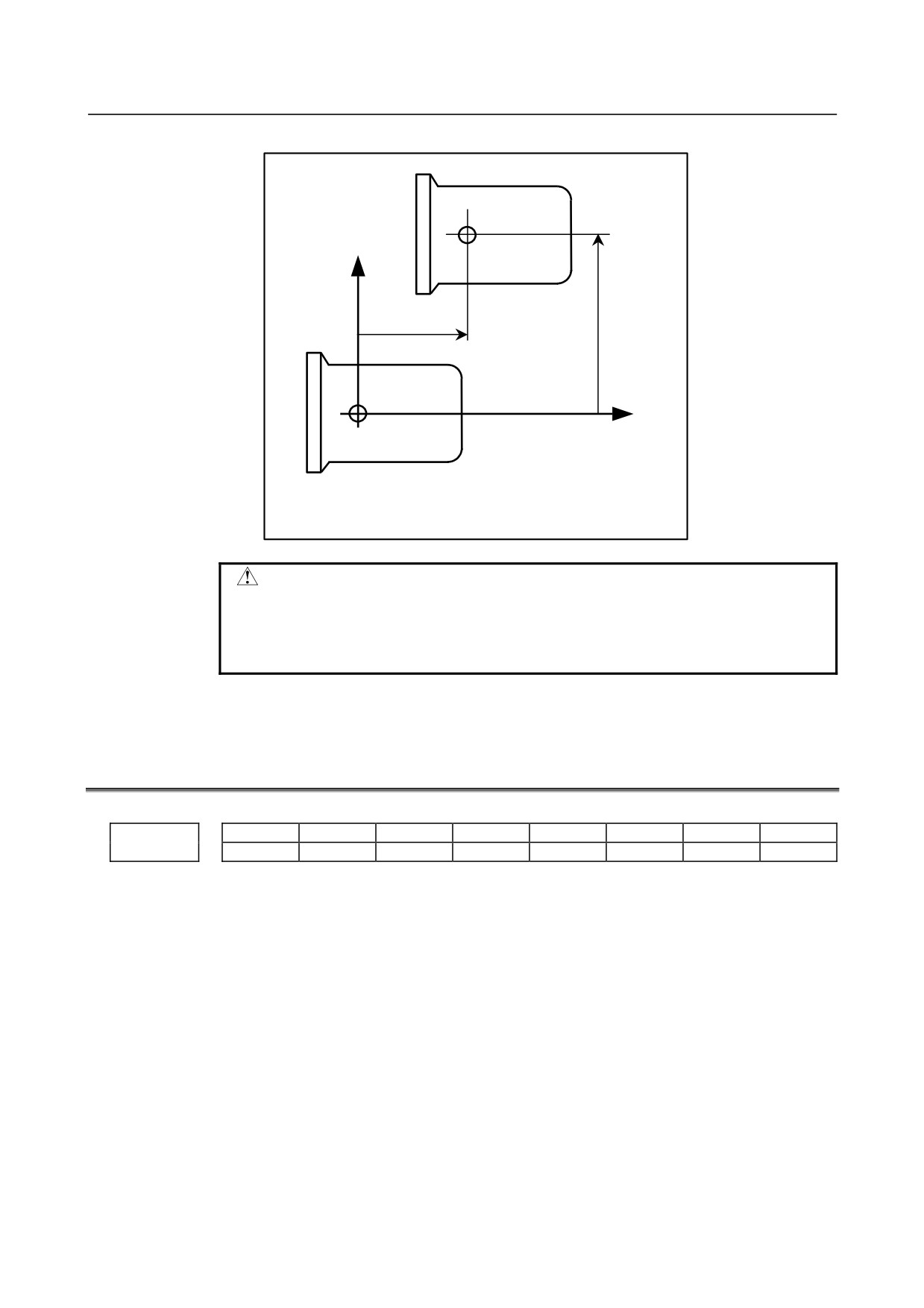
Each of these parameters sets the distance between the tool posts of two paths.
Tool post 2
Reference
position
+X
ζ
ε
+Z
Reference
position
Tool post 1
In the Z-X plane coordinate system with its origin at the represent position of tool
post 1, set the X component value ε of the reference position of tool post 2 in
parameter No. 8151 and set the Z component value ξ in parameter No. 8152.
WARNING
After modifying the parameter values, perform a manual reference
position return operation for both tool posts. Otherwise, the
internally stored positional relationships of the two tool posts are
not updated to the newly set parameter values.
4.53 PARAMETERS OF SYNCHRONOUS/COMPOSITE
CONTROL AND SUPERIMPOSED CONTROL (T SERIES)
(1 OF 2)
#7
#6
#5
#4
#3
#2
#1
#0
NRS
SPE
NCS
AXS
8160
[Input type] Parameter input
[Data type] Bit path
#4 AXS When the axis movement in-progress signal <Fn102> or the axis movement direction
signal <Fn106> of the slave axis in superimposed control is output:
0: State output is performed according to the result of adding superimposed move
pulses.
1: State output is performed according to the result of movement along each axis
instead of superimposed move pulses.
#5 NCS If an overtravel alarm is issued for an axis under synchronous, composite, or
superimposed control, synchronous, composite, or superimposed control is:
0: Released.
1: Not released.
- 332 -
B-64310EN/02
4.DESCRIPTION OF PARAMETERS
NOTE
If one of these paths is 1, both paths are assumed to be 1.
#6 SPE The synchronization deviation is:
0: The difference between the positioning deviation of the master axis and that of the
slave axis.
1: The difference between the positioning deviation of the master axis and that of the
slave axis plus the acceleration/deceleration delay.
NOTE
1 When the master and slave axes have different
acceleration/deceleration time constants, set 1.
2 SPE is valid when bit 1 (SERx) of parameter No. 8162 is set to 1.
SPE is used to find a synchronization deviation for comparison with
parameter No. 8181.
#7 NRS When the system is reset, synchronous, composite, or superimposed control is:
0: Released.
1: Not released.
#7
#6
#5
#4
#3
#2
#1
#0
NSR
CRZ
NMR
8161
[Input type] Parameter input
[Data type] Bit
#0 NMR When an axis subject to composite control is placed in servo-off state:
0: Composite control is stopped
1: Composite control is not stopped, provided bit 0 (FUP) of parameter No.1819 is set
to 1 to disable follow-up for the axis.
#5 CRZ If the state of the composite control signal is switched in composite control on two axes
under Cs contour control, the reference position establishment state of the two axes in
composite control is:
0: Maintained. (The unestablished state is not assumed.)
1: Assumed to be unestablished.
#7 NSR When servo-off occurs with an axis in synchronous control:
0: Synchronous control is canceled.
1: Synchronous control is not canceled if follow-up operation is disabled for the axis
(with bit 0 (FUPx) of parameter No. 1819 set to 1).
#7
#6
#5
#4
#3
#2
#1
#0
MUMx
MCDx
MPSx
MPMx
OMRx
PKUx
SERx
SMRx
8162
[Input type] Parameter input
[Data type] Bit axis
#0 SMRx Synchronous mirror-image control is:
0: Not applied. (The master and slave axes move in the same direction.)
1: Applied. (The master and slave axes move in opposite directions.)
- 333 -

4.DESCRIPTION OF PARAMETERS
B-64310EN/02
#1 SERx The synchronization deviation is:
0: Not detected.
1: Detected.
NOTE
When both master and slave axes move in synchronization, the
positioning deviations of the corresponding axes are compared with
each other. If the difference is greater than or equal to the value
specified in parameter No.8181, an alarm occurs. When either axis
is in the parking or machine-locked state, however, the
synchronization deviation is not detected.
#2
PKUx In the parking state,
0: The absolute, relative, and machine coordinates are not updated.
1: The absolute and relative coordinates are updated. The machine coordinates are not
updated.
NOTE
1 With an axis for which polar coordinate interpolation is specified,
set this parameter to 1. If this parameter is set to 0, a coordinate
shift can occur when a single block stop or feed hold is performed
in the polar coordinate interpolation mode.
2 With an axis that is set to function as a synchronous master axis
and synchronous slave axis at the same time (with bit 1 (SYWx) of
parameter No. 8167), set this parameter to 1.
#3 OMRx Superimposed mirror-image control is:
0: Not applied. (The superimposed pulse is simply added.)
1: Applied. (The inverted superimposed pulse is added.)
#4 MPMx When composite control is started, the workpiece coordinate system is:
0: Not set automatically.
1: Set automatically.
NOTE
When the workpiece coordinate system is automatically set at the
start of composite control, it is calculated from the following:
Current machine coordinates and the workpiece coordinates at the
reference point of each axis (parameter No.8184).
When the workpiece coordinate system is used (bit 0 (NWZ) of
parameter No. 8136 is 0), however, instead of the coordinates
obtained by the above calculation, the workpiece coordinates by
the operation of workpiece coordinate system presetting
(equivalent to G92.1 IP 0) in the machine coordinate system of the
composite partner axis are set.
#5 MPSx When composite control is terminated, the workpiece coordinate system is:
0: Not set automatically.
1: Set automatically.
- 334 -
B-64310EN/02
4.DESCRIPTION OF PARAMETERS
NOTE
When the workpiece coordinate system is automatically set at the
end of composite control, it is calculated from the following: Current
machine coordinates and the workpiece coordinates at the
reference point of each axis under composite control (parameter
No.1250)
When the workpiece coordinate system is used (bit 0 (NWZ) of
parameter No. 8136 is 0), however, instead of the coordinates
obtained by the above calculation, the workpiece coordinates by
the operation of workpiece coordinate system presetting
(equivalent to G92.1 IP 0) in the machine coordinate system of the
local axis are set.
#6
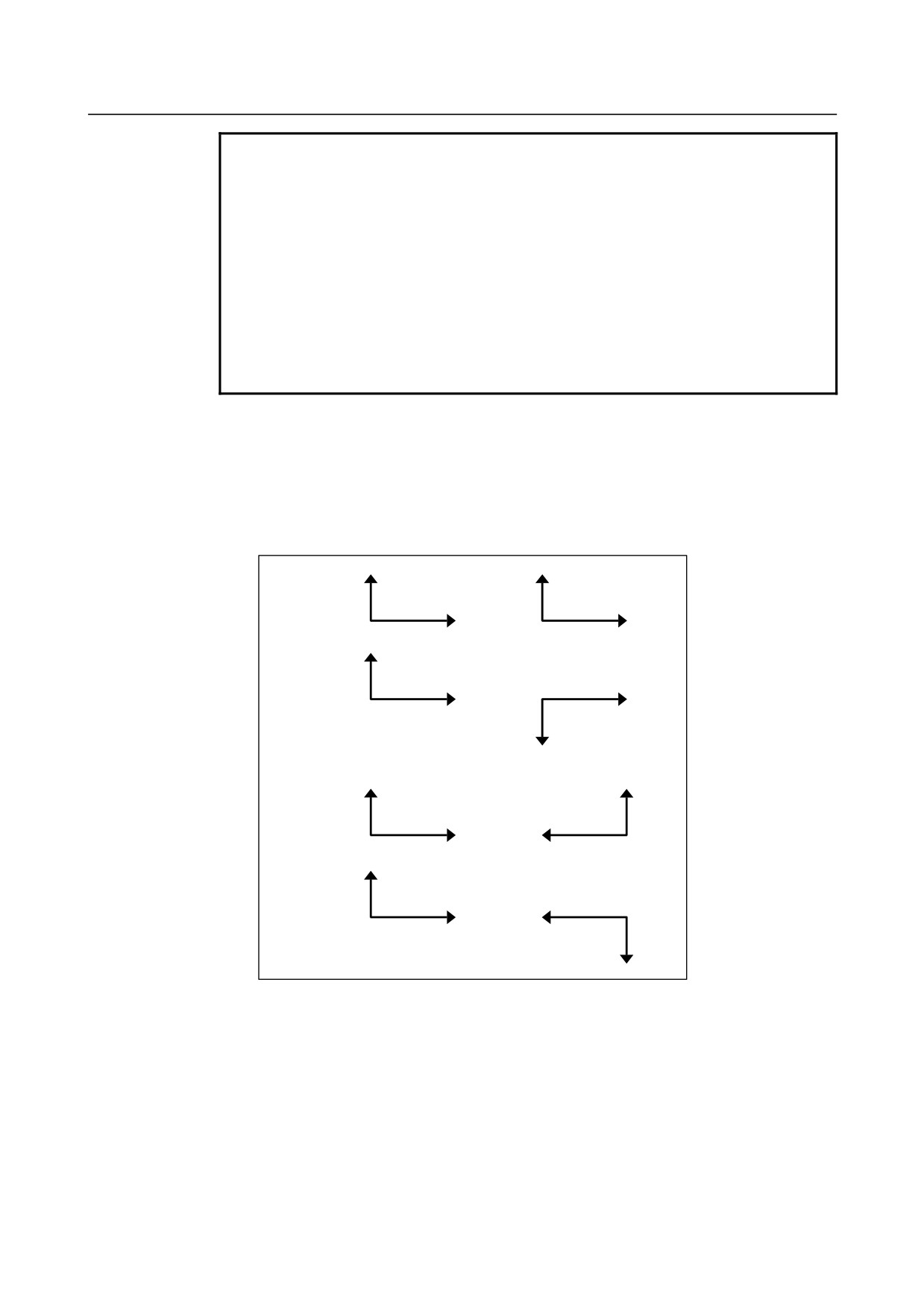
MCDx The axes to be replaced with each other under composite control have the coordinate
systems placed:
0:
In the same direction. Simple composite control is applied. (A movement is made in
the same direction along the corresponding axis.)
1:
In opposite directions. Mirror-image composite control is applied. (A movement is
made in the reverse direction along the corresponding axis.)
X1
X2
MCDz MCDx
0
0
Z1
Z2
X1
MCDz MCDx
0
1
Z1
Z2
X2
X1
X2
MCDz MCDx
1
0
Z1
Z2
X1
MCDz MCDx
1
1
Z1
Z2
X2
#7
MUMx In composite control, a move command for the axis:
0: Can be specified.
1: Cannot be specified.
- 335 -
4.DESCRIPTION OF PARAMETERS
B-64310EN/02
NOTE
Upon the execution of a move command along an axis for which
MUMx is set to 1 during mixed control, alarm PS0353 is issued. For
example, when axis X1 and axis X2 are placed under composite
control, and a command for axis X2 (motor for axis X1) is to be
disabled, set MUMx for path 2 to 1.
#7
#6
#5
#4
#3
#2
#1
#0
NUMx
MMIx
SMIx
SCDx
SCMx
SPSx
SPMx
8163
[Input type] Parameter input
[Data type] Bit axis
#1 SPMx When synchronous control is started, automatic workpiece coordinate system setting for
the master axis is
0: Not Performed.
1: Performed.
NOTE
When a workpiece coordinate system is automatically set at the
start of synchronous control, the workpiece coordinate system is
calculated from the current machine coordinates and the workpiece
coordinates of each axis at the reference position set in parameter
No.8185.
#2
SPSx When synchronous control terminates, automatic workpiece coordinate system setting for
the master axis is:
0: Not performed.
1: Performed.
NOTE
When a workpiece coordinate system is automatically set at the
end of synchronous control, the workpiece coordinate system is
calculated from the current machine coordinates and the workpiece
coordinates for each axis at the reference position set in parameter
No.1250.
#3
SCMx When workpiece coordinates are calculated in synchronous control:
0: The workpiece coordinates are calculated from the machine coordinates of the slave
axis.
1: The workpiece coordinates are calculated from the machine coordinates of the
master axis and slave axis.
#4 SCDx The positive (+) directions of the master axis and slave axis in the coordinate system in
synchronous control are:
0: Identical.
1: Opposite.
Set the parameters SPMx, SPSx, SCMx, and SCDx for the master axis. These settings are
referenced during automatic workpiece coordinate setting for the master axis at the start
of synchronous control.
- 336 -
B-64310EN/02
4.DESCRIPTION OF PARAMETERS
#5 SMIx In synchronous control, the manual handle interruption amount for the master axis or the
mirror image mode is:
0: Reflected in the slave axis.
1: Not reflected in the slave axis.
When this bit (SMIx) is set to 0
Manual handle interruption :
To the travel distance along the slave axis, the interruption amount of the master axis
is also added.
Mirror image :
When mirror image is applied to the master axis, mirror image is also applied to the
slave axis.
When this bit (SMIx) is set to 1
Manual handle interruption :
To the travel distance along the slave axis, the interruption amount of the master axis
is not added.
Mirror image :
Even when mirror image is applied to the master axis, mirror image is not applied to
the slave axis.
#6 MMIx For a composite control axis, manual handle interruption under composite control is:
0: Enabled.
1: Disabled.
#7 NUMx When neither synchronous control nor composite control is applied, a move command for
the axis is:
0: Not disabled.
1: Disabled.
NOTE
If a move command is specified for an axis with NUMx set to 1
when neither synchronous control nor composite control is applied,
alarm PS0353 is issued.
#7
#6
#5
#4
#3
#2
#1
#0
SOKx
OPSx
MCEx
MCSx
MWEx
MWSx
8164
[Input type] Parameter input
[Data type] Bit axis
#0 MWSx In automatic workpiece coordinate system setting, performed when composite control is
started, a workpiece shift and tool offset are:
0: Not considered.
1: Considered.
NOTE
MWSx is valid when bit 4 (MPMx) of parameter No. 8162 is 1 and
the workpiece coordinate system is not used (bit 0 (NWZ) of
parameter No. 8136 is 1).
- 337 -

4.DESCRIPTION OF PARAMETERS
B-64310EN/02
#1 MWEx In automatic workpiece coordinate system setting, performed when composite control is
canceled, a workpiece shift and tool offset are:
0: Not considered.
1: Considered.
NOTE
MWEx is valid when bit 5 (MPSx) of parameter No. 8162 is 1 and
the workpiece coordinate system is not used (bit 0 (NWZ) of
parameter No. 8136 is 1).
#2 MCSx In automatic workpiece coordinate system setting, performed when composite control is
started:
0: A workpiece coordinate system is automatically set in the same way as normal.
1: The coordinate system of the other path subject to axis recomposition is used.
NOTE
MCSx is valid when bit 4 (MPMx) of parameter No. 8162 is 1 and
the workpiece coordinate system is not used (bit 0 (NWZ) of
parameter No. 8136 is 1).
#3 MCEx In automatic workpiece coordinate system setting, performed when composite control is
canceled:
0: A workpiece coordinate system is automatically set in the same way as normal.
1: The coordinate system of the other path subject to axis recomposition is used.
NOTE
MCEx is valid when bit 5 (MPSx) of parameter No. 8162 is 1 and
the workpiece coordinate system is not used (bit 0 (NWZ) of
parameter No. 8136 is 1).
#5 OPSx When superimposed control is canceled, control in which an amount of movement along
a master axis subject to superimposed control is added to the workpiece coordinate of a
slave axis is:
0: Not applied.
1: Applied.
NOTE
When the workpiece coordinate system is enabled (bit 0 (NWZ) of
parameter No. 8136 is 0), the coordinate system is set by
workpiece coordinate system presetting (equivalent to G92.1 IP0).
#6 SOKx If a master axis subject to superimposed control is also subject to synchronous control:
0: An alarm is issued when superimposed control is started during synchronous
control.
1: No alarm is issued when superimposed control is started during synchronous
control.
#7
#6
#5
#4
#3
#2
#1
#0
MIX
8166
[Input type] Parameter input
- 338 -
B-64310EN/02
4.DESCRIPTION OF PARAMETERS
[Data type] Bit
NOTE
When this parameter is set, the power must be turned off before
operation is continued.
#1 MIX Composite control uses:
0: A new 2-path interface. In this case, the composite partner axis is set in parameter
No. 8183 and the signal of the axis set in parameter No. 8183 is used as the
composite control axis selection signal.
1: The conventional 2-path interface. In this case, parameter No. 8183 is set on path 2
and the signal on path 1 is used as the composite control axis selection signal.
#7
#6
#5
#4
#3
#2
#1
#0
SPVx
SWSx
SWMx
SGSx
SGMx
SYWx
8167
[Input type] Parameter input
[Data type] Bit axis
#1 SYWx The axis is:
0: Not used as a master axis and slave axis at the same time.
1: Used as a master axis and slave axis at the same time.
#2 SGMx In automatic workpiece coordinate system setting at the start of synchronous control, a
tool offset is:
0: Considered.
1: Not considered.
NOTE
SGMx is enabled when bit 1 (SPMx) of parameter No.8163 is set to
1.
#3 SGSx In automatic workpiece coordinate system setting at the end of synchronous control, a
tool offset is:
0: Considered.
1: Not considered.
NOTE
SGSx is enabled when bit 2 (SPSx) of parameter No.8163 or bit 6
(SPVx) of parameter No.8167 is set to 1.
#4 SWMx In automatic workpiece coordinate system setting at the start of synchronous control, a
workpiece shift is:
0: Not considered.
1: Considered.
NOTE
SWMx is enabled when bit 1 (SPMx) of parameter No.8163 is set
to 1.
- 339 -
4.DESCRIPTION OF PARAMETERS
B-64310EN/02
#5 SWSx In automatic workpiece coordinate system setting at the end of synchronous control, a
workpiece shift is:
0: Not considered.
1: Considered.
NOTE
SWSx is enabled when bit 2 (SPSx) of parameter No.8163 or bit 6
(SPVx) of parameter No.8167 is set to 1.
#6 SPVx At the end of synchronous control, automatic workpiece coordinate system setting for the
slave axis is:
0: Not performed.
1: Performed.
NOTE
When a workpiece coordinate system is automatically set at the
end of synchronous control, the workpiece coordinate system is
calculated from the current machine coordinates and the workpiece
coordinates for each axis at the reference position set in parameter
No.1250.
#7
#6
#5
#4
#3
#2
#1
#0
WST
MWR
SVF
MSO
MPA
8168
[Input type] Parameter input
[Data type] Bit
#0 MPA When an alarm about synchronization/composite/superposition control is issued:
0: Both paths are set to the feed hold state.
1: Only
the
path
that
includes
an
axis
related
to
synchronization/composite/superposition control is set to the feed hold state.
For example, in synchronization control within the same path, the path in which an
alarm occurred is set to the feed hold state.
#1 MSO When one of the following events occurs in synchronous control or composite control:
• The emergency stop signal is turned off.
• The servo-off signal is turned on.
• A servo alarm is issued.
0: The synchronous or composite control mode is canceled and follow-up operation is
not performed.
For the operation to be performed when the servo-off signal is turned on, however,
the setting of bit 7 (NSR) of parameter No. 8161 is used in synchronous control or
the setting of bit 0 (NMR) of parameter No. 8161 is used in composite control.
- 340 -

B-64310EN/02
4.DESCRIPTION OF PARAMETERS
1: The synchronous or composite control mode is not canceled. The following
operation is performed to perform follow-up operation:
When the emergency stop signal is turned off, if the other path is involved, the path
operates so that the emergency stop signal is virtually turned off.
When the servo-off signal is turned on, the relevant axis is determined and operation
is performed so that the servo-off signal is virtually turned on for the determined
axis.
When a servo alarm is issued, the relevant axis is determined and the alarm SV0003,
“CONTINUATION OF SYNCHRONOUS OR COMPOSITE CONTROL
DISABLED” is issued for the determined axis to stop moving the tool along the axis.
When bit 2 (SVF) of parameter No. 8168 is set to 1, this servo-off specification
follows the SVF setting.
NOTE
This setting is valid also during operation. For all axes placed under
synchronous or composite control, the emergency stop signal is
turned off, the servo-off signal is turned on, or a servo alarm is
issued.
#2
SVF When an axis under composite control is placed in the servo-off state:
0: Composite control is canceled.
1: Composite control is not canceled.
Follow-up specification follows the setting of bit 0 (FUPx) of parameter No. 1819.
When bit 2 (SVF) of parameter No. 8168 is set to 1, bit 0 (NMR) of parameter No. 8161
is invalid. Bit 1 (MSO) of parameter No. 8168, specification for servo-off, is also invalid.
NOTE
If a composite control axis is placed in the servo-off state when
stopped, set this parameter to 1.
#4 MWR When the workpiece coordinate system is automatically set if
synchronization/composite/superposition control is started or ended, the tool
compensation number is:
0: Canceled.
1: Not canceled.
NOTE
This parameter is valid when the workpiece coordinate system is
enabled (bit 0 (NWZ) of parameter No. 8136 is 0).
#6 WST When a workpiece coordinate system is automatically set up for a slave axis at the end of
synchronous control, workpiece coordinate system presetting is:
0: Not performed.
1: Performed.
NOTE
This parameter is valid when the workpiece coordinate system is
enabled (bit 0 (NWZ) of parameter No. 8136 is 0) and bit 6 (SPV)
of parameter No. 8167 is 1.
- 341 -
4.DESCRIPTION OF PARAMETERS
B-64310EN/02
#7
#6
#5
#4
#3
#2
#1
#0
MRFx
MVMx
MDMx
8169
[Input type] Parameter input
[Data type] Bit axis
#0 MDMx As machine coordinates in composite control:
0: Coordinates for the local path are displayed.
1: Coordinates for the other path in composite control are displayed.
#1 MVMx In composite control, machine coordinates (#5021 and above) to be read are:
0: Machine coordinates of the local path.
1: Machine coordinates of the other path in composite control.
#2 MRFx In composite control, the rapid traverse rate is:
0: The rapid traverse rate for the specified axis.
1: The rapid traverse rate for the axis along which a movement is made.
Master axis with which an axis is synchronized under synchronous control
8180
[Input type] Parameter input
[Data type] Word axis
[Valid data range] 101, 102, 103, . . . , (path number)*100+(intra-path relative axis number) (101, 102,
103, . . . , 201, 202, 203, . . .)
This parameter sets the path number and intra-path relative axis number of the master axis
with which each axis is synchronized. When zero is specified, the axis does not become a
slave axis and is not synchronized with another axis. When an identical number is
specified in two or more parameters, one master axis has two or more slave axes.
Synchronization error limit of each axis
8181
[Input type] Parameter input
[Data type] 2-word axis
[Unit of data] Detection unit
[Valid data range] 0 to 99999999
When the synchronization deviation detected (bit 1 (SERx) of parameter No.8162 is set to
1), this parameter specifies the limit of the difference between the positioning deviation
of the slave axis and that of the master axis. Set this parameter to the slave axis.
Composite control axis of the other path in composite control for each axis
8183
[Input type] Parameter input
[Data type] Word axis
[Valid data range] 101, 102, 103, . . . , (path number)*100+(intra-path relative axis number) (101, 102,
103, . . . , 201, 202, 203, . . . )
This parameter sets with which axis each axis is to be placed under composite control.
When zero is specified, control of the axis is not replaced under composite control. An
identical number can be specified in two or more parameters, but composite control
cannot be exercised for all of them at a time.
- 342 -
B-64310EN/02
4.DESCRIPTION OF PARAMETERS
NOTE
When using the conventional 2-path interface (bit 1 (MIX) of
parameter No. 8166 is 1, set this parameter on path 2. In this
case, use the composite control axis selection signal on path 1.
Coordinates of the reference point of an axis on the coordinate system of another axis under
8184
composite control
[Input type] Parameter input
[Data type] Real axis
[Unit of data] mm, inch, degree (input unit)
[Min. unit of data] Depend on the increment system of the applied axis
[Valid data range] 9 digit of minimum unit of data (refer to standard parameter setting table (A))
(When the increment system is IS-B, -999999.999 to +999999.999)
This parameter specifies the coordinates of the reference point of an axis on the
coordinate system of another axis under composite control.
This parameter is valid when bit 4 (MPMx) of parameter No. 8162 is 1 and the workpiece
coordinate system is not used (bit 0 (NWZ) of parameter No. 8136 is 1).
[Example] Exercising composite control to replace the X1-axis with the X2-axis
X1m
ΔZ2m
Z1m
Zero point of the
X1
workpiece coordinate
Reference
ΔX2m
system of path 2
position of path 1
Zero point of the
Z1
Z2
workpiece coordinate
system of path 1
Reference
ΔX1m
X2
position of path 2
Z2m
ΔZ1m
X2m
(ΔX1m, ΔZ1m) are the coordinates of the reference point of path 2 on the workpiece
coordinate system of path 1. (ΔX2m, ΔZ2m) are the coordinates of the reference point of
path 1 on the workpiece coordinate system of path 2.
ΔX1m is specified for the parameter No. 8184x of path 1 and ΔX2m for the parameter No.
8184x of path 2.
If bit 4 (MPMx) of parameter No.8162 is set to 1 when composite control is started, the
workpiece coordinate system satisfying the following conditions is specified:
X1 = (Value specified for the X-axis of path 1) ± (Machine coordinate of X2)
Plus when parameter MCDx (bit 6 of No.8162) of path 1 is set to 0
Minus when parameter MCDx (bit 6 of No.8162) of path 1 is set to 1
X2 = (Value specified for the X-axis of path 2) ± (Machine coordinate of X1)
Plus when parameter MCDx (bit 6 of No.8162) of path 2 is set to 0
Minus when parameter MCDx (bit 6 of No.8162) of path 2 is set to 1
- 343 -
4.DESCRIPTION OF PARAMETERS
B-64310EN/02
If bit 5 of parameter No.8162 MPSx is set to 1 when composite control is terminated, the
workpiece coordinate system satisfying the following conditions is specified:
X1 = (Parameter No.1250 of path 1) + (Machine coordinate of X1)
X2 = (Parameter No.1250 of path 2) + (Machine coordinate of X2)
Workpiece coordinates on each axis at the reference position
8185
[Input type] Parameter input
[Data type] Real axis
[Unit of data] mm, inch, degree (input unit)
[Min. unit of data] Depend on the increment system of the applied axis
[Valid data range] 9 digit of minimum unit of data (refer to standard parameter setting table (A))
(When the increment system is IS-B, -999999.999 to +999999.999)
This parameter sets the workpiece coordinates on each master axis, subject to
synchronous control, when the master and slave axes are at the reference position. This
parameter is enabled when bit 1 (SPMx) of parameter No.8163 is set to 1. Set this
parameter for the master axis.
Master axis under superimposed control
8186
[Input type] Parameter input
[Data type] Word axis
[Valid data range] 101, 102, 103, . . . , (path number)*100+(intra-path relative axis number) (101, 102,
103, . . . , 201, 202, 203, . . . )
This parameter sets the path number and intra-path relative axis number of a
superimposed master axis for each axis when superimposed control is exercised. When
zero is specified, the axis does not become a slave axis under superimposed control and
the move pulse of another axis is not superimposed.
An identical number can be specified in two or more parameters to exercise superimposed
control simultaneously. This means that superimposed control with one master axis and
multiple slave axes is possible.
A slave axis may function as the master axis of another axis to allow three-generation
superimposed control: parent (master axis) - child (slave axis/master axis) - grandchild
(slave axis).
In this case, a movement along the child is made by its travel distance plus the travel
distance of the parent, and a movement along the grandchild is made by its travel distance
plus the travel distance of the child plus the travel distance of the parent.
Example of the relationship of parent (X1 of path 1) - child (X2 of path 2) - grandchild
(U2 of path 2):
The travel distance of X1 is superimposed on X2, and the travel distances of X1 and X2
are further superimposed on U2.
Parameter No. 8186x of path 2 = 101
Parameter No. 8186u of path 2 = 201
4.54
PARAMETERS OF ANGULAR AXIS CONTROL
#7
#6
#5
#4
#3
#2
#1
#0
8200
AZR
AAC
[Input type] Parameter input
- 344 -
B-64310EN/02
4.DESCRIPTION OF PARAMETERS
[Data type] Bit path
NOTE
When at least one of these parameters is set, the power must be
turned off before operation is continued.
#0 AAC
0: Does not perform angular axis control.
1: Performs inclined axis control.
#2 AZR
0: The machine tool is moved along the Cartesian axis during manual reference
position return along the slanted axis under angular axis control.
1: The machine tool is not moved along the Cartesian axis during manual reference
position return along the slanted axis under angular axis control.
#7
#6
#5
#4
#3
#2
#1
#0
8201
ADG
AO3
AO2
AOT
[Input type] Parameter input
[Data type] Bit path
NOTE
When at least one of these parameters is set, the power must be
turned off before operation is continued.
#0 AOT Stored stroke limit 1 under angular axis control is handled as:
0: Value in the slanted coordinate system.
1: Value in the Cartesian coordinate system.
#1 AO2 Stored stroke limit 2 under angular axis control is handled as:
0: Value in the slanted coordinate system.
1: Value in the Cartesian coordinate system.
#2 AO3 Stored stroke limit 3 under angular axis control is handled as:
0: Value in the slanted coordinate system.
1: Value in the Cartesian coordinate system.
#7 ADG The contents of diagnostic data Nos. 306 and 307 are:
0: Not swapped. The slanted axis and Cartesian axis are displayed in this order.
1: Swapped. The Cartesian axis and slanted axis are displayed in this order.
#7
#6
#5
#4
#3
#2
#1
#0
8209
ARF
[Input type] Parameter input
[Data type] Bit path
NOTE
When this parameter bit is set, the power must be turned off before
operation is continued.
- 345 -
4.DESCRIPTION OF PARAMETERS
B-64310EN/02
#0 ARF In angular axis control, a movement from an intermediate point to the reference position
in the G28/G30 command is:
0: Made in the angular coordinate system.
1: Made in the Cartesian coordinate system.
8210
Slant angle of a slanted axis in angular axis control
[Input type] Parameter input
[Data type] Real path
[Unit of data] Degree
[Min. unit of data] Depend on the increment system of the applied axis
[Valid data range] -180.000 to 180.000. However, angular axis control is disabled in the ranges -95.000 to
-85.000 and 85.000 to 95.000 (in the case of IS-B).
8211
Axis number of a slanted axis subject to angular axis control
8212
Axis number of a Cartesian axis subject to slanted axis control
NOTE
When these parameters are set, the power must be turned off before
operation is continued.
[Input type] Parameter input
[Data type] Word path
[Valid data range] 1 to number of controlled axes
When angular axis control is to be applied to an arbitrary axis, these parameters set the
axis numbers of a slanted axis and Cartesian axis. If 0 is set in either of the two
parameters, the same number is set in the two parameters, or a number other than the
controlled axis numbers is set in either of the two parameters, a slanted axis and Cartesian
axis are selected as indicated in the following table:
Slanted axis
Cartesian axis
Y-axis (axis with 2 set in parameter No.
Z-axis (axis with 3 set in parameter No.
M series
1022) of the basic three axes
1022) of the basic three axes
X-axis (axis with 1 set in parameter No.
Z-axis (axis with 3 set in parameter No.
T series
1022) of the basic three axes
1022) of the basic three axes
4.55 PARAMETERS OF AXIS SYNCHRONOUS CONTROL
#7
#6
#5
#4
#3
#2
#1
#0
8301
SYA
[Input type] Parameter input
[Data type] Bit path
#4 SYA In the servo-off state in axis synchronous control, the limit of the difference between the
positioning deviation of the master axis and that of the slave axis is:
0: Checked.
1: Not checked.
#7
#6
#5
#4
#3
#2
#1
#0
8302
SMA
[Input type] Parameter input
- 346 -
B-64310EN/02
4.DESCRIPTION OF PARAMETERS
[Data type] Bit path
NOTE
When this parameter is set, the power must be turned off before
operation is continued.
#7 SMA When an absolute position detector is attached, and bit 4 (APZ) of parameter No. 1815
for an axis in synchronous operation is set to OFF, APZ of the pairing axis
in
synchronous operation is:
0: Not set to OFF.
1: Set to OFF.
#7
#6
#5
#4
#3
#2
#1
#0
8303
SOFx
SYPx
SAFx
ATSx
ATEx
[Input type] Parameter input
[Data type] Bit axis
NOTE
When at least one of these parameters is set, the power must be
turned off before operation is continued.
#0 ATEx In axis synchronous control, automatic setting for grid positioning is:
0: Disabled
1: Enabled
Set this parameter with a slave axis.
#1 ATSx In axis synchronous control, automatic setting for grid positioning is:
0: Not started
1: Started
Set this parameter with a slave axis.
NOTE
When starting automatic setting for grid positioning, set ATS to 1.
Upon the completion of setting, ATS is automatically set to 0.
#2 SAFx In axis synchronous control, a movement along a slave axis is:
0: Not added to actual feedrate display.
1: Added to actual feedrate display.
Set this parameter with a slave axis.
#4 SYPx In axis synchronous control, some parameters must be set to the same value for the master
and slave axes. When a value is set in such a parameter for the master axis:
0: The same value is not automatically set in the parameter for the slave axis.
1: The same value is automatically set in the parameter for the slave axis.
NOTE
1 For the parameters that can be set automatically, refer to
Subsection 1.6.7, "Automatic Setting of Parameters for Slave
Axes", in Connection Manual (Function) (B-64903EN-1).
2 Set this parameter for both the master and slave axes.
- 347 -
4.DESCRIPTION OF PARAMETERS
B-64310EN/02
#7 SOFx In axis synchronous control, the synchronization establishment function based on
machine coordinates is:
0: Disabled.
1: Enabled.
Set this parameter with a slave axis.
0.
#7
#6
#5
#4
#3
#2
#1
#0
8304
SYEx
SCAx
MVBx
ADJx
SSAx
[Input type] Parameter input
[Data type] Bit axis
#0 SSAx When the one-direction synchronization establishment function under axis synchronous
control is used:
0: The axis with a larger machine coordinate is used as the reference.
1: The axis with a smaller machine coordinate is used as the reference.
NOTE
1 When at least one of these parameters is set, the power must be
turned off before operation is continued.
2 Set this parameter (SSA) to the same value for both the master
and slave axes.
#2 ADJx In axis synchronous control, this parameter specifies an axis along which a movement is
made in the modification mode.
0: A movement is not made in the modification mode along the axis.
1: A movement is made in the modification mode along the axis.
When this parameter is set to 1, the modification mode is set.
Along an axis with this parameter set to 1, a movement is made by a move command for
the master axis.
Set this parameter for one of the master and slave axes.
When there are multiple slave axes for one master axis, set this parameter to 1 for an axis
with which a synchronization error excessive alarm is issued for recovery. If an alarm is
issued with multiple axes, modify this parameter after recovery of one axis to recover
another axis.
#4 MVBx In the modification mode, a move command in a direction that increases a
synchronization error is:
0: Ignored.
1: Valid.
When there are multiple slave axes for one master axis, an attempt to reduce the
synchronous error of a slave axis by a movement along the master axis can increase the
synchronization error of another slave axis. If this parameter is set to 0 in such a case, a
movement can be made in neither direction along the master axis. In this case, set bit 2
(ADJ) of parameter No. 8304 to make a movement along a slave axis to perform a
corrective operation.
#5 SCAx In axis synchronous control:
0: Synchronous operation is performed when the axis synchronous control manual feed
selection signal SYNCJ or the axis synchronous control selection signal SYNC for
slave axes is set to 1.
1: Synchronous operation is performed at all times.
Set this parameter with a slave axis.
- 348 -
B-64310EN/02
4.DESCRIPTION OF PARAMETERS
#7 SYEx When external machine coordinate system shift is specified by external data input/output
for the master axis in synchronous control, the slave axis is:
0: Not shifted.
1: Shifted by the same amount as specified for the master axis.
Set this parameter for the slave axis.
This function is disabled during normal operation.
#7
#6
#5
#4
#3
#2
#1
#0
8305
SRF
SSE
SSO
[Input type] Parameter input
[Data type] Bit path
#0 SSO The uni-directional synchronization function in axis synchronous control is:
0: Disabled.
1: Enabled.
#1 SSE After emergency stop, the uni-directional synchronization function in axis synchronous
control is:
0: Disabled.
1: Enabled.
#2 SRF In axis synchronous control, G27, G28, G30, and G53:
0: Make the same movement along the slave axis as a movement along the master axis.
1: Make movements along the slave axis and master axis independently to specified
positions.
8311
Axis number of master axis in axis synchronous control
NOTE
When this parameter is set, the power must be turned off before
operation is continued.
[Input type] Parameter input
[Data type] Byte axis
[Valid data range] 0 to Number of controlled axes
Select a master axis in axis synchronous control. In the parameter for the slave axis, set
the axis number of the master axis.
[Example 1] When one set of axis synchronous control is used:
When the master axis is the first axis (X-axis), and the slave axis is the third axis (Z-axis),
set parameter No. 8311 as follows:
Parameter No.8311 X (first axis) = 0
Parameter No.8311 Y (second axis) = 0
Parameter No.8311 Z (third axis) = 1
Parameter No.8311 A (fourth axis) = 0
[Example 2] When two sets of axis synchronous control is used:
When the master axes are the first axis and second axis, and the slave axes are the fourth
axis and third axis, set parameter No. 8311 as follows:
Parameter No.8311 X (first axis) = 0
Parameter No.8311 Y (second axis) = 0
Parameter No.8311 Z (third axis) = 2
Parameter No.8311 A (fourth axis) = 1
- 349 -
4.DESCRIPTION OF PARAMETERS
B-64310EN/02
8312
Enabling/disabling mirror image in axis synchronous control
[Input type] Parameter input
[Data type] Word axis
[Valid data range] -127 to 128
This parameter sets mirror image for the slave axis. When 100 or a more value is set with
this parameter, the mirror image function is applied to synchronous control. Set this
parameter to the slave axis.
[Example] For reverse synchronization with the master axis being the third axis and the slave axis
being the fourth axis, set parameter No. 8312 as follows:
Parameter No.8312 X (first axis) = 0
Parameter No.8312 Y (second axis) = 0
Parameter No.8312 Z (third axis) = 0
Parameter No.8312 A (fourth axis) = 100
NOTE
In synchronous operation with mirror image applied,
synchronization establishment, synchronization error checking, and
modification mode cannot be used.
8314
Maximum allowable error in synchronization error check based on machine coordinates
[Input type] Parameter input
[Data type] Real axis
[Unit of data] mm, inch, degree (machine unit)
[Min. unit of data] Depend on the increment system of the applied axis
[Valid data range] 0 or positive 9 digit of minimum unit of data (refer to the standard parameter setting table
(B))
(When the increment system is IS-B, 0.0 to +999999.999)
This parameter sets a maximum allowable error in a synchronization error check based on
machine coordinates. When the error between the master and slave axes in machine
coordinates exceeds the value set in this parameter, the machine stops with the servo
alarm (SV0005).
Set this parameter with a slave axis.
NOTE
Set 0 in this parameter when a synchronization error check is not
made.
8323
Limit in positional deviation check in axis synchronous control
[Input type] Parameter input
[Data type] 2-word axis
[Unit of data] Detection unit
[Valid data range] 0 to 999999999
This parameter sets the maximum allowable difference between the master axis and slave
axis position deviations. When the absolute value of a positional deviation difference
exceeds the value set in this parameter in axis synchronous control, the alarm (DS0001) is
issued.
Set this parameter with a slave axis. If 0 is specified in this parameter, no position
deviation difference check is made.
- 350 -

B-64310EN/02
4.DESCRIPTION OF PARAMETERS
8325
Maximum compensation value in synchronization establishment based on machine coordinates
[Input type] Parameter input
[Data type] Real axis
[Unit of data] mm, inch, degree (machine unit)
[Min. unit of data] Depend on the increment system of the applied axis
[Valid data range] 0 or positive 9 digit of minimum unit of data (refer to the standard parameter setting table
(B))
(When the increment system is IS-B, 0.0 to +999999.999)
This parameter sets the maximum compensation value for synchronization. When a
compensation value exceeding the value set in this parameter is detected, the servo alarm
(SV0001) is issued, and the synchronization establishment is not performed.
Specify a slave axis for this parameter. To enable this parameter, set the parameter SOF
(bit
7 of parameter No.8303) to 1. When 0 is set in this parameter, synchronization
establishment is not performed.
8326
Difference between master axis and slave axis reference counters
[Input type] Parameter input
[Data type] 2-word axis
[Unit of data] Detection unit
[Valid data range] 0 to 999999999
The difference between the master axis reference counter and slave axis reference counter
(master axis and slave axis grid shift) is automatically set when automatic setting for grid
positioning is performed. Then, the difference is transferred together with an ordinary
grid shift value to the servo system when the power is turned on. This parameter is set
with a slave axis.
8327
Torque difference alarm detection timer
[Input type] Parameter input
[Data type] 2-word axis
[Unit of data] msec
[Valid data range] 0 to 4000
This parameter sets a time from the servo preparation completion signal, SA <F000.6>,
being set to 1 until torque difference alarm detection is started in axis synchronous
control.
When 0 is set in this parameter, the specification of 512 msec is assumed.
Set this parameter with a slave axis.
8337
M code for turning off synchronization in axis synchronous control
[Input type] Parameter input
[Data type] 2-word path
[Valid data range] 1 to 99999999
This parameter specifies an M code for switching from synchronous operation to normal
operation.
The M code set in this parameter is not buffered.
8338
M code for turning on synchronization in axis synchronous control
[Input type] Parameter input
[Data type] 2-word path
[Valid data range] 1 to 99999999
- 351 -
4.DESCRIPTION OF PARAMETERS
B-64310EN/02
This parameter specifies an M code for switching from normal operation to synchronous
operation.
The M code set in this parameter is not buffered.
4.56 PARAMETERS OF SEQUENCE NUMBER COMPARISON
AND STOP
8341
Program number subject to comparison and stop
[Input type] Setting input
[Data type] 2-word path
[Valid data range] 1 to 9999
This parameter sets the program number, including a sequence number, subject to
sequence number comparison and stop. Parameter No.8342 is used to set a sequence
number subject to check termination.
8342
Sequence number subject to comparison and stop
[Input type] Setting input
[Data type] 2-word path
[Valid data range] 0 to 99999
This parameter sets the sequence number subject to sequence number comparison and
stop.
If the block containing the sequence number set with this parameter is executed while the
program set with parameter No.8341 is being executed, a single block stop occurs after
the block is executed. At this time, the setting is automatically set to -1.
NOTE
1 When -1 is set in parameter No. 8342, comparison and stop is
disabled.
2 Comparison and stop cannot be performed using a sequence
number contained in a block (such as a macro statement, M98, and
M99) that is processed only inside the CNC.
3 When a match is found with the sequence number of a block (such
as an L specification of a canned cycle) that specifies the number
of repeats, operation stops after executing as many times as the
number of repeats.
4 If the sequence number set in parameter No. 8342 appears more
than once in the program, operation stops at the block where the
first match is found in the order of execution.
4.57
PARAMETERS OF ADVANCED PREVIEW CONTROL / AI
ADVANCED PREVIEW CONTROL / AI CONTOUR
CONTROL / AI CONTOUR CONTROL II (1 OF 2)
#7
#6
#5
#4
#3
#2
#1
#0
8451
NOF
ZAG
[Input type] Setting input
[Data type] Bit path
- 352 -