FANUC Series 0i-MODEL D, Series 0i Mate-MODEL D. PARAMETER MANUAL - page 10
B-64310EN/02
4.DESCRIPTION OF PARAMETERS
The accumulated pulses and positional deviation due to actual acceleration/deceleration
when the skip signal or measurement position arrival signal goes on are considered to
obtain the position at which the signal is input.
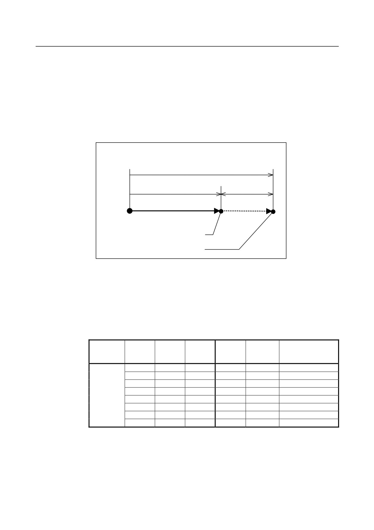
#2 TSE In a skip by the torque limit skip command (G31P98/P99):
0: A servo delay amount (positional deviation) is considered (system variables #5061
to
#5065 store positions corrected in consideration of the servo system delay
amount).
1: A servo delay amount (positional deviation) is not considered (system variables
#5061 to #5065 store positions corrected without consideration of the servo system
delay amount).
Position during skip operation
Current position of CNC
Machine position
Error amount
Origin of the coordinate system
Stop point
Position in consideration of delay
Position without consideration of delay
#4 IGX When the high-speed skip function is used, SKIP, SKIPP, and SKIP2 to SKIP8 are:
0: Enabled as skip signals.
1: Disabled as skip signals.
#7
SPE For the skip function (G31), the skip signal SKIP is:
0: Enabled.
1: Disabled.
Whether the skip signals are enabled or disabled
IGX
GSK
SPE
Skip
Skip
Multistage skip
Parameter
(No.6201
(No.6200
(No.6201
signal
signal
signals
#4)
#0)
#7)
SKIPP
SKIP
SKIP2-SKIP8
0
0
0
Disabled
Enabled
Enabled
0
1
0
Enabled
Enabled
Enabled
0
0
1
Disabled
Disabled
Enabled
0
1
1
Enabled
Disabled
Enabled
Setting
1
0
0
Disabled
Disabled
Disabled
1
1
0
Disabled
Disabled
Disabled
1
0
1
Disabled
Disabled
Disabled
1
1
1
Disabled
Disabled
Disabled
Bit 4 (IGX) of parameter No. 6201 is valid for the skip function using high-speed skip
signals (when bit 4 (HSS) of parameter No. 6200 is set to 1) or for the multistage skip
function using high-speed skip signals (when bit 5 (SLS) of parameter No. 6200 is set to
1).
To use multistage skip signals, the multistage skip function option is required.
- 263 -
4.DESCRIPTION OF PARAMETERS
B-64310EN/02
#7
#6
#5
#4
#3
#2
#1
#0
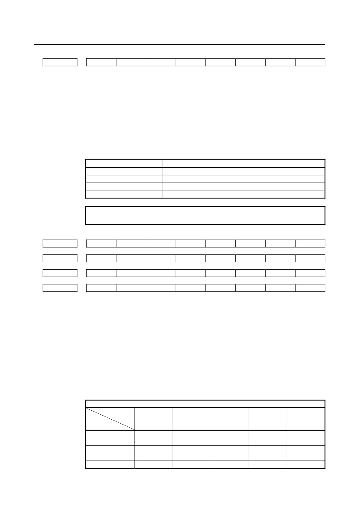
6202
1S8
1S7
1S6
1S5
1S4
1S3
1S2
1S1
[Input type] Parameter input
[Data type] Bit path
1S1 to 1S8 These parameters specify whether to enable or disable each high-speed skip signal when
the G31 skip command is issued.
The following table shows the correspondence between the bits, input signals, and
commands.
The settings of the bits have the following meaning :
0: The high-speed skip signal corresponding to a bit is disabled.
1: The high-speed skip signal corresponding to a bit is enabled.
Parameter
High-speed skip signals
1S1
HDI0
1S2
HDI1
1S3
HDI2
1S4
HDI3
NOTE
Do not specify the same signal simultaneously for different paths.
#7
#6
#5
#4
#3
#2
#1
#0
6203
2S8
2S7
2S6
2S5
2S4
2S3
2S2
2S1
#7
#6
#5
#4
#3
#2
#1
#0
6204
3S8
3S7
3S6
3S5
3S4
3S3
3S2
3S1
#7
#6
#5
#4
#3
#2
#1
#0
6205
4S8
4S7
4S6
4S5
4S4
4S3
4S2
4S1
#7
#6
#5
#4
#3
#2
#1
#0
6206
DS8
DS7
DS6
DS5
DS4
DS3
DS2
DS1
[Input type] Parameter input
[Data type] Bit path
1S1to1S8, 2S1to2S8, 3S1to3S8, 4S1to4S8, DS1toDS8
Specify which skip signal is enabled when the skip command (G31, or G31P1 to G31P4)
and the dwell command (G04, G04Q1 to G04Q4) are issued with the multi-step skip
function.
The following table shows the correspondence between the bits, input signals, and
commands.
The setting of the bits have the following meaning :
0: The skip signal corresponding to a bit is invalid.
1: The skip signal corresponding to a bit is enabled.
Multi-step skip function
Command
G31
Input
G31P1
G31P2
G31P3
G31P4
G04
signal
G04Q1
G04Q2
G04Q3
G04Q4
SKIP/HDI0
1S1
2S1
3S1
4S1
DS1
SKIP2/HDI1
1S2
2S2
3S2
4S2
DS2
SKIP3/HDI2
1S3
2S3
3S3
4S3
DS3
SKIP4/HDI3
1S4
2S4
3S4
4S4
DS4
SKIP5
1S5
2S5
3S5
4S5
DS5
- 264 -
B-64310EN/02
4.DESCRIPTION OF PARAMETERS
Multi-step skip function
Command
G31
Input
G31P1
G31P2
G31P3
G31P4
G04
signal
G04Q1
G04Q2
G04Q3
G04Q4
SKIP6
1S6
2S6
3S6
4S6
DS6
SKIP7
1S7
2S7
3S7
4S7
DS7
SKIP8
1S8
2S8
3S8
4S8
DS8
NOTE
HDI0 to HDI3 are high-speed skip signals. Do not specify the same
signal simultaneously for different paths.
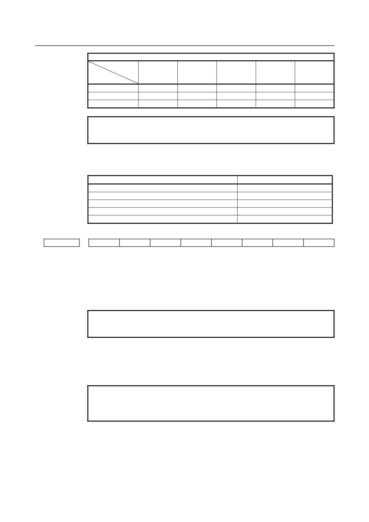
When bit 0 (GSK) of parameter No. 6200 is set to 1, commands to be skipped can be
selected by setting the following parameter:
Commands skipped by SKIPP signal <G006.6>
Parameter
Command skipped
When bit 0 (1S1) of parameter No. 6202 is set to 1
G31P1,G04Q1
When bit 0 (2S1) of parameter No. 6203 is set to 1
G31P2,G04Q2
When bit 0 (3S1) of parameter No. 6204 is set to 1
G31P3,G04Q3
When bit 0 (4S1) of parameter No. 6205 is set to 1
G31P4,G04Q4
When bit 6 (DS1) of parameter No. 6206 is set to 1
G04,G04Q1,G04Q2,G04Q3,G04Q4
#7
#6
#5
#4
#3
#2
#1
#0
6207
RHB
SFN
SFP
[Input type] Parameter input
[Data type] Bit path
#1 SFP The feedrate used when the skip function (G31) is being executed is:
0: Feedrate of a programmed F code.
1: Feedrate set in parameter No. 6281.
NOTE
For the multi-stage skip function and high-speed skip, see the
description of bit 2 (SFN ) of parameter No. 6207.
#2 SFN The feedrate used when the skip function based on high-speed skip signals (with bit 4
(HSS) of parameter No. 6200 set to 1) or the multi-skip function is being executed is:
0: Feedrate of a programmed F code.
1: Feedrate set in a parameter from parameter No. 6282 to No. 6285.
NOTE
For not the multistage skip function, but the skip function using no
high-speed skip signals (when bit 4 (HSS) of parameter No. 6200 is
set to 0), see the description of bit 1 (SFP) of parameter No. 6207.
#5 RHB The high-Speed skip status signals HDO is:
0: Set to "1" when the contact of the high-speed skip signal is closed.
1: Set to "1" when the contact of the high-speed skip signal is open.
- 265 -
4.DESCRIPTION OF PARAMETERS
B-64310EN/02
NOTE
The high-speed skip signal HDI does not change by setting RHB
(bit 5 of parameter No.6207). When the contact of the high-speed
skip signal is open, the signal HDI is set to "0" and the signal is not
assumed to be input regardless of the setting of parameter RHB.
To assume that the high-speed skip signal is input when the
contact of the signal is open, set SRE (bit 6 of parameter No.6200)
to 1.
#7
#6
#5
#4
#3
#2
#1
#0
6210
MDC
ASB
ASL
[Input type] Parameter input
[Data type] Bit path
#3 ASL
#4 ASB
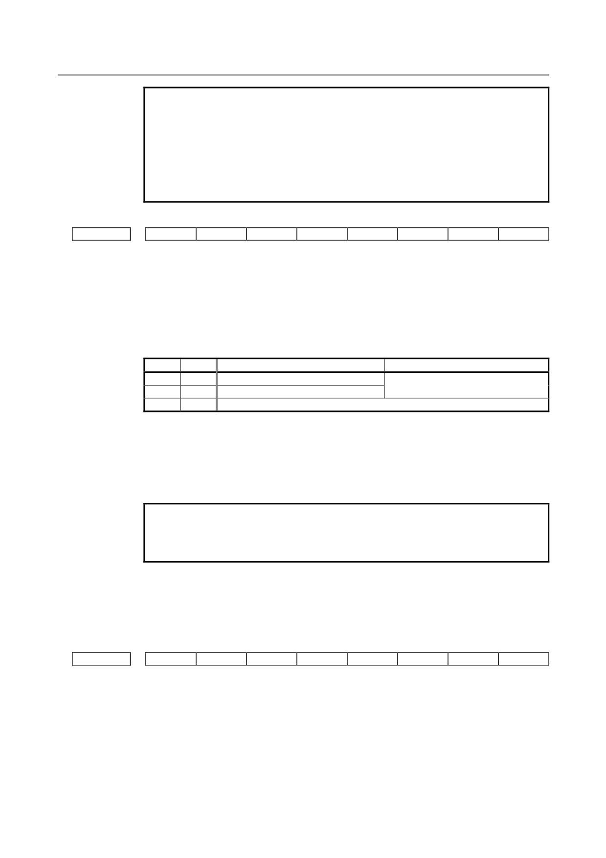
The ASB and ASL bits set the type and time constant of acceleration/deceleration after
interpolation in the skip function as follows:
ASB
ASL
Type of acceleration/ deceleration
Parameter No. for time constant
0
1
Linear type
Parameter No. 6280
1
-
Bell-shaped
0
0
This function is disabled(NOTE).
When bell-shaped acceleration/deceleration is specified, T1=T/2 and T2=T/2 are obtained
as with normal acceleration/deceleration after cutting feed interpolation, where T is the
time constant. Therefore, the acceleration/deceleration type includes no linear part. To
specify
bell-shaped
acceleration/deceleration,
the
option for
bell-shaped
acceleration/deceleration after cutting feed interpolation is required.
NOTE
In this case, the acceleration/deceleration type is set in bits 0 and 1
of parameter No. 1610, and the time constant is set in parameter
No. 1622.
#6 MDC The measurement result of automatic tool length measurement (M series) or automatic
tool compensation (T series) is:
0: Added to the current offset.
1: Subtracted from the current offset.
#7
#6
#5
#4
#3
#2
#1
#0
6215
CSTx
[Input type] Parameter input
[Data type] Bit axis
#0 CSTx On a Cs contour control axis, torque limit skip operation is:
0: Not performed.
1: Performed.
Torque limit skip operation is performed using the torque limit command signal TLMH
and the load detection signal LDT1 of the serial spindle.
- 266 -
B-64310EN/02
4.DESCRIPTION OF PARAMETERS
NOTE
When setting this parameter to carry out a torque limit skip on a Cs
contour control axis, keep the following in mind.
1 Set bit 4 of the serial spindle parameter of the Cs contour control
axis (spindle) that uses the torque limit skip function to 1 so that
the load detection signal is output during
acceleration/deceleration.
2 If the load detection state is entered (LDT1 = "1") when the
torque limit command is executed (TLMH1 = "1") in the Cs
mode, the alarm detection level in the stop state is not checked
on the axis.
3 If the load detection state is entered (LDT1 = "1") in the Cs
mode, an in-position check is not performed on the axis.
6221
Torque limit dead zone time for a torque limit skip command
[Input type] Parameter input
[Data type] 2-word axis
[Unit of data] msec
[Valid data range] 0 to 65535
The torque limit skip arrival signal is ignored for a set period of time.
If G31P98 is specified, skip operation is not performed for a set period of time after the
torque limit skip arrival signal is set to 1.
If G31P99 is specified, skip operation is not performed for a set period of time after the
torque limit skip arrival signal is set to 1.
However, if a skip signal is input, skip operation is performed, regardless of the period of
time set in this parameter.
#7
#6
#5
#4
#3
#2
#1
#0
6240
IGA
AE0
[Input type] Parameter input
[Data type] Bit path
NOTE
When at least one of these parameters is set, the power must be
turned off before operation is continued.
#0 AE0 Measurement position arrival is assumed when the automatic tool compensation signals
XAE1 and XAE2 <X004.0, 1> (T series) or the automatic tool length measurement
signals XAE1, XAE2, and XAE3 <X004.0, .1, .2> (M series) are:
0:
1.
1:
0.
#7 IGA Automatic tool length measurement (M series) or automatic tool compensation (T series)
is:
0: Used.
1: Not used.
- 267 -
4.DESCRIPTION OF PARAMETERS
B-64310EN/02
Feedrate during measurement of automatic tool compensation (T series) (for the XAE1 and GAE1
signals)
6241
Feedrate during measurement of automatic tool length measurement (M series) (for the XAE1 and
GAE1 signals)
Feedrate during measurement of automatic tool compensation (T series) (for the XAE2 and GAE2
signals)
6242
Feedrate during measurement of automatic tool length measurement (M series) (for the XAE2 and
GAE2 signals)
6243
Feedrate during measurement of automatic tool length measurement (M series) (for the XAE3 and
GAE3 signals)
[Input type] Parameter input
[Data type] Real path
[Unit of data] mm/min, inch/min, deg/min (machine unit)
[Min. unit of data] Depend on the increment system of the applied axis
[Valid data range] Refer to the standard parameter setting table (C)
(When the increment system is IS-B, 0.0 to +999000.0)
These parameters set the relevant feedrate during measurement of automatic tool
compensation (T series) or automatic tool length measurement (M series).
NOTE
When the setting of parameter No. 6242 or 6243 is 0, the setting of
parameter No. 6241 is used.
γ value on the X axis during automatic tool compensation (T series)
6251
γ value during automatic tool length measurement (M series) (for the XAE1 and GAE1 signals)
γ value on the Z axis during automatic tool compensation (T series)
6252
γ value during automatic tool length measurement (M series) (for the XAE2 and GAE2 signals)
6253
γ value during automatic tool length measurement (M series) (for the XAE3 and GAE3 signals)
[Input type] Parameter input
[Data type] 2-word path
[Unit of data] mm, inch, deg (machine unit)
[Min. unit of data] Depend on the increment system of the applied axis
[Valid data range] 9 digit of minimum unit of data (refer to standard parameter setting table (A))
(When the increment system is IS-B, -999999.999 to +999999.999)
These parameters set the relevant γ value during automatic tool compensation (T series)
or automatic tool length measurement (M series).
NOTE
1 For the M series, when the setting of parameter No. 6252 or 6253
is 0, the setting of parameter No. 6251 is used.
2 Set a radius value regardless of whether diameter or radius
programming is specified.
- 268 -
B-64310EN/02
4.DESCRIPTION OF PARAMETERS
6254
ε value on the X axis during automatic tool compensation (T series)
ε value during automatic tool length measurement (M series) (for the XAE1 and GAE1 signals)
6255
ε value on the Z axis during automatic tool compensation (T series)
ε value during automatic tool length measurement (M series) (for the XAE2 and GAE2 signals)
6256
ε value during automatic tool length measurement (M series) (for the XAE3 and GAE3 signals)
[Input type] Parameter input
[Data type] 2-word path
[Unit of data] mm, inch, deg (machine unit)
[Min. unit of data] Depend on the increment system of the applied axis
[Valid data range] 9 digit of minimum unit of data (refer to standard parameter setting table (A))
(When the increment system is IS-B, -999999.999 to +999999.999)
These parameters set the relevant ε value during automatic tool compensation (T series)
or automatic tool length measurement (M series).
NOTE
1 For the M series, when the setting of parameter No. 6252 or 6253
is 0, the setting of parameter No. 6251 is used.
2 Set a radius value regardless of whether diameter or radius
programming is specified.
6280
Time constant for acceleration/deceleration after interpolation for the skip function for each axis
[Input type] Parameter input
[Data type] Word axis
[Unit of data] msec
[Valid data range] 0 to 512
This parameter sets a time constant for acceleration/deceleration after interpolation for the
skip function for each axis.
This parameter is valid when bit 3 (ASB) of parameter No. 6210 or bit 4 (ASL) of
parameter No. 6210 is set to 1.
6281
Feedrate for the skip function (G31)
[Input type] Parameter input
[Data type] Real path
[Unit of data] mm/min, inch/min, degree/min (machine unit)
[Min. unit of data] Depend on the increment system of the reference axis
[Valid data range] Refer to the standard parameter setting table (C)
(When the increment system is IS-B, 0.0 to +999000.0)
This parameter sets a feedrate for the skip function (G31). This parameter is valid when
bit 1 (SFP) of parameter No. 6207 is set to 1.
NOTE
For the multi-stage skip function and high-speed skip, see the
description of parameter No. 6282 to No. 6285.
- 269 -
4.DESCRIPTION OF PARAMETERS
B-64310EN/02
6282
Feedrate for the skip function (G31, G31 P1)
6283
Feedrate for the skip function (G31 P2)
6284
Feedrate for the skip function (G31 P3)
6285
Feedrate for the skip function (G31 P4)
[Input type] Parameter input
[Data type] Real path
[Unit of data] mm/min, inch/min, degree/min (machine unit)
[Min. unit of data] Depend on the increment system of the reference axis
[Valid data range] Refer to the standard parameter setting table (C)
(When the increment system is IS-B, 0.0 to +999000.0)
Each of these parameters sets a feedrate for each skip function G code. These parameters
are valid when bit 2 (SFN) of parameter No. 6207 is set to 1.
#7
#6
#5
#4
#3
#2
#1
#0
6286
TQOx
[Input type] Parameter input
[Data type] Bit axis
#0 TQOx The torque limit override function is:
0: Disabled. (Override of 100%)
1: Enabled.
NOTE
Before the torque limit skip function can be used, this parameter
must be set to 1.
6287
Positional deviation limit in torque limit skip
[Input type] Parameter input
[Data type] 2-word axis
[Unit of data] Detection unit
[Valid data range] 0 to 327670
This parameter sets a positional deviation limit for each axis imposed when torque limit
skip is specified. When the actual positional deviation exceeds the positional deviation
limit, the alarm (SV0004) is issued and an immediate stop takes place.
4.35 PARAMETERS OF EXTERNAL DATA INPUT/OUTPUT
#7
#6
#5
#4
#3
#2
#1
#0
6300
EEX
ESR
ESC
[Input type] Parameter input
[Data type] Bit path
#3 ESC When a reset is input between the input of the external data input read signal ESTB and
the execution of a search, the external program number search function:
0: Performs a search.
1: Does not perform a search.
- 270 -
B-64310EN/02
4.DESCRIPTION OF PARAMETERS
#4 ESR The external program number search function is:
0: Disabled.
1: Enabled.
#7 EEX PMC EXIN function
0: Conventional specifications
1: Extended specifications
If you want to use external machine coordinate system shift which handles ±10.000 or
more shift unavailable with the PMC/EXIN command in the conventional specifications,
set 1.
When this function is used for a 2-path system, the setting for path 1 is used.
For details of EXIN and how to change ladder software, refer to the PMC manuals.
#7
#6
#5
#4
#3
#2
#1
#0
6301
EED
NNO
EXM
EXA
[Input type] Parameter input
[Data type] Bit machine group
#0 EXA This bit selects an external alarm message specification.
0: A message number from 0 to 999 can be sent. When displaying an alarm number,
the CNC prefixes the character string "EX" to the alarm number obtained by adding
1000 to the message number.
1: A message number from 0 to 4095 can be sent. The CNC prefixes the character
string "EX" to a alarm number for display.
#1 EXM This bit selects an external operator message specification.
0: A message number from 0 to 999 can be sent. The message of a message number
from 0 to 99 is displayed together with its number. The CNC adds 2000 to a number
for distinction. A message number from 100 to 999 is not displayed on the screen,
but only the corresponding message is displayed on the screen.
1: A message number from 0 to 4095 can be sent. The message of a message number
from 0 to 99 is displayed together with its number. The CNC prefixes the character
string "EX" to a message number for display. A message number from 100 to 4095
is not displayed on the screen, but only the corresponding message is displayed on
the screen.
#2 NNO When operator messages are set by external data input, a new line operation between one
message set with a number and another message set with a different number is:
0: Performed.
1: Not performed.
#3 EED To specify data for external tool compensation and external workpiece coordinate system
shift, use:
0: Signals ED15 to ED0.
(The value which can be specified for tool compensation and workpiece coordinate
system shift is from 0 to ±7999.)
1: Signals ED31 to ED0.
(The value which can be specified for tool compensation and workpiece coordinate
system shift is from 0 to ±79999999.)
- 271 -
4.DESCRIPTION OF PARAMETERS
B-64310EN/02
6310
Setting for number addition to external operator messages
NOTE
When this parameter is set, the power must be turned off before
operation is continued.
[Input type] Parameter input
[Data type] Word machine group
[Valid data range] 0 to 4095
This parameter sets the number of messages to which message numbers are to be prefixed
in external operator message display.
When 0 is set, the same operation as when 100 is set is performed.
[Example] When 500 is set in this parameter, the messages of message numbers 0 to 499 are
displayed together with their numbers on the screen. A message number of 500 and up is
not displayed on the screen, but only the corresponding message is displayed on the
screen.
4.36 PARAMETERS OF MANUAL HANDLE RETRACE (1 OF 2)
#7
#6
#5
#4
#3
#2
#1
#0
MG4
MGO
RVN
HMP
MC8
MC5
FWD
RPO
6400
MG4
MGO
RVN
MC8
MC5
FWD
RPO
[Input type] Parameter input
[Data type] Bit path
#0 RPO With the manual handle retrace function, the rapid traverse rate is clamped, assuming
that:
0: An override of 10% is used.
1: An override of 100% is used.
#1 FWD With the manual handle retrace function, program execution can be performed:
0: In both forward and backward directions.
1: In the forward direction only. Execution in the backward direction is not permitted.
#2 MC5
#3 MC8
These parameters set the number of M code groups and the number of M codes per group.
(See explanations of parameters Nos. 6411 to 6490.)
MC5
MC8
M code group setting
0
0
Standard (20 groups of four)
1
0
16 groups of five
0
1
10 groups of eight
When 16 groups of five are used, the meanings of parameters are changed as follows:
Group A
No.6411(1) to No.6415(5)
Group B
No.6416(1) to No.6420(5)
:
Group P
No.6486(1) to No.6490(5)
When 10 groups of eight are used, they are changed as follows:
Group A
No.6411(1) to No.6418(8)
- 272 -
B-64310EN/02
4.DESCRIPTION OF PARAMETERS
Group B
No.6419(1) to No.6426(8)
:
Group J
No.6483(1) to No.6490(8)
#4 HMP When inversion or backward movement is inhibited in other paths:
0: Inversion or backward movement is not inhibited for the currently executed path.
1: Inversion or backward movement is inhibited also for the currently executed path.
#5 RVN When the manual handle retrace function is used, M codes other than grouped M codes:
0: Do not disable backward movement.
1: Disable backward movement.
When this parameter is set to 1, M codes other than grouped M codes disable backward
movement in general. Exceptionally, however, the following M codes allow backward
movement:
1.
Subprogram call based on M98/M99
2.
Subprogram call based on an M code
3.
Macro call based on an M code
4.
Waiting M code
5.
M0
#6 MGO When the manual handle retrace function is used, handle pulses during execution of a G
code related to measurement are:
0: Valid.
1: Invalid. A speed with an override of 100% is used for execution at all times.
#7 MG4 In the manual handle retrace function, for blocks for which multi-step skip G04 is enabled
(when the multi-step skip software option is used, and the settings of parameter Nos.
6202 to 6206 are valid):
0: Backward movement is not prohibited.
1: Backward movement is prohibited.
#7
#6
#5
#4
#3
#2
#1
#0
6401
STO
HST
CHS
[Input type] Parameter input
[Data type] Bit path
#2 CHS In manual handle retrace:
0: The status is displayed if the following conditions are all satisfied:
(1) Bit
6 (HST) of parameter No. 6401, which specifies whether to enable or
disable status display, is set to 1.
(2) Check mode output signal MMMOD<Fn091.3> is set to 1.
1: The status is displayed if the following conditions are all satisfied:
(1) Bit
6 (HST) of parameter No. 6401, which specifies whether to enable or
disable status display, is set to 1.
(2) Cycle start lamp signal STL<Fn000.5> is set to 1.
(3) Check mode input signal MMOD<Gn067.2> is set to 1.
(4) Handle input signal MCHK<Gn067.3> is set to 1 in the check mode.
#6 HST When the manual handle retrace function is used, the time display field on the status
display line of the CNC screen:
0: Does not display status.
1: Displays status.
- 273 -

4.DESCRIPTION OF PARAMETERS
B-64310EN/02
#7 STO In the manual handle retrace function, the timing for outputting an S code and T code
during backward movement is:
0: Different from the timing during forward movement:
1: The same as during forward movement.
#7
#6
#5
#4
#3
#2
#1
#0
6402
MWR
[Input type] Parameter input
[Data type] Bit path
#5 MWR When the manual handle retrace function is used, for a handle operation placed in the
wait state by a wait M code during backward movement:
0: Inversion is prohibited.
1: Inversion is permitted.
Override value (equivalence) for clamping the rapid traverse rate used with the manual handle retrace
6405
function
[Input type] Parameter input
[Data type] Word path
[Unit of data] %
[Valid data range] 0 to 100
This parameter sets an override value (equivalence) for clamping the rapid traverse rate
used with the manual handle retrace function. If a value greater than 100 is set in
parameter (No.6405), the rapid traverse rate is clamped to an override of 100%. This
function is invalid if 0 is set in parameter (No.6405). In this case, the setting of bit 0
(RPO) of parameter No. 6400 is used.
6410
Travel distance per pulse generated from the manual pulse generator
[Input type] Parameter input
[Data type] Word path
[Unit of data] %
[Valid data range] 0 to 100
Set the travel distance per pulse generated from the manual pulse generator in terms of
the override value.
The distance traveled by the machine when the manual handle is actually turned can be
found by the following expression:
[Specified speed]
× [Handle magnification]
× ([Setting of this parameter]/100)
×
(8/60000) (mm or inch)
[Example] When a specified feedrate is 30mm/min, the manual handle magnification is 100, and
parameter No. 6410 is set to 1, the travel distance per pulse generated from the manual
pulse generator is calculated as follows:
[Travel distance per pulse]=30[mm/min] × 100 × (1/100) × (8/60000)[min]= 0.004mm
6411
M code of group A in manual handle retrace (1)
to
6414
M code of group A in manual handle retrace (4)
6415
M code of group B in manual handle retrace (1)
to
6418
M code of group B in manual handle retrace (4)
- 274 -

B-64310EN/02
4.DESCRIPTION OF PARAMETERS
6419
M code of group C in manual handle retrace (1)
to
6422
M code of group C in manual handle retrace (4)
6423
M code of group D in manual handle retrace (1)
to
6426
M code of group D in manual handle retrace (4)
6427
M code of group E in manual handle retrace (1)
to
6430
M code of group E in manual handle retrace (4)
6431
M code of group F in manual handle retrace (1)
to
6434
M code of group F in manual handle retrace (4)
6435
M code of group G in manual handle retrace (1)
to
6438
M code of group G in manual handle retrace (4)
6439
M code of group H in manual handle retrace (1)
to
6442
M code of group H in manual handle retrace (4)
6443
M code of group I in manual handle retrace (1)
to
6446
M code of group I in manual handle retrace (4)
6447
M code of group J in manual handle retrace (1)
to
6450
M code of group J in manual handle retrace (4)
6451
M code of group K in manual handle retrace (1)
to
6454
M code of group K in manual handle retrace (4)
6455
M code of group L in manual handle retrace (1)
to
6458
M code of group L in manual handle retrace (4)
6459
M code of group M in manual handle retrace (1)
to
6462
M code of group M in manual handle retrace (4)
6463
M code of group N in manual handle retrace (1)
to
6466
M code of group N in manual handle retrace (4)
6467
M code of group O in manual handle retrace (1)
to
6470
M code of group O in manual handle retrace (4)
6471
M code of group P in manual handle retrace (1)
to
6474
M code of group P in manual handle retrace (4)
- 275 -
4.DESCRIPTION OF PARAMETERS
B-64310EN/02
6475
M code of group O in manual handle retrace (1)
to
6478
M code of group Q in manual handle retrace (4)
6479
M code of group R in manual handle retrace (1)
to
6482
M code of group R in manual handle retrace (4)
6483
M code of group S in manual handle retrace (1)
to
6486
M code of group S in manual handle retrace (4)
6487
M code of group T in manual handle retrace (1)
to
6490
M code of group T in manual handle retrace (4)
[Input type] Parameter input
[Data type] 2-word path
[Valid data range] 0 to 9999
Set a group of M codes output during backward movement.
For backward movement for an M code, the modal M code in the same group set by the
parameter is output.
The first M code in each group is set as the default.
When the number of M codes in a group is 3 or less, set the parameter corresponding to
an unused M code to 0.
For backward movement for "M0", "M0" is output regardless of which M code is set for
the parameter. "0" set in the parameter is ignored.
For an M code which is not set in any group by any of the above parameters, the M code
for forward movement is output.
With these parameters, an M code in the same group can be output in backward
movement only when the M code is the first M code in each block. When a block
contains two or more M codes, the same M codes as output in forward movement are
output as a second M code and up.
NOTE
The above explanation of M code groups applies to the standard
settings. The number of M codes in each group and the number of
M code groups vary depending on the settings of bit 2 (MC5) and
bit 3 (MC8) of parameter No. 6400.
4.37
PARAMETERS OF GRAPHIC DISPLAY (1 OF 3)
#7
#6
#5
#4
#3
#2
#1
#0
DPA
SPC
6500
[Input type] Parameter input
[Data type] Bit
#1 SPC Graphic display in 2-path control includes:
0: Two spindles and two tool posts.
1: One spindle and two tool posts.
- 276 -
B-64310EN/02
4.DESCRIPTION OF PARAMETERS
NOTE
This parameter is valid when two paths are displayed at the same
time.
#3 DPA The current position display on the graphic display screen displays:
0: The actual position with tool-nose radius compensation considered.
1: The programmed position.
#7
#6
#5
#4
#3
#2
#1
#0
CSR
6501
CSR
3PL
ORG
[Input type] Parameter input
[Data type] Bit path
#0 ORG When the coordinate system is changed during tool path drawing by the dynamic graphic
display function, drawing is performed:
0: With the same coordinate system.
1: With the current drawing point assumed to be the current position set in the new
coordinate system.
NOTE
This parameter is valid when bit 3 (BGM) of parameter No. 11329
is 0.
#2
3PL In animated simulation of the dynamic graphic display function, triplane drawing is
drawn:
0: In third angle projection.
1: In first angle projection.
#5 CSR On the PATH GRAPHIC (CURRENT POSITION) screen, the shape of the cursor
indicating the tool position is:
0: A square (Ŷ).
1: An x (×).
Drawing coordinate system for one-spindle graphic (2-path control)
6509
[Input type] Parameter input
[Data type] Byte
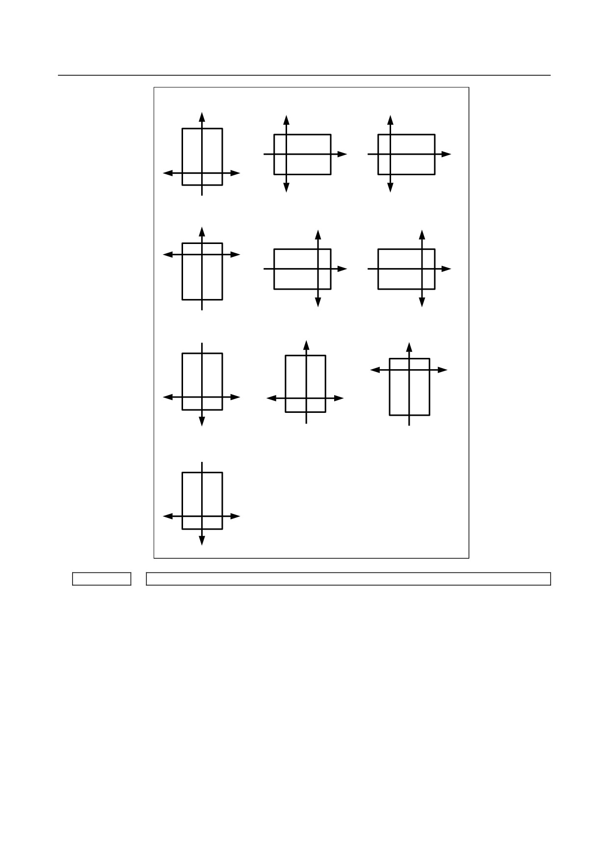
[Valid data range] 0 to 9, 10 to 19 (however, a setting of 0 to 9 is the same as that of 10 to 19, respectively.)
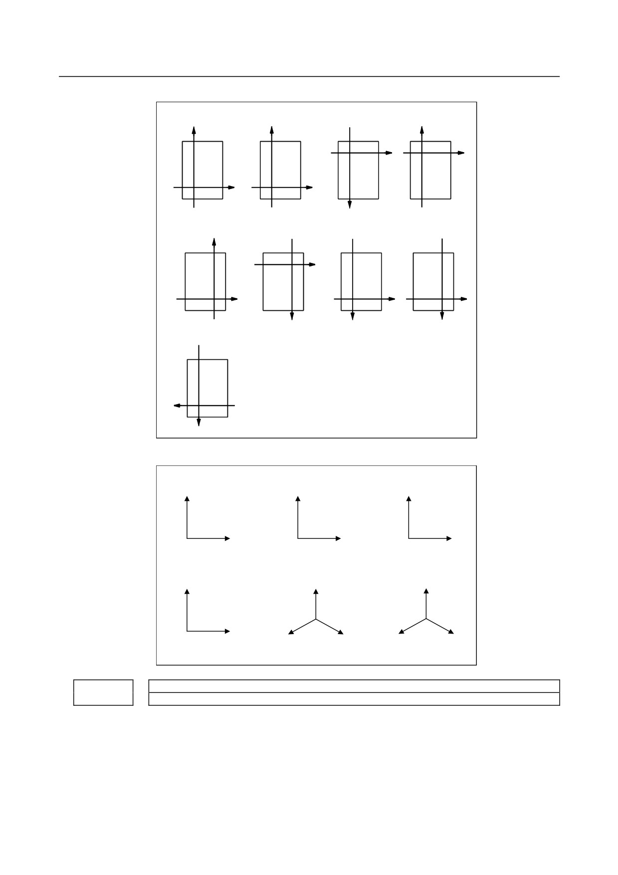
This parameter sets the drawing coordinate system for one-spindle graphic (bit 1 (SPC) of
parameter No. 6500 is 1) in 2-path control.
The drawing coordinate system is set as shown below.
- 277 -
4.DESCRIPTION OF PARAMETERS
B-64310EN/02
Setting =0 or 10
Setting =1 or 11
Setting =2 or 12
Z
X1
X2
Z
Z
X2
X1
X2
X1
Setting =3 or 13
Setting =4 or 14
Setting =5 or 15
Z
X1
X2
X2
X1
Z
Z
X2
X1
Setting =6 or 16
Setting =7 or 17
Setting =8 or 18
Z
Z
X1
X2
X2
X1
X1
X2
Z
Setting =9 or 19
X1
X2
Z
6510
Drawing coordinate system
[Input type] Parameter input
[Data type] Byte path
[Valid data range] 0 to 8
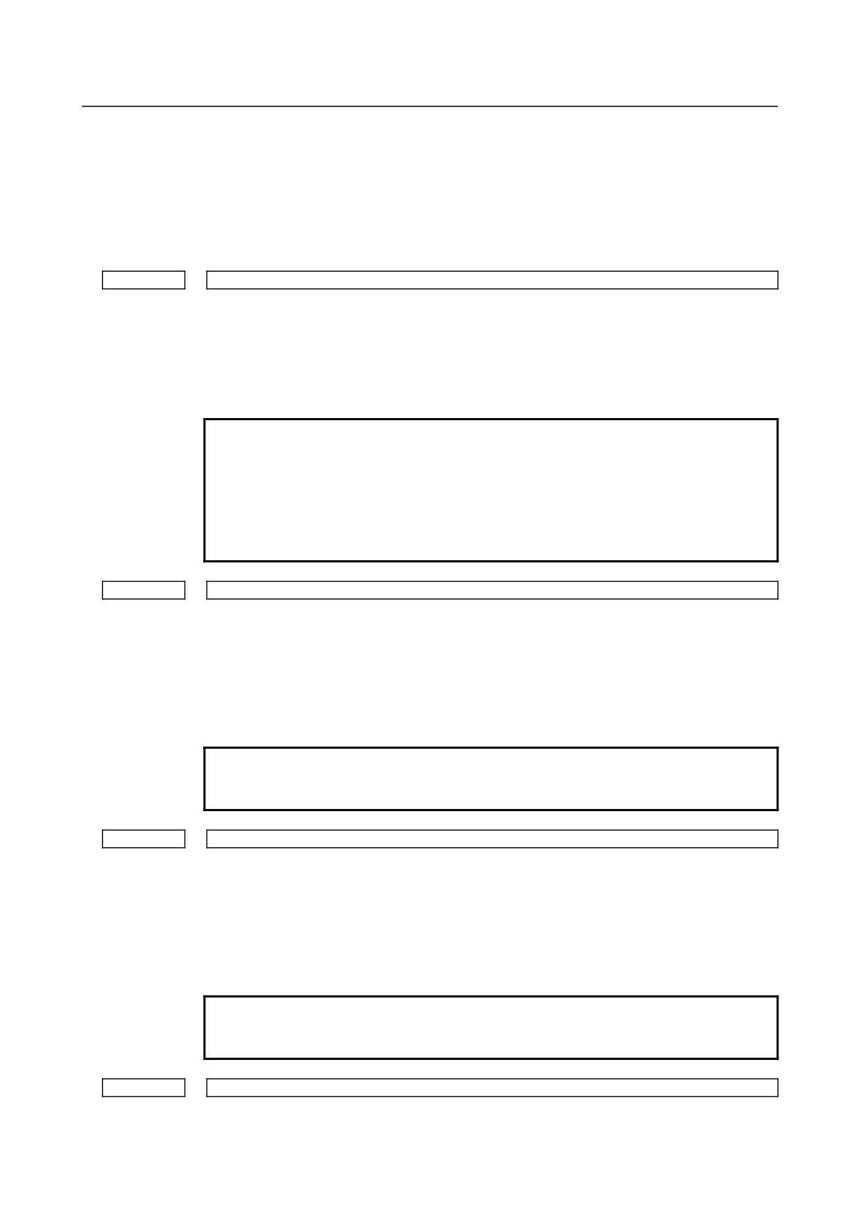
This parameter sets the drawing coordinate system for the graphic display function.
The drawing coordinate system is set as shown below.
- 278 -
B-64310EN/02
4.DESCRIPTION OF PARAMETERS
For T series:
Setting =1
Setting =1
Setting =2
Setting =3
Z
X
Z
Z
X
X
Z
X
Setting =4
Setting =5
Setting =6
Setting =7
X
Z
Z
X
Z
X
Z
X
Setting =8
X
Z
For M series:
Setting = 0 (XY)
Setting = 1 (YZ)
Setting = 2 (ZY)
Y
Z
Y
X
Y
Z
Setting = 3 (XZ)
Setting = 4 (XYZ)
Setting = 5 (ZXY)
Z
Z
Y
X
X
Y
Z
X
6515
Change in the cross-sectional position in a triplane drawing in dynamic graphic display
[Input type] Parameter input
[Data type] Byte path
[Unit of data] Dot
[Valid data range] 0 to 10
This parameter sets changes in the cross-sectional position in a triplane drawing in
dynamic graphic display, which are made when the soft key is pressed and held.
A setting of 0 is assumed to be 1.
- 279 -

4.DESCRIPTION OF PARAMETERS
B-64310EN/02
4.38
PARAMETERS OF SCREEN DISPLAY COLORS (1 OF 2)
6581
RGB value of color palette 1
6582
RGB value of color palette 2
6583
RGB value of color palette 3
6584
RGB value of color palette 4
6585
RGB value of color palette 5
6586
RGB value of color palette 6
6587
RGB value of color palette 7
6588
RGB value of color palette 8
6589
RGB value of color palette 9
6590
RGB value of color palette 10
6591
RGB value of color palette 11
6592
RGB value of color palette 12
6593
RGB value of color palette 13
6594
RGB value of color palette 14
6595
RGB value of color palette 15
[Input type] Parameter input
[Data type] 2-word
[Valid data range] 0 to 151515
Each of these parameters sets the RGB value of each color palette by specifying a 6-digit
number as described below.
rrggbb: 6-digit number (rr: red data, gg: green data, bb: blue data)
The valid data range of each color is 0 to 15 (same as the tone levels on the color setting
screen). When a number equal to or greater than 16 is specified, the specification of 15 is
assumed.
[Example] When the tone level of a color is: red:1 green:2, blue:3, set 10203 in the parameter.
4.39 PARAMETERS OF RUN HOUR AND PARTS COUNT
DISPLAY
#7
#6
#5
#4
#3
#2
#1
#0
6700
PRT
PCM
[Input type] Parameter input
[Data type] Bit path
- 280 -
B-64310EN/02
4.DESCRIPTION OF PARAMETERS
#0 PCM M code that counts the total number of machined parts and the number of machined parts
0: M02, or M30, or an M code specified by parameter No.6710
1: Only M code specified by parameter No.6710
#1 PRT Upon reset, the required parts count arrival signal (PRTSF) is:
0: Set to "0".
1: Not set to "0".
6710
M code that counts the number of machined parts
[Input type] Parameter input
[Data type] 2-word path
[Valid data range] 0 to 99999999
The total number of machined parts and the number of machined parts are counted (+1)
when the M code set is executed.
NOTE
The setting of 0 is invalid (no count operation is performed with
M00.) Moreover, M98, M99, M198 (external device subprogram
calling), and M codes used for subprogram calling and macro
calling cannot be set as M codes for count-up operation. (Even
when such an M code is set, count-up operation is not performed,
ignoring the M code.)
6711
Number of machined parts
[Input type] Setting input
[Data type] 2-word path
[Valid data range] 0 to 999999999
The number of machined parts is counted (+1) together with the total number of
machined parts when the M02, M30, or a M code specified by parameter No.6710 is
executed.
NOTE
The number of parts is not counted for M02, M03, when bit 0
(PCM) of parameter No. 6700 is set to 1.
6712
Total number of machined parts
[Input type] Setting input
[Data type] 2-word path
[Valid data range] 0 to 999999999
This parameter sets the total number of machined parts.
The total number of machined parts is counted (+1) when M02, M30, or an M code
specified by parameter No.6710 is executed.
NOTE
The number of parts is not counted for M02, M30, when bit 0
(PCM) of parameter No. 6700 is set to 1.
6713
Number of required parts
[Input type] Setting input
- 281 -

4.DESCRIPTION OF PARAMETERS
B-64310EN/02
[Data type] 2-word path
[Valid data range] 0 to 999999999
This parameter sets the number of required machined parts.
Required parts finish signal PRTSF <F0062.7> is output to PMC when the number of
machined parts reaches the number of required parts. The number of parts is regarded as
infinity when the number of required parts is zero. The PRTSF signal is then not output.
6750
Integrated value of power-on period
[Input type] Parameter input
[Data type] 2-word path
[Unit of data] min
[Valid data range] 0 to 999999999
This parameter displays the integrated value of power-on period.
6751
Operation time (integrated value of time during automatic operation) 1
[Input type] Setting input
[Data type] 2-word path
[Unit of data] msec
[Valid data range] 0 to 59999
For details, see the description of parameter No. 6752.
6752
Operation time (integrated value of time during automatic operation) 2
[Input type] Setting input
[Data type] 2-word path
[Unit of data] min
[Valid data range] 0 to 999999999
This parameter displays the integrated value of time during automatic operation (neither
stop nor hold time included).
The actual time accumulated during operation is the sum of this parameter No. 6751 and
parameter No. 6752.
6753
Integrated value of cutting time 1
[Input type] Setting input
[Data type] 2-word path
[Unit of data] msec
[Valid data range] 0 to 59999
For details, see the description of parameter No. 6754.
6754
Integrated value of cutting time 2
[Input type] Setting input
[Data type] 2-word path
[Unit of data] min
[Valid data range] 0 to 999999999
This parameter displays the integrated value of a cutting time that is performed in cutting
feed such as linear interpolation (G01) and circular interpolation (G02 or G03).
The actual time accumulated during cutting is the sum of this parameter No. 6753 and
parameter No. 6754.
- 282 -
B-64310EN/02
4.DESCRIPTION OF PARAMETERS
6755
Integrated value of general-purpose integrating meter drive signal (TMRON) ON time 1
[Input type] Setting input
[Data type] 2-word path
[Unit of data] msec
[Valid data range] 0 to 59999
For details, see the description of parameter No. 6756.
6756
Integrated value of general-purpose integrating meter drive signal (TMRON) ON time 2
[Input type] Setting input
[Data type] 2-word path
[Unit of data] min
[Valid data range] 0 to 999999999
This parameter displays the integrated value of a time while input signal TMRON
<G0053.0> from PMC is on.
The actual integrated time is the sum of this parameter No. 6755 and parameter No. 6756.
6757
Operation time (integrated value of one automatic operation time) 1
[Input type] Setting input
[Data type] 2-word path
[Unit of data] msec
[Valid data range] 0 to 59999
For details, see the description of parameter No. 6758.
6758
Operation time (integrated value of one automatic operation time) 2
[Input type] Setting input
[Data type] 2-word path
[Unit of data] min
[Valid data range] 0 to 999999999
This parameter displays the one automatic operation drive time (neither stop nor hold
state included). The actual time accumulated during operating is the sum of this parameter
No. 6757 and parameter No. 6758. The operation time is automatically preset to 0 during
the power-on sequence and the cycle start from the reset state.
4.40 PARAMETERS OF TOOL LIFE MANAGEMENT (1 OF 2)
#7
#6
#5
#4
#3
#2
#1
#0
6800
M6T
IGI
SNG
GRS
SIG
LTM
GS2
GS1
[Input type] Parameter input
[Data type] Bit path
#0 GS1
#1 GS2 For the maximum number of groups set in parameter No. 6813, up to four tools can be
registered per group. The combination of the number of registrable groups and the
number of tools per group can be changed by setting GS1 and GS2.
GS2
GS1
Number of groups
Number of tools
0
0
1 to maximum number of groups (No. 6813)/8
1 to 16
0
1
1 to maximum number of groups (No. 6813)/4
1 to 8
1
0
1 to maximum number of groups (No. 6813)/2
1 to 4
- 283 -
4.DESCRIPTION OF PARAMETERS
B-64310EN/02
GS2
GS1
Number of groups
Number of tools
1
1
1 to maximum number of groups (No. 6813)
1 to 2
NOTE
After changing these parameters, set data again by using G10
L3 ;(registration after deletion of data of all groups).
#2 LTM The tool life count is specified by:
0: Count.
1: Duration.
NOTE
After changing this parameter, set data again by using G10
L3 ;(registration after deletion of data of all groups).
#3 SIG When a tool is skipped by a signal, the group number is:
0: Not input by the tool group number selection signals.
1: Input by the tool group number selection signals.
NOTE
When this parameter is set to 0, a tool of the currently used group is
skipped.
#4 GRS When the tool change reset signal (TLRST) is input:
0: If the life of the group specified by the tool group number selection signals has
expired, the execution data of the group is cleared.
1: The execution data of all registered groups is cleared.
If this parameter is set to 1, the execution data of all registered groups is cleared also
when the clear operation to clear execution data is performed on the tool life management
list screen.
#5 SNG When the tool skip signal (TLSKP) is input while a tool not controlled by the tool life
management function is being used:
0: A tool of the most recently used group or a specified group (bit 3 (SIG) of parameter
No. 6800) is skipped.
1: The tool skip signal is ignored.
#6 IGI Tool back numbers are:
0: Not ignored.
1: Ignored.
#7 M6T A T code specified in the same block as M06 is:
0: Assumed to be a back number.
1: Assumed to be a command specifying the next tool group.
#7
#6
#5
#4
#3
#2
#1
#0
M6E
EMD
LVF
TSM
6801
M6E
EMD
LVF
[Input type] Parameter input
[Data type] Bit path
- 284 -
B-64310EN/02
4.DESCRIPTION OF PARAMETERS
#1 TSM In the tool life management function, life counting is performed as follows when more
than one offset is specified:
0: Counting is performed for each tool number.
1: Counting is performed for each tool.
#2 LVF When the life value is counted by duration in the tool life management function, tool life
count override signals *TLV0 to *TLV9 <G049.0 to G050.1> are:
0: Not used.
1: Used.
#3 EMD In the tool life management function, the mark "*" indicating that the life has expired is
displayed when:
0: The next tool is used.
1: The life has just expired.
NOTE
If this parameter is set to 0, the "@" mark (indicating that the tool is
in use) is kept displayed unless the next tool whose life has not
expired is used. If this parameter is set to 1, marks are displayed in
different ways depending on the life count type.
If the life count type is the duration specification type, the "*" mark
(indicating that the life has expired) appears when the life has
expired. If the life count type is the count specification type, one
count is not assumed until the end of the program (M02, M30, and so
on). Therefore, even when the life value and the tool life counter
value match, the "*" mark (life has expired) does not appear. The "*"
mark (life has expired) appears when the tool is used again by a tool
group command (T code) or tool change command (M06) issued
after the CNC is reset.
#7
M6E When a T code is specified in the same block as M06:
0: The T code is treated as a back number or the group number to be selected next.
Which number is assumed depends on the setting of bit 7 (M6T) of parameter No.
6800.
1: Life counting for the tool group starts immediately.
#7
#6
#5
#4
#3
#2
#1
#0
RMT
TSK
E17
TCO
T99
6802
RMT
TSK
E17
TCO
T99
[Input type] Parameter input
[Data type] Bit path
#0 T99 When M99 of the main program is executed, and there is a the life was expired tool
group:
0: The tool change signal is not output.
1: The tool change signal is output, and the automatic operation becomes a stopped
state..
If the life count is specified by use count and this parameter 1, the tool change signal
TLCH <Fn064.0> is output and the automatic operation becomes a stopped state if the
life of at least one tool group has expired when the M99 command is specified.
- 285 -
4.DESCRIPTION OF PARAMETERS
B-64310EN/02
If the life count type is the duration specification type, the automatic operation becomes a
stopped state if the life of at least one tool group has expired when the M99 command is
specified.
M
If the life count is specified by use count, after the M99 command is specified, a tool
group command (T code) selects, from a specified group, a tool whose life has not
expired, and the next tool change command (M06) increments the tool life counter by
one.
T
If the life count is specified by use count, when a tool group command (T code) is
specified after the M99 command is specified, a tool whose life has not expired is
selected from a specified group, and the tool life counter is incremented by one.
#1 TCO
#2
E17
Specifies whether to allow the FOCAS2 or PMC window function to write tool
information of a group being used or a group to be used next during automatic operation
(the OP signal is set to "1").
6802#1(TCO)
1
Condition
0
6802#2(E17)
1
0
During
Group being used or to be
Tool being used
×
○
automatic
used next
Tool not being used
×
○
○
operation
Group neither being used nor to be used next
○
○
○
Not during automatic operation
○
○
○
ż: Tool information can be written from FOCAS2 and PMC window.
×: Tool information cannot be written from FOCAS2 and PMC window.
When an attempt is made to write tool information from PMC window, completion
code 13 (REJECT ALARM) is returned.
:
Tool information cannot be cleared.
NOTE
When tool information of a tool being used (marked with "@") in the
group being used or to be used next or tool information of the most
recently used tool (marked with "@") in a group that is neither the
group being used nor the group to be used next is cleared, the life
counter is reset to 0.
It is possible to modify tool information of a tool in the group to be
used next. However, because tool selection is already completed,
the selected tool does not change even when the tool information is
modified.
This parameter has no influence on modifications to tool information
by edit operations from the tool life management screen.
#6
TSK If the count type in tool life management is the duration type, then when the last tool of a
group is skipped by a signal:
0: The count value for the last tool equals the life value.
1: The count value for the last tool remains unchanged.
- 286 -

B-64310EN/02
4.DESCRIPTION OF PARAMETERS
#7 RMT Tool life arrival notice signal TLCHB is turned on and off as follows:
0: The signal is turned on if the remaining life value (the life value minus the life
counter value) is smaller than or equal to the remaining life setting. The signal is
turned off if the remaining life value (the life value minus the life counter value) is
greater than the remaining life setting.
1: The signal is turned on if the remaining life value (the life value minus the life
counter value) is equal to the remaining life setting. The signal is turned off if the
remaining life value (the life value minus the life counter value) is not equal to the
remaining life setting.
NOTE
When using the life count override feature, set bit 7 (RMT) of
parameter No. 6802 to 0. When the life count is specified by duration,
the unit used for determining the result of comparison between the
remaining life and the remaining life setting varies depending on the
life count interval (bit 0 (FCO) of parameter No. 6805). If the life is
counted every second, the comparison is made in units of 1 minute; if
the life is counted every 0.1 second, the comparison is made in units
of 0.1 minute.
#7
#6
#5
#4
#3
#2
#1
#0
6804
LFI
ETE
TCI
[Input type] Parameter input
[Data type] Bit path
#1 TCI During automatic operation (the OP signal is "1"), editing of tool life data is:
0: Disabled.
1: Enabled.
NOTE
When this parameter is set to 1, tool life data can be edited even
during automatic operation (the OP signal is "1"). If the target group
for editing is the group being used or the group to be used next,
however, only presetting of the life counter is permitted, and other
data cannot be modified.
#2 ETE In the tool life management screen, the mark of the tool at the life was expired of the final
tool in the group :
0: depends on setting parameter EMD (No.6801#3).
1: is "*" mark.
If bit 2 (ETE) of parameter No. 6804 is set to 1, when the life counter of the final tool in
the group becomes equal to the life value, display mark "*" in the final tool of the tool life
management screen.
When tool change signal TLCH<Fn064.0> is "1", the state of the life was expired of the
tool can be read by reading tool information on the final tool in FOCAS2 or the PMC
window.
#6 LFI In tool life management, counting of the life of a selected tool is:
0: Enabled.
1: Enabled or disabled according to the status of tool life counting disable signal
LFCIV<G048.2>.
- 287 -
4.DESCRIPTION OF PARAMETERS
B-64310EN/02
#7
#6
#5
#4
#3
#2
#1
#0
6805
TAD
TRU
TRS
FGL
FCO
[Input type] Parameter input
[Data type] Bit path
#0 FCO If the life count type is the duration specification type, the life is counted as follows:
0: Every second.
1: Every 0.1 second.
According to the setting of this parameter, the increment system of life values and tool
life counter values displayed on the tool life management screen is set as follows:
Parameter FCO
0
1
Increment system for display and setting of life values and
1-minute
0.1-minute
life counter values
increments
increments
NOTE
After changing the setting of this parameter, set data again by using
G10L3;(registration after deletion of data of all groups).
#1 FGL If the life count type is the duration specification type, life data registered by G10 is:
0: In one-minute increments.
1: In 0.1-second increments.
#5 TRS Tool change reset signal TLRST is valid when reset signal RST is not "1" and:
0: The reset state (automatic operation signal OP is "0") is observed.
1: The reset state (automatic operation signal OP is "0"), automatic operation stop state
(The STL and SPL signals are "0" and the OP signal is "1"), or the automatic
operation pause state (the STL signal is "0" and the SPL signal is "1") is observed.
The TLRST signal, however, is invalid when the automatic operation stop state,
automatic operation pause state, and automatic operation start state (the STL signal
is "1") is observed during execution of a data setting command (G10L3).
#6 TRU When the life count type is the duration specification type, and the life is counted every
second (bit 0 (FCO) of parameter No. 6805 is set to 0):
0: Cutting time less than one second is discarded and is not counted.
1: Cutting time less than one second is rounded up and is counted as one second.
NOTE
If the life is counted every 0.1 second (bit 0 (FCO) of parameter No.
6805 is set to 1), cutting time less than 0.1 second is always rounded
up and is counted as 0.1 second.
#7 TAD With tool change type D (bit 7 (M6E) of parameter No. 6801 is set to 1), when a block
specifying M06 contains no T command:
0: An alarm PS0153 is issued.
1: No alarm is issued.
6810
Tool life management ignore number
[Input type] Parameter input
[Data type] 2-word path
[Valid data range] 0 to 99999999
- 288 -
B-64310EN/02
4.DESCRIPTION OF PARAMETERS
This parameter sets the tool life management ignore number.
When the value specified in a T code exceeds the value set in this parameter, the value
obtained by subtracting the parameter-set value from the T code value is assumed to be
the tool group number for tool life management.
6811
Tool life count restart M code
[Input type] Parameter input
[Data type] Byte path
[Valid data range] 0 to 127 (except 01, 02, 30, 98, and 99)
When 0 is specified, it is ignored.
When the life is specified by count, the tool change signal (TLCH) is output if the life of
at least one tool group has expired when the tool life count restart M code is issued.
The T code (tool life management group command) specified after the tool life count
restart M code selects a tool whose life has not expired from a specified group, and the
next M06 command increments the tool life counter by one.
When the life is specified by duration, specifying the tool life count restart M code causes
nothing. When 0 is set in this parameter, the tool life count restart M code is invalid.
When the data of M code exceeds 127 values, set 0 in parameter No.6811, and set the
value of M code in parameter No.13221. The data range of parameter No.13221 is from 0
to 255.
6813
Maximum number of groups in tool life management
NOTE
When this parameter is set, the power must be turned off before
operation is continued.
[Input type] Parameter input
[Data type] Word path
[Unit of data] Group
[Valid data range] 0, 8, 16 to 128
This parameter sets the maximum number of groups to be used for each path. As the
maximum number of groups, set a multiple of eight. When this parameter is 0, 128
groups are set. Up to 128 groups can be set for each path.
NOTE
If the power is turned on after this parameter is changed, all data in
the tool life management file is initialized. Therefore, the life
management data of all paths that use the tool life management
function must be set.
6844
Remaining tool life (use count)
[Input type] Parameter input
[Data type] Word path
[Valid data range] This range is the same as the tool life range.
This parameter sets a remaining tool life (use count) used to output the tool life arrival
notice signal when the tool life is specified by use count. If a value greater than the tool
life value or 0 is set in this parameter, the tool life arrival notice signal is not output.
- 289 -
4.DESCRIPTION OF PARAMETERS
B-64310EN/02
6845
Remaining tool life (use duration)
[Input type] Parameter input
[Data type] 2-word path
[Unit of data] min
[Valid data range] Not greater than the tool life value
This parameter sets the remaining tool life (use duration) used to output the tool life
arrival notice signal when the tool life is specified by use duration. If a value greater than
the tool life value or 0 is specified in this parameter, the tool life arrival notice signal is
not output.
NOTE
When the life is counted every 0.1 second (bit 0 (FCO) of parameter
No. 6805 = 1), the parameter value is in 0.1-minute increments.
6846
Number of remaining group tools
[Input type] Parameter input
[Data type] Byte path
[Valid data range] 0 to 127
This parameter sets the number of remaining group tools.
If the number of remaining tools in the group selected by the T code command is equal to
or less than the setting of this parameter, tool remaining count notification signal TLAL is
output. When this parameter is set to 0, tool remaining count notification signal TLAL
is not output.
4.41 PARAMETERS OF POSITION SWITCH FUNCTIONS
#7
#6
#5
#4
#3
#2
#1
#0
6901
PSA
EPW
[Input type] Parameter input
[Data type] Bit path
#1 EPW The maximum number of points of the position switch is:
0:
10.
1:
16.
#2 PSA In determination of a position switch function operation range, a servo delay amount
(positional deviation) and a delay amount in acceleration/deceleration control are:
0: Not considered.
1: Considered.
6910
Controlled axis for which the 1st position switch function is performed
to
to
6925
Controlled axis for which the 16-th position switch function is performed
[Input type] Parameter input
[Data type] Byte path
[Valid data range] 0 to Number of controlled axes
- 290 -
B-64310EN/02
4.DESCRIPTION OF PARAMETERS
Set the controlled axis number corresponding to one of the first to sixteenth position
switch functions. When the machine coordinate of the corresponding axis is within a
parameter-set range, the corresponding position switch signal is output to the PMC.
NOTE
The setting of 0 means that the position switch function is not used.
6930
Maximum value of the operating range of the 1st position switch
to
to
6945
Maximum value of the operating range of the 16-th position switch
[Input type] Parameter input
[Data type] Real path
[Unit of data] mm, inch, degree (machine unit)
[Min. unit of data] Depend on the increment system of the reference axis
[Valid data range] 9 digit of minimum unit of data (refer to standard parameter setting table (A))
(When the increment system is IS-B, -999999.999 to +999999.999)
Set the maximum value of the operating range of the first to sixteenth position switches.
NOTE
1 For a diameter-specified axis, use diameter values to specify the
parameters used to set the maximum and minimum values of an
operating range.
2 The position switch function is enabled upon completion of
reference position return.
3 The parameter No.6940 to No.6945 is effective when bit 1 (EPW)
of parameter No.6901 is set to 1.
6950
Minimum value of the operating range of the 1st position switch
to
to
6965
Minimum value of the operating range of the 16-th position switch
[Input type] Parameter input
[Data type] Real path
[Unit of data] mm, inch, degree (machine unit)
[Min. unit of data] Depend on the increment system of the reference axis
[Valid data range] 9 digit of minimum unit of data (refer to standard parameter setting table (A))
(When the increment system is IS-B, -999999.999 to +999999.999)
Set the minimum value of the operating range of the first to sixteenth position switches.
NOTE
1 For a diameter-specified axis, use diameter values to specify the
parameters used to set the maximum and minimum values of an
operating range.
2 The position switch function is enabled upon completion of
reference position return.
3 The parameter No.6960 to No.6965 is effective when bit 1 (EPW)
of parameter No.6901 is set to 1.
- 291 -
4.DESCRIPTION OF PARAMETERS
B-64310EN/02
4.42 PARAMETERS OF MANUAL OPERATION AND
AUTOMATIC OPERATION
#7
#6
#5
#4
#3
#2
#1
#0
7001
ABS
MIT
[Input type] Parameter input
[Data type] Bit path
#0 MIT The manual intervention/recovery function is:
0: Disabled.
1: Enabled.
#1 ABS For the move command after manual intervention in the manual absolute on state:
0: Different paths are used in the absolute (G90) and incremental (G91) modes.
1: The same path (path in the absolute mode) is used in the absolute (G90) and
incremental (G91) modes.
#7
#6
#5
#4
#3
#2
#1
#0
7055
BCG
[Input type] Parameter input
[Data type] Bit path
#3 BCG The pre-interpolation bell-shaped acceleration/deceleration time constant change function
in AI contour control mode is:
0: Disabled.
1: Enabled.
7066
Acceleration/deceleration reference speed for the time constant change function of bell-shaped
acceleration/deceleration before interpolation
[Input type] Setting input
[Data type] Real path
[Unit of data] mm/min, inch/min, degree/min (input unit)
[Min. unit of data] Depend on the increment system of the reference axis
[Valid data range] Refer to the standard parameter setting table (C)
(When the increment system is IS-B, 0.0 to +999000.0)
This parameter sets the acceleration/deceleration reference speed of the time constant
change function of the bell-shaped acceleration/deceleration before interpolation in AI
contour control.
4.43 PARAMETERS OF MANUAL HANDLE FEED, HANDLE
INTERRUPTION AND HANDLE FEED IN TOOL AXIAL
DIRECTION
#7
#6
#5
#4
#3
#2
#1
#0
7100
MPX
HCL
THD
JHD
[Input type] Parameter input
- 292 -