FANUC Series 0i-MODEL D, Series 0i Mate-MODEL D. PARAMETER MANUAL - page 11
B-64310EN/02
4.DESCRIPTION OF PARAMETERS
[Data type] Bit path
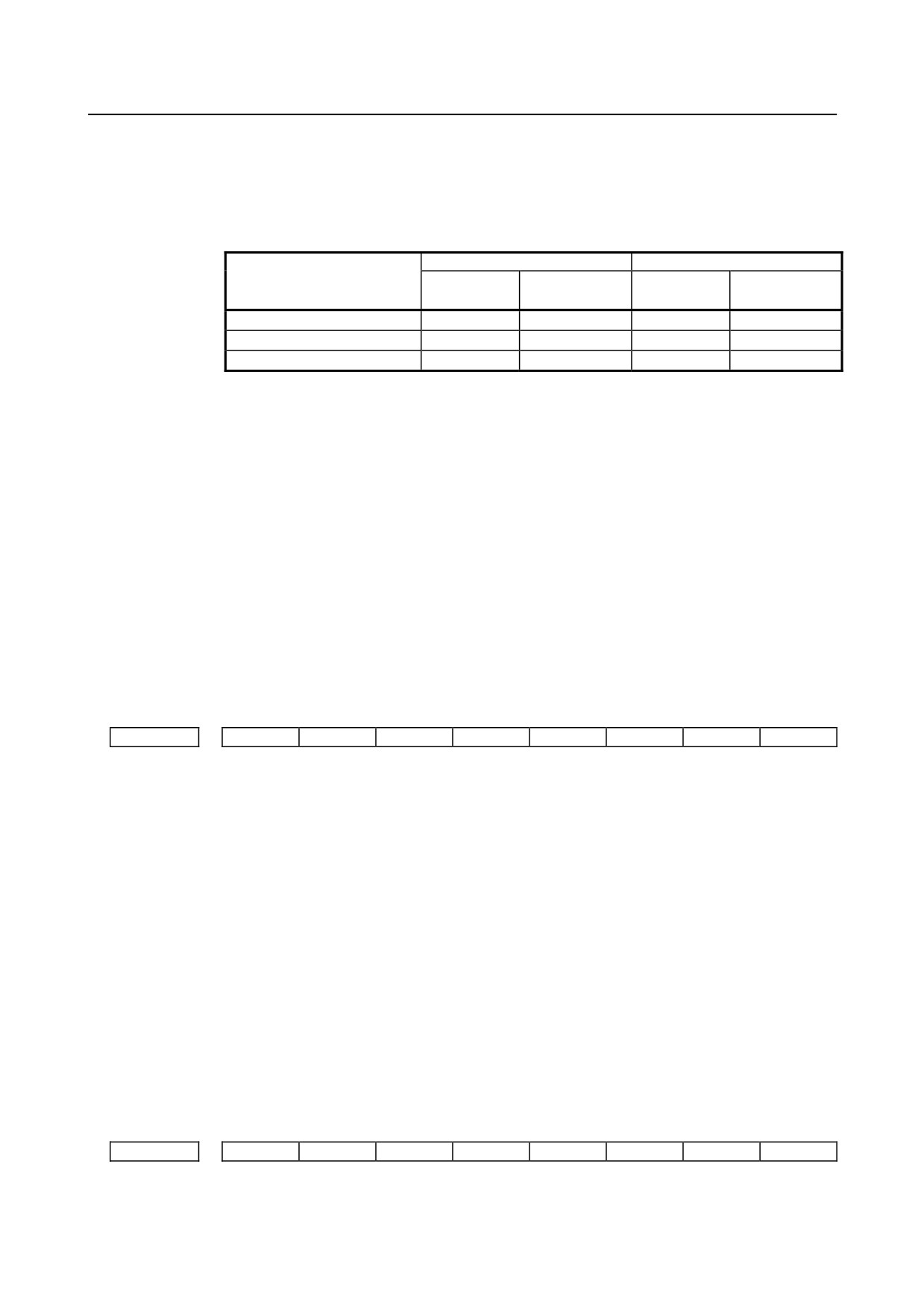
#0 JHD Manual handle feed in JOG feed mode or incremental feed in the manual handle feed
0: Invalid
1: Valid
When JHD:=0
When JHD:=1
JOG feed
Manual handle
JOG feed
Manual handle
mode
feed mode
mode
feed mode
JOG feed
○
×
○
×
Manual handle feed
×
○
○
○
Incremental feed
×
×
×
○
#1 THD In the TEACH IN JOG mode, the manual pulse generator is:
0: Disabled.
1: Enabled.
#3 HCL The clearing of handle interruption amount display by soft key [CAN] operation is:
0: Disabled.
1: Enabled.
#5 MPX In Manual handle feed mode, manual handle feed amount selection signal is
0 : same for all manual pulse generator, and it is set by signals MP1 and
MP2<Gn019.4,.5>.
1 : differ to each other manual pulse generator, and it’s setting signal as follow:
1st. Manual Pulse Generator : MP1,MP2<Gn019.4,.5>
2nd. Manual Pulse Generator : MP21,MP22<Gn087.0,.1>
3rd. Manual Pulse Generator : MP31,MP32<Gn087.3,.4>
#7
#6
#5
#4
#3
#2
#1
#0
7102
HNAx
HNGx
[Input type] Parameter input
[Data type] Bit axis
#0 HNGx Axis movement direction for rotation direction of manual pulse generator
0: Same in direction
1: Reverse in direction
#1 HNAx When manual handle feed direction inversion signal HDN<Gn0347.1> is set to “1”, the
direction of movement is set for each axis with respect to the rotation direction of the
manual pulse generator.
0: The axis movement direction is the same as the direction in which the manual pulse
generator rotates.
1: The axis movement direction is opposite to the direction in which the manual pulse
generator rotates.
When the rotation direction is reversed by manual handle feed direction inversion signal
HDN<Gn0347.1>, the rotation axis direction obtained by the setting of bit 0 (HNGx) of
parameter No. 7102 is reversed.
#7
#6
#5
#4
#3
#2
#1
#0
7103
HIT
HNT
RTH
[Input type] Parameter input
[Data type] Bit path
- 293 -
4.DESCRIPTION OF PARAMETERS
B-64310EN/02
#1 RTH By a reset or emergency stop, the amount of manual handle interruption is:
0: Not canceled.
1: Canceled.
#2 HNT When compared with the travel distance magnification selected by the manual handle
feed travel distance selection signals (incremental feed signals) (MP1, MP2), the travel
distance magnification for incremental feed/manual handle feed is:
0: Same.
1:
10 times greater.
#3 HIT When compared with the travel distance magnification selected by the manual handle
feed travel distance selection signals (incremental feed signals (MP1, MP2), the travel
distance magnification for manual handle interrupt is:
0: Same.
1:
10 times greater.
#7
#6
#5
#4
#3
#2
#1
#0
7105
LBH
HDX
[Input type] Parameter input
[Data type] Bit
NOTE
When at least one of these parameters is set, the power must be
turned off before operation is continued.
#1 HDX Manual handle for I/O Link connection is:
0: Automatically set.
1: Manually set.
NOTE
In manual setting, parameters No.12300 to No.12302 must be set by
manual to connect Manual Pulse Generator with I/O Link.
#5 LBH Manual handle feed for the I/O Link β using the I/O link manual pulse generator is:
0: Disabled.
1: Enabled.
7113
Manual handle feed magnification m
[Input type] Parameter input
[Data type] Word path
[Valid data range] 1 to 2000
This parameter sets the magnification m when manual handle feed movement selection
signals MP1 and MP2 are set to 0 and 1.
7114
Manual handle feed magnification n
[Input type] Parameter input
[Data type] Word path
[Valid data range] 1 to 2000
This parameter sets the magnification when manual handle feed movement selection
signals MP1 and MP2 are set to 1.
- 294 -
B-64310EN/02
4.DESCRIPTION OF PARAMETERS
7117
Allowable number of pulses that can be accumulated during manual handle feed
[Input type] Parameter input
[Data type] 2-word path
[Unit of data] Pulse
[Valid data range] 0 to 999999999
This parameter sets the number of pulses from the manual pulse generator that exceed the
rapid traverse rate and can be accumulated without being discarded if manual handle feed
faster than the rapid traverse rate is specified.
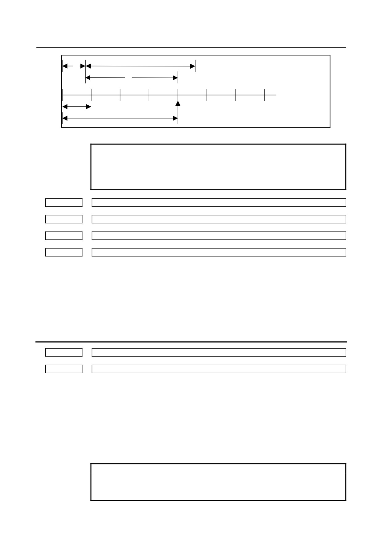
The amount of pulses exceeding the rapid traverse rate can be saved by CNC as B. And
amount of pulses B will be exported as pulses C.
A:amount of pulses corresponds to value of Rapid Traverse Rate.
B:amount of pulses accumulated in CNC.
B
C:amount of pulses the same as B.
Rapid Traverse Rate
A
C
t
Amount of pulses exported by CNC in Manual Handle Feed
Amount of pulses B is calculated in 2 cases as following:
In case of
1)
Parameter No.7117 = 0
The feedrate is clamped at the Rapid Traverse Rate and generated pulses exceeding
the Rapid Traverse Rate are ignored (B=0)
In case of
2)
Parameter No.7117 > 0
The feedrate is clamped as the Rapid Traverse Rate, but the pulses exceeding the
Rapid Traverse Rate is not ignored. Amount of pulses accumulated in CNC is
calculated as following. (Although stopping the rotation of manual pulse generator,
if there is pulses accumulated in CNC, it will be exported and the tool will move as
long as amount of it.)
Magnification set by MP1,MP2<Gn019.4,.5> is m, value of parameter No.7117 is
n.
n < m: Clamping is set performed at value of parameter No.7117.
n ≥ m: Amount A+B, showed in figure, which’s value is multiple of m and small
than n. As a result, clamping is performed as an integral multiple of the selected
magnification.
- 295 -
4.DESCRIPTION OF PARAMETERS
B-64310EN/02
n
A
A: amount of pulses the same as Rapid Traverse Rate.
B: amount of pulses saved in CNC.
B
k : integer number
m
A+B=k⋅m
pulses over (k⋅m) will be ignored
Amount of pulses exceeding the Rapid Traverse Rate (n ≥ m)
NOTE
Due to change of mode, clamping can be performed not as an
integral multiple of the selected magnification.
The distance the tool moves may not match the graduations on the
manual pulse generator.
7131
Manual handle feed magnification m2 / 2nd. manual pulse generator
7132
Manual handle feed magnification n2 / 2nd. manual pulse generator
7133
Manual handle feed magnification m3 / 3rd. manual pulse generator
7134
Manual handle feed magnification n3 / 3rd. manual pulse generator
[Input type] Parameter input
[Data type] Word path
[Valid data range] 1 to 2000
The ‘mx’ is selected when MPx1 = 0, MPx2 = 1.
The ‘nx’ is selected when MPx1 =1, MPx2 = 1.
4.44 PARAMETERS OF REFERENCE POSITION WITH
MECHANICAL STOPPER
7181
First withdrawal distance in reference position setting with mechanical stopper
7182
Second withdrawal distance in butt-type reference position setting with mechanical stopper
[Input type] Parameter input
[Data type] Real axis
[Unit of data] mm, inch, degree (machine unit)
[Min. unit of data] Depend on the increment system of the applied axis
[Valid data range] 9 digit of minimum unit of data (refer to standard parameter setting table (A))
(When the increment system is IS-B, -999999.999 to +999999.999)
This parameter sets a distance an axis in each cycle operation, along which withdrawal is
performed after the mechanical stopper is hit (distance from the mechanical stopper to the
withdrawal point).
NOTE
Set the same direction as that set in bit 5 (ZMIx) of parameter No.
1006. Cycle operation cannot be started if the opposite direction is
set.
- 296 -
B-64310EN/02
4.DESCRIPTION OF PARAMETERS
7183
First butting feedrate in reference position setting with mechanical stopper
7184
Second butting feedrate in reference position setting with mechanical stopper
Withdrawal feedrate (common to the first and second butting operations) in reference position setting
7185
with mechanical stopper
[Input type] Parameter input
[Data type] Real axis
[Unit of data] mm/min, inch/min, degree/min (machine unit)
[Min. unit of data] Depend on the increment system of the applied axis
[Valid data range] Refer to the standard parameter setting table (C)
(When the increment system is IS-B, 0.0 to +999000.0)
This parameter sets a feedrate used to butt against the stopper along an axis in each cycle.
This parameter also sets a feedrate at which an axis is retracted when the axis makes
contact with the machine stopper in each cycle.
7186
Torque limit value in butt-type reference position setting with mechanical stopper
[Input type] Parameter input
[Data type] Byte axis
[Valid data range] 0 to 100
This parameter sets a torque limit value. A value from 0 to 100 corresponds to 0% to 39%.
The torque limit value is obtained by multiplying the setting by 1/255. If more than 39%
is to be set, use parameter No. 7187.
NOTE
When 0 is set in this parameter, 100% is assumed.
7187
Torque limit value in butt-type reference position setting with mechanical stopper
[Input type] Parameter input
[Data type] Word axis
[Valid data range] 0 to 255
This parameter sets a torque limit value. A value from 0 to 255 corresponds to 0% to
100%.
When this parameter is set in butt-type reference position setting, parameter No. 7186 is
ignored.
NOTE
1 When 0 is set in this parameter, 100% is assumed
2 A converted setting must not exceed the rated torque.
4.45 PARAMETERS OF SOFTWARE OPERATOR'S PANEL
#7
#6
#5
#4
#3
#2
#1
#0
7200
OP7
OP6
OP5
OP4
OP3
OP2
OP1
[Input type] Parameter input
[Data type] Bit path
- 297 -
4.DESCRIPTION OF PARAMETERS
B-64310EN/02
NOTE
When at least one of these parameters is set, the power must be
turned off before operation is continued.
#0
OP1 Mode selection on software operator's panel
0: Not performed
1: Performed
#1
OP2 JOG feed axis select and manual rapid traverse select on software operator's panel
0: Not performed
1: Performed
#2
OP3 Manual pulse generator's axis select and manual pulse generator's magnification select on
software operator's panel
0: Not performed
1: Performed
#3
OP4 JOG feedrate override select, feedrate override select, and rapid traverse override select
on software operator's panel
0: Not performed
1: Performed
#4
OP5 Optional block skip select, single block select, machine lock select, and dry run select on
software operator's panel
0: Not performed
1: Performed
#5
OP6 Protect key on software operator's panel
0: Not performed
1: Performed
#6
OP7 Feed hold on software operator's panel
0: Not performed
1: Performed
#7
#6
#5
#4
#3
#2
#1
#0
7201
GPS
[Input type] Parameter input
[Data type] Bit path
#1 GPS The maximum number of switches of the general-purpose switch function on the software
operator's panel is:
0:
8.
1:
16.
7210
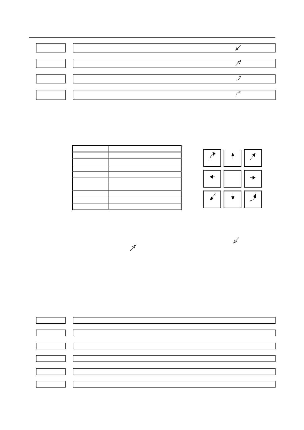
Jog-movement axis and its direction on software operator's panel “↑”
7211
Jog-movement axis and its direction on software operator's panel “↓”
7212
Jog-movement axis and its direction on software operator's panel “→”
7213
Jog-movement axis and its direction on software operator's panel “←”
- 298 -
B-64310EN/02
4.DESCRIPTION OF PARAMETERS
7214
Jog-movement axis and its direction on software operator's panel “
”
7215
Jog-movement axis and its direction on software operator's panel “
”
7216
Jog-movement axis and its direction on software operator's panel “
”
7217
Jog-movement axis and its direction on software operator's panel “
”
[Input type] Parameter input
[Data type] Byte path
[Valid data range] 0 to 8
On software operator's panel, set a feed axis corresponding to an arrow key on the MDI
panel when jog feed is performed.
Arrow keys on MDI panel
Setting value
Feed axis and direction
0
Not moved
1
First axis, positive direction
7
8
9
2
First axis, negative direction
3
Second axis, positive direction
4
Second axis, negative direction
4
5
6
5
Third axis, positive direction
6
Third axis, negative direction
7
Fourth axis, positive direction
1
2
3
8
Fourth axis, negative direction
[Example] Under X, Y, and Z axis configuration, to set arrow keys to feed the axes in the direction
specified as follows, set the parameters to the values given below. [8↑] to the positive
direction of the Z axis, [2↓] to the negative direction of the Z axis, [6→] to the positive
direction of the X axis [4←] to the negative direction of the X axis, [1
] to the positive
direction of the Y axis, [9
] to the negative direction of the Y axis
Parameter No.7210 = 5 (Z axis, positive direction)
Parameter No.7211 = 6 (Z axis, negative direction)
Parameter No.7212 = 1 (X axis, positive direction)
Parameter No.7213 = 2 (X axis, negative direction)
Parameter No.7214 = 3 (Y axis, positive direction)
Parameter No.7215 = 4 (Y axis, negative direction)
Parameter No.7216 = 0 (Not used)
Parameter No.7217 = 0 (Not used)
7220
Name of general-purpose switch 1 on software operator's panel (first character)
to
to
7283
Name of general-purpose switch 8 on software operator's panel (eighth character)
7284
Name of general-purpose switch 9 on software operator's panel (first character)
to
to
7299
Name of general-purpose switch 10 on software operator's panel (eighth character)
7352
Name of general-purpose switch 11 on software operator's panel (first character)
to
to
7399
Name of general-purpose switch 16 on software operator's panel (eighth character)
[Input type] Parameter input
- 299 -
4.DESCRIPTION OF PARAMETERS
B-64310EN/02
[Data type] Byte path
[Valid data range] -128 to 127
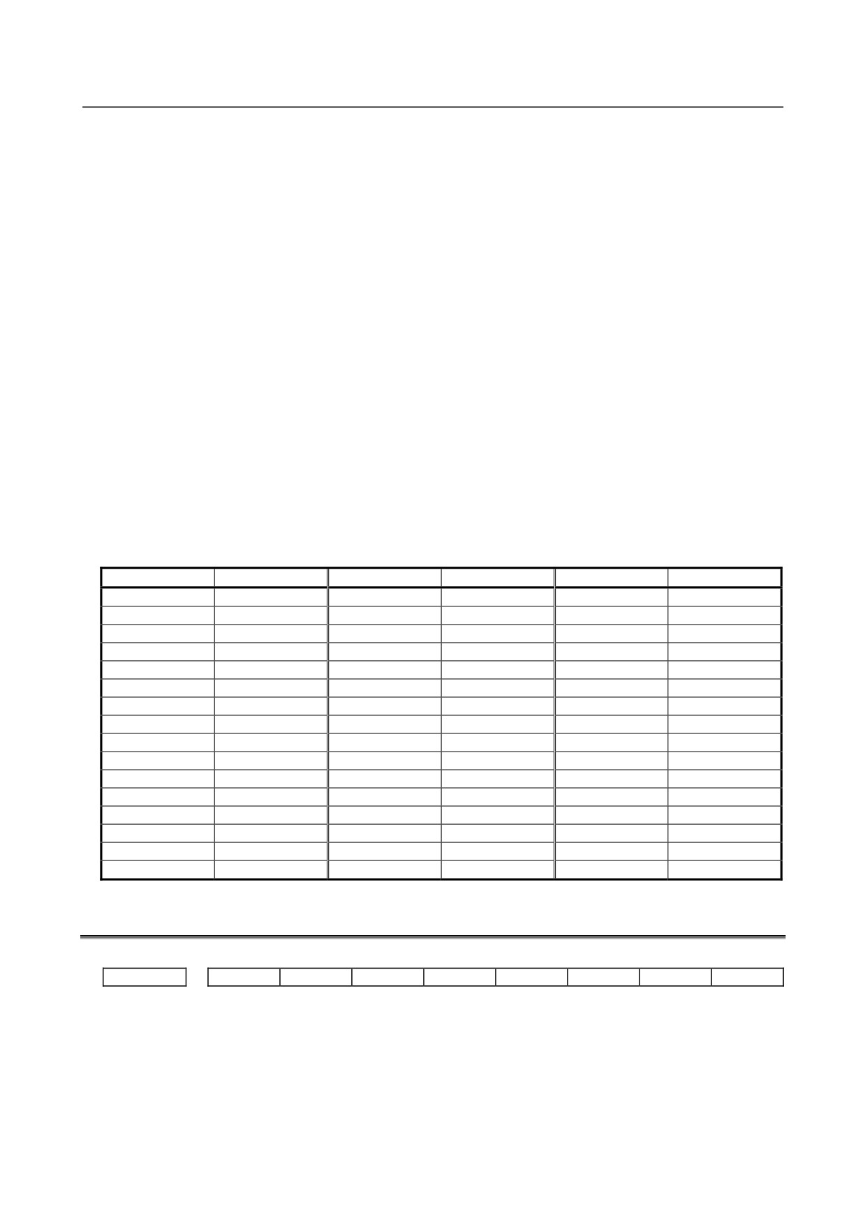
Each of these parameters sets the name of a general-purpose switch on the software
operator's panel with character codes indicated in the character-code correspondence table.
A switch name consists of up to eight characters.
Parameter Nos. 7220 to 7227 : Name of general-purpose switch 1
Parameter Nos. 7228 to 7235 : Name of general-purpose switch 2
Parameter Nos. 7236 to 7243 : Name of general-purpose switch 3
Parameter Nos. 7244 to 7251 : Name of general-purpose switch 4
Parameter Nos. 7252 to 7259 : Name of general-purpose switch 5
Parameter Nos. 7260 to 7267 : Name of general-purpose switch 6
Parameter Nos. 7268 to 7275 : Name of general-purpose switch 7
Parameter Nos. 7276 to 7283 : Name of general-purpose switch 8
Parameter Nos. 7284 to 7291 : Name of general-purpose switch 9
Parameter Nos. 7292 to 7299 : Name of general-purpose switch 10
Parameter Nos. 7352 to 7359 : Name of general-purpose switch 11
Parameter Nos. 7360 to 7367 : Name of general-purpose switch 12
Parameter Nos. 7368 to 7375 : Name of general-purpose switch 13
Parameter Nos. 7376 to 7383 : Name of general-purpose switch 14
Parameter Nos. 7384 to 7391 : Name of general-purpose switch 15
Parameter Nos. 7392 to 7399 : Name of general-purpose switch 16
Character code list
Character
Code
Character
Code
Character
Code
A
65
Q
81
6
54
B
66
R
82
7
55
C
67
S
83
8
56
D
68
T
84
9
57
E
69
U
85
32
F
70
V
86
!
33
G
71
W
87
“
34
H
72
X
88
#
35
I
73
Y
89
$
36
J
74
Z
90
%
37
K
75
0
48
&
38
L
76
1
49
‘
39
M
77
2
50
(
40
N
78
3
51
)
41
O
79
4
52
42
P
80
5
53
+
43
4.46 PARAMETERS OF PROGRAM RESTART
#7
#6
#5
#4
#3
#2
#1
#0
7300
MOU
MOA
[Input type] Parameter input
[Data type] Bit path
#6 MOA In program restart operation, before movement to a machining restart point:
0: The last M, S, T, and B codes are output.
1: All M codes and the last S, T, and B codes are output.
This parameter is enabled when the MOU parameter is set to 1.
- 300 -
B-64310EN/02
4.DESCRIPTION OF PARAMETERS
#7 MOU In program restart operation, before movement to a machining restart point after restart
block search:
0: The M, S, T, and B codes are not output.
1: The last M, S, T, and B codes are output.
#7
#6
#5
#4
#3
#2
#1
#0
7301
ROF
[Input type] Parameter input
[Data type] Bit path
#0 ROF When the coordinates for restarting are displayed on the program restart screen:
0: Tool length compensation (M series), tool position compensation (T series), cutter
compensation
(M series), and tool-nose radius compensation
(T series) are
considered.
1: Whether these compensation values are considered depends on the settings of bit 6
(DAL) of parameter No.3104, bit 7 (DAC) of parameter No.3104, and bit 1 (DAP)
of parameter No.3129
(parameters for specifying whether to consider each
compensation value).
7310
Ordinal number of an axis along which a movement is made in dry run after program restart
[Input type] Setting input
[Data type] Byte axis
[Valid data range] 1 to Number of controlled axes
This parameter sets the ordinal number of an axis along which a movement is made in dry
run after the program is restarted.
4.47 PARAMETERS OF POLYGON TURNING (T SERIES)
#7
#6
#5
#4
#3
#2
#1
#0
PLZ
7600
[Input type] Parameter input
[Data type] Bit path
#7 PLZ Reference position return based on a G28 command on the tool rotation axis for polygon
turning is:
0: Performed in the same sequence as manual reference position return.
1: Performed by positioning using the rapid traverse rate.
The synchronous axis returns to the reference position in the same sequence as the
manual reference position return when no return-to-reference position is performed after
the power is turned on.
#7
#6
#5
#4
#3
#2
#1
#0
COF
HST
HSL
HDR
SNG
MNG
7602
[Input type] Parameter input
[Data type] Bit path
- 301 -

4.DESCRIPTION OF PARAMETERS
B-64310EN/02
#0 MNG The rotational direction of the master axis in the spindle-spindle polygon turning mode is:
0: Not reversed.
1: Reversed.
#1 SNG The rotational direction of the polygon synchronization axis in the spindle-spindle
polygon turning mode is:
0: Not reversed.
1: Reversed.
#2 HDR When phase control is exercised in spindle-spindle polygon turning mode (parameter
COF(No.7602#5) is set to 0), the phase shift direction is:
0: Not reversed for phase synchronization.
1: Reversed for phase synchronization.
NOTE
The rotation directions and phase shift directions of the master axis
and polygon synchronization axis in the spindle-spindle polygon
turning mode can be reversed with a programmed command. MNG,
SNG, and HDR are used to reverse an actual direction relative to the
programmed command.
#3
HSL When phase control is exercised in spindle-spindle polygon turning mode (parameter
COF(No.7602#5) is set to 0), this parameter selects the spindle that is subject to a phase
shift operation for phase synchronization:
0: The polygon synchronization axis is selected.
1: The master axis is selected.
NOTE
1 Select an axis to which a phase shift command is applied.
2 Spindle operation for phase synchronization is performed with both
spindles.
#4
HST When phase control is applied in spindle-spindle polygon turning mode (parameter
COF(No.7602#5) is set to 0), and spindle-spindle polygon turning mode is specified:
0: Spindle-spindle polygon turning mode is entered with the current spindle speed
maintained.
1: Spindle-spindle polygon turning mode is entered after the spindle is stopped.
NOTE
This parameter can be used, for example, when single-rotation
signal detection cannot be guaranteed at an arbitrary feedrate
because a separate detector is installed to detect the spindle
single-rotation signal, as when a built-in spindle is used. (When bit
7 (RFCHK3) of parameter No.4016 for the serial spindle is set to 1,
together with this parameter, a single-rotation signal detection
position in spindle-spindle polygon turning mode is guaranteed.)
#5 COF In spindle-spindle polygon turning mode, phase control is:
0: Enabled.
1: Disabled.
- 302 -
B-64310EN/02
4.DESCRIPTION OF PARAMETERS
NOTE
When the use of phase control is not selected, the steady state is
reached in a shorter time because phase synchronization control is
not applied. Once steady rotation is achieved, however, polygon
turning must be completed without changing the steady state. (If a
spindle speed change including a spindle stop is made, a phase
shift occurs, so that polygon turning is not performed normally.)
Even when this parameter is set to 1, an R command (phase
position command) in a block containing G51.2 is ignored ; no
alarm is issued.
#7
#6
#5
#4
#3
#2
#1
#0
PST
RDG
PLR
SBR
QDR
RPL
7603
[Input type] Parameter input
[Data type] Bit path
#0 RPL Upon reset, spindle-spindle polygon turning mode is:
0: Released.
1: Not released.
#1 QDR The rotational direction of the polygon synchronization axis:
0: Depends on the sign (+/-) of a specified value for Q.
1: Depends on the rotational direction of the first spindle.
If a negative value is specified for Q when QDR = 1, the alarm (PS0218) is issued.
#2 SBR For spindle synchronization, speed ratio control is:
0: Not used.
1: Used.
NOTE
1 This parameter sets the speed of the slave spindle to an integral
multiple of the speed of the master spindle in the spindle
synchronization control function.
2 There is no relation with the polygon machining function.
3 Spindle synchronization control needs to be enabled.
4 Parameters No.7635 and No.7636 need to be set.
#3 PLR The machine coordinates of a tool rotation axis for polygon turning are:
0: Rounded by the setting in parameter No.7620.
1: Rounded by 360° (or the setting in parameter No. 1260 when bit 0 (ROA) of
parameter No. 1008 is set to 1).
#5 RDG On the diagnosis screen No.476, for spindle-spindle polygon phase command value (R),
displays:
0: The specified value (in the increment system for the rotation axis).
1: The actual number of shift pulses.
- 303 -
4.DESCRIPTION OF PARAMETERS
B-64310EN/02
NOTE
A phase command is specified in address R, in units of degrees.
For control, the actual shift amount is converted to a number of
pulses according to the conversion formula: 360 degrees = 4096
pulses. This parameter switches the display of a specified value to
that of a converted value.
#7 PST The polygon spindle stop signal *PLSST <Gn038.0>is:
0: Not used.
1: Used.
Control axis number of tool rotation axis for polygon turning
7610
NOTE
When this parameter is set, the power must be turned off before
operation is continued.
[Input type] Parameter input
[Data type] Byte path
[Valid data range] 1 to number of controlled axes
This parameter sets the control axis number of a rotation tool axis used for polygon
turning.
However, when a G51.2 command is executed by setting 0 in this parameter, operation
stops with the alarm (PS0314).
Movement of tool rotation axis per revolution for polygon turning
7620
NOTE
When this parameter is set, the power must be turned off before
operation is continued.
[Input type] Parameter input
[Data type] Real path
[Unit of data] Degree
[Min. unit of data] Depend on the increment system of the applied axis
[Valid data range] 0 or positive 9 digit of minimum unit of data (refer to the standard parameter setting table
(B))
(When the increment system is IS-B, 0.0 to +999999.999)
This parameter sets the movement of a tool rotation axis per revolution.
Maximum allowable speed for the tool rotation axis for polygon turning
7621
[Input type] Parameter input
[Data type] 2-word path
[Unit of data] min-1
[Valid data range] 0 or positive 9 digit of minimum unit of data (refer to the standard parameter setting table
(B))
(When the increment system is IS-B, 0.0 to +999999.999)
This parameter sets the maximum allowable speed of the tool rotation axis.
- 304 -
B-64310EN/02
4.DESCRIPTION OF PARAMETERS
NOTE
If the speed of a tool rotation axis (polygon synchronization axis)
exceeds the set upper limit during polygon machining, clamping is
performed at the upper limit. When clamping is performed at the
upper limit, the synchronization between the spindle and the tool
rotation axis (polygon synchronization axis) deviates. If clamping
is performed, an alarm (PS5018) occurs.
Allowable spindle speed deviation level in spindle-spindle polygon turning
7631
[Input type] Parameter input
[Data type] Word path
[Unit of data] min-1
[Valid data range] 0 to 99999999
This parameter sets the allowable level of deviation between the actual speed and
specified speed of each spindle in spindle-spindle polygon turning. The value set with this
parameter is used for both the master axis and polygon synchronization axis.
When 0 is set in this parameter, the specification of 8 [min-1] is assumed.
Steady state confirmation time duration in spindle polygon turning
7632
[Input type] Parameter input
[Data type] Word path
[Unit of data] msec
[Valid data range] 0 to 32767
This parameter sets the duration required to confirm that both spindles have reached their
specified speeds in spindle-spindle polygon turning.
If the state where the speed of each spindle is within the range set with parameter
No.7631, and has lasted at least for the duration specified with parameter No.7632, the
spindle polygon speed arrival signal PSAR <Fn063.2> is set to 1.
When 0 is set in this parameter, the specification of 64 [msec] is assumed.
Ratio of slave spindle speed in spindle synchronization control
7635
[Input type] Parameter input
[Data type] Byte spindle
[Valid data range] 0 to 9
This parameter sets the ratio of master spindle speed:slave spindle speed (1:n) in spindle
synchronization control.
NOTE
1 This parameter sets the speed of the slave spindle to an integral
multiple of the speed of the master spindle in the spindle
synchronization control function.
2 There is no relation with the polygon machining function.
3 Spindle synchronization control needs to be enabled.
4 Bit 2 of parameters No.7603 and parameter No.7636 need to be
set.
- 305 -
4.DESCRIPTION OF PARAMETERS
B-64310EN/02
Maximum allowable slave spindle speed in spindle synchronization control
7636
[Input type] Parameter input
[Data type] Word spindle
[Unit of data] min-1
[Valid data range] 0 to 19999
The speed of the slave spindle under speed ratio control in spindle synchronization
control is clamped so that the speed does not exceed the value set in this parameter.
NOTE
1 This parameter sets the speed of the slave spindle to an integral
multiple of the speed of the master spindle in the spindle
synchronization control function.
2 There is no relation with the polygon machining function.
3 Spindle synchronization control needs to be enabled.
4 Bit 2 of parameters No.7603 and parameter No.7635 need to be
set.
5 When speed ratio control in spindle synchronization control is used,
be sure to set this parameter. When 0 is set, the speed is clamped
to 0, disabling rotation under spindle synchronization.
Master axis in spindle-spindle polygon turning
7640
[Input type] Parameter input
[Data type] Byte path
[Valid data range] 0 to Maximum number of controlled axes (Within a path)
This parameter sets the master axis in spindle-spindle polygon turning.
NOTE
1 Spindle-spindle polygon turning is enabled only for serial spindles.
2 When any one of parameter No. 7640 and No. 7641 is set to 0,
polygon turning is performed using the first spindle (master axis)
and the second spindle (polygon synchronous axis) in the path to
which the parameter belongs.
3 When an axis other than the first serial spindle is selected as the
master axis, multi-spindle control is required to execute an S
command for the master axis.
4 When the PMC window function or G10 command is used to
rewrite this parameter, rewrite this parameter before the block
specifying the spindle-spindle polygon command G51.2. When the
PMC window function is used to rewrite this parameter in the block
immediately before G51.2, specify the rewriting of this parameter
by using an M code (parameter No. 3411 and up) without buffering.
Polygon synchronous axis in spindle-spindle polygon turning
7641
[Input type] Parameter input
[Data type] Byte path
[Valid data range] 0 to Maximum number of controlled axes (Within a path)
- 306 -

B-64310EN/02
4.DESCRIPTION OF PARAMETERS
This parameter sets the polygon synchronous (slave) axis in spindle-spindle polygon
turning.
NOTE
1 Spindle-spindle polygon turning is enabled only for serial spindles.
2 When any one of parameter No. 7640 and No. 7641 is set to 0,
polygon turning is performed using the first spindle (master axis)
and the second spindle (polygon synchronous axis) in the path to
which the parameter belongs.
3 When an axis other than the first serial spindle is selected as the
master axis, multi-spindle control is required to execute an S
command for the master axis.
4 When the PMC window function or G10 command is used to
rewrite this parameter, rewrite this parameter before the block
specifying the spindle-spindle polygon command G51.2. When the
PMC window function is used to rewrite this parameter in the block
immediately before G51.2, specify the rewriting of this parameter
by using an M code (parameter No. 3411 and up) without buffering.
Master axis in spindle-spindle polygon turning (spindle number common to the system)
7642
[Input type] Parameter input
[Data type] Byte path
[Valid data range] 0 to Maximum number of controlled axes (Common to the system)
This parameter sets the master axis in spindle-spindle polygon turning.
NOTE
1 Spindle-spindle polygon turning is enabled only for serial spindles.
2 This parameter is invalid if either parameter No. 7642 or No.7643 is
set to 0. In this case, the settings of parameter No. 7640 and
No.7641 are valid.
3 When an axis other than the first serial spindle is selected as the
master axis, multi-spindle control is required to execute an S
command for the master axis.
4 When the PMC window function or G10 command is used to
rewrite this parameter, rewrite this parameter before the block
specifying the spindle-spindle polygon command G51.2. When the
PMC window function is used to rewrite this parameter in the block
immediately before G51.2, specify the rewriting of this parameter
by using an M code (parameter No. 3411 and up) without buffering.
5 A spindle number common to the system is to be set in this
parameter. When using this parameter, set 0 in parameter No.
7640 and No. 7641.
Polygon synchronous axis in spindle-spindle polygon turning (spindle number common to the system)
7643
[Input type] Parameter input
[Data type] Byte path
[Valid data range] 0 to Maximum number of controlled axes (Common to the system)
- 307 -
4.DESCRIPTION OF PARAMETERS
B-64310EN/02
This parameter sets the polygon synchronous (slave) axis in spindle-spindle polygon
turning.
NOTE
1 Spindle-spindle polygon turning is enabled only for serial spindles.
2 This parameter is invalid if either parameter No. 7642 or No.7643 is
set to 0. In this case, the settings of parameter No. 7640 and
No.7641 are valid.
3 When an axis other than the first serial spindle is selected as the
master axis, multi-spindle control is required to execute an S
command for the master axis.
4 When the PMC window function or G10 command is used to
rewrite this parameter, rewrite this parameter before the block
specifying the spindle-spindle polygon command G51.2. When the
PMC window function is used to rewrite this parameter in the block
immediately before G51.2, specify the rewriting of this parameter
by using an M code (parameter No. 3411 and up) without buffering.
5 A spindle number common to the system is to be set in this
parameter. When using this parameter, set 0 in parameter No.
7640 and No. 7641.
4.48
PARAMETERS OF THE ELECTRONIC GEAR BOX (EGB)
(M SERIES) / GENERAL-PURPOSE RETRACTION
#7
#6
#5
#4
#3
#2
#1
#0
7700
HDR
HBR
[Input type] Parameter input
[Data type] Bit path
#0 HBR When the electronic gear box (EGB) function is used, performing a reset:
0: Cancels the synchronous mode (G81).
1: Does not cancel the synchronous mode. The mode is canceled only by the G80
command.
#2 HDR Direction of helical gear compensation (usually, set 1.)
(Example) To cut a left-twisted helical gear when the direction of rotation about the
C-axis is the negative (-) direction:
0: Set a negative (-) value in P.
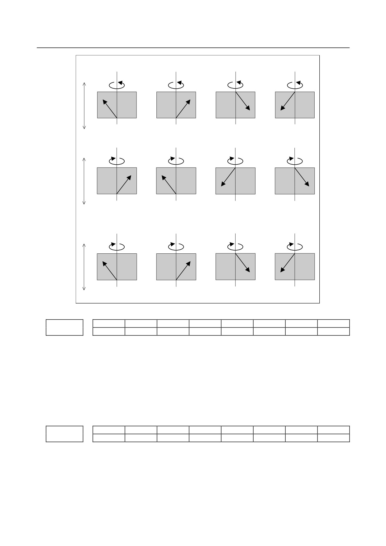
1: Set a positive (+) value in P.
- 308 -
B-64310EN/02
4.DESCRIPTION OF PARAMETERS
When HDR = 1
(a)
(b)
(c)
(d)
+Z
+C
+C
+C
+C
C : +, Z : +, P : +
C : +, Z : +, P : -
C : +, Z : -, P : +
C : +, Z : -, P : -
Compensation direction:+
Compensation direction:-
Compensation direction:-
Compensation direction:+
-Z
(e)
(f)
(g)
(h)
+Z
-C
-C
-C
-C
C : -, Z : +, P : +
C : -, Z : +, P : -
C : -, Z : -, P : +
C : -, Z : -, P : -
Compensation direction:+
Compensation direction:-
-Z C : Compensation direction:-Compensation direction:+
When HDR = 0 ((a), (b), (c), and (d) are the same as when HDR = 1)
(e)
(f)
(g)
(h)
+Z
-C
-C
-C
-C
C : -, Z : +, P : +
C : -, Z : +, P : -
C : -, Z : -, P : +
C : -, Z : -, P : -
Compensation direction:-
Compensation direction:-
Compensation direction:+
-Z Compensation direction:+
#7
#6
#5
#4
#3
#2
#1
#0
7701
LZR
[Input type] Parameter input
[Data type] Bit path
#3 LZR When L (number of hob threads) = 0 is specified at the start of EGB synchronization
(G81):
0: Synchronization is started, assuming that L = 1 is specified.
1: Synchronization is not started, assuming that L = 0 is specified. However, helical
gear compensation is performed.
#7
#6
#5
#4
#3
#2
#1
#0
7702
ART
TDP
[Input type] Parameter input
[Data type] Bit path
#0 TDP The specifiable number of teeth, T, of the electronic gear box (G81) is:
0:
1 to 1000
1:
0.1 to 100 (1/10 of a specified value)
- 309 -
4.DESCRIPTION OF PARAMETERS
B-64310EN/02
NOTE
In either case, a value from 1 to 1000 can be specified.
#3 ART The retract function executed when an alarm is issued is:
0: Disabled.
1: Enabled.
When an alarm is issued, a retract operation is performed with a set feedrate and travel
distance (parameter Nos. 7740 and 7741).
NOTE
If a servo alarm is issued for other than the axis along which a
retract operation is performed, the servo activating current is
maintained until the retract operation is completed.
#7
#6
#5
#4
#3
#2
#1
#0
7703
ARO
ARE
ERV
[Input type] Parameter input
[Data type] Bit path
#0 ERV During EGB synchronization (G81), feed per revolution is performed for:
0: Feedback pulses.
1: Pulses converted to the speed for the workpiece axis.
#1 ARE In the retract function by an alarm, retract operation is:
0: Performed during EGB synchronization or automatic operation (automatic operation
signal = 1).
1: Determined by the setting of parameter ARO.
#2
ARO The retract function executed when an alarm is issued retracts the tool during:
0: EGB synchronization.
1: EGB synchronization and automatic operation (automatic operation signal OP = 1).
NOTE
This parameter is valid when bit 1 (ARE) of parameter No. 7703 is
set to 1.
The following table lists the parameter settings and corresponding operation.
ARE
ARO
Operation
1
0
During EGB synchronization
1
1
During EGB synchronization and automatic operation
0
0
During EGB synchronization or automatic operation
0
1
NOTE
Parameters ARE and ARO are valid when bit 3 (ART) of parameter
No. 7702 is set to 1 (when the retract function executed when an
alarm is issued ).
- 310 -
B-64310EN/02
4.DESCRIPTION OF PARAMETERS
#7
#6
#5
#4
#3
#2
#1
#0
7704
ACR
[Input type] Parameter input
[Data type] Bit path
#0 ACR In the advanced preview control, AI advanced preview control, or AI contour control
mode, general purpose retract operation is:
0: Not Used.
1: Used.
7709
Number of the axial feed axis for helical compensation
[Input type] Parameter input
[Data type] 2-word path
[Valid data range] 0 to Number of controlled axes
This parameter sets the number of the axial feed axis for a helical gear.
NOTE
When this parameter is set to 0 or a value outside the set range,
the Z-axis is selected as the axial feed axis.
#7
#6
#5
#4
#3
#2
#1
#0
7731
RTS
ECN
EHF
EFX
[Input type] Parameter input
[Data type] Bit path
#0 EFX As the EGB command:
0: G80 and G81 are used.
1: G80.4 and G81.4 are used.
NOTE
When this parameter is set to 0, no drilling canned cycle can be
used.
#1 EHF Feed-forward control for the axial feed axis for helical compensation is:
0: Enabled only during cutting.
1: Always enabled in the G81 synchronous mode.
Usually, set 0.
Feed-forward control is usually enabled in the cutting feed mode. When this parameter
is set to 1, feed-forward control is always enabled for the axial feed axis for helical
compensation during synchronization by the command (G81) for a hobbing machine.
When bit 3 (FFR) of parameter No. 1800 is set to 1, feed-forward control is always
enabled regardless of the setting of this parameter.
#3 ECN During EGB synchronization:
0: G81 cannot be specified again.
(An alarm (PS1595) occurs.)
1: G81 can be specified.
- 311 -
4.DESCRIPTION OF PARAMETERS
B-64310EN/02
#4 RTS When an OT alarm or axis type malfunction protection alarm is issued during EGB
retract operation:
0: Only the axis for which the alarm is issued is stopped.
1: All axes are stopped.
7740
Feedrate during retraction
[Input type] Parameter input
[Data type] Real axis
[Unit of data] mm/min, inch/min, degree/min (machine unit)
[Min. unit of data] Depend on the increment system of the applied axis
[Valid data range] Refer to the standard parameter setting table (C)
(When the increment system is IS-B, 0.0 to +999000.0)
This parameter sets the feedrate during retraction for each axis.
7741
Retracted distance
[Input type] Parameter input
[Data type] Real axis
[Unit of data] mm, inch, degree (machine unit)
[Min. unit of data] Depend on the increment system of the applied axis
[Valid data range] 9 digit of minimum unit of data (refer to standard parameter setting table (A))
(When the increment system is IS-B, -999999.999 to +999999.999)
This parameter sets the retracted distance for each axis.
7745
Time constant for linear acceleration/deceleration in retract operation for each axis
[Input type] Parameter input
[Data type] word axis
[Unit of data] msec
[Valid data range] 0 to 1000
This parameter sets an acceleration rate for linear acceleration/deceleration in retract operation based on the
general-purpose retract function. Set a time (Time constant) used to reach the federate set
in parameter No.7740 for each axis.
NOTE
This parameter is valid when bit 0 (ACR) of parameter No. 7704 is
set to 1 to perform a retract operation in the advanced preview
control, AI advanced preview control, or AI contour control mode.
7772
Number of position detector pulses per rotation about the tool axis
[Input type] Parameter input
[Data type] 2-word path
[Valid data range] 1 to 999999999
This parameter sets the number of pulses per rotation about the tool axis (on the spindle
side), for the position detector.
For an A/B phase detector, set this parameter with four pulses equaling one A/B phase
cycle.
- 312 -
B-64310EN/02
4.DESCRIPTION OF PARAMETERS
NOTE
Specify the number of feedback pulses per rotation about the tool
axis for the position detector, considering the gear ratio with
respect to the position coder.
7773
Number of position detector pulses per rotation about the workpiece axis
[Input type] Parameter input
[Data type] 2-word path
[Valid data range] 1 to 999999999
This parameter sets the number of pulses per rotation about the workpiece axis (on the
slave side), for the position detector.
Set the number of pulses output by the detection unit.
Set parameters Nos. 7772 and 7773 when using the G81 EGB synchronization command.
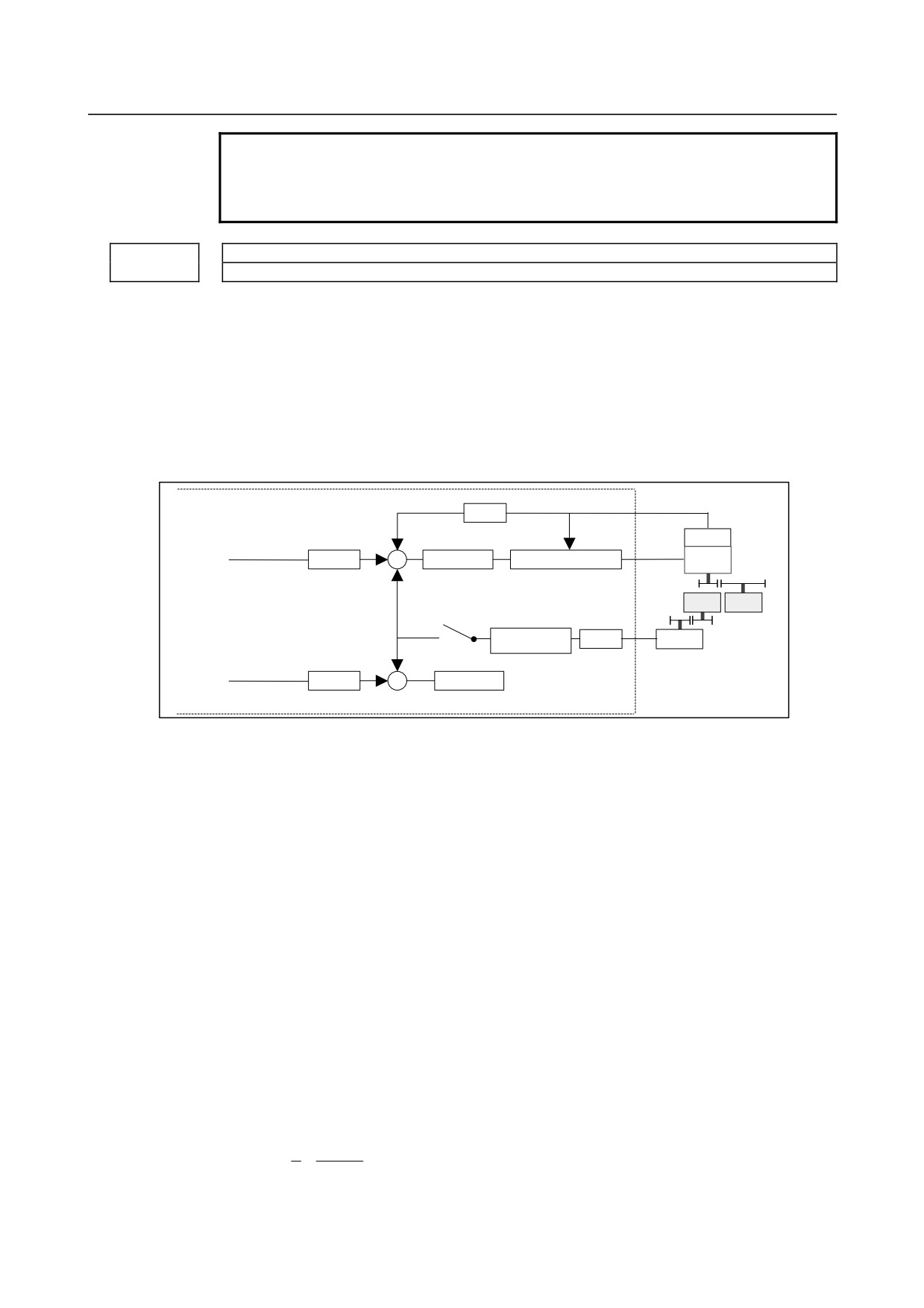
[Example 1] When the EGB master axis is the spindle and the EGB slave axis is the C-axis
CNC
×FFG
α p/rev
n/m
Command
Detector
pulses
×CMR
Error counter
Speed/current control
Motor
Slave axis
Gear ratio
Least command increment
A
0.001deg
Detection unit
Gear
Spindle
C-axis
ratio B
Synchronization
Detector
×FFG
Synchronization
factor
N/M
β p/rev
switch
Follow-up
Dummy axis
×CMR
Error counter
Gear ratio of the spindle to the detector B:
1/1 (The spindle and detector are directly connected to each other.)
Number of detector pulses per spindle rotation β: 80,000 pulses/rev
(Calculated for four pulses for one A/B phase cycle)
FFG N/M of the EGB dummy axis:
1/1
Gear ratio of the C-axis A:
1/36 (One rotation about the C-axis to 36 motor rotations)
Number of detector pulses per C-axis rotation α: 1,000,000 pulses/rev
C-axis CMR:
1
C-axis FFG n/m:
1/100
In this case, the number of pulses per spindle rotation is:
80000 × 1/1 = 80000
Therefore, set 80000 for parameter No. 7772.
The number of pulses per C-axis rotation in the detection unit is:
1000000 ÷ 1/36 × 1/100 = 360000
Therefore, set 360000 for parameter No. 7773.
[Example 2] When the gear ratio of the spindle to the detector B is 2/3 for the above example (When
the detector rotates twice for three spindle rotations)
In this case, the number of pulses per spindle rotation is:
2
160000
80000 ×
=
3
3
- 313 -
4.DESCRIPTION OF PARAMETERS
B-64310EN/02
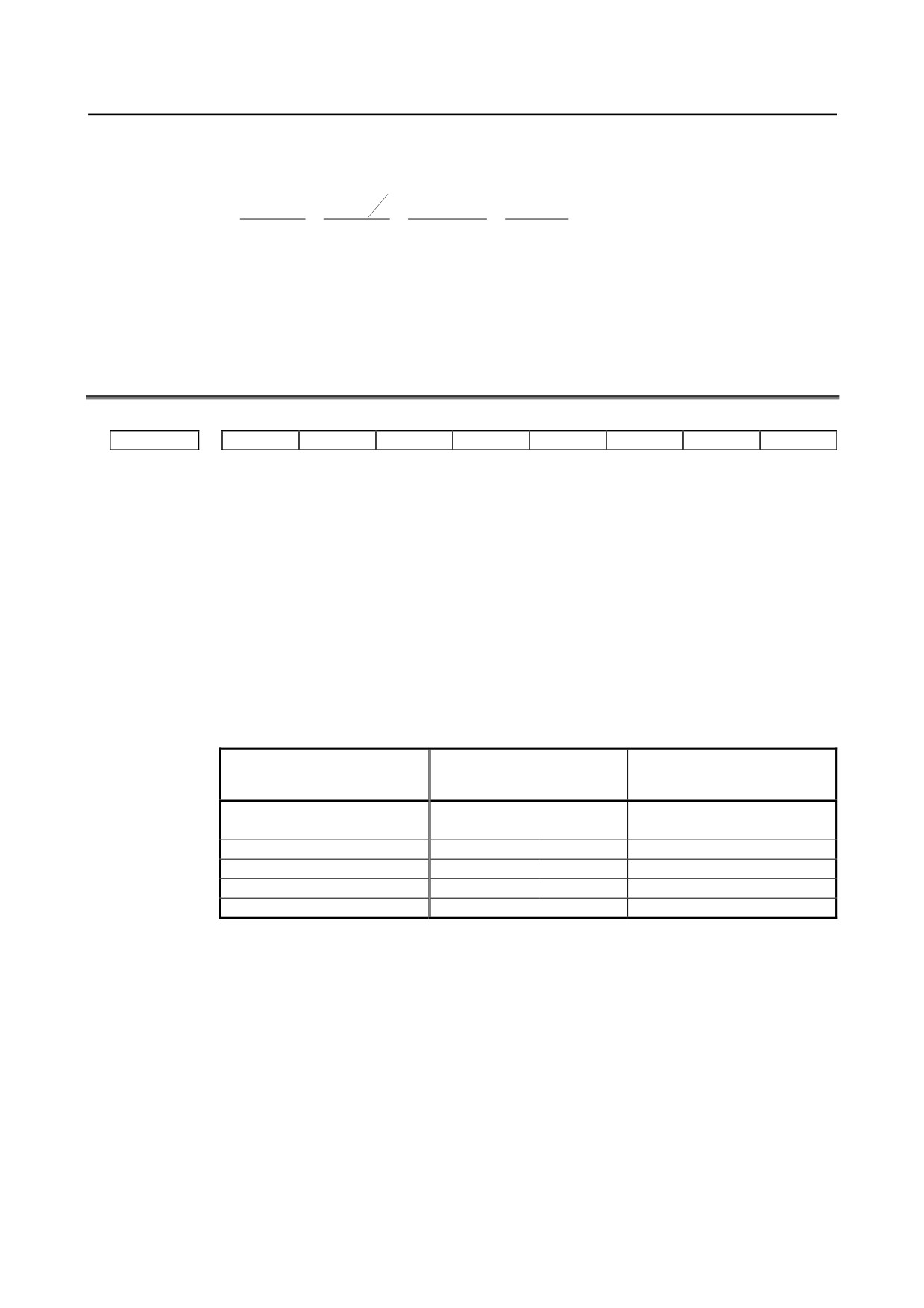
160000 cannot be divided by 3 without a remainder. In this case, change the setting of
parameter No. 7773 so that the ratio of the settings of parameters Nos. 7772 and 7773
indicates the value you want to set.
160000
No.7772
3
160000
160000
=
=
=
No.7773
360000
360000
×
3
1080000
Therefore, set 160000 for parameter No. 7772 and 1080000 for parameter No. 7773.
As described above, all the settings of parameters Nos. 7772 and 7773 have to do is to
indicate the ratio correctly. So, you can reduce the fraction indicated by the settings. For
example, you may set 16 for parameter No. 7772 and 108 for parameter No. 7773 for this
case.
4.49 PARAMETERS OF AXIS CONTROL BY PMC (1 OF 2)
#7
#6
#5
#4
#3
#2
#1
#0
8001
SKE
AUX
NCC
RDE
OVE
MLE
[Input type] Parameter input
[Data type] Bit path
#0 MLE Whether all axis machine lock signal MLK is valid for PMC-controlled axes
0: Valid
1: Invalid
The axis-by-axis machine lock signal MLKx depends on the setting of bit 1 of parameter
No. 8006.
#2 OVE Signals related to dry run and override used in PMC axis control
0: Same signals as those used for the CNC
1: Signals specific to the PMC
The signals used depend on the settings of these parameter bits as indicated below.
No.8001#2=0
No.8001#2=1
Signals
(same signals as those
(signals specific to the PMC)
used for the CNC)
*EFOV0 to
Feedrate override signals
*FV0 to *FV7
G012
G151
*EFOV7
Override cancellation signal
OVC
G006.
EOVC
G150.5
Rapid traverse override signals
ROV1,2
G014.0, .1
EROV1,2
G150.0, .1
Dry run signal
DRN
G46.7
EDRN
G150.7
Rapid traverse selection signal
RT
G19.7
ERT
G150.6
(The signal addresses at PMC selection time are for the group A.)
#3 RDE Whether dry run is valid for rapid traverse in PMC axis control
0: Invalid
1: Valid
#5 NCC When the program specifies a move command for a PMC-controlled axis (with the
controlled axis selection signal *EAX set to 1) not placed under PMC axis control:
0: CNC command is valid.
1: The alarm (PS0130) is issued.
#6 AUX In PMC axis control, the auxiliary function command (12H) output size is:
0:
1 byte (0 to 255)
1:
2 bytes (0 to 65535)
- 314 -
B-64310EN/02
4.DESCRIPTION OF PARAMETERS
#7 SKE Skip signal during axis control by the PMC
0: Uses the same signal SKIP <X004.7 or X013.7> as CNC.
1: Uses dedicated axis control signal ESKIP <X004.6 or X013.6> used by the PMC.
#7
#6
#5
#4
#3
#2
#1
#0
8002
FR2
FR1
PF2
PF1
F10
DWE
RPD
[Input type] Parameter input
[Data type] Bit path
#0 RPD Rapid traverse rate for PMC-controlled axes
0: Feedrate specified with parameter No.1420
1: Feedrate specified with the feedrate data in an axis control command by PMC
#1 DWE Minimum time which can be specified in a dwell command in PMC axis control when the
increment system is IS-C
0:
1ms
1:
0.1ms
#3 F10 Least increment for the feedrate for cutting feed (per minute) in PMC axis control
The following settings are applied when bit 4 (PF1) of parameter No. 8002 is set to 0 and
bit 5 (PF2) of parameter No. 8002 is set to 0.
F10
IS-A
IS-B
IS-C
Millimeter input
0
10
1
0.1
(mm/min)
1
100
10
1
Inch input
0
0.1
0.01
0.001
(inch/min)
1
1
0.1
0.01
#4 PF1
#5 PF2 Set the feedrate unit of cutting feedrate (feed per minute) for an axis controlled by the
PMC.
Bit 5 (PF2) of parameter No. 8002
Bit 4 (PF1) of parameter No. 8002
Feedrate unit
0
0
1 / 1
0
1
1 / 10
1
0
1 / 100
1
1
1 / 1000
#6 FR1
#7 FR2 Set the feedrate unit for cutting feedrate (feed per rotation) for an axis controlled by the
PMC.
Bit 7 (FR2) of parameter
Bit 6 (FR1) of parameter
Millimeter input
Inch input
No. 8002
No. 8002
(mm/rev)
(inch/rev)
0
0
0.0001
0.000001
1
1
0
1
0.001
0.00001
1
0
0.01
0.0001
#7
#6
#5
#4
#3
#2
#1
#0
8003
FEXx
[Input type] Parameter input
[Data type] Bit axis
- 315 -
4.DESCRIPTION OF PARAMETERS
B-64310EN/02
NOTE
When this parameter bit is set, the power must be turned off before
operation is continued.
#3
FEXx The maximum feedrate that can be achieved by the machine during cutting feed or
continuous feed in PMC axis control is:
0: Not extended.
1: Extended.
Restrictions
• Parameters for setting the time constants for linear acceleration/deceleration after
interpolation and bell-shaped acceleration/deceleration after interpolation
When as the acceleration/deceleration type, linear acceleration/ deceleration after
interpolation or bell-shaped acceleration/ deceleration after interpolation is used for
each of rapid traverse, cutting feed, and manual feed, the maximum allowable time
constant is a half of the maximum value that can be set conventionally.
The time constant parameters used are as follows:
Parameter No.
Meaning
1620
Time constant (T) used for linear acceleration/deceleration in rapid traverse for
each axis, or time constant (T1) used for bell-shaped acceleration/deceleration
in rapid traverse for each axis
1621
Time constant (T2) used for bell-shaped acceleration/deceleration in rapid
traverse for each axis
1622
Time constant for acceleration/deceleration in cutting feed for each axis
1624
Time constant for acceleration/deceleration in jog feed for each axis
1626
Time constant for acceleration/deceleration in threading cycles for each axis
1769
Time constant for acceleration/deceleration after cutting feed interpolation in
the mode of acceleration/deceleration before interpolation
5271 to 5274
Time constant for acceleration/deceleration in rigid tapping extraction (first to
fourth gears)
5365 to 5368
Time constant for bell-shaped acceleration/deceleration in rigid tapping (first to
fourth gears)
• VCMD waveform display function
As the feedrate increases, more data is acquired for VCMD waveform display,
which can prevent waveforms from being displayed correctly.
CAUTION
1 When this function is enabled, the feedrate is extended to the
maximum value that can be specified for cutting feed or continuous
feed in PMC axis control if CMR is 1. If CMR is greater than 1, the
feedrate is limited to a value smaller than the maximum value that
can be specified.
2 Note that the maximum motor speed may be exceeded depending
on the feedrate specified.
#7
#6
#5
#4
#3
#2
#1
#0
8004
NCI
DSL
JFM
[Input type] Parameter input
[Data type] Bit path
#2 JFM This parameter sets the units used to specify feedrate data when continuous feed is
specified in axis control by the PMC.
- 316 -
B-64310EN/02
4.DESCRIPTION OF PARAMETERS
Increment
Bit 2 (JFM) of
Millimeter input
Inch input
Rotation axis
system
No. 8004
(mm/min)
(inch/min)
(min-1)
0
1
0.01
0.00023
IS-B
1
200
2.00
0.046
0
0.1
0.001
0.000023
IS-C
1
20
0.200
0.0046
#5 DSL If the selection of an axis is changed when PMC axis selection is disabled:
0: An alarm PS0139 is issued.
1: The change is valid, and no alarm is issued for an unspecified group.
#6 NCI In axis control by the PMC, a position check at the time of deceleration is:
0: Performed.
1: Not performed.
#7
#6
#5
#4
#3
#2
#1
#0
8005
IFV
EVP
DRR
R10
CDI
EDC
[Input type] Setting input
[Data type] Bit path
#0 EDC In axis control by the PMC, an external deceleration function is:
0: Disabled.
1: Enabled.
#1 CDI In axis control by the PMC, when diameter programming is specified for a
PMC-controlled axis:
0: The amount of travel and feedrate are each specified with a radius.
1: The amount of travel is specified with a diameter while the feedrate is specified with
a radius.
This parameter is valid when bit 3 (DIA) of parameter No.1006 is set to 1 (A move
command for each axis is based on diameter specification.)
#2 R10 When the parameter RPD (bit 0 of parameter No.8002) is set to 1, the unit for specifying
a rapid traverse rate for the PMC axis is:
0:
1 mm/min.
1:
10mm/min.
#3 DRR For cutting feed per rotation in PMC axis control, the dry run function is:
0: Disabled.
1: Enabled.
#4 EVP Speed command in PMC axis control is executed by:
0: Velocity control.
1: Position control.
This bit is available when speed command in PMC axis control is FS0 type (parameter
VCP (No.8007#2) is 1).
#5 IFV When bit 2 (OVE) of parameter No. 8001 is set to 1 in PMC axis control, the feedrate
override signal *EFOVx and the override cancel signal EOVC are:
0: Used on a path-by-path basis. (The group A of each path are used.)
1: Used on a group-by-group basis.
- 317 -
4.DESCRIPTION OF PARAMETERS
B-64310EN/02
#7
#6
#5
#4
#3
#2
#1
#0
8006
EAL
EZR
EFD
MLS
[Input type] Parameter input
[Data type] Bit path
#1 MLS When bit 0 (MLE) of parameter No. 8001 is set to 1 (to disable the all axis machine lock
signal) in PMC axis control, axis-by-axis machine lock is:
0: Disabled.
1: Enabled.
#4 EFD When cutting feed (feed per minute) is used in PMC axis control, the specification unit of
feedrate data is:
0: Unchanged (1 times).
1:
100 times greater.
NOTE
When this parameter is set to 1, bit 3 (F10) of parameter No. 8002
is invalid.
#6 EZR In PMC axis control, bit 0 (ZRNx) of parameter No. 1005 is:
0: Invalid.
With a PMC controlled axis, the alarm (PS0224) is not issued.
1: Valid.
A reference position return state check is made on a PMC controlled axis as with an
NC axis according to the setting of bit 0 (ZRNx) of parameter No. 1005.
#7 EAL In PMC axis control, resetting the CNC:
0: Does not release an alarm on the PMC controlled axis
1: Releases an alarm on the PMC controlled axis
If an alarm on the PMC controlled axis is released, the PCM controlled axis alarm
signal (EIALg) is set to 0.
#7
#6
#5
#4
#3
#2
#1
#0
8007
ESY
VCP
[Input type] Parameter input
[Data type] Bit path
#2 VCP Speed command in PMC axis control is:
0: FS10/11 type.
1: FS0 type.
#3 ESY In PMC axis control, external pulse synchronization (serial spindle synchronization) is:
0: Disabled.
1: Enabled.
#7
#6
#5
#4
#3
#2
#1
#0
8008
EMRx
[Input type] Parameter input
[Data type] Bit axis
- 318 -
B-64310EN/02
4.DESCRIPTION OF PARAMETERS
#0 EMRx When a PMC axis control command is issued in mirror image state, the mirror image is:
0: Not considered.
1: Considered.
This parameter is valid in the mirror image mode set with the mirror image signals MI1 to
MI5 <G106.0 to 4> set to 1 or bit 0 (MIRx) of parameter No. 12 set to 1.
If a movement is made along the same axis by doubly specifying a command with the
CNC and PMC axis control when this parameter is set to 0, and the mirror image mode is
set, a coordinate shift can occur afterwards. So, do not attempt to make such a movement.
8010
Selection of the DI/DO group for each axis controlled by the PMC
[Input type] Parameter input
[Data type] Byte axis
[Valid data range] T series: 1 to 4 (at 1-path control), 1 to 8 (at 2-path control)
M series: 1 to 4
Specify the DI/DO group to be used to specify a command for each PMC-controlled axis.
P8010
Description
1
Uses path 1 DI/DO group A (G142 to G153)
2
Uses path 1 DI/DO group B (G154 to G165)
3
Uses path 1 DI/DO group C (G166 to G177)
4
Uses path 1 DI/DO group D (G178 to G189)
5
Uses path 2 DI/DO group A (G1142 to G1153)
6
Uses path 2 DI/DO group B (G1154 to G1165)
7
Uses path 2 DI/DO group C (G1166 to G1177)
8
Uses path 2 DI/DO group D (G1178 to G1189)
NOTE
Use path 1 DI/DO (1 to 4) for the axes controlled by path 1.
Use path 2 DI/DO (5 to 8) for the axes controlled by path 2.
#7
#6
#5
#4
#3
#2
#1
#0
8013
R20x
ROPx
[Input type] Parameter input
[Data type] Bit axis
#3 ROPx When rotation axis rollover is enabled for an axis controlled in PMC axis control, the
direction in which a movement (rotation) is performed to reach an end point by a
reference position return command 07H to 0AH (equivalent to G28, G30P2/P3/P4) is:
0: Determined by the sign of the specified value.
1: The direction in the shortest path.
NOTE
ROPx is valid only when bit 0 (ROAx) of parameter No. 1008 is set
to 1 and bit 1 (RABx) of parameter No. 1008 is set to 0.
#4 R20x When the machine coordinate system selection (20h) is commanded with the PMC axis
control for the rotary axis to which the roll-over function is valid (bit 0 (ROAx) of
parameter No.1008 is set to 1), setting the bit 1 (RABx) of parameter No.1008 which
specifies the direction of the rotation for an absolute command is:
0: Invalid.
1: Valid.
- 319 -
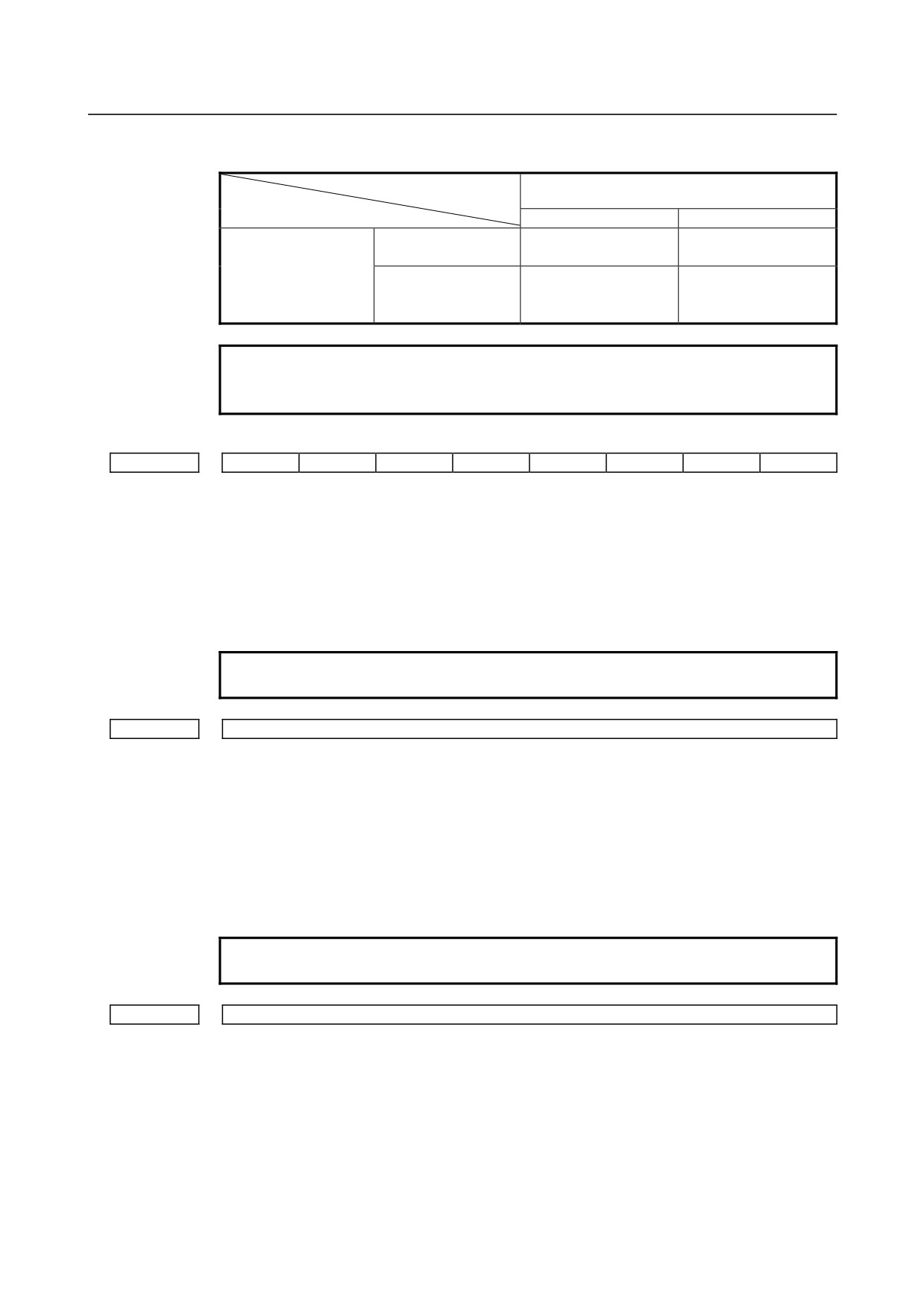
4.DESCRIPTION OF PARAMETERS
B-64310EN/02
The above direction of the rotation is as follows by setting the bit 1 (RABx) of parameter
No.1008 and the bit 4 (R20x) of parameter No.8013.
Bit 4 (R20x) of parameter No.8013
0
1
Direction of the
Direction of the
0
shortest path
shortest path
Bit 1 (RABx) of
Direction of sign of the
parameter No.1008
Direction of sign of the
1
amount of the
command value
movement to be made
NOTE
When "1" is set to R20x, the direction of the rotation is the same as
FS0i-C.
#7
#6
#5
#4
#3
#2
#1
#0
8019
EOS
[Input type] Parameter input
[Data type] Bit
#0 EOS In external pulse synchronization (serial spindle synchronization) in PMC axis control,
the serial spindle to be synchronized is:
0: The first spindle of path 1.
1: Any spindle.
NOTE
If EOS is set to 0, only the servo axis of path 1 can be specified.
8020
FL feedrate for reference position return along each axis in PMC axis control
[Input type] Parameter input
[Data type] Real axis
[Unit of data] mm/min, inch/min, degree/min (machine unit)
[Min. unit of data] Depend on the increment system of the applied axis
[Valid data range] Refer to the standard parameter setting table (C)
(When the increment system is IS-B, 0.0 to +999000.0)
For each axis, this parameter sets a feedrate (FL feedrate) after deceleration for reference
position return in PMC axis control.
NOTE
If 0 is specified, the value of parameter No. 1425 is used.
8022
Upper limit rate of feed per revolution during PMC axis control
[Input type] Parameter input
[Data type] Real axis
[Unit of data] mm/min, inch/min, degree/min (machine unit)
[Min. unit of data] Depend on the increment system of the applied axis
[Valid data range] Refer to the standard parameter setting table (C)
(When the increment system is IS-B, 0.0 to +999000.0)
This parameter sets the upper limit rate of feed per revolution during PMC axis control.
- 320 -
B-64310EN/02
4.DESCRIPTION OF PARAMETERS
8028
Time for acceleration/deceleration calculation when a feedrate is specified under PMC axis control
[Input type] Parameter input
[Data type] Word axis
[Unit of data] msec
[Valid data range] 0 to 32767
When a feedrate is specified under PMC axis control, acceleration/deceleration can be set
for parameter No. 8032 or this parameter. When 0 is set in parameter No. 8032, the
specification of
1000 min-1 is assumed. When
0 is set in this parameter, the
acceleration/deceleration function for feedrate specification is disabled.
Time constant for exponential acceleration/deceleration in cutting feed or continuous feed under PMC
8030
axis control
[Input type] Parameter input
[Data type] 2-word axis
[Unit of data] msec
[Valid data range] 0 to 4000
For each axis, this parameter sets a time constant for exponential
acceleration/deceleration in cutting feed or continuous feed under PMC axis control.
NOTE
When 0 is set in this parameter, the value set in parameter No.
1622 is used.
The value set in parameter No. 1622 is used also for linear
acceleration/deceleration after cutting interpolation.
FL feedrate for exponential acceleration/deceleration in cutting feed or continuous feed under PMC
8031
axis control
[Input type] Parameter input
[Data type] Real axis
[Unit of data] mm/min, inch/min, degree/min (machine unit)
[Min. unit of data] Depend on the increment system of the applied axis
[Valid data range] Refer to the standard parameter setting table (C)
(When the increment system is IS-B, 0.0 to +999000.0)
For each axis, this parameters sets a lower feedrate limit (FL feedrate) for exponential
acceleration/deceleration in cutting feed or continuous feed under PMC axis control.
NOTE
When 0 is set in this parameter, the value set in parameter No.
1623 is used.
However, be sure to set 0 in this parameter and parameter No.
1623 for all axes at all times except for special purposes. If a value
other than 0 is specified, correct linear or circular figures cannot be
obtained.
8032
Feedrate for acceleration/deceleration calculation when a feedrate is specified under PMC axis control
[Input type] Parameter input
[Data type] Word axis
[Unit of data] min-1
[Valid data range] 0 to 32767
- 321 -
4.DESCRIPTION OF PARAMETERS
B-64310EN/02
When a feedrate is specified under PMC axis control, acceleration/deceleration can be set
for this parameter or parameter No.
8028. When 0 is set in this parameter, the
specification of
1000 min-1 is assumed. When 0 is set in parameter No. 8028, the
acceleration/deceleration function for feedrate specification is disabled.
Amount of a shift per one rotation of a servo motor of least input increment
8040
when speed command in PMC axis control is velocity control
[Input type] Parameter input
[Data type] 2-word axis
[Unit of data] mm, inch, degree (machine unit)
[Valid data range] 1 to 99999999
Set the amount of a shift per one rotation of a servo motor of least input increment
when speed command in PMC axis control is velocity control.
This parameter is available when speed command in PMC axis control is FS0 type
(parameter VCP (No.8007#2) is 1) and is executed by position control (parameter EVP
(No.8005#4) is 1).
4.50 PARAMETERS OF 2-PATH CONTROL (T SERIES)
#7
#6
#5
#4
#3
#2
#1
#0
DSB
IAL
RST
8100
[Input type] Parameter input
[Data type] Bit machine group
#0 RST The pressing of the reset key on the MDI panel is:
0: Valid for two paths.
1: Valid only for the path selected by the path selection signal.
#1 IAL Choice of an option concerning operation continuation when an alarm is issued, and
choice of an option concerning the start of automatic operation in alarm state:
0: • When an alarm is issued, the operation is stopped with the other path(s) in same
group placed in hold state.
• When the other path or paths in same group are placed in alarm state, automatic
operation cannot be started.
1: • Even when an alarm is issued, the operation is continued without stopping the other
path(s).
• Even when the other path or paths in same group are placed in alarm state, automatic
operation can be started.
#6 DSB The inter-path single block check function is:
0: Disabled.
If one of the paths undergoes a single block stop, only the path undergoes a single
block stop.
1: Enabled.
If one of the paths undergoes a single block stop, the other path undergoes a feed
hold stop.
#7
#6
#5
#4
#3
#2
#1
#0
MWT
8103
[Input type] Parameter input
- 322 -