FANUC Series 0i-MODEL D, Series 0i Mate-MODEL D. PARAMETER MANUAL - page 9
B-64310EN/02
4.DESCRIPTION OF PARAMETERS
NOTE
These parameters are enabled when the parameter TDR (bit 2 of
parameter No.5201) is set to 1.
5280
Position control loop gain for the spindle and tapping axis in rigid tapping (common to gears)
Position control loop gain for the spindle and tapping axis in rigid tapping
5281
(first gear)
Position control loop gain for the spindle and tapping axis in rigid tapping
5282
(second gear)
Position control loop gain for the spindle and tapping axis in rigid tapping
5283
(third gear)
Position control loop gain for the spindle and tapping axis in rigid tapping
5284
(fourth gear)
[Input type] Parameter input
[Data type] Word spindle
[Unit of data] 0.01/sec
[Valid data range] 1 to 9999
Each of these parameters is used to set a position control loop gain for the spindle and
tapping axis in rigid tapping. These parameters significantly affect the precision of
threading. Conduct cutting tests, and make adjustments to obtain an optimum value.
When performing threading with an analog spindle, also adjust the loop gain multipliers
(parameter Nos. 5291 to 5294).
NOTE
To use a varied loop gain on a gear-by-gear basis, set parameter
No.5280 to 0, and set a loop gain for each gear in parameters
No.5281 to No.5284. The specification of a loop gain on a
gear-by-gear basis is disabled if parameter No.5280 is set to a
value other than 0. In such a case, the value set in parameter
No.5280 is used as a loop gain that is common to all the gears.
5291
Loop gain multiplier for the spindle in rigid tapping (first gear)
5292
Loop gain multiplier for the spindle in rigid tapping (second gear)
5293
Loop gain multiplier for the spindle in rigid tapping (third gear)
Loop gain multiplier for the spindle in rigid tapping (fourth gear)
5294
[Input type] Parameter input
[Data type] Word spindle
[Valid data range] 1 to 32767
Each of these parameters is used to set a loop gain multiplier for the spindle in rigid
tapping each gear.
These parameters significantly affect the precision of threading. Optimize these
parameters as well as the loop gains by conducting a cutting test.
Loop gain multiplier GC is obtained from the following equation:
- 233 -
4.DESCRIPTION OF PARAMETERS
B-64310EN/02
2048000×360×PC×E
GC
=
PLS
×
SP ×
L
PLS Number of pulses output from the position coder (pulses/rev)
SP Number of gear teeth on the spindle side
PC Number of gear teeth on the position coder side
E Specified voltage (V) for turning the spindle motor at 1000 min-1
L Angular displacement of the spindle (degrees) per spindle motor rotation
[Example] For the spindle motor and gear ratio given below, GC is calculated as follows:
2048000×360×1×
GC
=
= 1100
4096
×1
×
360
PLS = 4096 pulse/rev
SP
= 1
PC = 1
E
= 2.2 V
L
= 360 deg
NOTE
1 On the assumption that the spindle motor used turns at 4500 min-1
at 10 V, 2.2 V is required to turn the spindle motor at 1000 min-1
2 These parameters are used for analog spindles.
5300
Tapping axis in-position width in rigid tapping (first spindle)
[Input type] Parameter input
[Data type] Word axis
[Unit of data] Detection unit
[Valid data range] 0 to 32767
This parameter sets a tapping axis in-position width when rigid tapping is performed
using the first spindle.
NOTE
Set the following parameter for each spindle:
First spindle
No.5300
Second spindle
No.5302
5301
Spindle in-position width in rigid tapping
[Input type] Parameter input
[Data type] Word spindle
[Unit of data] Detection unit
[Valid data range] 0 to 32767
These parameters are used to set spindle in-position widths in rigid tapping.
NOTE
If an excessively large value is specified, the threading precision
will deteriorate.
5302
Tapping axis in-position width in rigid tapping (second spindle)
[Input type] Parameter input
[Data type] Word axis
[Unit of data] Detection unit
[Valid data range] 0 to 32767
- 234 -
B-64310EN/02
4.DESCRIPTION OF PARAMETERS
This parameter sets a tapping axis in-position width when rigid tapping is performed
using the second spindle.
5310
Positional deviation limit imposed during tapping axis movement in rigid tapping (first spindle)
[Input type] Parameter input
[Data type] 2-word axis
[Unit of data] Detection unit
[Valid data range] 0 to 99999999
This parameter sets a positional deviation limit imposed during tapping axis movement in
rigid tapping using the first spindle.
NOTE
Set the following parameter for each spindle:
First spindle
No.5310
Second spindle
No.5350
5311
Limit value of spindle positioning deviation during movement in rigid tapping
[Input type] Parameter input
[Data type] 2-word spindle
[Unit of data] Detection unit
[Valid data range] 0 to 99999999
This parameter sets the limit value of a spindle positioning deviation during movement in
rigid tapping.
Find a value to be set from the following expression:
S×PLS×100×SP×C
Setting value=
60×GP×C
S Maximum spindle speed in rigid tapping (min-1)
(Setting value of parameter Nos. 5241 and greater)
PLS Number of pulses output from the position coder (pulses/rev)
SP Number of gear teeth on the spindle side
PC Number of gear teeth on the position coder side
G Loop gain in the rigid tapping (0.01sec-1)
(Setting value of parameter Nos. 5281 and greater)
C Coefficient 1.5
(Calculation example)
SPINDLE
MOTOR
Position
Spindle
coder
10 : 10 : 20
S
= 3600
PLS = 4096
- 235 -
4.DESCRIPTION OF PARAMETERS
B-64310EN/02
SP
= 10
PC
= 20
G
= 3000
C
= 1.5
3600×4096×100×10×
Setting
value
=
= 6144
60
×
3000
×
20
5312
Positional deviation limit imposed while the tapping axis is stopped in rigid tapping (first spindle)
[Input type] Parameter input
[Data type] Word axis
[Unit of data] Detection unit
[Valid data range] 0 to 32767
This parameter sets a positional deviation limit imposed while the tapping axis is stopped
in rigid tapping using the first spindle.
NOTE
Set the following parameter for each spindle:
First spindle
No.5312
Second spindle
No.5352
5313
Positional deviation limit imposed while the spindle is stopped in rigid tapping
[Input type] Parameter input
[Data type] 2-word spindle
[Unit of data] Detection unit
[Valid data range] 0 to 99999999
This parameter is used to set a positional deviation limit imposed while the spindle is
stopped in rigid tapping.
5321
Spindle backlash in rigid tapping (first-stage gear)
5322
Spindle backlash in rigid tapping (second-stage gear)
5323
Spindle backlash in rigid tapping (third-stage gear)
Spindle backlash in rigid tapping (fourth-stage gear)
5324
[Input type] Parameter input
[Data type] Word spindle
[Unit of data] Detection unit
[Valid data range] -9999 to 9999
Each of these parameters is used to set a spindle backlash.
5350
Positional deviation limit imposed during tapping axis movement in rigid tapping (second spindle)
[Input type] Parameter input
[Data type] 2-word axis
[Unit of data] Detection unit
[Valid data range] 0 to 99999999
This parameter sets a positional deviation limit imposed during tapping axis movement in
rigid tapping using the second spindle.
- 236 -
B-64310EN/02
4.DESCRIPTION OF PARAMETERS
5352
Positional deviation limit imposed while the tapping axis is stopped in rigid tapping (second spindle)
[Input type] Parameter input
[Data type] Word axis
[Unit of data] Detection unit
[Valid data range] 0 to 32767
This parameter is used to set a positional deviation limit imposed while the tapping axis is
stopped in rigid tapping using the second spindle.
5365
Bell-shaped acceleration/deceleration time constant in rigid tapping (first-stage gear)
5366
Bell-shaped acceleration/deceleration time constant in rigid tapping (second-stage gear)
5367
Bell-shaped acceleration/deceleration time constant in rigid tapping (third-stage gear)
[Input type] Parameter input
[Data type] Word spindle
[Unit of data] msec
[Valid data range] 0 to 512
Each of these parameters is used to set a time constant for a curved portion when
bell-shaped acceleration/deceleration is selected in rigid tapping. When 0 is set in this
parameter, linear acceleration/ deceleration is performed.
NOTE
This parameter is enabled when the parameter RBL (bit 5 of
parameter No.5203) is set to 1.
5381
Override value during rigid tapping return
[Input type] Parameter input
[Data type] Word path
[Unit of data] %
[Valid data range] 0 to 200
This parameter is used to set the override value during rigid tapping return.
If the setting is 0, no override is applied.
NOTE
This parameter is valid when bit 4 (DOV) of parameter No. 5200 for
enabling override at normal extraction time is set to 1.
5382
Amount of return for rigid tapping return
[Input type] Parameter input
[Data type] Real path
[Unit of data] mm, inch (input unit)
[Min. unit of data] Depend on the increment system of the drilling axis
[Valid data range] 0 or positive 9 digit of minimum unit of data (refer to the standard parameter setting table
(B))
(When the increment system is IS-B, 0.0 to +999999.999)
- 237 -
4.DESCRIPTION OF PARAMETERS
B-64310EN/02
This parameter is used to set an extra amount of rigid tapping return. The tool is retracted
additionally near point R by the distance set in this parameter. If the tool has already been
retracted from rigid tapping, it will be retracted further only by the distance specified in
this parameter.
4.25 PARAMETERS OF SCALING (M SERIES) /COORDINATE
ROTATION (M SERIES)
#7
#6
#5
#4
#3
#2
#1
#0
5400
SCR
XSC
RIN
[Input type] Parameter input
[Data type] Bit path
#0 RIN Coordinate rotation angle command (R) :
0: Specified by an absolute method
1: Specified by an absolute method (G90) or incremental method (G91)
#6 XSC The setting of a scaling magnification (axis-by-axis scaling) is:
0: Disabled.
1: Enabled.
#7 SCR Scaling (G51) magnification unit:
0:
0.00001 times (1/100,000)
1:
0.001 times
#7
#6
#5
#4
#3
#2
#1
#0
5401
SCLx
[Input type] Parameter input
[Data type] Bit axis
#0 SCLx Scaling on this axis:
0: Invalidated
1: Validated
5410
Angular displacement used when no angular displacement is specified for coordinate system rotation
[Input type] Setting input
[Data type] 2-word path
[Unit of data] 0.001 degree
[Valid data range] -360000 to 360000
This parameter sets the angular displacement for coordinate system rotation. When the
angular displacement for coordinate system rotation is not specified with address R in the
block where G68 is specified, the setting of this parameter is used as the angular
displacement for coordinate system rotation.
5411
Scaling (G51) magnification
[Input type] Setting input
- 238 -
B-64310EN/02
4.DESCRIPTION OF PARAMETERS
[Data type] 2-word path
[Unit of data] 0.001 or 0.00001 times (Selected using SCR, #7 of parameter No.5400)
[Valid data range] 1to999999999
This parameter sets a scaling magnification when axis-by-axis scaling is disabled (with
bit 6 (XSC) of parameter No. 5400 set to 0). If no scaling magnification (P) is specified in
the program, the setting of this parameter is used as a scaling magnification.
NOTE
When bit 7 (SCR) of parameter No.5400 is set to 1, the valid data
range is 1 to 9999999.
5421
Scaling magnification for each axis
[Input type] Setting input
[Data type] 2-word axis
[Unit of data] 0.001 or 0.00001 times (Selected using SCR, #7 of parameter No.5400)
[Valid data range] -999999999 to -1, 1 to 999999999
This parameter sets a scaling magnification for each axis when axis-by-axis scaling is
enabled (with bit 6 (XSC) of parameter No. 5400 set to 1). For the first spindle to the
third spindle
(X-axis to Z-axis), the setting of this parameter is used as a scaling
magnification if scaling magnifications (I, J, K) are not specified in the program.
NOTE
When bit 7 (SCR) of parameter No.5400 is set to 1, the valid data
ranges are -9999999 to -1 and 1 to 9999999.
4.26 PARAMETERS OF SINGLE DIRECTIONAL POSITIONING
(M SERIES)
#7
#6
#5
#4
#3
#2
#1
#0
5431
PDI
MDL
[Input type] Parameter input
[Data type] Bit path
NOTE
When at least one of these parameters is set, the power must be
turned off before operation is continued.
#0 MDL The G60 code (one-direction positioning) is:
0: One-shot G code (group 00).
1: Modal G code (group 01).
#1 PDI In the G60 mode, an in-position check at a stop position is:
0: Not made.
1: Made.
- 239 -
4.DESCRIPTION OF PARAMETERS
B-64310EN/02
5440
Positioning direction and overrun distance in single directional positioning
[Input type] Parameter input
[Data type] Real axis
[Unit of data] mm, inch, degree (machine unit)
[Min. unit of data] Depend on the increment system of the applied axis
[Valid data range] 9 digit of minimum unit of data (refer to standard parameter setting table (A))
(When the increment system is IS-B, -999999.999 to +999999.999)
This parameter sets the positioning direction and overrun distance in single directional
positioning (G60) for each axis. The positioning direction is specified using a setting data
sign, and the overrun distance using a value set here.
Overrun distance>0: The positioning direction is positive (+).
Overrun distance<0: The positioning direction is negative (*).
Overrun distance=0: Single directional positioning is not performed.
4.27 PARAMETERS OF POLAR COORDINATE
INTERPOLATION (T SERIES)
#7
#6
#5
#4
#3
#2
#1
#0
PLS
PDI
5450
[Input type] Parameter input
[Data type] Bit path
#0 PDI When the second axis on the plane in the polar coordinate interpolation mode is based on
radius specification:
0: Radius specification is used.
1: Diameter specification is used.
#2 PLS The polar coordinate interpolation shift function is:
0: Not used.
1: Used.
This enables machining using the workpiece coordinate system with a desired point
which is not the center of the rotation axis set as the origin of the coordinate system in
polar coordinate interpolation.
Axis (linear axis) specification for polar coordinate interpolation
5460
[Input type] Parameter input
[Data type] Byte path
[Valid data range] 1 to number of controlled axes
This parameter sets control axis numbers of linear axis to execute polar interpolation.
Axis (rotation axis) specification for polar coordinate interpolation
5461
[Input type] Parameter input
[Data type] Byte path
[Valid data range] 1 to number of controlled axes
This parameter sets control axis numbers of rotation axis to execute polar interpolation.
- 240 -
B-64310EN/02
4.DESCRIPTION OF PARAMETERS
Automatic override tolerance ratio for polar coordinate interpolation
5463
[Input type] Parameter input
[Data type] Byte path
[Unit of data] %
[Valid data range] 0 to 100
Typical setting: 90% (treated as 90% when set to 0)
Set the tolerance ratio of the fastest cutting feedrate to the speed of the rotation axis
during automatic override of polar coordinate interpolation.
Compensation for error on hypothetical axis of polar coordinate interpolation
5464
[Input type] Parameter input
[Data type] Byte path
[Unit of data] mm, inch (input unit)
[Min. unit of data] Depend on the increment system of the reference axis
[Valid data range] 9 digit of minimum unit of data (refer to standard parameter setting table (A))
(For IS-B, -999999.999 to +999999.999)
This parameter is used to set the error if the center of the rotation axis on which polar
coordinate interpolation is performed is not on the X-axis.
If the setting of the parameter is 0, regular polar coordinate interpolation is performed.
4.28 PARAMETERS OF NORMAL DIRECTION CONTROL (M
SERIES)
5480
Number of the axis for controlling the normal direction
[Input type] Parameter input
[Data type] Byte path
[Valid data range] 1 to the maximum controlled axis number
This parameter sets the controlled axis number of the axis for controlling the normal
direction.
5481
Feedrate of rotation of the normal direction controlled axis
[Input type] Parameter input
[Data type] Real axis
[Unit of data] deg/min
[Min. unit of data] Depend on the increment system of the applied axis
[Valid data range] Refer to the standard parameter setting table (C)
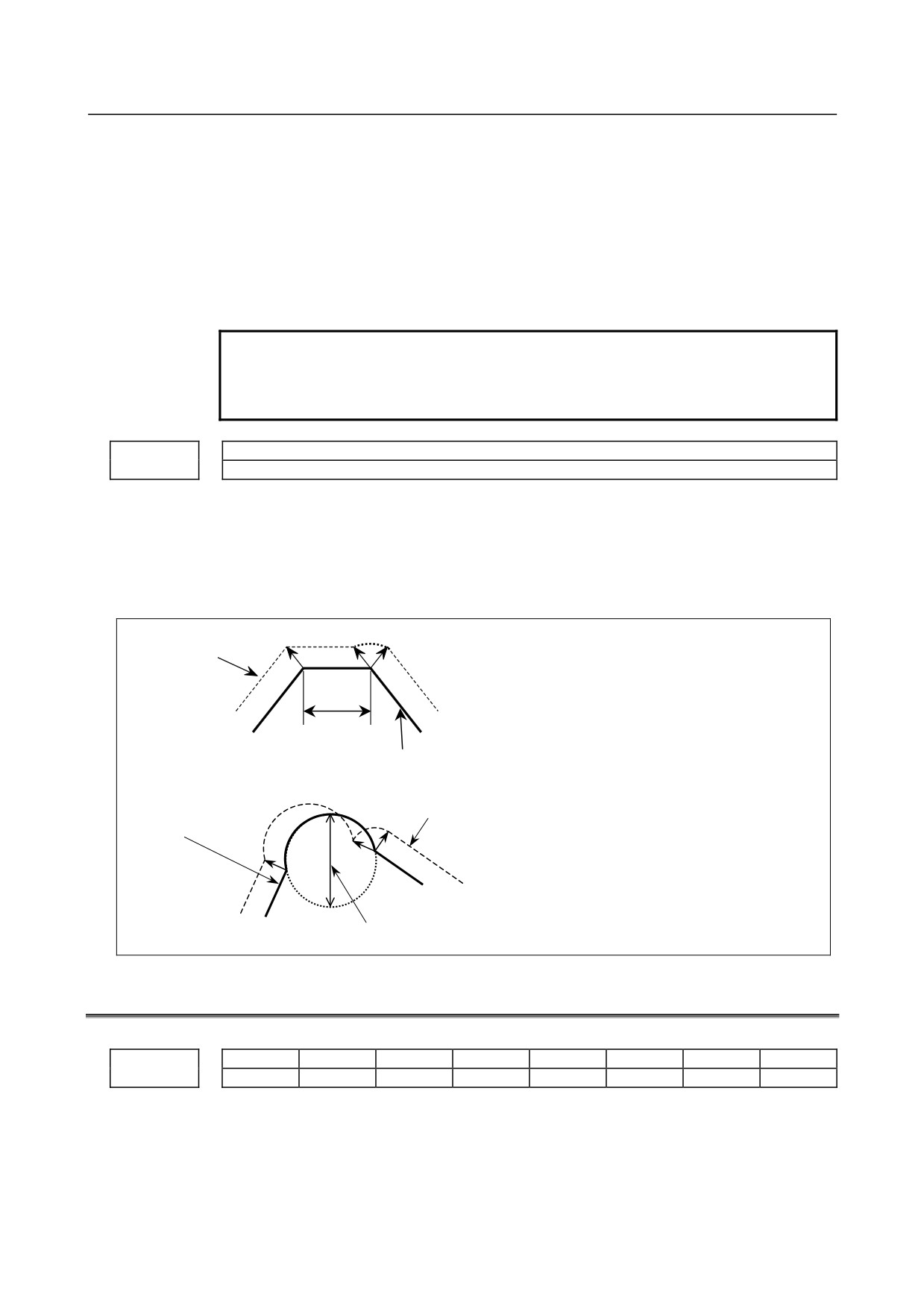
This parameter sets the feedrate of the movement along the normal direction controlled
axis that is inserted at the start point of a block during normal direction control.
5482
Limit value used to determine whether to ignore the rotation insertion of the normal direction
controlled axis
[Input type] Parameter input
[Data type] Real path
[Unit of data] Degree
- 241 -
4.DESCRIPTION OF PARAMETERS
B-64310EN/02
[Min. unit of data] Depend on the increment system of the reference axis
[Valid data range] 0 or positive 9 digit of minimum unit of data (refer to the standard parameter setting table
(B))
(For IS-B, -999999.999 to +999999.999)
The rotation block of the normal direction controlled axis is not inserted when the
rotation insertion angle calculated during normal direction control does not exceed this
setting.
The ignored rotation angle is added to the next rotation insertion angle, and the block
insertion is then judged.
NOTE
1 No rotation block is inserted when 360 or more degrees are set.
2 If 180 or more degrees are set, a rotation block is inserted only
when the circular interpolation setting is 180 or more degrees.
5483
Limit value of movement that is executed at the normal direction angle of a preceding block
[Input type] Parameter input
[Data type] Real path
[Unit of data] mm, inch (input unit)
[Min. unit of data] Depend on the increment system of the reference axis
[Valid data range] 0 or positive 9 digit of minimum unit of data (refer to standard parameter setting table (B)
(For IS-B, -999999.999 to +999999.999)
N2
Tool center path
For straight line
When the travel distance of N2 in the figure on
N3
the left does not exceed the setting, block N2 is
N1
machined with the tool being normal to block N1.
Travel distance
Programmed path
N2
Tool center path
Programmed path
For arc
N3
When the arc diameter of N2 in the figure on
the left does not exceed the setting, arc N2 is
machined with the tool being normal to block
N1. A normal direction axis is not controlled to
N1
move in the normal direction according to the
Diameter
arc movement.
4.29 PARAMETERS OF INDEX TABLE INDEXING (M SERIES)
#7
#6
#5
#4
#3
#2
#1
#0
5500
IDX
SIM
G90
INC
ABS
REL
DDP
[Input type] Parameter input
[Data type] Bit path
- 242 -
B-64310EN/02
4.DESCRIPTION OF PARAMETERS
#0 DDP As the method for inputting a decimal point in a command for the index table indexing
axis:
0: The conventional method is used. (Example IS-B: B1; = 0.001 deg)
1: The pocket calculator method is used. (Example IS-B: B1; = 1.000 deg)
#1 REL The position display of the index table indexing axis in the relative coordinate system is:
0: Not rounded by one rotation.
1: Rounded by one rotation.
#2 ABS The position display of the index table indexing axis in the absolute coordinate system is:
0: Not rounded by one rotation.
1: Rounded by one rotation.
#3 INC When the M code that specifies rotation in the negative direction (parameter No.5511) is
not set, rotation in the G90 mode is:
0: Not set to the shorter way around the circumference.
1: Set to the shorter way around the circumference. (Set bit 2 (ABS) of parameter
No.5500, to 1.)
#4 G90 A command for the index table indexing axis is:
0: Assumed to be an absolute or incremental command according to the mode.
1: Always assumed to be an absolute command.
#6 SIM When the same block includes a command for the index table indexing axis and a
command for another controlled axis:
0: The setting of bit 0 (IXS) of parameter No.5502 is followed.
1: The commands are executed.
NOTE
Even when this parameter is set to 1, an alarm (PS1564) is issued
if the block is neither G00, G28, nor G30 (or the G00 mode).
#7 IDX Operation sequence of the index table indexing axis:
0: Type A
1: Type B
#7
#6
#5
#4
#3
#2
#1
#0
5501
ISP
ITI
[Input type] Parameter input
[Data type] Bit path
#0 ITI The index table indexing function is:
0: Enabled.
1: Disabled.
NOTE
To enable the index table indexing function, set bit 3 (IXC) of
parameter No. 8132 to 1 in addition to this parameter. The index
table indexing function is enabled only when both ITI and IXC are
enabled.
- 243 -
4.DESCRIPTION OF PARAMETERS
B-64310EN/02
#1 ISP Servo-off for an index axis at the completion of clamping is:
0: Processed by the CNC.
1: Not processed by the CNC. (The CNC follows the status of the servo-off signal
<G0126> input from the PMC.)
#7
#6
#5
#4
#3
#2
#1
#0
5502
IXSx
[Input type] Parameter input
[Data type] Bit axis
#0 IXSx When a command is specified in a block that contains a command for the index table
indexing axis:
0 : An alarm (PS1564) is issued.
1 : The command is executed.
If bit 6 (SIM) of parameter No.5500 is set to 1, a simultaneous operation with all axes
except the index table indexing axis can be performed regardless of the setting of this
parameter.
To set an axis that allows simultaneous operation for each axis, set SIM to 0, and set this
parameter.
NOTE
Even when this parameter is set to 1, an alarm (PS1564) is issued
if the block is neither G00, G28, nor G30 (or the G00 mode).
5510
Controlled axis number of the index table indexing axis
NOTE
When this parameter is set, the power must be turned off before
operation is continued.
[Input type] Parameter input
[Data type] Byte path
[Valid data range] 0 to Number of controlled axes
This parameter sets the number of a controlled axis to be used as the index table indexing
axis.
When the setting value is 0, it is assumed that the fourth axis is the index table indexing
axis if the number of control axes is four or more,
and is assumed that the final axis is the index table indexing axis if the number of control
axes is three or less.
5511
M code that specifies rotation in the negative direction for index table indexing
[Input type] Parameter input
[Data type] 2-word path
[Valid data range] 0 to 99999999
0: The rotation direction for the index table indexing axis is determined according to
the setting of bit 3 (INC) of parameter No.5500 and a command.
1 to 99999999:
- 244 -
B-64310EN/02
4.DESCRIPTION OF PARAMETERS
The rotation for the index table indexing axis is always performed in the positive
direction. Rotation in the negative direction is performed only when the M code
set in this parameter is specified together with a movement command.
NOTE
Be sure to set bit 2 (ABS) of parameter No.5500 to 1.
5512
Minimum positioning angle for the index table indexing axis
[Input type] Parameter input
[Data type] Real path
[Unit of data] deg
[Min. unit of data] Depend on the increment system of the reference axis
[Valid data range] 9 digit of minimum unit of data (refer to standard parameter setting table (A))
(When the increment system is IS-B, -999999.999 to +999999.999)
This parameter sets the minimum positioning angle (travel distance) for the index table
indexing axis. The travel distance specified in the positioning command must always be
an integer multiple of this setting. When 0 is set, the travel distance is not checked.
The minimum positioning angle is checked not only for the command, but also for the
coordinate system setting and workpiece origin offset.
NOTE
When the setting is 0, specification can be performed regardless of
the minimum angle.
4.30 PARAMETERS OF SIMPLE STRAIGHTNESS
COMPENSATION (M SERIES)
5711
Simple straightness compensation : Axis number of moving axis 1
NOTE
When this parameter is set, the power must be turned off before
operation is continued.
[Input type] Parameter input
[Data type] Byte path
[Valid data range] 1 to number of controlled axes
Set the axis number of a moving axis in simple straight compensation.
When 0 is set, compensation is not performed.
5721
Simple straightness compensation :
Axis number of compensation axis 1 for moving axis 1
NOTE
When this parameter is set, the power must be turned off before
operation is continued.
[Input type] Parameter input
[Data type] Byte path
- 245 -
4.DESCRIPTION OF PARAMETERS
B-64310EN/02
[Valid data range] 1 to number of controlled axes
Set the axis number of a compensation axis in simple straight compensation.
When 0 is set, compensation is not performed.
5731
Simple straightness compensation : Compensation point number a of moving axis 1
5732
Simple straightness compensation : Compensation point number b of moving axis 1
5733
Simple straightness compensation : Compensation point number c of moving axis 1
5734
Simple straightness compensation : Compensation point number d of moving axis 1
NOTE
When these parameters are set, the power must be turned off before
operation is continued.
[Input type] Parameter input
[Data type] Word path
[Unit of data] Detection unit
[Valid data range] 0 to 1023
These parameters set compensation point numbers in stored pitch error compensation.
Set four compensation points for each moving axis.
5761
Compensation corresponding compensation point number a of moving axis 1
5762
Compensation corresponding compensation point number b of moving axis 1
5763
Compensation corresponding compensation point number c of moving axis 1
5764
Compensation corresponding compensation point number d of moving axis 1
NOTE
When these parameters are set, the power must be turned off before
operation is continued.
[Input type] Parameter input
[Data type] Word path
[Unit of data] Detection unit
[Valid data range] -32767 to 32767
Each of these parameters sets a compensation value for each moving axis compensation
point.
- 246 -
B-64310EN/02
4.DESCRIPTION OF PARAMETERS
4.31 PARAMETERS OF INCLINATION COMPENSATION
5861
Inclination compensation : Compensation point number a for each axis
5862
Inclination compensation : Compensation point number b for each axis
5863
Inclination compensation : Compensation point number c for each axis
5864
Inclination compensation : Compensation point number d for each axis
NOTE
When these parameters are set, the power must be turned off before
operation is continued.
[Input type] Parameter input
[Data type] Word axis
[Valid data range] 0 to 1023
These parameters set the compensation points for inclination compensation. The points
are set for the compensation point numbers for stored pitch error compensation.
5871
Inclination compensation : Compensation α at compensation point number a for each axis
5872
Inclination compensation : Compensation β at compensation point number b for each axis
5873
Inclination compensation : Compensation γ at compensation point number c for each axis
5874
Inclination compensation : Compensation δ at compensation point number d for each axis
NOTE
When these parameters are set, the power must be turned off before
operation is continued.
[Input type] Parameter input
[Data type] Word axis
[Unit of data] Detection unit
[Valid data range] -32767 to 32767
Each of these parameters sets a compensation value for each axis compensation point.
- 247 -
4.DESCRIPTION OF PARAMETERS
B-64310EN/02
4.32 PARAMETERS OF CUSTOM MACROS
#7
#6
#5
#4
#3
#2
#1
#0
SBV
SBM
HGO
MGO
G67
6000
SBV
SBM
HGO
V10
MGO
G67
[Input type] Parameter input
[Data type] Bit path
#0 G67 If the macro modal call cancel command (G67) is specified when the macro modal call
mode (G66) is not set:
0: Alarm PS0122 is issued.
1: The specification of G67 is ignored.
#1 MGO When a GOTO statement for specifying custom macro control is executed, a high-speed
branch to 20 sequence numbers executed from the start of the program is:
0: A high-speed branch is not caused to n sequence numbers from the start of the
executed program.
1: A high-speed branch is caused to n sequence numbers from the start of the program.
#3 V10 As system variable numbers for tool offset:
0 : The standard system variable numbers for the Series 0 are used.
1 : The same system variable numbers as those used for the Series 10/11 are used.
The tables below indicate the system variables for tool offset numbers 1 to 400. The
values for tool offset numbers 1 to 200 can be read from or assigned to the system
variables in parentheses.
(1) Tool offset memory A
System variable number
V10 = 0
V10 = 1
#10001 to #10400
#10001 to #10400
Wear offset value
(#2001 to #2200)
(#2001 to #2200)
(2) Tool offset memory C
System variable number
V10 = 0
V10 = 1
#11001 to #11400
#10001 to #10400
Wear offset value
Tool length
(#2201 to #2400)
(#2001 to #2200)
offset
#10001 to #10400
#11001 to #11400
Geometry offset value
(#2001 to #2200)
(#2201 to #2400)
Tool radius
Wear offset value
#13001 to #13400
#12001 to #12400
offset
Geometry offset value
#12001 to #12400
#13001 to #13400
#4 HGO When a GOTO statement in a custom macro control command is executed, a high-speed
branch to the 30 sequence numbers immediately before the executed statement is:
0: Not made.
1: Made.
#5 SBM Custom macro statement
0: Not stop the single block
1: Stops the single block
If you want to disable the single blocks in custom macro statements using system variable
#3003, set this parameter to 0. If this parameter is set to 1, the single blocks in custom
macro statements cannot be disabled using system variable #3003. To control single
blocks in custom macro statements using system variable #3003, use bit 7 (SBV) of
parameter No. 6000.
- 248 -
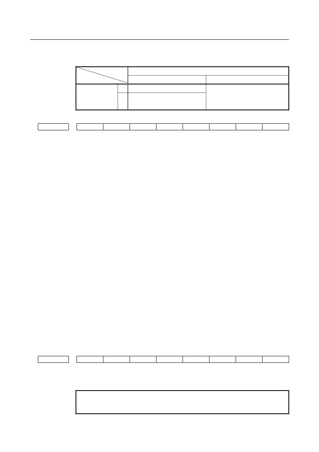
B-64310EN/02
4.DESCRIPTION OF PARAMETERS
#7 SBV Custom macro statement
0: Not stop the single block
1: Enable/disable single block stop with system variable #3003
Parameter SBM (No.6000#5)
0
1
Disables single block stop.
Enables single block stop. (With
0
Parameter SBV
variable #3003, single block stop
Enables single block stop. (With
(No.6000#7)
cannot be enabled/disabled. Single
1
variable #3003, single block stop
block stop is enabled at all times.)
can be enabled/disabled.)
#7
#6
#5
#4
#3
#2
#1
#0
6001
CCV
TCS
CRO
PV5
PRT
MIF
[Input type] Parameter input
[Data type] Bit path
#0 MIF The custom macro interface signals are based on:
0: Standard specification.
(The signals UI000 to UI015, UO000 to UO015, and UO100 to UO131 are used.)
1: Extended specification.
(The signals UI000 to UI031, UI100 to UI131, UI200 to UI231, UI300 to UI331,
UO000 to UO031, UO100 to UO131, UO200 to UO231, and UO300 to UO331 are
used.)
#1 PRT Reading zero when data is output using a DPRINT command
0: Outputs a space
1: Outputs no data
#3 PV5 Custom macro common variables:
0:
#500 to #999 are output.
1:
#100 to #199 and #500 to 999 are output.
#4 CRO ISO code in BPRWT or DPRNT command
0: Outputs only “LF” after data is output
1: Outputs “LF” and “CR” after data is output
#5 TCS Custom macro (subprogram)
0: Not called using a T code
1: Called using a T code
#6 CCV Common variables #100 to #199 cleared by power-off are:
0: Cleared to <null> by reset
1: Not cleared by reset
#7
#6
#5
#4
#3
#2
#1
#0
6003
MUS
MSB
MPR
TSE
MIN
MSK
[Input type] Parameter input
[Data type] Bit path
NOTE
When at least one of these parameters is set, the power must be
turned off before operation is continued.
- 249 -
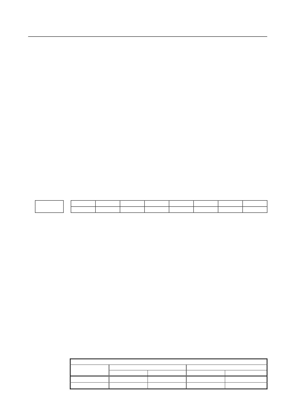
4.DESCRIPTION OF PARAMETERS
B-64310EN/02
#1 MSK Absolute coordinates at that time during custom macro interrupt
0: Not set to the skip coordinates (system variables #5061 and later)
1: Set to the skip coordinates (system variables #5061 and later)
#2 MIN Custom macro interrupt
0: Performed by interrupting an in-execution block (Custom macro interrupt type I)
1: Performed after an in-execution block is completed (Custom macro interrupt type II)
#3 TSE Custom macro interrupt signal UINT
0: Edge trigger method (Rising edge)
1: Status trigger method
#4 MPR Custom macro interrupt valid/invalid M code
0: M96/M97
1: M code set using parameters (Nos. 6033 and 6034)
#5 MSB Interrupt program
0: Uses a dedicated local variable (Macro-type interrupt)
1: Uses the same local variable as in the main program (Subprogram- type interrupt)
#7 MUS Interrupt-type custom macro
0: Not used
1: Used
#7
#6
#5
#4
#3
#2
#1
#0
VHD
NAT
6004
D10
NAT
[Input type] Parameter input
[Data type] Bit path
#0 NAT The results of the custom macro functions ATAN (with 2 arguments) and ASIN are
specified as follows:
0: The result of ATAN is 0 to 360.0.
The result of ASIN is 270.0 to 0 to 90.0.
1: The result of ATAN is -180.0 to 0 to 180.0.
The result of ASIN is -90.0 to 0 to 90.0.
#2 VHD With system variables #5121 to #5125:
0: The tool offset value (geometry offset value) in the block currently being executed is
read. (This parameter is valid only when tool geometry/tool wear compensation
memories are available (bit 6 (NGW) of parameter No. 8136 is 0)).
1: An interrupt travel distance based on manual handle interrupt is read.
#5 D10 When tool compensation memory C is used, for reading or writing tool offset values (for
up to offset number 200) for D code (tool radius), the same system variables, #2401
through #2800, as Series 10/11 are:
0: Not used.
1: Used.
When bit 3 (V10) of parameter No. 6000 is set to 1
D code
Compensation
Geometry
Wear
number
Variable number
Variable name
Variable number
Variable name
1
#2401
[#_OFSDG[1]]
#2601
[#_OFSDW[1]]
2
#2402
[#_OFSDG[2]]
#2602
[#_OFSDW[2]]
- 250 -
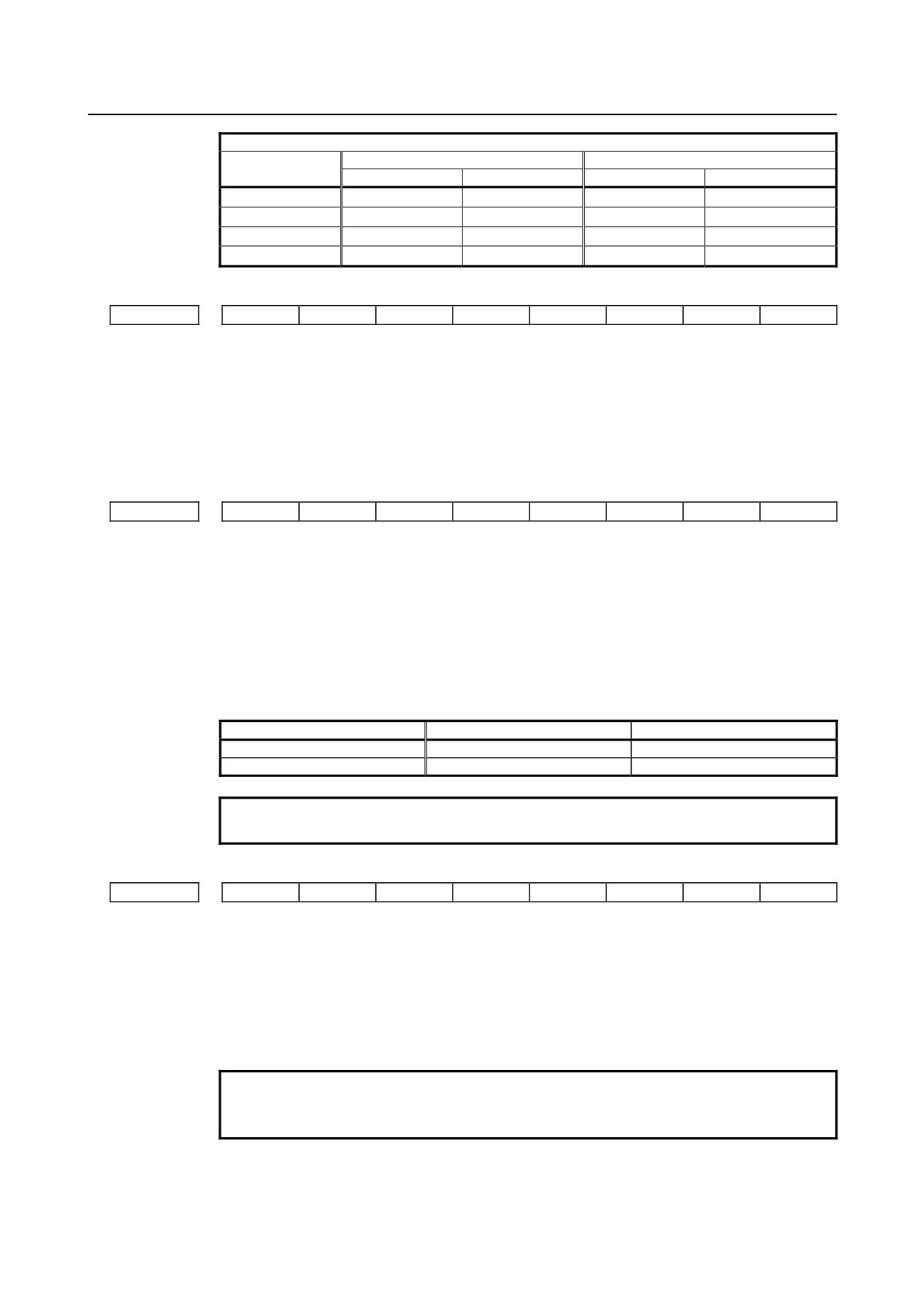
B-64310EN/02
4.DESCRIPTION OF PARAMETERS
D code
Compensation
Geometry
Wear
number
Variable number
Variable name
Variable number
Variable name
3
#2403
[#_OFSDG[3]]
#2603
[#_OFSDW[3]]
:
:
:
:
:
199
#2599
[#_OFSDG[199]]
#2799
[#_OFSDW[199]]
200
#2600
[#_OFSDG[200]]
#2800
[#_OFSDW[200]]
#7
#6
#5
#4
#3
#2
#1
#0
6005
SQC
[Input type] Parameter input
[Data type] Bit path
#0 SQC In the subprogram call function, a subprogram sequence number call is:
0: Not used.
1: Used.
#7
#6
#5
#4
#3
#2
#1
#0
6007
CVA
[Input type] Parameter input
[Data type] Bit path
#4 CVA The format for macro call arguments is specified as follows:
0: Arguments are passed in NC format without modifications.
1: Arguments are converted to macro format then passed.
Example)
When G65 P_ X10 ; is specified, the value in local variable #24 in the calling
program is set as follows:
Command
CVA=0
CVA=1
#24
0.01
0.01
ADP[#24]
10.0
0.01
NOTE
External operations are the same unless the ADP function is used.
#7
#6
#5
#4
#3
#2
#1
#0
6008
IJK
GMP
ADD
ISO
KOP
DSM
MCA
F0C
[Input type] Parameter input
[Data type] Bit path
#0 F0C The precision of operation is based on:
0: New specification.
1: FS0i-C compatible specification.
NOTE
For details, refer to the custom macro chapter in the OPERATOR’S
MANUAL (B-64304EN).
- 251 -
4.DESCRIPTION OF PARAMETERS
B-64310EN/02
#1 MCA A macro alarm specification based on system variable #3000 is selected as follows:
0: An alarm number obtained by adding 3000 to a value assigned to variable #3000 and
the corresponding message are displayed. (A value from 0 to 200 can be assigned to
variable #3000.)
1: A value assigned to variable #3000 and the corresponding message are displayed. (A
value from 0 to 4095 can be assigned to variable #3000.)
(Example)
Execution of #3000=1 (ALARM MESSAGE);
When bit 1 (MCA) of parameter No. 6008 is set to 0:
The alarm screen displays "MC 3001 ALARM MESSAGE".
When bit 1 (MCA) of parameter No. 6008 is set to 1:
The alarm screen displays "MC0001 ALARM MESSAGE".
#2 DSM On the custom macro screen, the rewriting of a system variable that can be specified
(written) on the left side from the MDI panel is:
0: Disabled.
1: Enabled.
#3 KOP When the NC is reset in the state where the line is made open by POPEN:
0: Communication continues, and the line is left open.
1: Communication stops, and the line is closed.
#4 ISO
0: When the EIA code is used, the bit patterns of codes specified instead of [, ], #, *,
=, ?, @, &, and _ are set in parameter No. 6010 to No. 6018.
1: When the ISO/ASCII code is used, the bit patters of codes specified instead of [, ], #,
*, =, ?, @, &, and _ are set in parameter No. 6010 to No. 6018.
#5 ADD When the number of digits in the integer part, a, in the format specification [a,b] of the
DPRNT statement is less than the number of digits in the integer part of an output
variable value:
0: The specified number of digits only are output, with the unspecified digits discarded.
1: An alarm for excessive digits is issued.
#6 GMP The calling of M, T, or a particular code during the calling of a G code, and the calling of
a G code during the calling of M, T, or particular code are:
0: Not allowed. (They are executed as an ordinary G, M, T, and NC address.)
1: Allowed.
#7 IJK For addresses I, J, and K specified as arguments:
0: Argument specification I or II is automatically determined.
1: Argument specification I is always used.
Example
When K_J_I_ is specified:
• When this parameter is set to 0:
Argument specification II is used and K=#6, J=#8, and I=#10
are specified.
• When this parameter is set to1:
Argument specification I is used and I=#4, J=#5, and K=#6 are
specified regardless of the specification order.
(Argument specification II cannot be used.)
- 252 -
B-64310EN/02
4.DESCRIPTION OF PARAMETERS
#7
#6
#5
#4
#3
#2
#1
#0
6010
*7
*6
*5
*4
*3
*2
*1
*0
#7
#6
#5
#4
#3
#2
#1
#0
6011
=7
=6
=5
=4
=3
=2
=1
=0
#7
#6
#5
#4
#3
#2
#1
#0
6012
#7
#6
#5
#4
#3
#2
#1
#0
#7
#6
#5
#4
#3
#2
#1
#0
6013
[7
[6
[5
[4
[3
[2
[1
[0
#7
#6
#5
#4
#3
#2
#1
#0
6014
]7
]6
]5
]4
]3
]2
]1
]0
#7
#6
#5
#4
#3
#2
#1
#0
6015
?7
?6
?5
?4
?3
?2
?1
?0
#7
#6
#5
#4
#3
#2
#1
#0
6016
@7
@6
@5
@4
@3
@2
@1
@0
#7
#6
#5
#4
#3
#2
#1
#0
6017
&7
&6
&5
&4
&3
&2
&1
&0
#7
#6
#5
#4
#3
#2
#1
#0
6018
_7
_6
_5
_4
_3
_2
_1
_0
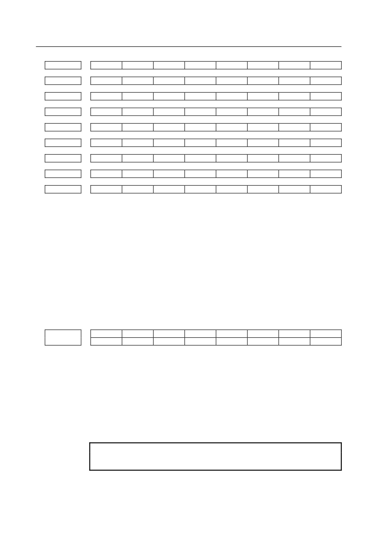
[Input type] Parameter input
[Data type] Bit path
*0 to *7 : The bit pattern of the EIA or ISO/ASCII code indicating * is set.
=0 to =7 : The bit pattern of the EIA or ISO/ASCII code indicating = is set.
#0 to #7 : The bit pattern of the EIA or ISO/ASCII code indicating # is set.
[0 to [7 : The bit pattern of the EIA or ISO/ASCII code indicating [ is set.
]0 to ]7 : The bit pattern of the EIA or ISO/ASCII code indicating ] is set.
?0 to ?7 : The bit pattern of the EIA or ISO/ASCII code indicating ? is set.
@0 to @7 : The bit pattern of the EIA or ISO/ASCII code indicating @ is set.
&0 to &7 : The bit pattern of the EIA or ISO/ASCII code indicating & is set.
_0 to _7 : The bit pattern of the EIA or ISO/ASCII code indicating _ is set.
0: A corresponding bit is 0.
1: A corresponding bit is 1.
#7
#6
#5
#4
#3
#2
#1
#0
DPD
MCO
6019
MCO
[Input type] Parameter input
[Data type] Bit
#0 MCO When data is output, the decimal number value of the macro variable data is
0: Not output as a comment.
1: Output at the same time as a comment.
After the number, data, and the variable name of the macro variable are output when data
output operation is performed the variable number and the value of the macro variable
data in decimal number are output as a comment.
NOTE
1 Output data by this parameter is "Comment", and this is ignored at
the time of reading.
- 253 -
4.DESCRIPTION OF PARAMETERS
B-64310EN/02
NOTE
2 Accuracy of the output data of the comment is up to 15 digits. The
range of output data are nine digits above decimal point and eight
digits below decimal point. "± OVER FLOW" is output instead of a
value when the total digits number is more than 16 and the digit
number above the decimal point is ten or more. When the number
of digits below the decimal point becomes nine digits or more, the
ninth place of the decimal point is rounded off and output.
Moreover, the seventh place or the eighth place of the decimal
point is rounded off and output when the total digits number is more
than 16 and the digit number above decimal point is nine or eight.
3 The output becomes "EMPTY" when displayed, the macro variable
data is "DATA EMPTY".
#2
DPD When no decimal point is specified for argument D of a macro call, the number of
decimal places is:
0:
0.
Example) If G65 P_ D1 is specified, #7 = 1.000 is passed as an argument.
1: Determined by the set unit of reference axis.
Example) When the reference axis is IS-B, if G65 P_ D1 is specified, #7 = 0.001 is
passed as an argument.
NOTE
When this parameter is set to 1, the operation equivalent to that of
the FS0i-TC is assumed.
6030
M code to execute external device subprogram calls
[Input type] Setting input
[Data type] 2-word path
[Valid data range] 0 to 99999999
Set the M code to execute external device subprogram calls. When 0 is set, M198 is used.
M01, M02, M30, M98, and M99 cannot be used to execute external device subprogram
calls. When a negative number, 1, 2, 30, 98, or 99 is set for this parameter, M198 is used
to execute external device subprogram calls.
6031
Start number of common variables to be protected among the common variables (#500 to #999)
6032
End number of common variables to be protected among the common variables (#500 to #999)
[Input type] Parameter input
[Data type] Word path
[Valid data range] 500 to 999
Among the common variables (#500 to #999), the range of common variables specified
by this parameter can be protected (by setting their attributes to read-only). If a write
attempt (on the left side) is made, an alarm is issued.
NOTE
Set 0 in both parameter No. 6031 and No. 6032 not to protect
common variables.
- 254 -
B-64310EN/02
4.DESCRIPTION OF PARAMETERS
6033
M code that validates a custom macro interrupt
6034
M code that invalidates a custom macro interrupt
[Input type] Parameter input
[Data type] 2-word path
[Valid data range] 3 to 99999999 (excluding 30, 98 and 99)
These parameters can be used when bit 4 (MPR) of parameter No.6003, is 1. M96 is used
as a valid M code and M97 is used as an invalid M code when MPR is 0, irrespective of
the state of this parameter.
Number of custom macro variables common to tool path (for #100 to #199)
6036
[Input type] Parameter input
[Data type] Word
[Valid data range] 0 to 100
When the memory common to paths is used, this parameter sets the number of custom
macro common variables to be shared (custom macro variables common to paths).
Common variables #100 to #199 may be shared. Ensure that the maximum number of
usable macro common variables is not exceeded.
Example
When 20 is set in parameter No. 6036
#100 to #119: Shared by all paths
#120 to #199: Used by each path independently
NOTE
When 0 or a negative value is set, the memory common to paths is
not used.
Number of custom macro variables common to tool path (for #500 to #999)
6037
[Input type] Parameter input
[Data type] Word
[Valid data range] 0 to 500
When the memory common to paths is used, this parameter sets the number of custom
macro common variables to be shared (custom macro variables common to paths).
Common variables #500 to #999 may be shared. Ensure that the maximum number of
usable macro common variables is not exceeded.
Example
When 50 is set in parameter No. 6037
#500 to #549: Shared by all paths
#550 to #999: Used by each path independently
NOTE
When 0 or a negative value is set, the memory common to paths is
not used.
- 255 -

4.DESCRIPTION OF PARAMETERS
B-64310EN/02
6038
Start G code used to call a custom macro
[Input type] Parameter input
[Data type] Word path
[Valid data range] -9999 to 9999
6039
Start program number of a custom macro called by G code
[Input type] Parameter input
[Data type] 2-word path
[Valid data range] 1 to 9999
6040
Number of G codes used to call custom macros
[Input type] Parameter input
[Data type] Word path
[Valid data range] 0 to 255
Set this parameter to define multiple custom macro calls using G codes at a time. With G
codes as many as the value set in parameter No. 6040 starting with the G code set in
parameter No. 6038, the custom macros of program numbers as many as the value set in
parameter No. 6040 starting with the program number set in parameter No. 6039 can be
called. Set 0 in parameter No. 6040 to disable this mode of calling.
If a negative value is set in parameter No. 6038, the modal call mode is entered.
[Example] When parameter No. 6038 = 900, parameter No. 6039 = 1000, and parameter No. 6040 =
100 are set, a set of 100 custom macro calls (simple calls) is defined as follows:
G900 → O1000
G901 → O1001
G902 → O1002
:
G999 → O1099
When the setting of parameter No. 6038 is changed to -900, the same set of custom macro
calls (modal calls) is defined.
NOTE
1 When the following conditions are satisfied, all calls using these
parameters are disabled:
1) When a value not within the specifiable range is set in each
parameter
2) (Value of parameter No.6039 + value of parameter No.6040 - 1)
> 9999
2 The specification of a mixture of simple calls and modal calls is not
allowed.
3 If a range of G codes set by these parameters duplicate G codes
specified in parameter No.6050 to No.6059, the calls specified by
parameter No.6050 to 6059 are made preferentially.
6044
Start M code used to call a subprogram
[Input type] Parameter input
[Data type] 2-word path
[Valid data range] 3 to 99999999
- 256 -

B-64310EN/02
4.DESCRIPTION OF PARAMETERS
6045
Start program number of a subprogram called by M code
[Input type] Parameter input
[Data type] 2-word path
[Valid data range] 1 to 9999
6046
Number of M codes used to call subprograms (number of subprograms called by M codes)
[Input type] Parameter input
[Data type] 2-word path
[Valid data range] 0 to 32767
Set this parameter to define multiple subprogram calls using M codes at a time. With M
codes as many as the value set in parameter No. 6046 starting with the M code set in
parameter No. 6044, the subprograms of program numbers as many as the value set in
parameter No. 6046 starting with the program number set in 6045 can be called. Set 0 in
parameter No. 6046 to disable this mode of calling.
[Example] When parameter No. 6044 = 80000000, parameter No. 6045 = 3000, and parameter No.
6046 = 100 are set, a set of 100 subprogram calls is defined as follows:
M80000000 → O3000
M80000001 → O3001
M80000002 → O3002
:
M80000099 → O3099
NOTE
1 When the following conditions are satisfied, all calls using these
parameters are disabled:
1) When a value not within the specifiable range is set in each
parameter
2) (Value of parameter No. 6045 + value of parameter No. 6046 -
1) > 9999
2 If a range of M codes set by these parameters duplicate M codes
specified in parameter No. 6071 to No. 6079, the calls specified by
parameter No. 6071 to 6079 are made preferentially.
6047
Start M code used to call a custom macro
[Input type] Parameter input
[Data type] 2-word path
[Valid data range] 3 to 99999999
6048
Start program number of a custom macro called by M code
[Input type] Parameter input
[Data type] 2-word path
[Valid data range] 1 to 9999
6049
Number of M codes used to call custom macros (number of custom macros called by M codes)
[Input type] Parameter input
[Data type] 2-word path
[Valid data range] 0 to 32767
- 257 -
4.DESCRIPTION OF PARAMETERS
B-64310EN/02
Set this parameter to define multiple custom macro calls using M codes at a time. With M
codes as many as the value set in parameter No. 6049 starting with the M code set in
parameter No. 6047, the custom macros of program numbers as many as the value set in
parameter No. 6049 starting with the program number set in parameter No. 6048 can be
called. Set 0 in parameter No. 6049 to disable this mode of calling.
[Example] When parameter No. 6047 = 90000000, parameter No. 6048 = 4000, and parameter No.
6049 = 100 are set, a set of 100 custom macro calls (simple calls) is defined as follows:
M90000000 → O4000
M90000001 → O4001
M90000002 → O4002
:
M90000099 → O4099
NOTE
1
When the following conditions are satisfied, all calls using these
parameters are disabled:
1) When a value not within the specifiable range is set in each
parameter
2) (Value of parameter No. 6048 + value of parameter No. 6049 -
1) > 9999
2
If a range of M codes set by these parameters duplicate M codes
specified in parameter No. 6080 through No. 6089, the calls
specified by parameter No. 6080 through 6089 are made
preferentially.
6050
G code that calls the custom macro of program number 9010
6051
G code that calls the custom macro of program number 9011
6052
G code that calls the custom macro of program number 9012
6053
G code that calls the custom macro of program number 9013
6054
G code that calls the custom macro of program number 9014
6055
G code that calls the custom macro of program number 9015
6056
G code that calls the custom macro of program number 9016
6057
G code that calls the custom macro of program number 9017
6058
G code that calls the custom macro of program number 9018
6059
G code that calls the custom macro of program number 9019
[Input type] Parameter input
[Data type] Word path
[Valid data range] (-9999 to 9999 : excluding 0, 5, 65, 66 and 67)
Set the G codes used to call the custom macros of program numbers 9010 to 9019.
However, note that when a negative value is set in this parameter, it becomes a modal call.
For example, if this parameter is set to -11, the modal call mode is entered by G11.
- 258 -
B-64310EN/02
4.DESCRIPTION OF PARAMETERS
6071
M code used to call the subprogram of program number 9001
6072
M code used to call the subprogram of program number 9002
6073
M code used to call the subprogram of program number 9003
6074
M code used to call the subprogram of program number 9004
6075
M code used to call the subprogram of program number 9005
6076
M code used to call the subprogram of program number 9006
6077
M code used to call the subprogram of program number 9007
6078
M code used to call the subprogram of program number 9008
6079
M code used to call the subprogram of program number 9009
[Input type] Parameter input
[Data type] 2-word path
[Valid data range] 3 to 99999999 (excluding 30, 98 and 99)
These parameters set the M codes that call the subprograms of program numbers 9001 to
9009.
NOTE
If the same M code is set in these parameters, the younger number
is called preferentially. For example, if 100 is set in parameter No.
6071 and 6072, and programs O9001 and O9002 both exist,
O9001 is called when M100 is specified.
6080
M code used to call the custom macro of program number 9020
6081
M code used to call the custom macro of program number 9021
6082
M code used to call the custom macro of program number 9022
6083
M code used to call the custom macro of program number 9023
6084
M code used to call the custom macro of program number 9024
6085
M code used to call the custom macro of program number 9025
6086
M code used to call the custom macro of program number 9026
6087
M code used to call the custom macro of program number 9027
6088
M code used to call the custom macro of program number 9028
6089
M code used to call the custom macro of program number 9029
[Input type] Parameter input
[Data type] 2-word path
[Valid data range] 3 to 99999999 (excluding 30, 98 and 99)
- 259 -
4.DESCRIPTION OF PARAMETERS
B-64310EN/02
Set the M codes used to call the custom macros of program numbers 9020 to 9029. The
simple call mode is set.
NOTE
1 If the same M code is set in these parameters, the younger number
is called preferentially. For example, if 200 is set in parameter No.
6081 and No. 6082, and programs O9021 and O9022 both exist,
O9021 is called when M200 is specified.
2 If the same M code is set in a parameter (No. 6071 to No. 6079)
used to call subprograms and in a parameter (No. 6080 to No.
6089) used to call custom macros, a custom macro is called
preferentially. For example, if 300 is set in parameter No. 6071 and
No. 6081, and programs O9001 and O9021 both exist, O9021 is
called when M300 is specified.
6090
ASCII code that calls the subprogram of program number 9004
6091
ASCII code that calls the subprogram of program number 9005
[Input type] Parameter input
[Data type] Byte path
[Valid data range] 65(A:41H) to 90(Z:5AH)
These parameters set the ASCII codes that call subprograms in decimal.
The settable addresses are indicated below.
Address
Parameter setting value
T series
M series
A
65
O
O
B
66
O
O
D
68
X
O
F
70
O
O
H
72
O
O
I
73
O
O
J
74
O
O
K
75
O
O
L
76
O
O
M
77
O
O
P
80
O
O
Q
81
O
O
R
82
O
O
S
83
O
O
T
84
O
O
V
86
X
O
X
88
X
O
Y
89
X
O
Z
90
X
O
NOTE
1 When address L is set, the number of repeats cannot be specified.
2 Set 0 when no subprogram is called.
6095
Number of programs used by the one-touch macro call function
[Input type] Parameter input
[Data type] Byte path
[Valid data range] 0 to 16
- 260 -

B-64310EN/02
4.DESCRIPTION OF PARAMETERS
This parameter registers the number of programs used by the one-touch macro call
function.
For example, when this parameter is set to 3, macro call start signals MCST1, MCST2,
and MCST3 are enabled.
When this parameter is set to 0, the one-touch macro call function is disabled.
6096
Number of the first program in the program group used by the one-touch macro call function
[Input type] Parameter input
[Data type] 2-word path
[Valid data range] 1 to 9999
This parameter registers the number of the first program in the program group used by the
one-touch macro call function.
For example, when this parameter is set to 9000, macro call start signals MCSTx and the
programs started by the signals are given below.
MCST1 signal:Starts O9000. (when parameter No.6095 is 1 or more)
MCST2 signal:Starts O9001. (when parameter No.6095 is 2 or more)
: : :
MCST15 signal: Starts O9014. (when parameter No.6095 is 15 or more)
MCST16 signal: Starts O9015. (when parameter No.6095 is 16 or more)
4.33 PARAMETERS OF PATTERN DATA INPUT
6101
Macro variable number selected first when pattern menu 1 is selected
6102
Macro variable number selected first when pattern menu 2 is selected
6103
Macro variable number selected first when pattern menu 3 is selected
6104
Macro variable number selected first when pattern menu 4 is selected
6105
Macro variable number selected first when pattern menu 5 is selected
6106
Macro variable number selected first when pattern menu 6 is selected
6107
Macro variable number selected first when pattern menu 7 is selected
6108
Macro variable number selected first when pattern menu 8 is selected
6109
Macro variable number selected first when pattern menu 9 is selected
6110
Macro variable number selected first when pattern menu 10 is selected
[Input type] Parameter input
[Data type] Word path
[Valid data range] 0,100 to 199,500 to 999
Set the macro variable number to be selected first when a pattern menu is selected on the
custom macro screen.
If 0 is specified, 500 is assumed.
If a value beyond the above range is entered, 100 is assumed.
- 261 -
4.DESCRIPTION OF PARAMETERS
B-64310EN/02
4.34 PARAMETERS OF SKIP FUNCTION
#7
#6
#5
#4
#3
#2
#1
#0
6200
SKF
SRE
SLS
HSS
SK0
GSK
[Input type] Parameter input
[Data type] Bit path
#0 GSK As a skip signal, the skip signal SKIPP is:
0: Invalid.
1: Valid.
#1 SK0 This parameter specifies whether the skip signal is made valid under the state of the skip
signal SKIP and the multistage skip signals SKIP2 to SKIP8.
0: Skip signal is valid when these signals are 1.
1: Skip signal is valid when these signals are 0.
#4 HSS
0: The skip function does not use high-speed skip signals while skip signals are input.
(The conventional skip signal is used.)
1: The step skip function uses high-speed skip signals while skip signals are input.
#5 SLS
0: The multi-step skip function does not use high-speed skip signals while skip signals
are input. (The conventional skip signal is used.)
1: The multi-step skip function uses high-speed skip signals while skip signals are
input.
NOTE
The skip signals (SKIP and SKIP2 to SKIP8) are valid regardless of
the setting of this parameter. They can also be disabled using bit 4
(IGX) of parameter No. 6201.
#6 SRE When a high-speed skip signal is used:
0: The signal is assumed to be input on the rising edge (contact open → close).
1: The signal is assumed to be input on the falling edge (contact close → open).
#7 SKF Dry run, override, and automatic acceleration/deceleration for G31 skip command
0: Disabled
1: Enabled
#7
#6
#5
#4
#3
#2
#1
#0
6201
SPE
IGX
TSE
SEB
[Input type] Parameter input
[Data type] Bit path
#1 SEB When a skip signal or measurement position arrival signal goes on while the skip function,
or the automatic tool length measurement (M series) or automatic tool compensation (T
series) is used, the accumulated pulses and positional deviation due to
acceleration/deceleration are:
0: Ignored.
1: Considered and compensated.
- 262 -