FANUC Series 0i-MODEL D, Series 0i Mate-MODEL D. PARAMETER MANUAL - page 7
B-64310EN/02
4.DESCRIPTION OF PARAMETERS
#0 NSAx When a move command is executed for an axis, the spindle speed arrival signal SAR is:
0: Checked.
1: Not checked.
Set an axis for which the spindle speed arrival signal SAR need not be checked when a
move command is executed for the axis. When a move command is specified only for an
axis with this parameter set to 1, the spindle speed arrival signal SAR is not checked.
#7
#6
#5
#4
#3
#2
#1
#0
3716
A/Ss
[Input type] Parameter input
[Data type] Bit spindle
NOTE
When this parameter is set, the power must be turned off before
operation is continued.
#0 A/Ss Spindle motor type is :
0: Analog spindle.
1: Serial spindle.
NOTE
1 To use a serial spindle, set bit 5 (SSN) of parameter No. 8133 to 0.
2 A maximum of one analog spindle can be controlled.
3 When using an analog spindle, set it at the end of the spindle
configuration.
3717
Motor number to each spindle
NOTE
When this parameter is set, the power must be turned off before
operation is continued.
[Input type] Parameter input
[Data type] Byte spindle
[Valid data range] 0 to Maximum number of controlled axes
Set a spindle amplifier number to be assigned to each spindle.
0: No spindle amplifier is connected.
1: Spindle motor connected to amplifier number 1 is used.
2: Spindle motor connected to amplifier number 2 is used.
3: Spindle motor connected to amplifier number 3 is used.
NOTE
When using an analog spindle, set it at the end of the spindle
configuration.
(Example)
When there are three spindles in an entire system (two serial
spindles and one analog spindle), set the spindle amplifier number
(this parameter) of the analog spindle to 3.
- 173 -
4.DESCRIPTION OF PARAMETERS
B-64310EN/02
3718
Subscript for display of a serial spindle or analog spindle
[Input type] Parameter input
[Data type] Byte spindle
[Valid data range] 0 to 122
Set a subscript to be added to spindle speed display on a screen such as the position
display screen.
3720
Number of position coder pulses
NOTE
When this parameter is set, the power must be turned off before
operation is continued.
[Input type] Parameter input
[Data type] 2-word spindle
[Unit of data] Detection unit
[Valid data range] 1 to 32767
Set the number of position coder pulses.
3721
Number of gear teeth on the position coder side
[Input type] Parameter input
[Data type] Word spindle
[Valid data range] 0 to 9999
Set the number of gear teeth on the position coder side in speed control (such as feed per
revolution and threading).
3722
Number of gear teeth on the spindle side
[Input type] Parameter input
[Data type] Word spindle
[Valid data range] 0 to 9999
Set the number of gear teeth on the spindle side in speed control (such as feed per
revolution and threading).
#7
#6
#5
#4
#3
#2
#1
#0
3729
CSCs
NCSs
CSNs
FPRs
ORTs
[Input type] Parameter input
[Data type] Bit spindle
#0 ORTs When a serial spindle is used, the spindle orientation function of stop position external
setting type based on the position coder is:
0: Not performed.
1: Performed.
#1 FPR Feed per revolution (without a position coder) is:
0: Not used for a spindle.
1: Used for a spindle.
In a machine that does not use a position coder, when bit 1 (FPR) of parameter No. 3729
is set to 1 for each axis, feed per revolution can be performed with a spindle command. A
feed per revolution is specified with G95 (G99 for T series) in the same way as for
normal operation.
- 174 -
B-64310EN/02
4.DESCRIPTION OF PARAMETERS
When multispindle control is performed, the target spindle for feed per revolution is
selected with a position coder select signal (PC2SLC<Gn028.7>).
NOTE
Enable constant surface speed control (bit 0 (SSC) of parameter
No. 8133 is 1).
#2
CSNs When the Cs contour control mode is turned off, an in-position check is:
0: Performed.
1: Not performed.
NOTE
If this parameter is set to 1, the same operation as in FS0i-C is
assumed.
#3
NCSs When the Cs contour control mode is set:
0: Switching to Cs contour control is completed when the spindle activating current is
on (the spindle amplifier is ready for operation in the Cs contour control mode).
1: Switching to Cs contour control is completed even when the spindle activating
current is off (the spindle amplifier is not ready for operation in the Cs contour
control mode).
If this parameter is set to 1, the Cs contour control switch end signal is output without
waiting for the spindle to decelerate to a stop.
#7
CSCs The increment system of the Cs contour control axis is:
0: IS-B.
1: IS-C.
3730
Data used for adjusting the gain of the analog output of spindle speed
[Input type] Parameter input
[Data type] Word spindle
[Unit of data] 0.1%
[Valid data range] 700 to 1250
Set data used for adjusting the gain of the analog output of spindle speed.
[Adjustment method]
<1> Assign standard value 1000 to the parameter.
<2> Specify the spindle speed so that the analog output of the spindle speed is the
maximum voltage (10 V).
<3> Measure the output voltage.
<4> Assign the value obtained by the following equation to parameter No.3730.
Setting value = (10 (V) / Measured data (V)) × 1000
<5> After setting the parameter, specify the spindle speed so that the analog output of the
spindle speed is the maximum voltage. Confirm that the output voltage is 10V.
NOTE
This parameter needs not to be set for serial spindles.
3731
Compensation value for the offset voltage of spindle speed analog output
[Input type] Parameter input
[Data type] Word spindle
- 175 -
4.DESCRIPTION OF PARAMETERS
B-64310EN/02
[Unit of data] Velo
[Valid data range] -1024 to 1024
Set a compensation value for the offset voltage of spindle speed analog output.
Setting = -8191 × offset voltage (V)/12.5
[Adjustment method]
<1> Assign standard value 0 to the parameter.
<2> Specify the spindle speed so that the analog output of the spindle speed is 0.
<3> Measure the output voltage.
<4> Assign the value obtained by the following equation to parameter No.3731.
Setting value = (-8191 × Offset voltage (V)) / 12.5
<5> After setting the parameter, specify the spindle speed so that the analog output of the
spindle speed is 0. Confirm that the output voltage is 0V.
NOTE
This parameter needs not to be set for serial spindles.
3732
The spindle speed during spindle orientation or the spindle motor speed during spindle gear shift
[Input type] Parameter input
[Data type] 2-word path
[Valid data range] 0 to 20000
Set the spindle speed during spindle orientation or the spindle motor speed during gear
shift.
When bit 1 (GST) of parameter No.3705 is set to 0, set the spindle speed during spindle
orientation in min-1.
When bit 1 (GST) of parameter No.3705 is set to 1, set the spindle motor speed during
spindle gear shift calculated from the following formula.
For a serial spindle
Setting value =
(Spindle motor speed during spindle gear shift / Maximum spindle motor speed) × 16383
For an analog spindle
Setting value =
(Spindle motor speed during spindle gear shift / Maximum spindle motor speed) × 4095
3735
Minimum clamp speed of the spindle motor
[Input type] Parameter input
[Data type] Word path
[Valid data range] 0 to 4095
Set the minimum clamp speed of the spindle motor.
Setting value =
(Minimum clamp speed of the spindle motor / Maximum spindle motor speed) × 4095
3736
Maximum clamp speed of the spindle motor
[Input type] Parameter input
[Data type] Word path
[Valid data range] 0 to 4095
- 176 -
B-64310EN/02
4.DESCRIPTION OF PARAMETERS
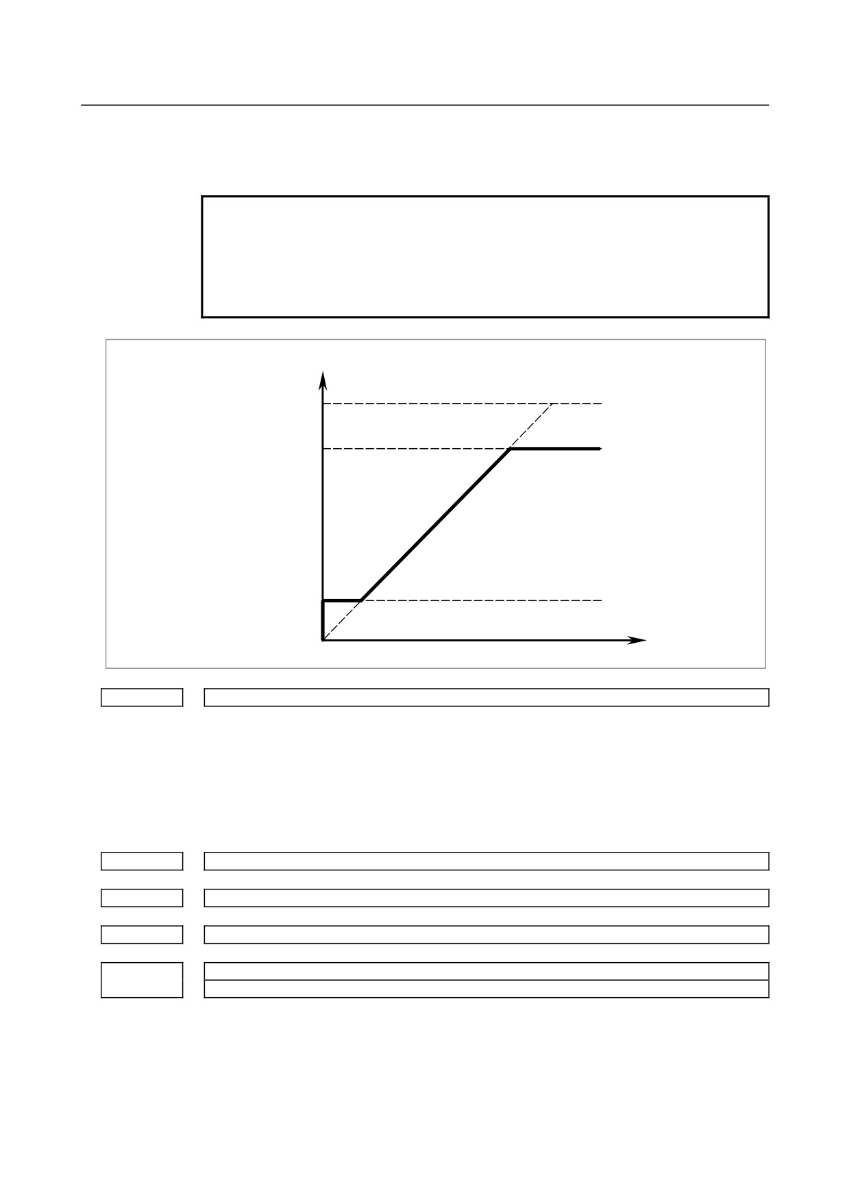
Set the maximum clamp speed of the spindle motor.
Setting value =
(Maximum clamp speed of the spindle motor / Maximum spindle motor speed) × 4095
NOTE
When constant surface speed control (bit 0 (SSC) of parameter No.
8133 is 1) or bit 4 of parameter No. 3706 is set, this parameter is
invalid. In this case, the maximum clamp speed of the spindle
motor can be set, but the maximum spindle motor speed can be set
by parameter No. 3772.
Spindle motor speed
Max. speed (4095, 10V)
Spindle motor max. clamp speed
(Parameter No.3736)
Spindle motor minimum clamp speed
(Parameter No.3735)
Spindle speed
(S command)
3740
Time elapsed prior to checking the spindle speed arrival signal
[Input type] Parameter input
[Data type] Word path
[Unit of data] msec
[Valid data range] 0 to 32767
Set the time elapsed from the execution of the S function up to the checking of the
spindle speed arrival signal.
3741
Maximum spindle speed for gear 1
3742
Maximum spindle speed for gear 2
3743
Maximum spindle speed for gear 3
Maximum spindle speed for gear 4
3744
(Note)
[Input type] Parameter input
[Data type] 2-word spindle
[Unit of data] min-1
[Valid data range] 0 to 99999999
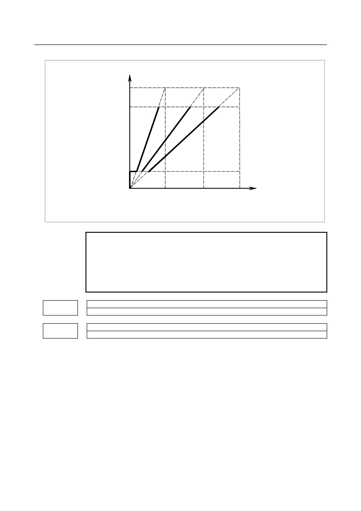
Set the maximum spindle speed corresponding to each gear.
- 177 -
4.DESCRIPTION OF PARAMETERS
B-64310EN/02
Spindle motor speed
Max. speed (4095, 10V)
Spindle motor max. clamp speed
(Parameter No.3736)
Spindle motor minimum clamp speed
(Parameter No.3735)
Spindle speed command
(S command)
Gear 1
Gear 2
Gear 3
Max. speed
Max. speed
Max. speed
(Parameter
(Parameter
(Parameter
No.3741)
No.3742)
No.3743)
NOTE
If a type-T gear shift scheme is selected for the M series (with the
constant surface speed control option installed or bit 4 (GTT) of
parameter No. 3706 = 1), parameter No. 3744 is usable also in the
M series.
Note, however, that, even in this case, only up to three main gear
stages are usable for rigid tapping.
3751
Spindle motor speed when switching from gear 1 to gear 2
3752
Spindle motor speed when switching from gear 2 to gear 3
[Input type] Parameter input
[Data type] Word path
[Valid data range] 0 to 4095
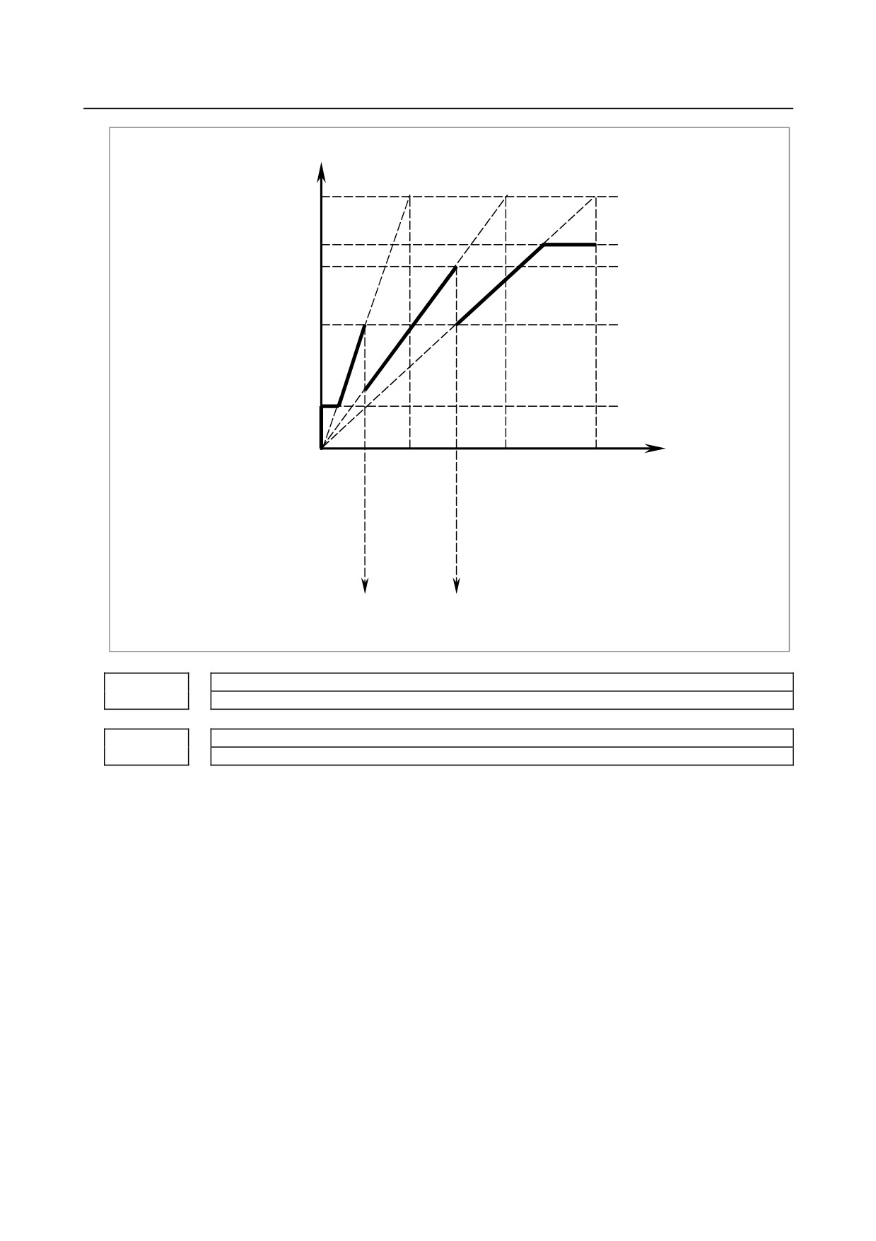
For gear switching method B, set the spindle motor speed when the gears are switched.
Setting value =
(Spindle motor speed when the gears are switched / Maximum spindle motor speed) ×
4095
- 178 -
B-64310EN/02
4.DESCRIPTION OF PARAMETERS
Spindle motor speed
Max. speed (4095, 10V)
Spindle motor max. clamp speed
Parameter No.3736
Speed at gear 2-3 change point
Parameter No.3752
Speed at gear 1-2 change point
Parameter No.3751
Spindle motor minimum clamp speed
Parameter No.3735
Spindle speed
command
Gear 1
Gear 2
Gear 3
(S command)
max. speed
max. speed
max speed
parameter
parameter
parameter
No.3741
No.3742
No.3743
Gear 1-2
Gear 2-3
change
change
point
point
3761
Spindle speed when switching from gear 1 to gear 2 during tapping
3762
Spindle speed when switching from gear 2 to gear 3 during tapping
[Input type] Parameter input
[Data type] 2-word path
[Unit of data] min-1
[Valid data range] 0 to 99999999
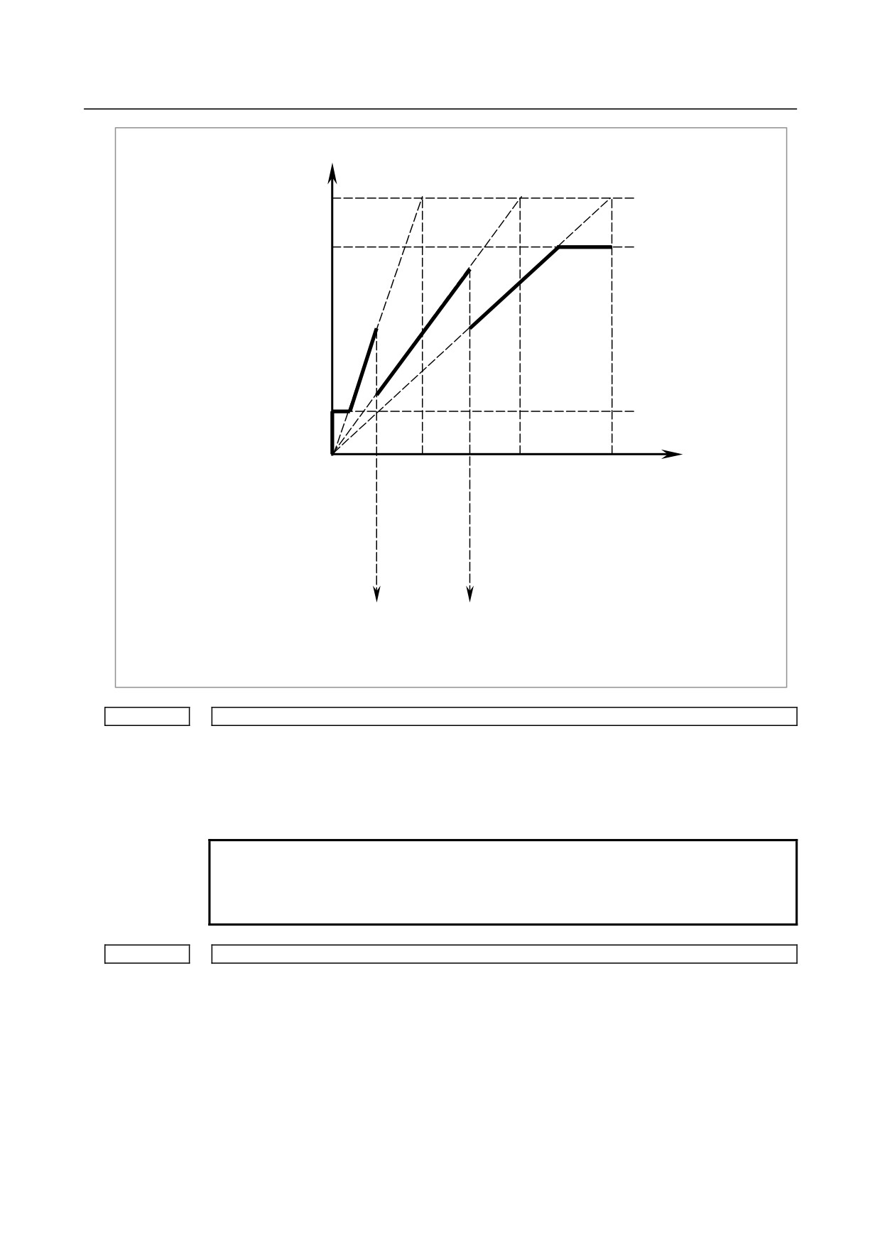
When method B is selected as the gear change method in the tapping cycle (when bit 3
(SGT) of parameter No. 3705 is set to 1), set the spindle speed at a change point of each
gear.
- 179 -
4.DESCRIPTION OF PARAMETERS
B-64310EN/02
Spindle motor speed
Max. speed (4095, 10V)
Spindle motor max. clamp speed
(Parameter No.3736)
Spindle motor minimum clamp speed
(Parameter No.3735)
Spindle speed
command
Gear 1
Gear 2
Gear 3
(S command)
Max. speed
Max. speed
Max. speed
Parameter
Parameter
Parameter
No.3741
No.3742
No.3743
Gear 1-2
Gear 2-3
change point
change point
parameter
parameter
No.3761
No.3762
3770
Axis as the calculation reference in constant surface speed control
[Input type] Parameter input
[Data type] Byte path
[Valid data range] 0 to Number of controlled axes
Set the axis as the calculation reference in constant surface speed control.
NOTE
When 0 is set, constant surface speed control is always applied to
the X-axis. In this case, specifying P in a G96 block has no effect
on the constant surface speed control.
3771
Minimum spindle speed in constant surface speed control mode (G96)
[Input type] Parameter input
[Data type] 2-word path
[Unit of data] min-1
[Valid data range] 0 to 32767
Set the minimum spindle speed in the constant surface speed control mode (G96).
The spindle speed in constant surface speed control is clamped to the speed given by
parameter 3771.
- 180 -
B-64310EN/02
4.DESCRIPTION OF PARAMETERS
3772
Maximum spindle speed
[Input type] Parameter input
[Data type] 2-word spindle
[Unit of data] min-1
[Valid data range] 0 to 99999999
This parameter sets the maximum spindle speed.
When a command specifying a speed exceeding the maximum speed of the spindle is
specified , or the speed of the spindle exceeds the maximum speed because of the spindle
speed override function, the spindle speed is clamped at the maximum speed set in the
parameter.
CAUTION
1 When 0 is set in this parameter, the speed of the spindle is not
clamped.
2 When spindle speed command control is applied using the PMC,
this parameter has no effect, and the spindle speed is not clamped.
NOTE
1 For the M series, this parameter is valid when constant surface
speed control is selected (bit 0 (SSC) of parameter No. 8133 is 1).
2 When the constant surface speed control is selected, the spindle
speed is clamped at the maximum speed, regardless of whether
the G96 mode or G97 mode is specified.
3775
Default P command value for spindle selection in multi-spindle control
NOTE
When this parameter is set, the power must be turned off before
operation is continued.
[Input type] Parameter input
[Data type] Word path
[Valid data range] 0 to 32767
When bit 3 (MPP) of parameter No. 3703 is set to 1 and bit 2 (MPA) of parameter No.
3706 is set to 1 in multi-spindle control, set a default P command value applicable if S_P_
is not specified even once after power-up.
3781
P code for selecting the spindle in multi-spindle control
[Input type] Parameter input
[Data type] Word spindle
[Valid data range] 0 to 32767
If bit 3 (MPP) of parameter No. 3703 is set to 1, set the P code to select each spindle
under multi-spindle control. Specify the P code in a block containing the S command.
[Example] If the P code value for selecting the second spindle is set to 3,
S1000 P3;
causes the second spindle to rotate at S1000.
- 181 -
4.DESCRIPTION OF PARAMETERS
B-64310EN/02
NOTE
1 This parameter is valid if bit 3 (MPP) of parameter No. 3703 is set
to 1.
2 If this parameter is set to 0, the corresponding spindle cannot be
selected by a P code.
3 Under 2-path control, the P code specified here is valid for each
path.
For instance, if the P code to select the first spindle of path 2 is set
to 21, specifying S1000 P21; in path 1 causes the first spindle of
path 2 to be rotated at S1000.
4 Identical P code values cannot be used for different spindles.
(Identical P code values cannot be used even if the paths are
different.)
5 When this parameter is used (when bit 3 (MPP) of parameter No.
3703 is set to 1), the spindle command selection signal is invalid.
6 To use this parameter, enable multi-spindle control (bit 3 (MSP) of
parameter No. 8133 is 1).
#7
#6
#5
#4
#3
#2
#1
#0
3798
ALM
[Input type] Parameter input
[Data type] Bit
#0 ALM The spindle alarm (SP****) for all spindles is:
0: Enabled.
1: Ignored.
When this parameter is set to 1, the spindle-related alarms are ignored. So, be sure to set
this parameter to 0 at all times except for special cases such as maintenance.
#7
#6
#5
#4
#3
#2
#1
#0
3799
SSHs
SVPs
ASDs
NDPs
NALs
[Input type] Parameter input
[Data type] Bit spindle
#0 NALs An alarm detected on the spindle amplifier side is:
0: Displayed.
1: Not displayed.
(This parameter is valid when bit 0 (ALM) of parameter No. 3798 is set to 0.)
When this parameter is set to 1, an alarm detected on the spindle amplifier side is ignored.
So, be sure to set this parameter to 0 at all times except for special cases such as
maintenance.
#1 NDPs When an analog spindle is used, a position coder disconnection check is:
0: Made.
1: Not made.
(This parameter is valid when bit 0 (NAL) of parameter No. 3799 is set to 0.)
When no position coder is used with an analog spindle, set this parameter to 1.
#2 ASDs When a serial spindle is used, a spindle speed is calculated based on:
0: Feedback pulses from the position coder.
1: Speed monitor.
- 182 -

B-64310EN/02
4.DESCRIPTION OF PARAMETERS
#3 SVPs As synchronization errors displayed on the spindle screen:
0: Monitor values are displayed.
1: Peak-hold values are displayed,
Spindle synchronization errors are displayed on the side of the spindle that functions as a
slave axis in spindle synchronization control.
#5 SSHs Displaying of total spindle speed data on the diagnosis screen is:
0: Disabled.
1: Enabled.
Parameters for Control of Serial Interface Spindle Cs Contouring Control Axis
Number
Data format
Description
Number of the servo axis whose loop gain is to be changed according to the
3900
Byte path
set values of parameters 3901 to 3904 when the Cs contouring axis is
controlled
3901
Word path
Loop gain for the servo axis when the Cs contouring axis is controlled for
spindle gear 1 selection
3902
Word path
First group
Loop gain for the servo axis when the Cs contouring axis is controlled for
spindle gear 2 selection
3903
Word path
Loop gain for the servo axis when the Cs contouring axis is controlled for
spindle gear 3 selection
3904
Word path
Loop gain for the servo axis when the Cs contouring axis is controlled for
spindle gear 4 selection
Number of the servo axis whose loop gain is to be changed according to the
3910
Byte path
set values of parameters 3911 to 3914 when the Cs contouring axis is
controlled
3911
Word path
Loop gain for the servo axis when the Cs contouring axis is controlled for
spindle gear 1 selection
3912
Word path
Second
Loop gain for the servo axis when the Cs contouring axis is controlled for
group
spindle gear 2 selection
3913
Word path
Loop gain for the servo axis when the Cs contouring axis is controlled for
spindle gear 3 selection
3914
Word path
Loop gain for the servo axis when the Cs contouring axis is controlled for
spindle gear 4 selection
Number of the servo axis whose loop gain is to be changed according to the
3920
Byte path
set values of parameters 3921 to 3924 when the Cs contouring axis is
controlled
3921
Word path
Loop gain for the servo axis when the Cs contouring axis is controlled for
spindle gear 1 selection
3922
Word path
Third group
Loop gain for the servo axis when the Cs contouring axis is controlled for
spindle gear 2 selection
3923
Word path
Loop gain for the servo axis when the Cs contouring axis is controlled for
spindle gear 3 selection
3924
Word path
Loop gain for the servo axis when the Cs contouring axis is controlled for
spindle gear 4 selection
Number of the servo axis whose loop gain is to be changed according to the
3930
Byte path
set values of parameters 3931 to 3934 when the Cs contouring axis is
controlled
3931
Word path
Loop gain for the servo axis when the Cs contouring axis is controlled for
spindle gear 1 selection
3932
Word path
Fourth group
Loop gain for the servo axis when the Cs contouring axis is controlled for
spindle gear 2 selection
3933
Word path
Loop gain for the servo axis when the Cs contouring axis is controlled for
spindle gear 3 selection
3934
Word path
Loop gain for the servo axis when the Cs contouring axis is controlled for
spindle gear 4 selection
- 183 -

4.DESCRIPTION OF PARAMETERS
B-64310EN/02
<Setting method>
First, select servo axes which perform interpolation with the Cs contouring axis. (Up to
four axes can be selected.)
When there is no servo axis for interpolation with the Cs contouring axis, set the
parameters 3900, 3910, 3920, and 3930 to 0 to terminate parameter setting.
When there are servo axes for interpolation with the Cs contouring axis, the parameters
must be set according to the procedure below for each axis.
(1) Set the number of a servo axis (1 to maximum number of controlled axes) for
interpolation with the Cs contouring axis in parameters 39n0 (n = 0, 1, 2, and 3).
(2) Set loop gain values of the servo axis specified in (1) above which is used when the
Cs contouring axis is controlled in parameters 39n1, 39n2, 39n3, and 39n4. (There
are four stages for main gears used.)
(3) When the number of specified servo axes is less than 4, set the remaining parameters
(39n0) to 0 to terminate parameter setting.
When the number of a Cs contouring axis is set to parameter 39n0, the parameter is
assumed to be set to 0.
NOTE
1 In general, it is difficult to set a high loop gain for a spindle motor
axis when compared with a servo axis. These parameters are
provided so that, by changing the loop gain of a servo axis that
requires interpolation with the Cs contour axis, interpolation control
can be exercised correctly between the Cs axis and servo axis
while the spindle exercises Cs contour control.
2 The loop gain of the servo axis is changed using the parameter
settings made for a spindle gear selected at the time of conversion
from the spindle mode to the Cs contour control mode.
In normal use, it is unlikely that the gear of the spindle is switched
during Cs contour control. However, note that if the gear of the
spindle is changed during Cs contour control, the loop gain of the
servo axis is not changed.
3 Even when multiple Cs axes are used with one path (bit 7 (CSS) of
parameter No. 3704 = 1), these parameters are shared.
Parameters for Serial interface spindle or spindle
Parameters Nos. 4000 to 4799 below are basically used with the serial spindle amplifier.
For details of these parameters, refer to either of the following manuals and other related
documents, depending on the spindle that is actually connected.
• FANUC AC SPINDLE MOTOR αi series Parameter Manual (B-65280EN)
#7
#6
#5
#4
#3
#2
#1
#0
4000
to
to
4015
(No user setting allowed = Note 1)
to
to
4019
(Note 2)
[Input type] Parameter input
[Data type] Bit spindle
- 184 -
B-64310EN/02
4.DESCRIPTION OF PARAMETERS
4020
to
to
4133
[Input type] Parameter input
[Data type] Word spindle
4134
4135
[Input type] Parameter input
[Data type] 2-word spindle
4136
to
to
4175
[Input type] Parameter input
[Data type] Word spindle
#7
#6
#5
#4
#3
#2
#1
#0
4352
4353
[Input type] Parameter input
[Data type] Bit spindle
4354
to
to
4371
(No user setting allowed = Note 1)
4372
[Input type] Parameter input
[Data type] Word spindle
#7
#6
#5
#4
#3
#2
#1
#0
4373
4374
[Input type] Parameter input
[Data type] Bit spindle
4375
to
to
4393
[Input type] Parameter input
[Data type] Word spindle
#7
#6
#5
#4
#3
#2
#1
#0
4394
to
to
4403
[Input type] Parameter input
[Data type] Bit spindle
- 185 -
4.DESCRIPTION OF PARAMETERS
B-64310EN/02
4404
to
to
4466
[Input type] Parameter input
[Data type] Word spindle
#7
#6
#5
#4
#3
#2
#1
#0
4467
to
to
4476
[Input type] Parameter input
[Data type] Bit spindle
4477
to
to
4539
[Input type] Parameter input
[Data type] Word spindle
#7
#6
#5
#4
#3
#2
#1
#0
4540
to
to
4549
[Input type] Parameter input
[Data type] Bit spindle
4550
to
to
4669
[Input type] Parameter input
[Data type] Word spindle
#7
#6
#5
#4
#3
#2
#1
#0
4670
to
to
4679
[Input type] Parameter input
[Data type] Bit spindle
4680
to
to
4799
[Input type] Parameter input
[Data type] Word spindle
NOTE
1 Among the parameters of the spindle amplifier with the serial
interface, parameters No. 4015 cannot be changed by the users.
These parameters require to assign optional software to the CNC
and are automatically set depending on the type of the software.
The setting of parameter No. 4371 is also unchangeable by the
user.
- 186 -

B-64310EN/02
4.DESCRIPTION OF PARAMETERS
NOTE
2
To set the parameters of the spindle amplifier with the serial
interface automatically, set #7 of parameter No.4019 to 1, assign
the model code of the motor to be used to parameter No.4133, turn
off the power of the CNC and spindle amplifier, and restart the
CNC and spindle amplifier.
3
Parameters No.4000 to No.4799 are used in the processing on the
spindle amplifier. For details of these parameters, refer to either of
the following manuals, depending on the serial spindle that is
actually used.
- FANUC AC SPINDLE MOTOR αi series Parameter Manual
(B-65280EN)
4
The CNC can control up to three spindle amplifiers with the serial
interface.
5
The CNC stores the parameters of the spindle amplifier with the
serial interface. The CNC sends them to the spindle amplifier at the
system power on and they are used in the unit.
These parameters are sent from the CNC to the spindle amplifier in
a batch when:
-
The CNC is switched on.
If these parameters are rewritten, they are sent from the CNC to
the spindle amplifier sequentially when:
-
The parameters have been entered from the MDI.
-
The parameters have been entered as programmable (G10).
-
The parameters have been entered via the reader/punch
interface.
To set parameters automatically, upload parameters corresponding
to the motor model from the spindle amplifier to the CNC prior to
the procedure specified above.
The parameters of the spindle amplifier with serial interface can be
changed after the system starts. Changing the parameters
(No.4000 to No.4799 "S1" to "S8") in the CNC sends them to the
spindle amplifier at an appropriate time and the parameters in the
unit are updated.
(Be careful not to change parameters incorrectly.)
#7
#6
#5
#4
#3
#2
#1
#0
SCB
SYM
4800
EPZ
SCB
SYM
[Input type] Parameter input
[Data type] Bit
NOTE
When at least one of these parameters is set, the power must be
turned off before operation is continued.
#4 SYM As the maximum spindle speed in spindle synchronization control:
0: The maximum spindle speed of the master spindle is used.
1: The maximum spindle speed of the master spindle or slave spindle, whichever lower,
is used.
- 187 -

4.DESCRIPTION OF PARAMETERS
B-64310EN/02
#5
SCB The combination of a master spindle and slave spindle for spindle synchronization
depends on:
0: Setting of bit 4 (SSS) of parameter No. 3704.
When bit 4 (SSS) of parameter No. 3704 is set to 0
The first spindle and second spindle of each path can be selected as the master
spindle and slave spindle, respectively, for spindle synchronization.
When bit 4 (SSS) of parameter No. 3704 is set to 1
A combination of arbitrary spindles of each path can be selected for spindle
synchronization.
Set a master spindle for each slave spindle in parameter No. 4831. Set a spindle
number of each path.
By setting a spindle number common to the system in parameter No. 4832, an
arbitrary spindle that belongs to a different path can be selected as a master spindle
for spindle synchronization. Set a spindle number common to the system. Set
parameter No. 4831 to 0. Spindle synchronization based on arbitrary spindles must
be enabled for the path to which a slave spindle belongs and for the path to which a
master spindle belongs.
1:
0i-TTC system compatible specifications.
The first spindle of path 1 and the first spindle of path 2 can be selected as the
master spindle and slave spindle, respectively, for spindle synchronization.
As control signals, the signal interface of the
0i-TTC system compatible
specifications can be used.
#6
EPZ When the parking signal is switched in the reference position established state during Cs
contour control exercised using simple spindle synchronous control (M series):
0: Reference position established state is continued.
1: Reference position established state is canceled.
If this parameter is set, the same reference position return operation as manual reference
position return is performed with the G28 command immediately after the parking signal
is switched.
The G00 command performs a positioning operation including reference position return
(when bit 1 (NRF) of parameter No. 3700 is set to 0).
#7
#6
#5
#4
#3
#2
#1
#0
4801
SNDs
[Input type] Parameter input
[Data type] Bit spindle
NOTE
When this parameter is set, the power must be turned off before
operation is continued.
#0 SNDs During spindle synchronization control, the rotation direction of each spindle motor is:
0: Same as the specified sign.
1: Opposite to the specified sign.
Error pulse between two spindles when synchronizing phases in the spindle synchronization control
4810
mode
[Input type] Parameter input
[Data type] Word spindle
[Unit of data] Detection unit
- 188 -
B-64310EN/02
4.DESCRIPTION OF PARAMETERS
[Valid data range] 0 to 255
Set an allowable error pulse value between two spindles at phase synchronization time in
the spindle synchronization control mode.
This parameter is used to check the completion of phase synchronization performed in the
spindle synchronization control mode and to check the phase difference during spindle
synchronization control.
When the error pulse value between two spindles become equal to or less than the value
set in this parameter, the spindle phase synchronization control completion signals
FSPPH<F044.3> and FSPPH1, 2<F289.0, 1> are set to 1.
Allowable error count for the error pulses between two spindles in the spindle synchronization control
4811
mode
[Input type] Parameter input
[Data type] Word spindle
[Unit of data] Detection unit
[Valid data range] 0 to 32767
Set the allowable error count for the error pulses between two spindles in the spindle
synchronization control mode.
This parameter is used to check a spindle synchronization error phase difference.
When a spindle synchronization error equal to or greater than the value set in this
parameter is detected, the phase error monitor signals SYCAL<F044.4> and SYCAL1,
2<F043.0, 1> are set to 1.
4821
Master axis of each slave spindle under simple synchronous spindle control
NOTE
When this parameter is set, the power must be turned off before
operation is continued.
[Input type] Parameter input
[Data type] Byte spindle
[Valid data range] 0 to Maximum number of controlled spindle axes
When a spindle is set as a slave spindle in simple spindle synchronous control (M series)
on each spindle, set which spindle (master spindle) the slave spindle is to be synchronized
with.
Examples of parameter setting)
• If the master spindle is the first spindle and the slave spindle is the second spindle:
No.4821(1)=0
No.4821(2)=1
NOTE
1 This parameter is valid if bit 5 (SSY) of parameter No. 3704 is set
to 1.
2 Be sure to set 0 for a spindle that is to function as a master spindle.
4826
Allowable error count for the error pulses between two spindles in the simple synchronization spindle
control mode
[Input type] Parameter input
[Data type] Word spindle
- 189 -
4.DESCRIPTION OF PARAMETERS
B-64310EN/02
[Unit of data] Detection unit
[Valid data range] 0 to 32767
Set the allowable error count for the error pulses between two spindles in the simple
synchronization spindle control (M series) mode.
This parameter is used to check a spindle synchronization error phase difference.
When a spindle synchronization error equal to or greater than the value set in this
parameter is detected, the spindle phase error monitor signals SYCAL<Fn044.4> and
SYCALs are set to 1.
NOTE
1 The detection unit per pulse depends on the spindle control mode
(Cs contour control or rigid tapping).
2 Set this parameter for a spindle that is to function as a slave
spindle. Set 0 for the master spindle.
3 In the spindle rotation control mode, synchronization error detection
is not performed.
4831
Master axis of each slave spindle under spindle synchronous control
NOTE
When this parameter is set, the power must be turned off before
operation is continued.
[Input type] Parameter input
[Data type] Byte spindle
[Valid data range] 0 to Maximum number of controlled spindle axes (within a path)
When a spindle is set as a slave spindle in spindle synchronization control on each
spindle, set which spindle (master spindle) the slave spindle is to be synchronized with.
Examples of parameter setting)
• When spindle synchronization control is exercised with the first spindle selected as a
master spindle and the second spindle selected as a slave spindle
No.4831(1)=0
No.4831(2)=1
NOTE
1 This parameter is valid if bit 4 (SSS) of parameter No. 3704 is set
to 1.
2 The setting of a slave spindle as a master spindle is invalid. Be
sure to set 0 for a spindle that is to function as a master spindle.
3 In this parameter, set a spindle number within the same path.
When a spindle not belonging to the local path is to be selected as
a master spindle for spindle synchronization, set a spindle number
common to the system in parameter No. 4832. In such a case, set
0 in this parameter.
Master spindle of each slave spindle under spindle synchronization control (spindle number common
4832
to the system)
NOTE
When this parameter is set, the power must be turned off before
operation is continued.
- 190 -
B-64310EN/02
4.DESCRIPTION OF PARAMETERS
[Input type] Parameter input
[Data type] Byte spindle
[Valid data range] 0 to Maximum number of controlled spindle axes (common to the system)
When a spindle is set as a slave spindle in spindle synchronization control on each
spindle, set which spindle (master spindle) the slave spindle is to be synchronized with.
NOTE
1 This parameter is valid if bit 4 (SSS) of parameter No. 3704 is set
to 1.
Bit 4 (SSS) of parameter No. 3704 must be set to 1 (to enable
spindle synchronization based on arbitrary spindles) for the path to
which a slave spindle belongs and for the path to which a master
spindle belongs.
2 The setting of a slave spindle as a master spindle is invalid. Be
sure to set 0 for a spindle that is to function as a master spindle.
3 In this parameter, set a spindle number common to the system.
When this parameter is used, parameter No. 4831 is set to 0.
#7
#6
#5
#4
#3
#2
#1
#0
FLRs
4900
[Input type] Parameter input
[Data type] Bit spindle
#0 FLRs When the spindle speed fluctuation detection function (T series) is used, the unit of an
allowable ratio (q) and fluctuation ratio (r) set by parameter No. 4911 and No. 4912 is:
0:
1%
1:
0.1%
Allowable speed ratio (q) used to assume that the spindle has reached a specified speed
4911
[Input type] Parameter input
[Data type] Word spindle
[Unit of data] 1%, 0.1%
[Valid data range] 1 to 100, 1 to 1000
When the spindle speed fluctuation detection function is used, set an allowable speed
ratio (q) used to assume that the spindle has reached a specified speed.
NOTE
The unit of data is determined by bit 0 (FLR) of parameter No.
4900.
Spindle variation ratio (r) for not issuing a spindle speed fluctuation detection alarm
4912
[Input type] Parameter input
[Data type] Word spindle
[Unit of data] 1%, 0.1%
[Valid data range] 1 to 100, 1 to 1000
When the spindle speed fluctuation detection function is used, set a spindle fluctuation
ratio (r) for not issuing an alarm.
- 191 -
4.DESCRIPTION OF PARAMETERS
B-64310EN/02
NOTE
The unit of data is determined by bit 0 (FLR) of parameter No.
4900.
Spindle speed fluctuation width (i) for not issuing a spindle speed fluctuation detection alarm
4913
[Input type] Parameter input
[Data type] 2-word spindle
[Unit of data] min-1
[Valid data range] 0 to 99999
When the spindle speed fluctuation detection function is used, set an allowable
fluctuation width (i) for not issuing an alarm.
Time (p) from the change of a specified speed until spindle speed fluctuation detection is started
4914
[Input type] Parameter input
[Data type] 2-word spindle
[Unit of data] msec
[Valid data range] 0 to 999999
When the spindle speed fluctuation detection function is used, set a time (p) from the
change of a specified speed until spindle speed fluctuation detection is started. In other
words, spindle speed fluctuation detection is not performed until a set time has elapsed
after a specified speed is changed. However, when the actual spindle speed is assumed to
have reached a specified value within a set time (p), spindle speed fluctuation detection is
started.
#7
#6
#5
#4
#3
#2
#1
#0
IMBs
ESIs
TRVs
ISZs
IDMs
IORs
4950
[Input type] Parameter input
[Data type] Bit spindle
#0 IORs Resetting the system in the spindle positioning mode
0: Does not release the mode.
1: Releases the mode
#1 IDMs The direction of spindle positioning (half-fixed angle positioning based on M codes) is:
0: Plus direction.
1: Minus direction.
#2 ISZs When an M code for spindle orientation is specified in spindle positioning:
0: The spindle is switched to the spindle positioning mode, and spindle orientation
operation is performed.
1: Only the switching of the spindle to the spindle positioning mode is performed.
(Spindle orientation operation is not performed.)
#5 TRVs The rotation direction for spindle positioning is:
0: Same as the specified sign.
1: Opposite to the specified sign.
- 192 -
B-64310EN/02
4.DESCRIPTION OF PARAMETERS
NOTE
When a serial spindle is used, this parameter is invalid for the
specification of a rotation direction for the orientation command.
#6 ESIs The unit of rapid traverse rate on the spindle positioning axis is:
0: Not increased by a factor of 10.
1: Increased by a factor of 10.
#7
IMBs When the spindle positioning function is used, half-fixed angle positioning based on M
codes uses:
0: Specification A
1: Specification B
In the case of half-fixed angle positioning based on M codes, three types of spindle
positioning operations can occur:
(1) The spindle rotation mode is cleared, then the mode is switched to the spindle
positioning mode.
(After switching to the spindle positioning mode, spindle
orientation operation is also performed.)
(2) Spindle positioning is performed in the spindle positioning mode.
(3) The spindle positioning mode is cleared, then the mode is switched to the spindle
rotation mode.
• In the case of specification A:
Operations (1) to (3) are specified using separate M codes.
(1) Specified using an M code for switching to the spindle positioning mode.
(See parameter No.4960)
(2) Specified using M codes for specifying a spindle positioning angle.
(See parameter No.4962)
(3) Specified using M codes for clearing spindle positioning operation.
(See parameter No.4961.)
• In the case of specification B:
When M codes for specifying a spindle positioning angle are specified, operations
(1) to (3) are performed successively. (See parameter No.4962.) (However, spindle
orientation operation of (1) is not performed.)
#7
#6
#5
#4
#3
#2
#1
#0
DMDx
4959
[Input type] Parameter input
[Data type] Bit axis
NOTE
When this parameter is set, the power must be turned off before
operation is continued.
#0 DMDx A machine coordinate on the spindle positioning axis is displayed in:
0: Degrees.
1: Pulses.
M code specifying the spindle orientation
4960
[Input type] Parameter input
[Data type] 2-word spindle
[Valid data range] 6 to 97
- 193 -
4.DESCRIPTION OF PARAMETERS
B-64310EN/02
Set an M code for switching to the spindle positioning mode.
NOTE
1 Do not set an M code that duplicates other M codes used for
spindle positioning.
2 Do not set an M code used with other functions (such as M00-05,
30, 98, and 99, and M codes for calling subprograms).
M code releasing the spindle positioning mode
4961
[Input type] Parameter input
[Data type] 2-word spindle
[Valid data range] 6 to 97
Set an M code for canceling the spindle positioning mode on the spindle positioning axis.
NOTE
1 Do not set an M code that duplicates other M codes used for
spindle positioning.
2 Do not set an M code used with other functions (such as M00-05,
30, 98, and 99, and M codes for calling subprograms).
M code for specifying a spindle positioning angle
4962
[Input type] Parameter input
[Data type] 2-word spindle
[Valid data range] 6 to 9999999
Two methods are available for specifying spindle positioning. One method uses axis
address for arbitrary-angle positioning. The other use an M code for half-fixed angle
positioning. This parameter sets an M code for the latter method.
In this parameter, set an M code to be used for half-fixed angle positioning based on M
codes.
Six M code from Mα to M(α+5) are used for half-fixed angle positioning, when α is the
value of this parameter.
• When the number of M codes is set in parameter No. 4964, let α be the value set in
parameter No. 4962, and let β be the value set in parameter No. 4964. Then, β M
codes from Mα to M(α+β-1) are used as M codes for half-fixed angle positioning
based on M codes.
The table below indicates the relationship between the M codes and positioning angles.
Example: Positioning
M code
Positioning angle
angle when θ = 30°
Mα
θ
30°
M(α+1)
2θ
60°
M(α+2)
3θ
90°
M(α+3)
4θ
120°
M(α+4)
5θ
150°
M(α+5)
6θ
180°
:
:
:
M(α+β-1)
β×θ
β×30°
β represents the number of M codes set in parameter No. 4964.
(When parameter No. 4964 is set to 0, β = 6.)
θ represents the basic angular displacement set in parameter No.4963.
- 194 -
B-64310EN/02
4.DESCRIPTION OF PARAMETERS
NOTE
1 Do not set an M code that duplicates other M codes used for
spindle positioning.
2 Do not set an M code used with other functions (such as M00-05,
30, 98, and 99, and M codes for calling subprograms).
Basic angle for half-fixed angle positioning
4963
[Input type] Parameter input
[Data type] Real spindle
[Unit of data] Degree
[Min. unit of data] Depend on the increment system of the applied axis
[Valid data range] 0 to 60
This parameter sets a basic angular displacement used for half-fixed angle positioning
using M codes.
Number of M codes for specifying a spindle positioning angle
4964
[Input type] Parameter input
[Data type] 2-word spindle
[Valid data range] 0 to 255
This parameter sets the number of M codes used for Half-fixed angle positioning using M
codes.
As many M codes as the number specified in this parameter, starting with the M code
specified in parameter No.4962, are used to specify half-fixed angle positioning.
Let α be the value of parameter No.4962, and let β be the value of parameter No.4964.
That is, M codes from Mα to M(α+β-1) are used for half-fixed angle positioning.
Setting this parameter to 0 has the same effect as setting 6. That is, M code from Mα to
M(α+5) are used for half-fixed angle positioning.
NOTE
1 Make sure that M codes from Mα to M (α+β-1) do not duplicate
other M codes.
2 Do not set an M code that duplicates other M codes used for
spindle positioning.
3 Do not set an M code used with other functions (such as M00-05,
30, 98, and 99, and M codes for calling subprograms).
Position gain
4970
[Input type] Parameter input
[Data type] Word spindle
[Unit of data] 0.01/sec
[Valid data range] 1 to 9999
Set the position gain of the analog spindle in the spindle positioning mode.
- 195 -
4.DESCRIPTION OF PARAMETERS
B-64310EN/02
Position gain multiplier (first stage)
4971
Position gain multiplier (second stage)
4972
Position gain multiplier (third stage)
4973
Position gain multiplier (fourth stage)
4974
[Input type] Parameter input
[Data type] Word spindle
[Valid data range] 1 to 32767
Set a position gain multiplier for an analog spindle in spindle positioning.
Position gain multiplier GC is obtained from the following equation:
2048000×360×PC×E
GC
=
PLS
×
SP ×
L
PLS
Number of pulses output from the position coder (pulses/rev)
SP Number of gear teeth on the spindle side
PC Number of gear teeth on the position coder side
E Specified voltage (V) for turning the spindle motor at 1000 min-1
L Angular displacement of the spindle (degrees) per spindle motor rotation
Example: For the spindle motor and gear ratio given below, GC is calculated as follows:
PLS
= 4096 pulse/rev
SP
= 1
PC
= 1
E
= 2.2 V
L
= 360 deg
2048000×360×1×
GC
=
= 1100
4096
×1
×
360
NOTE
On the assumption that the spindle motor used turns at 4500 min-1
at 10 V, 2.2 V is required to turn the spindle motor at 1000 min-1
4.22
PARAMETERS OF TOOL COMPENSATION (1 OF 3)
#7
#6
#5
#4
#3
#2
#1
#0
SBK
5000
MOF
SBK
[Input type] Setting input
[Data type] Bit path
#0 SBK With a block created internally for cutter compensation or tool nose radius compensation:
0: A single block stop is not performed.
1: A single block stop is performed.
This parameter is used to check a program including cutter compensation/tool nose radius
compensation.
- 196 -
B-64310EN/02
4.DESCRIPTION OF PARAMETERS
#1
MOF When the tool length compensation shift type (bit 6 (TOS) of parameter No. 5006 is set to
1) is used, if the tool length compensation amount is changed(NOTE 2) in the tool length
compensation mode when look-ahead blocks are present(NOTE 1):
0: Compensation is performed for the change in compensation amount as the
movement type.
1: Compensation is not performed for the change until a tool length compensation
command (offset number) and an absolute command for the compensation axis are
specified.
NOTE
1 "When look-ahead blocks are present" means as follows:
• The modal G code of the G codes (such as tool nose radius
compensation) of group 07 is other than G40.
One look-ahead block during automatic operation and multiple
look-ahead blocks in the AI advanced preview control/AI contour
control mode are not included in the state "when look-ahead blocks
are present".
2 Changes in tool length compensation amount are as follows:
• When the tool length compensation number is changed by H
code
• When G43 or G44 is specified to change the direction of tool
length compensation
• When the tool length compensation amount is changed using
the offset screen, G10 command, system variable, PMC window,
and so forth during automatic operation if bit 1 (EVO) of
parameter No. 5001 is set to 1.
• When a tool length compensation vector canceled temporarily
during tool length compensation by G53, G28, or G30 is
recovered
#7
#6
#5
#4
#3
#2
#1
#0
5001
EVO
TPH
EVR
TAL
TLB
TLC
[Input type] Parameter input
[Data type] Bit path
#0 TLC
#1 TLB These bits are used to select a tool length compensation type.
Type
TLB
TLC
Tool length compensation A
0
0
Tool length compensation B
1
0
Tool length compensation C
-
1
The axis to which cutter compensation is applied varies from type to type as described
below.
Tool length compensation A :
Z-axis at all times
Tool length compensation B :
Axis perpendicular to a specified plane (G17/G18/G19)
Tool length compensation C :
Axis specified in a block that specifies G43/G44
- 197 -
4.DESCRIPTION OF PARAMETERS
B-64310EN/02
#3 TAL Tool length compensation C
0: Generates an alarm when two or more axes are offset
1: Not generate an alarm even if two or more axes are offset
#4 EVR When a tool compensation value is changed in cutter compensation mode:
0: Enables the change, starting from that block where the next D or H code is specified.
1: Enables the change, starting from that block where buffering is next performed.
#5 TPH In tool offsets (G45, G46, G47, or G48), the address used to specify a compensation
number is:
0: Address D.
1: Address H.
NOTE
This parameter is valid when bit 2 (OFH) of parameter No. 5001 is
0.
#6 EVO If a tool compensation value modification is made for tool length compensation A or tool
length compensation B in the offset mode (G43 or G44):
0: The new value becomes valid in a block where G43, G44, or an H code is specified
next.
1: The new value becomes valid in a block where buffering is performed next.
#7
#6
#5
#4
#3
#2
#1
#0
WNP
LWM
LGC
LGT
LWT
LGN
5002
[Input type] Parameter input
[Data type] Bit path
#1 LGN Geometry offset number of tool offset
0: Is the same as wear offset number
1: Specifies the geometry offset number by the tool selection number
NOTE
This parameter is valid when tool geometry/wear compensation is
enabled (bit 6 (NGW) of parameter No. 8136 is 0).
#2 LWT Tool wear compensation is performed by:
0: Moving the tool.
1: Shifting the coordinate system.
NOTE
This parameter is valid when tool geometry/wear compensation is
enabled (bit 6 (NGW) of parameter No. 8136 is 0).
#4 LGT Tool geometry compensation
0: Compensated by the shift of the coordinate system
1: Compensated by the tool movement
- 198 -
B-64310EN/02
4.DESCRIPTION OF PARAMETERS
NOTE
This parameter is valid when tool geometry/wear compensation is
enabled (bit 6 (NGW) of parameter No. 8136 is 0).
#5 LGC When tool geometry compensation is based on coordinate shifting, the tool geometry
offset is:
0: Not canceled by a command with offset number 0.
1: Canceled by a command with offset number 0.
NOTE
This parameter is valid when tool geometry/wear compensation is
enabled (bit 6 (NGW) of parameter No. 8136 is 0).
#6 LWM Tool offset operation based on tool movement is performed:
0: In a block where a T code is specified.
1: Together with a command for movement along an axis.
#7 WNP Imaginary tool tip number used for tool nose radius compensation, when the
geometry/wear compensation function is equipped (bit 6 (NGW) of parameter No. 8136
is 0), is the number specified by:
0: Geometry offset number
1: Wear offset number
#7
#6
#5
#4
#3
#2
#1
#0
TGC
SUV
SUP
5003
LVK
SUV
SUP
[Input type] Parameter input
[Data type] Bit path
#0 SUP
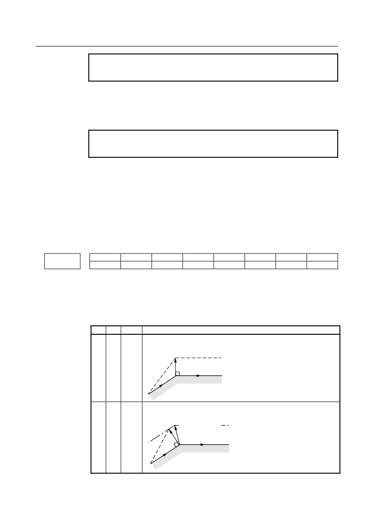
#1 SUV These bits are used to specify the type of startup/cancellation of cutter compensation or
tool nose radius compensation.
SUV
SUP
Type
Operation
0
0
Type A
A compensation vector perpendicular to the block next to the startup block or
the block preceding the cancellation block is output.
Tool nose radius center path /
G41
Tool center path
Programmed path
N2
N1
0
1
Type B
A compensation vector perpendicular to the startup block or cancellation block
and an intersection vector are output.
Intersection point
Tool nose radius center path /
Tool center path
Programmed path
G41
N2
N1
- 199 -
4.DESCRIPTION OF PARAMETERS
B-64310EN/02
SUV
SUP
Type
Operation
1
0
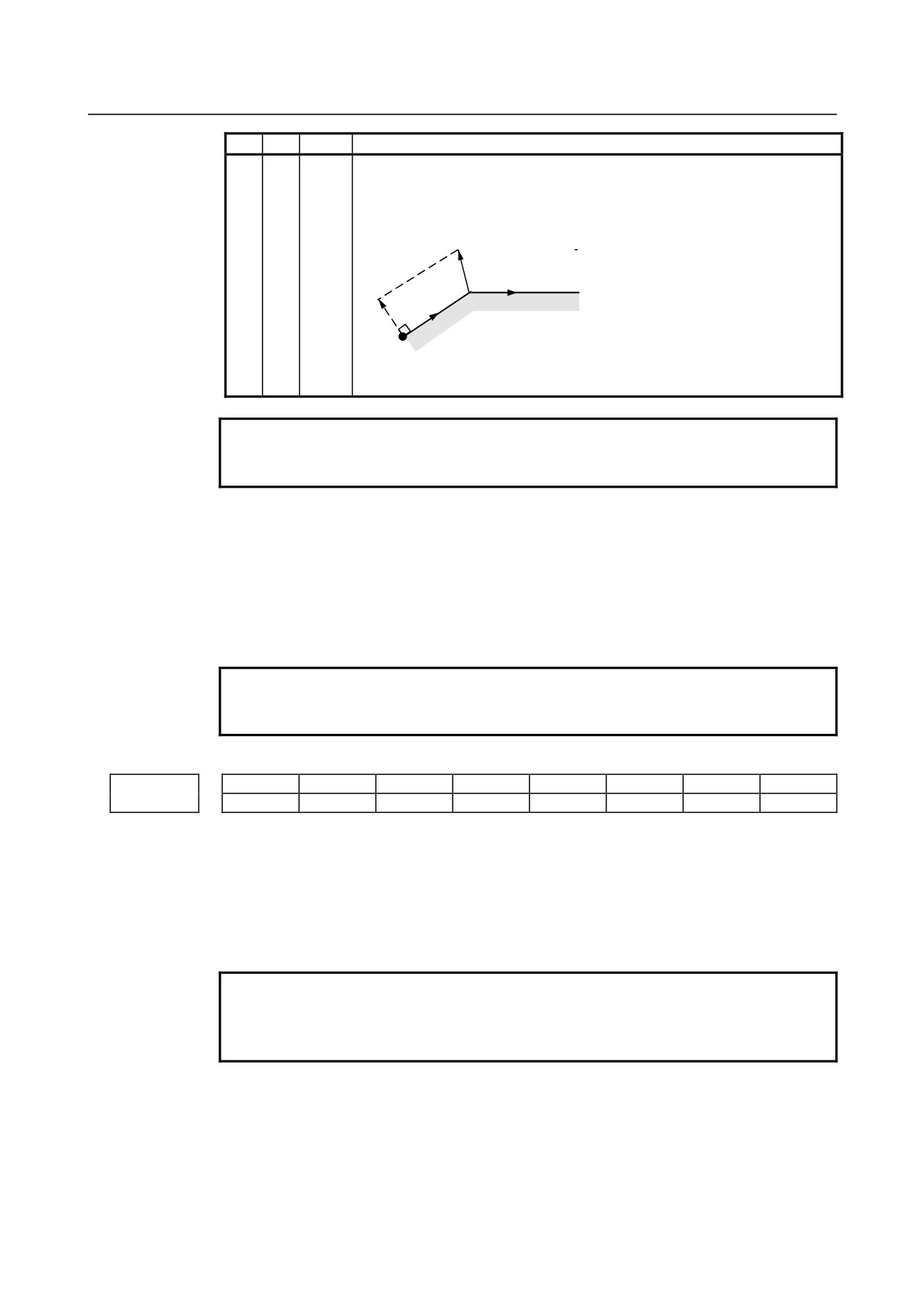
Type C
When the startup block or cancellation block specifies no movement
1
operation, the tool is shifted by the cutter compensation amount in a direction
perpendicular to the block next to the startup or the block before cancellation
block.
Intersection point
Tool nose radius center path /
G41
Tool center path
Shift
Programmed path
N3
N2
When the block specifies movement operation, the type is set according to the
SUP setting; if SUP is 0, type A is set, and if SUP is 1, type B is set.
NOTE
When SUV,SUP = 0,1 (type B), an operation equivalent to that of
FS0i-TC is performed.
#6
LVK Tool length compensation vector
0: Cleared by reset
1: Not cleared, but held by reset
#7
TGC A tool geometry offset based on a coordinate shift is:
0: Not canceled by reset.
1: Canceled by reset.
NOTE
This parameter is valid when tool geometry/wear compensation is
enabled (bit 6 (NGW) of parameter No. 8136 is 0).
#7
#6
#5
#4
#3
#2
#1
#0
TS1
ORC
5004
ODI
[Input type] Parameter input
[Data type] Bit path
#1 ORC The setting of a tool offset value is corrected as:
0: Diameter value
1: Radius value
NOTE
This parameter is valid only for an axis based on diameter
specification. For an axis based on radius specification, specify a
radius value, regardless of the setting of this parameter.
#2 ODI The setting of a cutter compensation value is corrected as:
0: Radius value
1: Diameter value
- 200 -
B-64310EN/02
4.DESCRIPTION OF PARAMETERS
#3 TS1 For touch sensor contact detection with the function for direct input of offset value
measured B (T series):
0: Four-contact input is used.
1: One-contact input is used.
#7
#6
#5
#4
#3
#2
#1
#0
TLE
QNI
PRC
CNI
5005
QNI
[Input type] Parameter input
[Data type] Bit path
#0 CNI On the offset screen, Y-axis offset screen, and macro screen, the [INP.C] soft key is:
0: Used.
1: Not used. (The [INP.C] soft key is not displayed.)
#2 PRC For direct input of a tool offset value or workpiece coordinate system shift amount:
0: The PRC signal is not used.
1: The PRC signal is used.
#5 QNI With the tool length measurement function (M series) or the function for direct input of
offset value measured B (T series), a tool compensation number is selected by:
0: Operation through the MDI panel by the operator
(selection based on cursor
operation).
1: Signal input from the PMC.
#6 TLE The "direct input of offset value measured B" function updates the offset value in offset
write mode:
0: Constantly.
1: During axis movement.
Axis movement assumes a positional deviation other than 0.
#7
#6
#5
#4
#3
#2
#1
#0
LVC
TGC
5006
TOS
[Input type] Parameter input
[Data type] Bit
#1 TGC If a T code is specified in a block where G50, G04, or G10 is specified:
0: No alarm is issued.
1: The alarm (PS0245) is issued.
#3 LVC A tool offset (geometry/wear) based on a tool movement and wear offset based on a
coordinate shift are:
0: Not canceled by reset.
1: Canceled by reset.
#6 TOS Set a tool length compensation operation.
0: Tool length compensation is performed by an axis movement.
1: Tool length compensation is performed by shifting the coordinate system.
- 201 -
4.DESCRIPTION OF PARAMETERS
B-64310EN/02
#7
#6
#5
#4
#3
#2
#1
#0
5008
MCR
CNV
CNC
[Input type] Parameter input
[Data type] Bit path
#1 CNC
#3 CNV These bits are used to select an interference check method in the cutter compensation or
tool nose radius compensation mode.
CNV
CNC
Operation
0
0
Interference check is enabled. The direction and the angle of an arc are checked.
0
1
Interference check is enabled. Only the angle of an arc is checked.
1
-
Interference check is disabled.
For the operation taken when the interference check shows the occurrence of an reference
(overcutting) , see the description of bit 5 (CAV) of parameter No. 19607.
NOTE
Checking of only the direction cannot be set.
#4 MCR If G41/G42 (cutter compensation or tool nose radius compensation) is specified in the
MDI mode, an alarm is:
0: Not raised.
1: Raised. (alarm PS5257)
#7
#6
#5
#4
#3
#2
#1
#0
TSD
GSC
5009
[Input type] Parameter input
[Data type] Bit path
NOTE
When at least one of these parameters is set, the power must be
turned off before operation is continued.
#0 GSC When the function for direct input of offset value measured B (T series) is used, an offset
write input signal is input from:
0: Machine side
1: PMC side
When the interlock function for each axis direction is enabled (when bit 3 (DIT) of
parameter No. 3003 is set to 0), switching can also be made between input from the
machine side and input from PMC side for the interlock function for each axis direction.
#4 TSD In the function for direct input of offset value measured B (T series), the movement
direction determination specifications:
0: Do not apply.
1: Apply.
This parameter is valid when four-contact input is used (bit 3 (TS1) of parameter No.
5004 is set to 0).
5010
Limit for ignoring the small movement resulting from cutter or tool nose radius compensation
[Input type] Setting input
[Data type] Real path
- 202 -