FANUC Series 0i-MODEL D, Series 0i Mate-MODEL D. PARAMETER MANUAL - page 6
B-64310EN/02
4.DESCRIPTION OF PARAMETERS
#7
#6
#5
#4
#3
#2
#1
#0
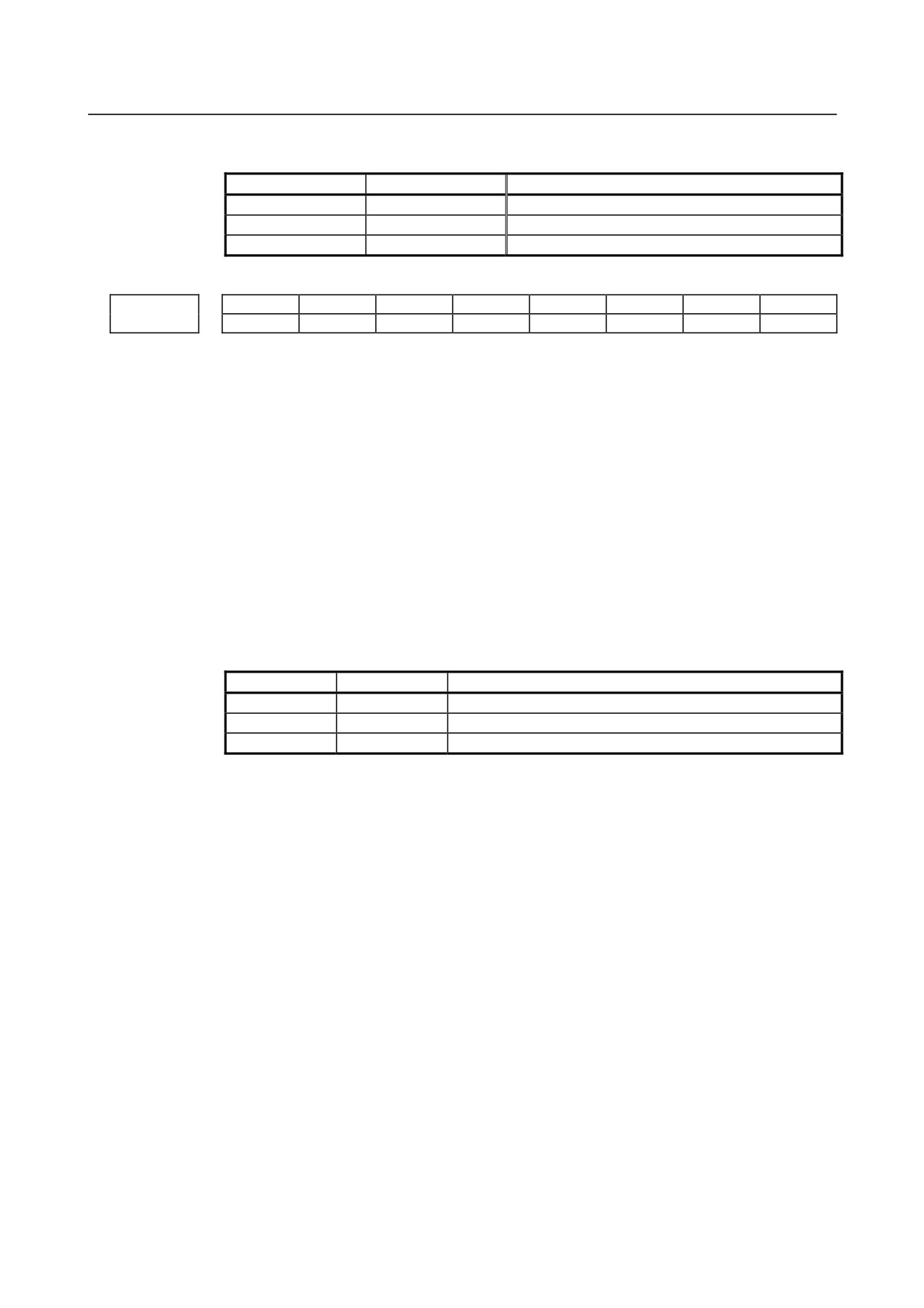
3203
MCL
MER
MZE
[Input type] Parameter input
[Data type] Bit path
#5 MZE After MDI operation is started, program editing during operation is:
0: Enabled
1: Disabled
#6 MER When the last block of a program has been executed at single block operation in the MDI
mode, the executed block is:
0: Not deleted
1: Deleted
NOTE
When MER is set to 0, the program is deleted if the end-of-record
mark (%) is read and executed. (The mark % is automatically
inserted at the end of a program.)
#7 MCL Whether a program prepared in the MDI mode is cleared by reset
0: Not deleted
1: Deleted
#7
#6
#5
#4
#3
#2
#1
#0
3204
MKP
PAR
[Input type] Parameter input
[Data type] Bit path
#0 PAR When a small MDI unit is used, characters "[" and "]" are:
0: Used as "[" and "]".
1: Used as "(" and ")".
NOTE
When a 2-path system is used, the setting for path 1 is followed.
#6 MKP When M02, M30, or EOR(%) is executed during MDI operation, the created MDI
program is:
0: Erased automatically.
1: Not erased automatically.
NOTE
If the bit 6 (MER) of parameter No. 3203 is 1, executing the last
block provides a choice of whether to automatically erase a created
program.
#7
#6
#5
#4
#3
#2
#1
#0
3205
OSC
PNS
TOK
[Input type] Parameter input
[Data type] Bit
- 143 -
4.DESCRIPTION OF PARAMETERS
B-64310EN/02
#2 TOK A WORD COPY or WORD MOVE on the program screen:
0: Is performed as usual.
1: Can also be performed on a record-by-record basis from a program to the key-in
buffer.
#3 PNS On the program screen, a search with the cursor keys is:
0: Performed.
1: Not performed.
#4 OSC On the offset screen, offset value erasure by a soft key is:
0: Enabled.
1: Disabled.
#7
#6
#5
#4
#3
#2
#1
#0
3206
NS2
S2K
PHS
MIF
[Input type] Parameter input
[Data type] Bit
#1 MIF Editing of the maintenance information screen is:
0: Not prohibited.
1: Prohibited.
#4 PHS Operation history signal selection:
0: Does not interact with parameters.
Operation history signal selection is added or deleted on the operation history signal
selection screen.
Changing the settings of parameters Nos. 12801 to 12820, Nos. 12841 to 12860, or
Nos. 12881 to 12900 has no effect on operation history signal selection.
Changes to the signals of the addresses specified by parameters Nos. 12801 to 12820,
Nos. 12841 to 12860, or Nos. 12881 to 12900 are not recorded in the history.
1: Interacts with parameters.
Operation history signal selection can be performed either on the operation history
signal selection screen or by setting parameters.
NOTE
Setting this parameter to 1 reflects the current operation history
signal selection data on parameters Nos. 12801 to 12900.
#5 S2K In CNC screen dual display function,
0: Key control is selected by DI signal <G295.7>.
1: Key control is selected by pushing at left upper corner on the screen. (Touch panel
only)
#7 NS2 CNC screen dual display function is:
0: Disabled.
1: Enabled.
#7
#6
#5
#4
#3
#2
#1
#0
3207
TPP
VRN
EXS
[Input type] Parameter input
[Data type] Bit
- 144 -
B-64310EN/02
4.DESCRIPTION OF PARAMETERS
#0 EXS The machine menu function is:
0: Disabled.
1: Enabled.
#5 VRN On the custom macro variable screen, the variable names of common variables #500 to
#549 are:
0: Not displayed.
1: Displayed.
#6 TPP When a virtual MDI key is pressed, signal TPPRS<F006.0> is
0: Not output.
1: Output
#7
#6
#5
#4
#3
#2
#1
#0
PSC
SKY
3208
SKY
[Input type] Setting input
[Data type] Bit
#0 SKY The function key
on the MDI panel is:
0: Enabled.
1: Disabled.
#5 PSC When the path is switched based on the path switch signal:
0: The screen display is switched to the last selected screen of the path.
1: The same screen as for the path before switching is displayed.
3210
Program protection
[Input type] Parameter input
[Data type] 2-word
[Valid data range] 0 to 99999999
This parameter sets a password for protecting program Nos. 9000 to 9999. When a value
other than zero is set in this parameter and this value differs from the keyword set in
parameter No.3211, bit 4 (NE9) of parameter No.3202 for protecting program Nos. 9000
to 9999 is automatically set to 1.
This disables the editing of program Nos. 9000 to 9999. Until the value set as the
password is set as a keyword, NE9 cannot be set to 0 and the password cannot be
modified.
NOTE
1 The state where password ≠ 0 and password ≠ keyword is referred
to as the locked state. When an attempt is made to modify the
password by MDI input operation in this state, the warning
message "WRITE PROTECTED" is displayed to indicate that the
password cannot be modified. When an attempt is made to modify
the password with G10 (programmable parameter input), alarm
(PS0231) is issued.
2 When the value of the password is not 0, the parameter screen
does not display the password. Care must be taken in setting a
password.
- 145 -
4.DESCRIPTION OF PARAMETERS
B-64310EN/02
3211
Program protection key
[Input type] Parameter input
[Data type] 2-word
[Valid data range] 0 to 99999999
When the value set as the password (set in parameter No.3210) is set in this parameter,
the locked state is released and the user can now modify the password and the value set in
bit 4 (NE9) of parameter No.3202.
NOTE
The value set in this parameter is not displayed. When the power is
turned off, this parameter is set to 0.
3216
Increment in sequence numbers inserted automatically
[Input type] Setting input
[Data type] 2-word path
[Valid data range] 0 to 9999
Set the increment for sequence numbers for automatic sequence number insertion (when
bit 5 (SEQ) of parameter No. 0000, is set to 1.)
3227
Selection of a block number of machine operation menu data
[Input type] Parameter input
[Data type] Byte
[Valid data range] 0 to 98
This parameter select a block number to use from the inside of the machine operation
menu definition file which was stored in the FROM in the machine operation menu
function. If "0", "the value except the data range" or either of "the block number not to be
defining" is set, the machine operation menu function is disabled.
3241
Character blinking in the AI advanced preview control/AI contour control mode (first character)
3242
Character blinking in the AI advanced preview control/AI contour control mode (second character)
3243
Character blinking in the AI advanced preview control/AI contour control mode (third character)
3244
Character blinking in the AI advanced preview control/AI contour control mode (fourth character)
3245
Character blinking in the AI advanced preview control/AI contour control mode (fifth character)
3246
Character blinking in the AI advanced preview control/AI contour control mode (sixth character)
3247
Character blinking in the AI advanced preview control/AI contour control mode (seventh character)
[Input type] Parameter input
[Data type] Word path
- 146 -
B-64310EN/02
4.DESCRIPTION OF PARAMETERS
[Valid data range] 0, 32 to 95
Set the first to seventh blinking characters in the AI advanced preview control/AI contour
control mode by using ASCII codes represented as decimal numbers.
When all parameters are set to 0, "AI APC" blinks for AI advanced preview control or
"AICC" blinks for AI contour control or "AICC 2" blinks for AI contour control II.
Code numbers 032 to 095 in the Appendix A, "CHARACTER CODE LIST" can be set.
Character blinking in the advanced preview control mode (first character)
3251
Character blinking in the advanced preview control mode (second character)
3252
Character blinking in the advanced preview control mode (third character)
3253
Character blinking in the advanced preview control mode (fourth character)
3254
Character blinking in the advanced preview control mode (fifth character)
3255
Character blinking in the advanced preview control mode (sixth character)
3256
Character blinking in the advanced preview control mode (seventh character)
3257
[Input type] Parameter input
[Data type] Word path
[Valid data range] 0, 32 to 95
Set the first to seventh blinking characters in the advanced preview control mode by using
ASCII codes represented as decimal numbers.
When 0 is set in all of these parameters, "APC" blinks.
Code numbers 032 to 095 in the Appendix A, "CHARACTER CODE LIST" can be set.
#7
#6
#5
#4
#3
#2
#1
#0
3280
NLC
[Input type] Parameter input
[Data type] Bit
#0 NLC Dynamic display language switching is:
0: Enabled.
1: Disabled.
When dynamic display language switching is disabled, the language setting screen is not
displayed. In this case, change the setting of parameter No. 3281 on the parameter screen
then turn on the power again to switch the display language.
3281
Display language
[Input type] Parameter input
[Data type] Byte
[Valid data range] 0 to 18
Select a display language from the following:
0 : English
- 147 -
4.DESCRIPTION OF PARAMETERS
B-64310EN/02
1 : Japanese
2 : German
3 : French
4 : Chinese(traditional characters)
5 : Italian
6 : Korean
7 : Spanish
8 : Dutch
9 : Danish
10 : Portuguese
11 : Polish
12 : Hungarian
13 : Swedish
14 : Czech
15 : Chinese(simplified characters)
16 : Russian
17 : Turkish
18 : Bulgarian
If a number not indicated above is set, English is selected.
NOTE
The following language is optional function.
- Bulgarian
If the number of the language which an option isn't applied to is set,
English is selected.
#7
#6
#5
#4
#3
#2
#1
#0
3290
KEY
MCM
IWZ
WZO
GOF
WOF
[Input type] Parameter input
[Data type] Bit path
#0 WOF Setting the tool offset value (tool wear offset) by MDI key input is:
0: Not disabled.
1: Disabled. (With parameter No.3294 and No.3295, set the offset number range in
which updating the setting is to be disabled.)
NOTE
When tool offset memory A is selected with the M series, the tool
offset set in the parameter WOF is followed even if geometric
compensation and wear compensation are not specified with the T
series.
#1 GOF Setting the tool geometry offset value by MDI key input is:
0: Not disabled.
1: Disabled. (With parameter No.3294 and No.3295, set the offset number range in
which updating the setting is to be disabled.)
#3 WZO Setting a workpiece zero point offset value and workpiece shift value (T series) by MDI
key input is:
0: Not disabled.
1: Disabled.
- 148 -

B-64310EN/02
4.DESCRIPTION OF PARAMETERS
#4 IWZ Setting a workpiece zero point offset value or workpiece shift value (T series) by MDI
key input in the automatic operation activation or halt state is:
0: Not disabled.
1: Disabled.
#6 MCM Setting a custom macro variable by MDI key input is:
0: Enabled in any mode.
1: Enabled only in the MDI mode.
#7 KEY For memory protection keys:
0: The KEY1, KEY2, KEY3, and KEY4 signals are used.
1: Only the KEY1 signal is used.
NOTE
1 The functions of the signals depend on whether KEY=0 or KEY=1.
When KEY = 0:
- KEY1: Enables a tool offset value, workpiece zero point offset
value, and workpiece shift value (T series) to be input.
- KEY2: Enables setting data, macro variables, and tool life
management value to be input.
- KEY3: Enables program registration and editing.
- KEY4: Enables PMC data (counter and data table) to be input.
When KEY = 1:
- KEY1: Enables program registration and editing, and enables
PMC parameter input.
- KEY2 to KEY4: Not used
2 When a 2-path system is used, the setting for path 1 is followed.
#7
#6
#5
#4
#3
#2
#1
#0
3291
WPT
[Input type] Parameter input
[Data type] Bit path
#0 WPT The input of the tool wear compensation amount is:
0: Enabled according to memory protection key signal KEY1.
1: Enabled, regardless of the memory protection key signal KEY1.
3294
Start number of tool offset values whose input by MDI is disabled
3295
Number of tool offset values (from the start number) whose input by MDI is disabled
[Input type] Parameter input
[Data type] Word path
[Valid data range] 0 to Tool compensation count - 1
When the modification of tool offset values by MDI key input is to be disabled using bit
0 (WOF) of parameter No.3290 and bit 1 (GOF) of parameter No.3290, parameter
Nos.3294 and 3295 are used to set the range where such modification is disabled. In
parameter No.3294, set the offset number of the start of tool offset values whose
modification is disabled. In parameter No.3295, set the number of such values. In the
following cases, however, none of the tool offset values may be modified:
• When 0 or a negative value is set in parameter No.3294
• When 0 or a negative value is set in parameter No.3295
- 149 -
4.DESCRIPTION OF PARAMETERS
B-64310EN/02
• When a value greater than the maximum tool offset number is set in parameter
No.3294
In the following case, a modification to the values ranging from the value set in parameter
No.3294 to the maximum tool offset number is disabled:
When the value of parameter No.3294 added to the value of parameter No.3295
exceeds the maximum tool offset number
When the offset value of a prohibited number is input through the MDI panel, the
warning "WRITE PROTECT" is issued.
[Example] When the following parameter settings are made, modifications to both of the tool
geometry offset values and tool wear offset values corresponding to offset numbers 51 to
60 are disabled:
• Bit 1 (GOF) of parameter No.3290 = 1 (to disable tool geometry offset value
modification)
• Bit
0
(WOF) of parameter No.3290
= 1 (to disable tool wear offset value
modification)
• Parameter No.3294 = 51
• Parameter No.3295 = 10
If the setting of bit 0 (WOF) of parameter No.3290 is set to 0 without modifying the other
parameter settings above, tool geometry offset value modification only is disabled, and
tool wear offset value modification is enabled.
#7
#6
#5
#4
#3
#2
#1
#0
3299
PKY
[Input type] Setting input
[Data type] Bit
#0 PKY "Parameter write enable" is:
0: Set on the setting screen (bit 0 (PWE) of setting parameter No.8900).
1: Set by the memory protection signal KEYP<G046.0>.
#7
#6
#5
#4
#3
#2
#1
#0
3301
HDC
H16
[Input type] Parameter input
[Data type] Bit path
#0 H16 Bit map data of screen hard copies uses:
0:
256 colors.
1:
16 colors.
#7 HDC A screen hard copy function is:
0: Disabled.
1: Enabled.
4.19 PARAMETERS OF PROGRAMS (1 OF 3)
#7
#6
#5
#4
#3
#2
#1
#0
SMX
UVW
3400
SMX
[Input type] Parameter input
[Data type] Bit path
- 150 -
B-64310EN/02
4.DESCRIPTION OF PARAMETERS
#4 UVW When G code system B or C is selected:
0: The U, V, W, and H commands are not the incremental commands of the X-, Y- , Z-,
and C-axes.
1: The U, V, W, and H commands are the incremental commands of the X-, Y- , Z-,
and C-axes.
NOTE
1 When U-, V-, and W-axes are present, the U, V, and W commands
are assumed to be the commands for these axes. That is, they
are not the incremental commands of the X-, Y-, and Z-axes.
2 If this parameter is set to 1, it is impossible to use U, V, or W as the
specified address (parameter No. 3460) of the second auxiliary
function for G code system B or C.
3 If this parameter is set to 1, the same operation as that of the
FS0i-TC is assumed.
#6 SMX An S code specified in a block that specifies G92 (G50 with G code system A of the T
series) is:
0: Regarded as a maximum spindle speed command.
1: Not regarded as a maximum spindle speed command (but regarded as a spindle
speed command).
#7
#6
#5
#4
#3
#2
#1
#0
GSC
GSB
ABS
MAB
DPI
3401
ABS
MAB
DPI
[Input type] Parameter input
[Data type] Bit path
#0 DPI When a decimal point is omitted in an address that can include a decimal point
0: The least input increment is assumed. (Normal decimal point input)
1: The unit of mm, inches, degree, or second is assumed. (Pocket calculator type
decimal point input)
#4 MAB Switching between the absolute and incremental commands in MDI operation
0: Performed by G90 or G91
1: Depending on the setting of bit 5 (ABS) of parameter No.3401
NOTE
When G code system A of the T series is used, this parameter is
invalid.
#5 ABS Program command in MDI operation
0: Assumed as an incremental command
1: Assumed as an absolute command
NOTE
ABS is valid when bit 4 (MAB) of parameter No.3401 is set to 1.
When G code system A of the T series is used, this parameter is
invalid.
- 151 -
4.DESCRIPTION OF PARAMETERS
B-64310EN/02
#6 GSB The G code system is set.
#7 GSC
GSC
GSB
G code
0
0
G code system A
0
1
G code system B
1
0
G code system C
#7
#6
#5
#4
#3
#2
#1
#0
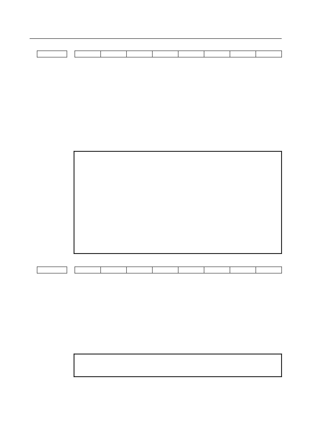
G23
CLR
FPM
G91
G01
3402
G23
CLR
G70
G91
G19
G18
G01
[Input type] Parameter input
[Data type] Bit path
#0 G01 G01 Mode entered when the power is turned on or when the control is cleared
0: G00 mode (positioning)
1: G01 mode (linear interpolation)
#1 G18 Plane selected when power is turned on or when the control is cleared
0: G17 mode (plane XY)
1: G18 mode (plane ZX)
#2 G19 Plane selected when power is turned on or when the control is cleared
0: The setting of bit 1 (G18) of parameter No.3402 is followed.
1: G19 mode (plane YZ)
When this bit is set to 1, set bit 1 (G18) of parameter No.3402 to 0.
G19
G18
G17, G18, or G19 mode
0
0
G17 mode (X-Y plane)
0
1
G18 mode (Z-X plane)
1
0
G19 mode (Y-Z plane)
#3 G91 When the power is turned on or when the control is cleared
0: G90 mode (absolute command)
1: G91 mode (incremental command)
#4 FPM At power-on time or in the cleared state:
0: G99 or G95 mode (feed per revolution) is set.
1: G98 or G94 mode (feed per minute) is set.
#5 G70 The commands for inch input and metric input are:
0: G20 (inch input) and G21 (metric input).
1: G70 (inch input) and G71 (metric input).
#6 CLR Reset button on the MDI panel, external reset signal, reset and rewind
signal, and
emergency stop signal
0: Cause reset state.
1: Cause clear state.
For the reset and clear states, refer to Appendix in the OPERATOR’S MANUAL.
#7 G23 When the power is turned on
0: G22 mode (stored stroke check on)
1: G23 mode (stored stroke check off)
- 152 -
B-64310EN/02
4.DESCRIPTION OF PARAMETERS
#7
#6
#5
#4
#3
#2
#1
#0
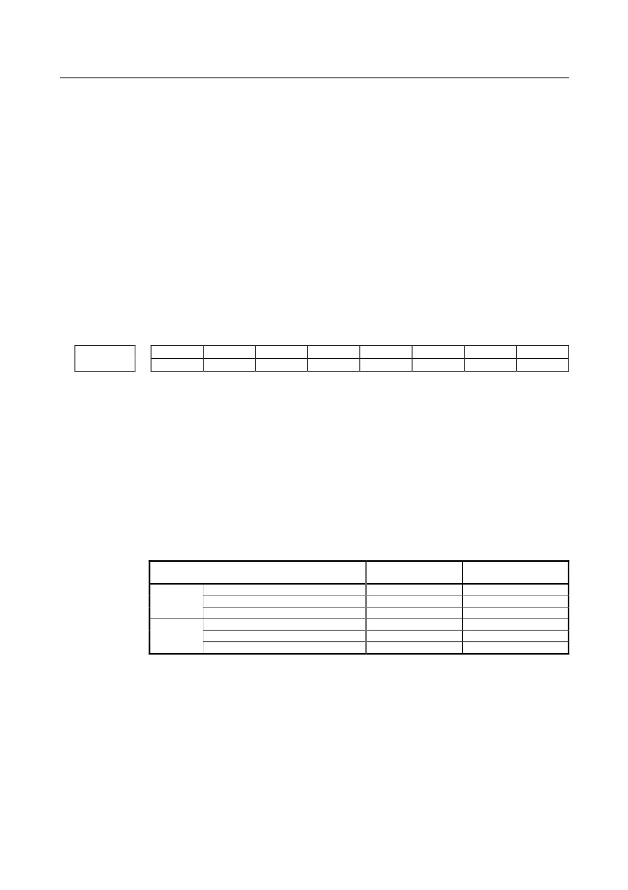
3403
ADB
CIR
[Input type] Parameter input
[Data type] Bit path
#5 CIR When neither the distance (I, J, K) from a start point to the center nor an arc radius (R) is
specified in circular interpolation (G02, G03) or helical interpolation (G02, G03):
0: The tool moves to an end point by linear interpolation.
1: An alarm PS0022 is issued.
#6 ADB When the same address two or more times are specified in one block:
0: The address specified last is valid.
1: It is treated as a program error and the alarm PS5074, "ADDRESS DUPLICATION
ERROR" is issued.
NOTE
1 You can specify any number of G codes in the same block as long
as they belong to different groups. Specifying G codes belonging to
the same group causes the alarm PS5074. You can however
specify any number of G90 and G91 codes in the same block as
they cause no alarm.
2 When bit 7 (M3B) of parameter No.3404 is set to 1, up to three M
codes can be specified in the same block. Specifying more than
three results in the alarm PS5074.
3 When G code system A is used with the lathe system, specifying
an absolute programming and incremental programming for the
same axis causes the alarm PS5074.
4 The alarm is not caused by blocks which call a custom macro or
argument specification I/II of execution macro.
#7
#6
#5
#4
#3
#2
#1
#0
3404
M3B
M02
M30
SBP
NOB
[Input type] Parameter input
[Data type] Bit path
#0 NOB When a program is executed, a block consisting of an O, N, or EOB is:
0: Not ignored.
1: Ignored.
#2 SBP In an external device subprogram call (M198), the address P format is based on:
0: File number specification
1: Program number specification
NOTE
In memory card operation, the program number specification
format is used, regardless of the setting of this parameter.
- 153 -
4.DESCRIPTION OF PARAMETERS
B-64310EN/02
#4 M30 When M30 is specified in a memory operation:
0: M30 is sent to the machine, and the head of the program is automatically searched
for. So, when the ready signal FIN is returned and a reset or reset and rewind
operation is not performed, the program is executed, starting from the beginning.
1: M30 is sent to the machine, but the head of the program is not searched for. (The
head of the program is searched for by the reset and rewind signal.)
#5 M02 When M02 is specified in memory operation
0: M02 is sent to the machine, and the head of the program is automatically searched
for. So, when the end signal FIN is returned and a reset or reset and rewind
operation is not performed, the program is executed, starting from the beginning.
1: M02 is sent to the machine, but the head of the program is not searched for. (The
head of the program is searched for by the reset and rewind signal.)
#7 M3B The number of M codes that can be specified in one block
0: One
1: Up to three
#7
#6
#5
#4
#3
#2
#1
#0
DDP
CCR
DWL
AUX
3405
DWL
AUX
[Input type] Parameter input
[Data type] Bit path
#0 AUX When the second auxiliary function is specified in the calculator-type decimal point input
format or with a decimal point, the multiplication factor for a value output (onto the code
signal) relative to a specified value is such that:
0: The same multiplication factor is used for both of metric input and inch input.
1: A multiplication factor used for inch input is 10 times greater than that used for
metric input.
When the second auxiliary function is specified in the calculator-type decimal point input
format or with a decimal point, the value output onto the code signal is a specified value
multiplied by a value indicated below.
Increment system
Parameter AUX=0
Parameter AUX=1
Metric
IS-A for reference axis
100 times
100 times
input
IS-B for reference axis
1000 times
1000 times
system
IS-C for reference axis
10000 times
10000 times
IS-A for reference axis
100 times
1000 times
Inch input
IS-B for reference axis
1000 times
10000 times
system
IS-C for reference axis
10000 times
100000 times
#1 DWL The dwell time (G04) is:
0: Always dwell per second.
1: Dwell per second in the feed per minute mode, or dwell per rotation in the feed per
rotation mode.
#4 CCR Addresses used for chamfering
0: Address is “I”, “J”, or “K”.
In direct drawing dimension programming, addresses ",C", ",R", and ",A" (with
comma) are used in stead of "C", "R", and "A".
1: Address is “C”.
Addresses used for direct drawing dimension programming are "C", "R", and "A"
without comma.
- 154 -
B-64310EN/02
4.DESCRIPTION OF PARAMETERS
NOTE
If this bit (CCR) is set to 0, the function for changing the
compensation direction by specifying I, J, or K in a G01 block in the
tool nose radius compensation mode cannot be used.
If this bit (CCR) is set to 1 when address C is used as an axis
name, the chamfer function cannot be used.
#5 DDP Angle commands by direct drawing dimension programming
0: Normal specification
1: A supplementary angle is given.
#7
#6
#5
#4
#3
#2
#1
#0
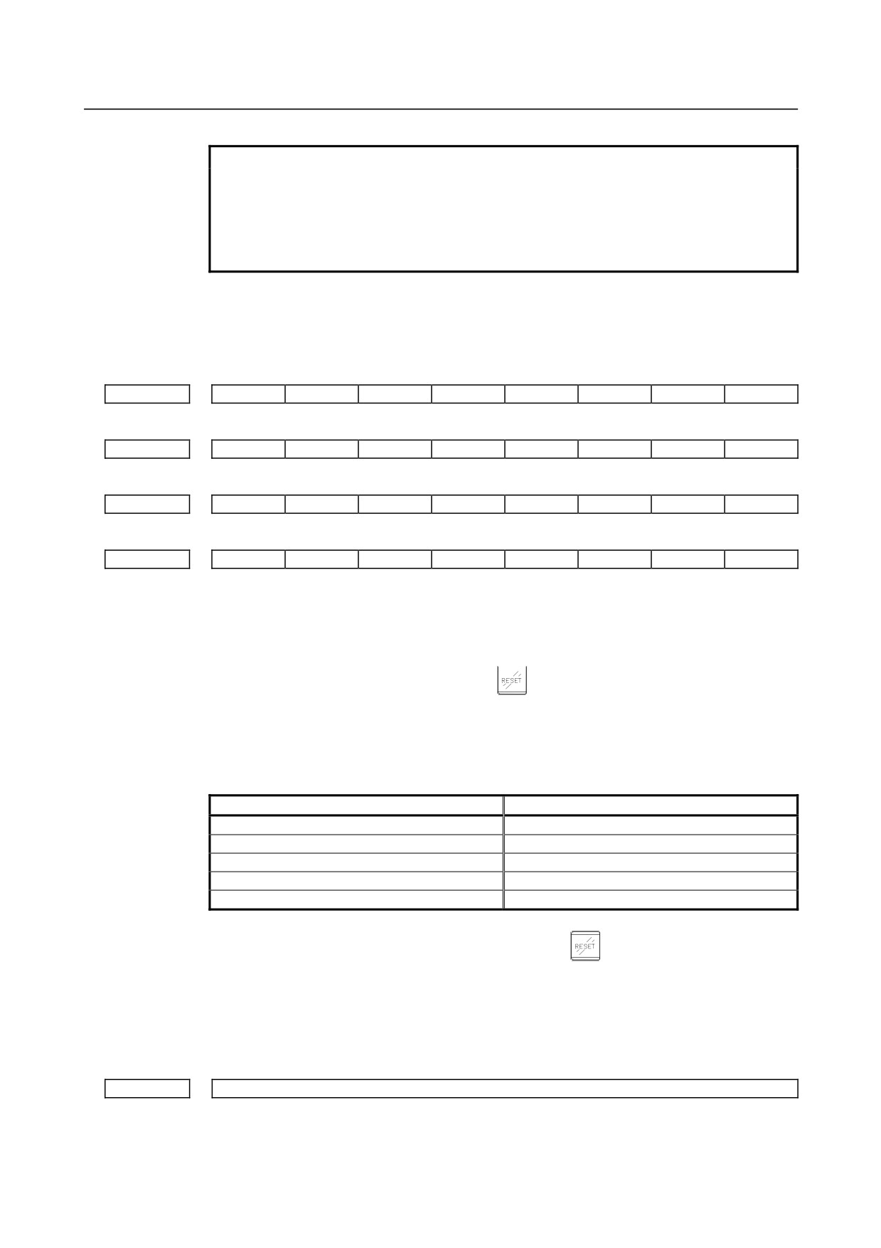
3406
C07
C06
C05
C04
C03
C02
C01
#7
#6
#5
#4
#3
#2
#1
#0
3407
C15
C14
C13
C12
C11
C10
C09
C08
#7
#6
#5
#4
#3
#2
#1
#0
3408
C23
C22
C21
C20
C19
C18
C17
C16
#7
#6
#5
#4
#3
#2
#1
#0
3409
CFH
C30
C29
C28
C27
C26
C25
C24
[Input type] Parameter input
[Data type] Bit
C01 to C30 If bit 6 (CLR) of parameter No.3402 is set to 1, set a group of G codes to be placed in the
cleared state when the CNC is reset by the
key of the MDI panel, the external reset
signal, the reset & rewind signal, or the emergency stop signal.
The table below indicates the correspondence between bits and G code groups
The setting of a bit has the following meaning:
0: Places the G code group in the cleared state.
1: Does not place G code group in the cleared state.
Parameter
G code group
C01
01
C02
02
C03
03
:
:
C30
30
#7 CFH When bit 6 (CLR) of parameter No.3402 is 1, the
key on the MDI panel, the
external reset signal, the reset and rewind signal, or emergency stop will,
0: Clear F codes, H codes (for the M series), D codes (for the M series), and T codes
(for the T series).
1: Not clear F codes, H codes (for the M series), D codes (for the M series), and T
codes (for the T series).
3410
Tolerance of arc radius
[Input type] Setting input
[Data type] Real path
- 155 -
4.DESCRIPTION OF PARAMETERS
B-64310EN/02
[Unit of data] mm, inch (input unit)
[Min. unit of data] Depend on the increment system of the reference axis
[Valid data range] 0 or positive 9 digit of minimum unit of data (refer to the standard parameter setting table
(B))
(When the increment system is IS-B, 0.0 to +999999.999)
When a circular interpolation command is executed, the tolerance for the radius between
the start point and the end point is set.
NOTE
When the setting is 0, the difference between the arc radius values
is not checked.
3411
M code preventing buffering 1
3412
M code preventing buffering 2
:
3420
M code preventing buffering 10
[Input type] Parameter input
[Data type] 2-word path
[Valid data range] 3 to 99999999
Set M codes that prevent buffering the following blocks. If processing directed by an M
code must be performed by the machine without buffering the following block, specify
the M code.
M00, M01, M02, and M30 always prevent buffering even when they are not specified in
these parameters.
3421
Range specification 1 of M codes that do not perform buffering (lower limit)
3422
Range specification 1 of M codes that do not perform buffering (upper limit)
3423
Range specification 2 of M codes that do not perform buffering (lower limit)
3424
Range specification 2 of M codes that do not perform buffering (upper limit)
3425
Range specification 3 of M codes that do not perform buffering (lower limit)
3426
Range specification 3 of M codes that do not perform buffering (upper limit)
3427
Range specification 4 of M codes that do not perform buffering (lower limit)
3428
Range specification 4 of M codes that do not perform buffering (upper limit)
3429
Range specification 5 of M codes that do not perform buffering (lower limit)
3430
Range specification 5 of M codes that do not perform buffering (upper limit)
3431
Range specification 6 of M codes that do not perform buffering (lower limit)
3432
Range specification 6 of M codes that do not perform buffering (upper limit)
[Input type] Parameter input
[Data type] 2-word path
[Valid data range] 3 to 99999999
- 156 -
B-64310EN/02
4.DESCRIPTION OF PARAMETERS
When a specified M code is within the range specified with parameter Nos.3421 and 3422,
3423 and 3424, 3425 and 3426, 3427 and 3428, 3429 and 3430, or 3431 and 3432,
buffering for the next block is not performed until the execution of the block is
completed.
NOTE
1 M00, M01, M02, and M30 are M codes that do not perform
buffering, regardless of parameter setting.
M98, M99, M codes for calling subprograms, and M codes for
calling custom macros are M codes that performs buffering,
regardless of parameter setting.
2 If the minimum value is greater than the maximum value, the
setting is invalid.
3 If there is only one data item, the minimum value must be equal to
the maximum value.
#7
#6
#5
#4
#3
#2
#1
#0
3450
BDX
AUP
[Input type] Parameter input
[Data type] Bit path
#0 AUP The second auxiliary function specified in the calculator-type decimal point input format,
with a decimal point, or with a negative value is:
0: Disabled.
1: Enabled.
If the second auxiliary function is specified after setting this bit to 0, the following
operation results:
1.
When a value is specified without a decimal point
A specified value is output onto the code signal without modification, regardless of
the setting of the calculator-type decimal point input format (with bit 0 (DPI) of
parameter No. 3401).
2.
When a value is specified with a decimal point
The alarm (PS0007) is issued.
3.
When a negative value is specified
The alarm (PS0006) is issued.
#7
BDX This parameter prevents the unit of the argument from depending on the setting of bit 2
(BCD) of parameter No. 8132 when a subprogram call by an ASCII code is performed
with the address (specified by parameter No. 3460) of the second auxiliary function.
0: When bit 0 (AUP) of parameter No. 3450 is 1, the unit of the argument depends on
the setting of bit 2 (BCD) of parameter No. 3450.
1: The same unit of the argument is used. The unit when bit 2 (BCD) of parameter
No. 8132 is 1 is specified.
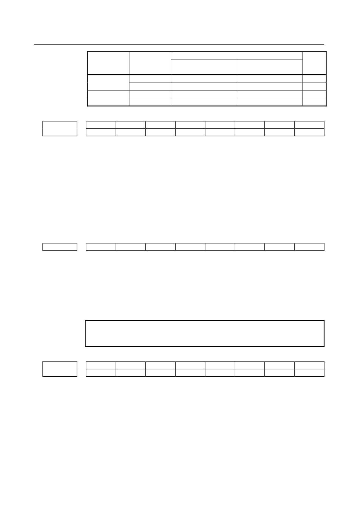
[Example]
A setting is made so that address B is used to call O9004, and the program O1 below
is executed with parameter No.3460 = 66.
O1 O9004
B2
#500 = #146
M30
M99
When the increment system is IS-B, and metric input is used, #500 assumes a value
indicated in the table below.
- 157 -
4.DESCRIPTION OF PARAMETERS
B-64310EN/02
BDX=0
Parameter DPI
Parameter AUP
Parameter
Parameter
BDX=1
(No.3401#0)
(No.3450#0)
BCD(No.8132#2)=0
BCD(No.8132#2)=1
0
2.000
2.000
2.000
0
1
2.000
0.002
0.002
0
2.000
2.000
2.000
1
1
2.000
2.000
2.000
#7
#6
#5
#4
#3
#2
#1
#0
NBN
3451
NBN
GQS
[Input type] Parameter input
[Data type] Bit path
#0 GQS When threading is specified, the threading start angle shift function (Q) is:
0: Disabled.
1: Enabled.
#4 NBN If bit 0 (NOB) of parameter No.3404 is set to 1, a block including just N is:
0: Ignored.
1: Not ignored but handled as a single block.
(For a block containing only N, bit 0 (NOB) of parameter No.3404 is ignored.)
#7
#6
#5
#4
#3
#2
#1
#0
3452
EAP
[Input type] Parameter input
[Data type] Bit path
#7 EAP When bit 0 (ADX) of parameter No.3455 is set to 1, calculator-type decimal point input
at a macro calling argument address is:
0: Enabled.
1: Disabled.
NOTE
This parameter is valid when bit 0 (DPI) of parameter No.3401 is
set to 0.
#7
#6
#5
#4
#3
#2
#1
#0
CRD
3453
[Input type] Setting input
[Data type] Bit path
#0 CRD If the functions of chamfering or corner R and direct drawing dimension programming
are both enabled,
0: Chamfering or corner R is enabled.
1: Direct drawing dimension programming is enabled.
Specify which function is used when both the chamfering/corner R function and the
drawing dimension programming function are enabled.
- 158 -
B-64310EN/02
4.DESCRIPTION OF PARAMETERS
#7
#6
#5
#4
#3
#2
#1
#0
3454
G1B
[Input type] Parameter input
[Data type] Bit path
#4 G1B In programmable parameter input, specifying a change to a specific bit parameter is:
0: Disabled.
1: Enabled. (A bit number is specified with Q_.)
#7
#6
#5
#4
#3
#2
#1
#0
3455
AXDx
[Input type] Parameter input
[Data type] Bit axis
#0 AXDx If a decimal point is omitted for an axis address with which a decimal point can be used,
the value is determined:
0: In accordance with the least input increment. (Normal decimal point input)
1: In millimeters, inches, or seconds. (calculator-type decimal point input)
NOTE
This parameter specifies the calculator-type decimal point input
function for each axis.
For the same axis name, be sure to make the same setting.
3460
Second auxiliary function specification address
[Input type] Parameter input
[Data type] Byte path
[Valid data range] 65to67, 85to87
Specify which of A, B, C, U, V, and W is to be used as the address for specifying the
second auxiliary function. If an address used as an axis name is specified, the second
auxiliary function is disabled.
Name
A
B
C
U
V
W
Setting value
65
66
67
85
86
87
Address B is assumed when a value other than the above is set.
However, the name U, V, or W can be used with the T series only when G code system B
or C is used. When a value from 85 to 87 is specified with G code system A, the
specification address for the second auxiliary function is B.
4.20 PARAMETERS OF PITCH ERROR COMPENSATION
#7
#6
#5
#4
#3
#2
#1
#0
3601
EPC
[Input type] Parameter input
[Data type] Bit path
- 159 -
4.DESCRIPTION OF PARAMETERS
B-64310EN/02
NOTE
When this parameter is set, the power must be turned off before
operation is continued.
#1 EPC The pitch error compensation on an axis of Cs contour control on the slave spindle side
during simple synchronous spindle control (M series) is:
0: The same as that on the master spindle.
1: Just for the slave spindle.
#7
#6
#5
#4
#3
#2
#1
#0
3605
BDPx
[Input type] Parameter input
[Data type] Bit axis
NOTE
When this parameter is set, the power must be turned off before
operation is continued.
#0 BDPx Both-direction pitch error compensation is:
0: Not used.
1: Used.
NOTE
The both-direction pitch error compensation option is required.
3620
Number of the pitch error compensation position for the reference position for each axis
NOTE
When this parameter is set, the power must be turned off before
operation is continued.
[Input type] Parameter input
[Data type] Word axis
[Valid data range] 0 to 1023
Set the number of the pitch error compensation position for the reference position for
each axis.
3621
Number of the pitch error compensation position at extremely negative position for each axis
NOTE
When this parameter is set, the power must be turned off before
operation is continued.
[Input type] Parameter input
[Data type] Word axis
[Valid data range] 0 to 1023
Set the number of the pitch error compensation position at the extremely negative
position for each axis.
- 160 -
B-64310EN/02
4.DESCRIPTION OF PARAMETERS
3622
Number of the pitch error compensation position at extremely positive position for each axis
NOTE
When this parameter is set, the power must be turned off before
operation is continued.
[Input type] Parameter input
[Data type] Word axis
[Valid data range] 0 to 1023
Set the number of the pitch error compensation position at the extremely positive position
for each axis.
This value must be larger than set value of parameter (No.3620).
3623
Magnification for pitch error compensation for each axis
NOTE
When this parameter is set, the power must be turned off before
operation is continued.
[Input type] Parameter input
[Data type] Byte axis
[Valid data range] 0 to 100
Set the magnification for pitch error compensation for each axis.
If the magnification is set to 1, the same unit as the detection unit is used for
the
compensation data.
If 0 is set, compensation is not performed.
3624
Interval between pitch error compensation positions for each axis
NOTE
When this parameter is set, the power must be turned off before
operation is continued.
[Input type] Parameter input
[Data type] Real axis
[Unit of data] mm, inch, degree (machine unit)
[Min. unit of data] Depend on the increment system of the applied axis
[Valid data range] See the description below.
The pitch error compensation positions are arranged with equal spacing. The space
between two adjacent positions is set for each axis. The minimum interval between pitch
error compensation positions is limited and obtained from the following equation:
Minimum interval between pitch error compensation positions = maximum feedrate/7500
Unit : Minimum interval between pitch error compensation positions: mm, inch, deg
Maximum feedrate: mm/min, inch/min, deg/min
[Example] When the maximum feedrate is 15000 mm/min, the minimum interval between pitch error
compensation positions is 2 mm.
3625
Travel distance per revolution in pitch error compensation of rotation axis type
NOTE
When this parameter is set, the power must be turned off before
operation is continued.
- 161 -
4.DESCRIPTION OF PARAMETERS
B-64310EN/02
[Input type] Parameter input
[Data type] Real axis
[Unit of data] mm, inch, degree (machine unit)
[Min. unit of data] Depend on the increment system of the applied axis
[Valid data range] See the description below.
If the pitch error compensation of rotation axis type is performed (bit 1 (ROSx) of
parameter No.1006 is set to 0 and bit 0 (ROTx) of parameter No.1006 is set to 1), set the
travel distance per revolution. The travel distance per revolution does not have to be 360
degrees, and a cycle of pitch error compensation of rotation axis type can be set.
However, the travel distance per revolution, compensation interval, and number of
compensation points must satisfy the following condition:
(Travel distance per revolution)
= (Compensation interval) × (Number of compensation points)
The compensation at each compensation point must be set so that the total compensation
per revolution equals 0.
NOTE
If 0 is set, the travel distance per revolution becomes 360 degrees.
Number of the both-direction pitch error compensation position at extremely negative position (for
3626
movement in the negative direction)
NOTE
When this parameter is set, the power must be turned off before
operation is continued.
[Input type] Parameter input
[Data type] Word axis
[Valid data range] 0 to 1023, 3000 to 4023
When using both-direction pitch error compensation, set the number of compensation
point at the farthest end in the negative direction for a movement in the negative
direction.
NOTE
1 For a movement in the positive direction, set the compensation point
number at the farthest end in the negative direction in parameter
No.3621.
2 A set of compensation data items for a single axis should not be set
to lie astride 1023 to 3000.
Pitch error compensation at reference position when a movement to the reference position is made
3627
from the direction opposite to the direction of reference position return
NOTE
When this parameter is set, the power must be turned off before
operation is continued.
[Input type] Parameter input
[Data type] Word axis
[Unit of data] Detection unit
[Valid data range] -32768 to 32767
- 162 -
B-64310EN/02
4.DESCRIPTION OF PARAMETERS
Set the absolute value of pitch error compensation at reference position when a movement
to the reference position is made from the negative direction if the direction of reference
position return (bit
5 (ZMI) of parameter No.1006) is positive or from the positive
direction if the direction of reference position return is negative.
3661
Number of a pitch error compensation position for the reference position for each slave axis when
independent pitch error compensation is performed under simple spindle synchronous control
NOTE
When this parameter is set, the power must be turned off before
operation is continued.
[Input type] Parameter input
[Data type] Word spindle
[Valid data range] 0 to 1023
Set the number of a pitch error compensation position for the reference position.
NOTE
This parameter is valid if pitch error compensation on an axis of Cs
contour control on the salve side during simple synchronous
spindle control (M series) is carried out just for the slave axis (bit 1
(EPC) of parameter No.3601 is set to 1).
3666
Number of the pitch error compensation position at extremely negative position for each slave axis
when independent pitch error compensation is performed under simple spindle synchronous control
NOTE
When this parameter is set, the power must be turned off before
operation is continued.
[Input type] Parameter input
[Data type] Word spindle
[Valid data range] 0 to 1023
Set the compensation position number at the farthest end in the
negative direction.
NOTE
1 This parameter is valid if pitch error compensation on an axis of Cs
contour control on the salve side during simple synchronous
spindle control (M series) is carried out just for the slave axis (bit 1
(EPC) of parameter No.3601 is set to 1).
2 When using the both-direction pitch error compensation function,
set a compensation position number for a movement in the positive
direction.
- 163 -
4.DESCRIPTION OF PARAMETERS
B-64310EN/02
3671
Number of the pitch error compensation position at extremely positive position for each slave axis
when independent pitch error compensation is performed under simple spindle synchronous control
NOTE
When this parameter is set, the power must be turned off before
operation is continued.
[Input type] Parameter input
[Data type] Word spindle
[Valid data range] 0 to 1023
Set the compensation position number at the farthest end in the positive direction.
NOTE
1 This parameter is valid if pitch error compensation on an axis of Cs
contour control on the salve side during simple synchronous
spindle control (M series) is carried out just for the slave axis (bit 1
(EPC) of parameter No.3601 is set to 1).
2 When using the both-direction pitch error compensation function,
set a compensation position number for a movement in the positive
direction.
Number of the pitch error compensation position at extremely negative position for each slave axis
3676
when independent both-direction pitch error compensation is performed under simple spindle
synchronous control
NOTE
When this parameter is set, the power must be turned off before
operation is continued.
[Input type] Parameter input
[Data type] Word spindle
[Valid data range] 0 to 1023
When using both-direction pitch error compensation, set the compensation position
number at the farthest end in the negative direction for a movement in the negative
direction.
NOTE
This parameter is valid if pitch error compensation on an axis of Cs
contour control on the salve side during simple synchronous
spindle control (M series) is carried out just for the slave axis (bit 1
(EPC) of parameter No.3601 is set to 1).
- 164 -
B-64310EN/02
4.DESCRIPTION OF PARAMETERS
Pitch error compensation value at the reference position when a movement is made to the reference
3681
position in the direction opposite to the reference position return direction for each slave axis in the
case where independent both-direction pitch error compensation is performed under simple spindle
synchronous control
NOTE
When this parameter is set, the power must be turned off before
operation is continued.
[Input type] Parameter input
[Data type] Word spindle
[Valid data range] -32768 to 32767
By using an absolute value, set a pitch error compensation value at the reference position
when a movement is made in the negative direction if the reference position return
direction (bit 5 (ZMI) of parameter No. 1006) is positive or when a movement is made in
the positive direction if the reference position return direction (bit 5 (ZMI) of parameter
No.1006) is negative.
NOTE
This parameter is valid if pitch error compensation on an axis of Cs
contour control on the salve side during simple synchronous
spindle control (M series) is carried out just for the slave axis (bit 1
(EPC) of parameter No. 3601 is set to 1).
4.21 PARAMETERS OF SPINDLE CONTROL
#7
#6
#5
#4
#3
#2
#1
#0
3700
NRF
[Input type] Parameter input
[Data type] Bit path
#1 NRF With the first move command (G00) after switching the serial spindle to Cs contour
control axis:
0: A reference position return operation is once performed then positioning is
performed.
1: A normal positioning operation is performed.
NOTE
1 When using the Cs axis establishment function, this parameter is
recommended to be set to 1.
2 The setting of this parameter is valid for G00. The first rapid
traverse of a canned cycle is normal positioning regardless of the
setting of this parameter.
#7
#6
#5
#4
#3
#2
#1
#0
3701
SS3
SS2
ISI
[Input type] Parameter input
[Data type] Bit path
- 165 -
4.DESCRIPTION OF PARAMETERS
B-64310EN/02
NOTE
When at least one of these parameters is set, the power must be
turned off before operation is continued.
#1 ISI
#4 SS2
#5 SS3 Set the number of spindles in a path.
SS3
SS2
ISI
Number of spindles in a path
0
0
1
0
0
0
0
1
0
1
0
2
1
0
0
3
NOTE
This parameter is valid when spindle serial output is enabled (bit 5
(SSN) of parameter No. 8133 is 0).
#7
#6
#5
#4
#3
#2
#1
#0
EMS
3702
[Input type] Parameter input
[Data type] Bit path
#1 EMS The multi-spindle control function is:
0: Used.
1: Not used.
NOTE
Make the setting on the side of the path in which multi-spindle
control is unnecessary in 2-path control.
#7
#6
#5
#4
#3
#2
#1
#0
SPR
MPP
2P2
3703
MPP
[Input type] Parameter input
[Data type] Bit
NOTE
When at least one of these parameters is set, the power must be
turned off before operation is continued.
#0
2P2 When a 2-path system is used, inter-path spindle control allows:
0: Configuration where the spindle that belongs to one path only is shared between
path 1 and path 2.
1: Configuration where the spindles that belong to path 1 and 2 are shared between the
two paths.
- 166 -
B-64310EN/02
4.DESCRIPTION OF PARAMETERS
#3 MPP In multi-spindle control, a spindle selection using a programmed command instead of
using the signals (SWS1 to SWS2<G027.0, 1>) is:
0: Not made.
1: Made.
NOTE
When this parameter is set to 1, set parameter No. 3781 at the same
time.
#4 SPR Rigid tapping with spindle of another path function is:
0: Not available.
1: Available.
#7
#6
#5
#4
#3
#2
#1
#0
SSS
3704
SSY
SSS
[Input type] Parameter input
[Data type] Bit path
NOTE
When at least one of these parameters is set, the power must be
turned off before operation is continued.
#4 SSS Synchronous spindle control by each spindle is:
0: Not performed.
1: Performed.
The master axis and slave axis of synchronous spindle control can be selected from the
arbitrary spindles.
The target spindle of synchronous spindle control is specified in parameter No.4831.
In addition, the following signals affect the control.
In addition, the following signals affect the control.
• Synchronous spindle signals of each spindle SPSYCs
• Signals of synchronous control of the spindle phase for each spindle SPPHSs
#5 SSY Simple synchronous spindle control (M series) by each spindle is:
0: Not performed.
1: Performed.
The master axis and slave axis of simple synchronous spindle control (M series) can be
selected from the arbitrary spindles.
The target spindle of simple synchronous spindle control (M series) is set in parameter
No.4821.
In addition, the following signals affect the control.
• Signals of simple synchronous control of each spindle ESSYCs
• Parking signals of simple synchronous control of each spindle PKESEs
#7
#6
#5
#4
#3
#2
#1
#0
SFA
EVS
SGT
SGB
ESF
3705
SFA
NSF
SGT
SGB
GST
ESF
[Input type] Parameter input
[Data type] Bit path
- 167 -

4.DESCRIPTION OF PARAMETERS
B-64310EN/02
#0 ESF When constant surface speed control is selected (bit 0 (SSC) of parameter No. 8133 is 1)
or bit 4 (GTT) of parameter No. 3706 is 1:
0: S codes and SF are output for all S commands.
1: For the T series:
S codes and SF are not output for an S command in the constant surface speed
control (G96) mode and a command for maximum spindle speed clamping (G92S--
- ; (G50 for G code system A)).
For the M series:
S codes and SF are not output for an S command in the constant surface speed
control (G96) mode.
NOTE
The operation of this parameter varies between the T series and M
series.
For the T series: This parameter is valid when bit 4 (EVS) of
parameter No. 3705 is set to 1.
For the M series: For an S command for maximum spindle speed
clamping (G92S-- - ;), SF is not output, regardless of the setting of
this parameter.
#1
GST The SOR signal is used for:
0: Spindle orientation
1: Gear shift
#2
SGB Gear switching method
0: Method A (Parameters 3741 to 3743 for the maximum spindle speed at each gear are
used for gear selection.)
1: Method B (Parameters 3751 and 3752 for the spindle speed at the gear switching
point are used for gear selection.)
#3
SGT Gear switching method during tapping cycle (G84 and G74)
0: Method A (Same as the normal gear switching method)
1: Method B (Gears are switched during tapping cycle according to the spindle speed
set in parameters 3761 and 3762).
#4 EVS S codes and SF are:
0: Not output for an S command.
1: Output for an S command.
The output of S codes and SF for an S command in constant surface speed control mode
(G96), or for an S command used to specify maximum spindle speed clamping (G50S---;)
depends on the setting of bit 0 (ESF) of parameter No.3705.
#5 NSF For the M series, if T type gear is selected (bit 4 (GTT) of parameter No. 3706 is 1 or
constant surface speed control is enabled (bit 0 (SSC) of parameter No. 8133 is 1)), when
an S code is specified:
0: SF is output.
1: SF is not output.
NOTE
This parameter does not affect S code output. For an S command
for maximum spindle speed clamping (G92S-- - ;), SF is not output,
regardless of the setting of this parameter.
- 168 -
B-64310EN/02
4.DESCRIPTION OF PARAMETERS
#6 SFA The SF signal is output:
0: When gears are switched.
1: Irrespective of whether gears are switched.
#7
#6
#5
#4
#3
#2
#1
#0
TCW
CWM
ORM
PCS
MPA
3706
TCW
CWM
ORM
GTT
MPA
[Input type] Parameter input
[Data type] Bit path
#2 MPA If a spindle is to be selected using a P command (with bit 3 (MPP) of parameter No. 3703
set to 1) in multi-spindle control, and a P command is not specified together with an S
command:
0: The alarm (PS5305) is issued.
1: The last P specified by S_ P_; (by S_ P_; specified for the path in case of a 2-path
system) is used. If P is not specified even once after power-up, the value of
parameter No. 3775 is used.
NOTE
This parameter is valid only when bit 3 (MPP) of parameter No.
3703 is set to 1.
#3 PCS When multi-spindle control is enabled in each path of 2-path system, position coder
selection signal (PC2SLC<Gn028.7>) is:
0: The signal on the side of the path selected by the inter-path spindle feedback signal
is used.
1: The signal on the side of the local path is used.
#4 GTT Selection of a spindle gear selection method
0: Type M.
1: Type T.
NOTE
1 M type
The gear selection signal is not input. The CNC selects a gear
based on the speed range of each gear set by a parameter
beforehand according to S codes, and the selected gear is posted
by outputting the gear selection signal. Moreover, the spindle
speed matching the gear selected by the output gear selection
signal is output.
T type
The gear selection signal is input. The spindle speed matching the
gear selected by this signal is output.
2 When constant surface speed control is selected (bit 0 (SSC) of
parameter No. 8133 is 1), the T type is assumed regardless of the
setting of this parameter.
- 169 -
4.DESCRIPTION OF PARAMETERS
B-64310EN/02
NOTE
3 When type T spindle gear switching is selected, the following
parameters have no effect:
No.3705#2(SGB), No.3751, No.3752,
No.3705#1(GST), No.3705#3(SGT), No.3761, No.3762,
No.3705#6(SFA), No.3735, No.3736
On the other hand, parameter No. 3744 becomes usable.
#5 ORM Voltage polarity during spindle orientation
0: Positive
1: Negative
#6 CWM
#7 TCW Voltage polarity when the spindle speed voltage is output
TCW
CWM
Voltage polarity
0
0
Both M03 and M04 positive
0
1
Both M03 and M04 negative
1
0
M03 positive, M04 negative
1
1
M03 negative, M04 positive
#7
#6
#5
#4
#3
#2
#1
#0
TSO
SOC
SAT
SAR
3708
TSO
SOC
SAR
[Input type] Parameter input
[Data type] Bit path
#0 SAR The spindle speed arrival signal (SAR) is:
0: Not checked
1: Checked
#1 SAT Check of the spindle speed arrival signal (SAR) at the start of executing the thread cutting
block
0: The signal is checked only when SAR, #0 of parameter 3708, is set.
1: The signal is always checked irrespective of whether SAR is set.
NOTE
When thread cutting blocks are consecutive, the spindle speed
arrival signal is not checked for the second and subsequent thread
cutting blocks.
#5 SOC During constant surface speed control (G96 mode), the speed clamp by the maximum
spindle speed clamp command (M series: G92 S_; T series: G50 S_;) is carried out:
0: Before spindle speed override.
1: After spindle speed override.
If this parameter is set to 0, the spindle speed may exceed the maximum spindle speed
(numeric value following S in G92 S_; (M series) or G50 S_; (T series)).
If this parameter is set to 1, the spindle speed is limited to the maximum spindle speed.
The spindle speed is limited to the upper limit of spindle speed specified in parameter No.
3772, irrespective of the setting of this parameter.
- 170 -
B-64310EN/02
4.DESCRIPTION OF PARAMETERS
#6 TSO During a threading or tapping cycle, the spindle override is:
0: Disabled (tied to 100%).
1: Enabled.
NOTE
During rigid tapping, the override is tied to 100%, irrespective of the
setting of this parameter.
#7
#6
#5
#4
#3
#2
#1
#0
3709
MRS
MSI
RSC
SAM
[Input type] Parameter input
[Data type] Bit path
#0 SAM The sampling frequency to obtain the average spindle speed
0:
4 (Normally, set to 0.)
1:
1
#1 RSC In the constant surface speed control mode, the surface speed of a rapid traverse block is
calculated:
0: In accordance with the coordinates of the end point.
1: In accordance with the current value, as in cutting feed.
#2 MSI In multi-spindle control, the SIND signal is valid
0: Only when the first spindle is valid (SIND signal for the 2nd, 3rd spindle becomes
ineffective) (TYPE-A)
1: For each spindle irrespective of whether the spindle is selected (Each spindle has its
own SIND signal). (TYPE-B)
#3 MRS When the actual spindle speed signals and S
12-bit code signals are output in
multi-spindle control:
0: The signals common to the first spindle and second spindle are used, and the signals
for the spindle selected by the spindle selection signal are output.
1: The signals for the first spindle and the signals for the second spindle are output
separately.
NOTE
This parameter requires multi-spindle control (bit 3 (MSP) of
parameter No. 8133 is 1) and spindle serial output (bit 5 (SSN) of
parameter No. 8133 is 0).
#7
#6
#5
#4
#3
#2
#1
#0
3712
GMB
CSF
[Input type] Parameter input
[Data type] Bit
#2 CSF In the Cs contour control mode, the function for setting machine coordinates and absolute
coordinates based on the machine position of the spindle if the reference position is
already set up is:
0: Disabled.
1: Enabled.
- 171 -
4.DESCRIPTION OF PARAMETERS
B-64310EN/02
#6 GMB With type-M gear switching method B, the speed of each gear is clamped to:
0 : The maximum rotation speed (No. 3741 to No. 3743) of each gear or the maximum
clamping speed (No. 3736) of the spindle motor.
1 : The spindle motor speed which is different every gear.
Gear1 : The spindle motor speed (No. 3751) at the gear switching point between
gear 1 and gear 2
Gear2 : The spindle motor speed (No. 3752) at the gear switching point between
gear 2 and gear 3
Gear3 : The maximum clamping speed (No. 3736) of the spindle motor
#7
#6
#5
#4
#3
#2
#1
#0
3713
MPC
EOV
MSC
[Input type] Parameter input
[Data type] Bit
NOTE
When at least one of these parameters is set, the power must be
turned off before operation is continued.
#3 MSC Multi-spindle control TYPE-C is:
0: Not used.
1: Used.
NOTE
If parameter MSC and MSI (bit 2 of parameter No. 3709 for
multi-spindle control TYPE-B ) are set to 1 at the same time,
multi-spindle control TYPE-C is enabled.
#4 EOV Each spindle speed override is:
0: Not used.
1: Used.
#6 MPC When a spindle is selected with address P in a program during multi-spindle control (bit 3
(MPP) of parameter No. 3703 is set to 1), position coder feedback used for thread cutting,
feed per revolution, and so forth is:
0: Not changed automatically according to the selected spindle.
1: Changed automatically according to the selected spindle.
NOTE
Setting this parameter produces the same effects as when position
coder select signals PC2SLC<Gn028.7>, inter-path spindle
feedback signals SLPCA<Gn064.2>, and SLPCB<Gn064.3> are
set. At this time, even when an attempt to set these signals is made
by a PMC ladder, these signal operations are ignored.
#7
#6
#5
#4
#3
#2
#1
#0
3715
NSAx
[Input type] Parameter input
[Data type] Bit axis
- 172 -