FANUC Series 0i-MODEL D, Series 0i Mate-MODEL D. PARAMETER MANUAL - page 4
B-64310EN/02
4.DESCRIPTION OF PARAMETERS
The table below indicates the relationships between the parameters for cutting feed and
rapid traverse.
Parameter CIN(No.1801 #5)
0
1
Rapid traverse →
Rapid traverse →
No.1826
No.1826
Rapid traverse
Rapid traverse
Rapid traverse →
Rapid traverse →
No.1826
No.1826
Cutting feed
Cutting feed
0
Cutting feed →
Cutting feed →
No.1826
No.1826
Cutting feed
Cutting feed
Cutting feed →
Cutting feed →
No.1826
No.1826
Parameter CCI
Rapid traverse
Rapid traverse
(No.1801 #4)
Rapid traverse →
Rapid traverse →
No.1826
No.1826
Rapid traverse
Rapid traverse
Rapid traverse →
Rapid traverse →
No.1826
No.1826
Cutting feed
Cutting feed
1
Cutting feed →
Cutting feed →
No.1827
No.1827
Cutting feed
Cutting feed
Cutting feed →
Cutting feed →
No.1826
No.1827
Rapid traverse
Rapid traverse
The parameters CCI and CIN can also be applied to a Cs axis.
#7
#6
#5
#4
#3
#2
#1
#0
1802
BKL15x
DC2x
DC4x
[Input type] Parameter input
[Data type] Bit axis
#1 DC4x When the reference position is established on the linear scale with reference marks:
0: An absolute position is established by detecting three reference marks.
1: An absolute position is established by detecting four reference marks.
#2 DC2x Reference position establishment operation for a linear scale with reference marks is
performed as follows:
0: The setting of bit 1 (DC4) of parameter No. 1802 is followed.
1: An absolute position is established by detecting two reference marks.
NOTE
1 When this parameter is set to 1, specify the direction of the scale
zero point by setting bit 4 (SCP) of parameter No. 1817.
2 When a rotary encoder with absolute address reference marks is
used, this parameter is invalid. Even when this parameter is set to
1, the setting of bit 1 (DC4) of parameter No. 1802 is followed.
#4 BKL15x When the direction of a movement is determined in backlash compensation:
0: The compensation amount is not considered.
1: The compensation amount
(pitch error, simple straightness, external machine
coordinate system shift, etc.) is considered.
#7
#6
#5
#4
#3
#2
#1
#0
1803
TQF
TQA
TQI
[Input type] Parameter input
[Data type] Bit path
- 83 -
4.DESCRIPTION OF PARAMETERS
B-64310EN/02
#0 TQI Within a torque limit, an in-position check is:
0: Made.
1: Not made.
#1 TQA Within a torque limit, an excessive stop-time/move-time error is:
0: Checked.
1: Not checked.
#4 TQF When torque control is performed by the PMC axis control, follow-up operation is:
0: Not performed.
1: Performed.
#7
#6
#5
#4
#3
#2
#1
#0
1804
SAK
ANA
IVO
[Input type] Parameter input
[Data type] Bit path
#4 IVO When an attempt is made to release an emergency stop while the VRDY OFF alarm
ignore signal is 1:
0: The emergency stop state is not released until the VRDY OFF alarm ignore signal is
set to 0.
1: The emergency stop state is released.
NOTE
When a reset is issued while the VRDY OFF alarm ignore signal is
set to 1 and the motor activating current is low, the reset state can
also be released, provided this parameter is set to 1.
#5
ANA When an abnormal load is detected for an axis:
0: Movement along all axes is stopped, and a servo alarm is output. (Abnormal load
detection alarm function)
1: No servo alarm is output, and movement along only the axes of the group containing
the axis with the abnormal load is stopped in interlock mode. (Abnormal load
detection group function)
(The group number of each axis is set in parameter
No.1881.)
WARNING
The abnormal load detection group function uses the servo-off
state in which the motor is de-energized and the dynamic brake
does not operate. Accordingly, the servo motor enters the free
running state and no braking force is applied. Therefore, for a
vertical axis, if a failure occurs in the mechanical brake, driving
circuit, or sequence, the axis may fall freely in a significant manner.
When applying abnormal load detection to a vertical axis, use the
abnormal load detection function.
#6 SAK When the VRDY OFF alarm ignore signal IGNVRY is 1, or when the VRDY OFF alarm
ignore signals IGNVRYn are 1:
0: Servo ready signal SA is set to 0.
1: Servo ready signal SA remains set to 1.
- 84 -
B-64310EN/02
4.DESCRIPTION OF PARAMETERS
#7
#6
#5
#4
#3
#2
#1
#0
1805
TSM
TSA
TRE
[Input type] Parameter input
[Data type] Bit path
#1 TRE When bit 4 (TQF) of parameter No. 1803 is set to 0 (not to perform follow-up operation
with a torque control command in PMC axis control), the servo error counter is:
0: Updated.
When the error count exceeds the maximum allowable cumulative travel value
(parameter No. 1885), the alarm (SV0423) is issued.
1: Not updated.
No errors are accumulated, so that the alarm (SV0423) is not issued. When the
maximum allowable feedrate is exceeded, however, the alarm (SV0422) is issued.
To return to position control when this parameter bit is set to 1, a reference position
return operation needs to be performed.
#3 TSA As the abnormal load detection level during dwell, M code execution, and automatic
operation halt state:
0: The threshold value for rapid traverse is used. (parameter No.2142)
1: The threshold value for cutting feed is used. (parameter No.2104)
This parameter is valid when bit 3 (ABG0) of parameter No. 2200 is set to 1.
#4 TSM As the abnormal load detection level in the jog feed mode (excluding manual rapid
traverse) and manual handle feed mode:
0: The threshold value for rapid traverse is used. (parameter No.2142)
1: The threshold value for cutting feed is used. (parameter No.2104)
This parameter is valid when bit 3 (ABG0) of parameter No. 2200 is set to 1.
#7
#6
#5
#4
#3
#2
#1
#0
1814
ALGx
[Input type] Parameter input
[Data type] Bit axis
#7 ALGx The servo axis loop gain in the Cs contour control mode is:
0: Not matched with the Cs contour control loop gain.
1: Matched with the Cs contour control loop gain.
#7
#6
#5
#4
#3
#2
#1
#0
1815
RONx
APCx
APZx
DCRx
DCLx
OPTx
RVSx
[Input type] Parameter input
[Data type] Bit axis
NOTE
When at least one of these parameters is set, the power must be
turned off before operation is continued.
#0 RVSx Specifies to save rotary data by CNC, as for an axis whose movable is over one rotation
and its rotary scale which has no rotary data:
0: Not to save.
1: To save.
- 85 -
4.DESCRIPTION OF PARAMETERS
B-64310EN/02
NOTE
1
In the case of a rotary axis B type whose movable range is over
one rotation, a rotary scale with rotary data had better be used.
2
This parameter is available for only the rotary axis B type with an
absolute position detector (absolute pulse coder) or a rotary scale
with distance-coded reference marks (serial).This function cannot
be used for distance coded rotary scale interface (phase A/B).
3
If this parameter is available, the machine coordinate value just
before CNC turns off is saved. In the case of moving over 180
degree during turning off, a machine coordinate value may get out
over a rotation because CNC saves a machine coordinate value
just before CNC turns off and in following turning on get from the
value.
4
When this parameter is set, machine position and position on
absolute position detector become uncorresponding.
Consequently, the parameter APZ (No. 1815#4: indicating that the
correspondence is established) is set to 0, alarm DS0300. Why the
parameter APZ (No. 1815#4) is set to 0 can be checked using
diagnostic data No. 310#0.
5
Absolute coordinate value is set by machine coordinate value.
However, after CNC turns on, the workpiece offset such as G92
and G52 executed before CNC turns off is not set.
6
This function cannot be used together with the parameter SCRx
(No.1817#3) that convert scale data.
7
In the case that the amount of one rotation of rotary axis is 360, the
parameter No.1869 is set to 0. Moreover, set the parameter
No.1240 to 0.
8
If it is necessary to set an amount of one rotation of rotary axis
arbitrarily, the parameter No.1869 is set to the amount of one
rotation. Moreover, set the parameter No.1240 to 0.
#1
OPTx Position detector
0: A separate pulse coder is not used.
1: A separate pulse coder is used.
NOTE
Set this parameter to 1 when using a linear scale with reference
marks or a linear scale with an absolute address zero point
(full-closed system).
#2 DCLx As a separate position detector, a linear scale with reference marks or a linear scale with
an absolute address zero point is:
0: Not used.
1: Used.
#3 DCRx As a scale with absolute address reference marks:
0: A rotary encoder with absolute address reference marks is not used.
1: A rotary encoder with absolute address reference marks is used.
- 86 -

B-64310EN/02
4.DESCRIPTION OF PARAMETERS
NOTE
When using a rotary encoder with absolute address reference
marks, set also bit 2 (DCLx) of parameter No. 1815 to 1.
#4 APZx Machine position and position on absolute position detector when the absolute position
detector is used
0: Not corresponding
1: Corresponding
When an absolute position detector is used, after primary adjustment is performed or after
the absolute position detector is replaced, this parameter must be set to 0, power must be
turned off and on, then manual reference position return must be performed. This
completes the positional correspondence between the machine position and the position
on the absolute position detector, and sets this parameter to 1 automatically.
#5 APCx Position detector
0: Other than absolute position detector
1: Absolute position detector (absolute pulse coder)
#6 RONx With a rotation axis A type, an absolute position detector (absolute pulse coder) using a
scale without rotary data is:
0: Not used.
1: Used.
NOTE
1 This parameter is available for only the rotary axis A type with an
absolute position detector (absolute pulse coder).This function
cannot be used for a rotary scale with distance-coded reference
marks (serial) or for a distance coded rotary scale interface (phase
A/B).
2 Set it to a rotary axis A type using a scale without rotary data.
3 Do not set it to a rotary axis A type using a scale with rotary data.
4 When this parameter is set, machine position and position on
absolute position detector become uncorresponding.
Consequently, the parameter APZ (No. 1815#4: indicating that the
correspondence is established) is set to 0, alarm DS0300. Why the
parameter APZ (No. 1815#4) is set to 0 can be checked using
diagnostic data No. 310#0.
#7
#6
#5
#4
#3
#2
#1
#0
1816
DM3x
DM2x
DM1x
[Input type] Parameter input
[Data type] Bit axis
NOTE
When at least one of these parameters is set, the power must be
turned off before operation is continued.
- 87 -
4.DESCRIPTION OF PARAMETERS
B-64310EN/02
#4
DM1x
#5
DM2x
#6
DM3x
By using DM1x, DM2x, and DM3x, a detection multiplication factor (DMR) is set.
This parameter is valid when a separate position detector
(AB phase) is used
and
parameter No. 2084 and No. 2085 are not set.
DM3x
DM2x
DM1x
DMR
0
0
0
1/2
0
0
1
1
0
1
0
3/2
0
1
1
2
1
0
0
5/2
1
0
1
3
1
1
0
7/2
1
1
1
4
NOTE
For the FS0i-C, one of the following changes is required besides
setting bit 3 (DIAx) of parameter No. 1006 so that the axis based
on diameter specification achieves the specified amount of
movement.
• Halve the command multiplication (the detection unit is not
changed).
• Halve the detection unit and double the flexible feed gear
(DMR).
For the FS0i-D, only if bit 3 (DIAx) of parameter No. 1006 is set,
the CNC halves the specified pulse. Accordingly, the above
changes are not required (when the detection unit is not changed).
To halve the detection unit, double both CMR and DMR.
#7
#6
#5
#4
#3
#2
#1
#0
1817
TANx
SCPx
SCRx
SBLx
[Input type] Parameter input
[Data type] Bit axis
NOTE
When at least one of these parameters is set, the power must be
turned off before operation is continued.
#2 SBLx Smooth backlash compensation is :
0: Disabled.
1: Enabled.
#3 SCRx Specifies whether to convert scale data by using threshold position (parameter No.1868)
so that rotary axis B type is available, in the case of the axis B type that use a rotary scale
without data (the number of rotation), whose movable range is under one rotation:
0 : Not to convert.
1 : To convert.
- 88 -
B-64310EN/02
4.DESCRIPTION OF PARAMETERS
NOTE
1 This parameter is available for only the rotary axis B type with an
absolute position detector (absolute pulse coder) or a rotary scale
with distance-coded reference marks (serial).
2 This function cannot be used for distance coded rotary scale
interface (phase A/B).
3 Don't set this parameter in the case of no uncontinuous point within
movable range of rotary axis even if the rotary axis B type.
4 When this parameter is set, machine position and position on
absolute position detector become uncorresponding.
Consequently, the parameter APZ (No. 1815#4: indicating that the
correspondence is established) is set to 0, alarm DS0300. Why the
parameter APZ (No. 1815#4) is set to 0 can be checked using
diagnostic data No. 310#0.
5 This function cannot be used together with the parameter RVSx
(No.1815#0) that save rotary data by CNC, in the case of a rotary
axis B type whose movable range is over one rotation.
6 In this function, the amount of one rotation of rotary axis assumes
360, and the machine position 0 assumes the reference position. It
is not possible to apply to a rotary axis other than the
above-mentioned setting.
7 Set the parameter No.1240 to 0.
#4
SCPx For two-point measurement (when bit 2 (DC2) of parameter No. 1802 is set to 1), the
scale zero point direction is:
0: On the minus side. (The reference position is located in the plus direction when
viewed from the scale zero point.)
1: On the plus side. (The reference position is located in the minus direction when
viewed from the scale zero point.)
NOTE
1 This parameter is valid when bit 2 (DC2) of parameter No. 1802 is
set to 1.
2 If this parameter is set to an incorrect value, an incorrect coordinate
system is established. In such a case, reverse the setting then
perform reference position establishment operation again.
● When parameter SCP = 0
Mark 1 = mark 2
Mark 1 Mark 2
Mark 1
Mark 1
Mark 2
Mark 1
Mark 2 Mark 1 Mark 2
Mark 1
0.020
0.040
9.940
9.960
9.980
Scale zero point
Machine coordinate system
-
+
Reference position
- 89 -
4.DESCRIPTION OF PARAMETERS
B-64310EN/02
● When parameter SCP = 1
Mark 1 = Mark 2
Mark 1Mark 2
Mark 1
Mark 1
Mark 2
Mark 1
Mark 2 Mark 1 Mark 2
Mark 1
0.020
0.040
9.940
9.960
9.980
Scale zero point
Machine coordinate system
+
-
Reference position
#6 TANx Tandem control
0: Not used
1: Used
NOTE
Set this parameter to both master axis and slave axis.
#7
#6
#5
#4
#3
#2
#1
#0
1818
SDCx
DG0x
RF2x
RFSx
[Input type] Parameter input
[Data type] Bit axis
#0 RFSx If G28 is specified for an axis for which a reference position is not established (ZRF = 0)
when a linear scale with an absolute address zero point or a linear scale with absolute
address reference marks is used:
0: A movement is made to the reference position after reference position establishment
operation.
1: No movement is made after reference position establishment operation, but the
operation is completed.
NOTE
This parameter disables movement based on the G28 command to
a reference position. So, use this parameter only in special cases.
#1 RF2x If G28 is specified for an axis for which a reference position is already established (ZRF
= 1) when a linear scale with an absolute address zero point or a linear scale with absolute
address reference marks is used:
0: A movement is made to the reference position.
1: No movement is made to the intermediate position and reference position, but the
operation is completed.
NOTE
This parameter disables movement based on the G28 command to
a reference position. So, use this parameter only in special cases.
#2 DG0x When the linear scale function with absolute address reference marks is used, reference
position establishment operation based on the G00 command and jog feed is:
0: Disabled.
1: Enabled.
- 90 -
B-64310EN/02
4.DESCRIPTION OF PARAMETERS
#3 SDCx A linear scale with an absolute address zero point is:
0: Not used.
1: Used.
NOTE
1 After setting parameter SDCx, be sure to turn the power off and
back on again. Note that the power-off alarm (PW0000) is not
issued.
2 For the full-closed system, set bit 1 (OPTx) of parameter No. 1815
to 1.
#7
#6
#5
#4
#3
#2
#1
#0
1819
NAHx
DATx
CRFx
FUPx
[Input type] Parameter input
[Data type] Bit axis
#0 FUPx To perform follow-up when the servo is off is set for each axis.
0: The follow-up signal, *FLWU, determines whether follow-up is performed or not.
When *FLWU is 0, follow-up is performed.
When *FLWU is 1, follow-up is not performed.
1: Follow-up is not performed.
NOTE
When using the index table indexing function (M series), set FUPx
to 1 for a control axis subject to index table indexing.
#1 CRFx When the servo alarm SV0445
(soft disconnection), SV0447
(hard disconnection
(separate)), or SV0421 (dual position feedback excessive error) is issued:
0: The reference position established state is not affected.
1: The reference position unestablished state is assumed. (Bit 4 (APZ) of parameter No.
1815 is set to 0.)
#2 DATx When a linear scale with an absolute address zero point or a linear scale with absolute
address reference marks is used, the automatic setting of parameter No. 1883 and No.
1884 at manual reference position return time is:
0: Not performed.
1: Performed.
The automatic setting procedure is as follows:
<1> Set an appropriate value in parameter No. 1815, No. 1821, and No. 1882.
<2> Position the machine at the reference position by manual operation.
<3> Set this parameter to 1.
<4> Perform a manual reference position return operation. Upon completion of manual
reference position return operation, parameter No. 1883 and No. 1884 are set, and
this parameter is automatically set to 0.
#7 NAHx In the advanced preview control mode, advanced preview feed-forward is:
0: Used
1: Not used
- 91 -
4.DESCRIPTION OF PARAMETERS
B-64310EN/02
1820
Command multiplier for each axis (CMR)
NOTE
When this parameter is set, the power must be turned off before
operation is continued.
[Input type] Parameter input
[Data type] Byte axis
[Valid data range] See below :
Set a command multiplier indicating the ratio of the least command increment to the
detection unit for each axis.
Least command increment = detection unit × command multiplier
Relationship between the increment system and the least command increment
(1) T series
Least command
Least input increment
increment
Millimeter
0.001 mm
(diameter specification)
0.0005 mm
Millimeter
input
0.001 mm
(radius specification)
0.001 mm
machine
0.0001 inch
(diameter specification)
0.0005 mm
Inch input
0.0001 inch
(radius specification)
0.001 mm
IS-B
Millimeter
0.001 mm
(diameter specification)
0.00005 inch
Inch
input
0.001 mm
(radius specification)
0.0001 inch
machine
0.0001 inch
(diameter specification)
0.00005 inch
Inch input
0.0001 inch
(radius specification)
0.0001 inch
Rotation axis
0.001 deg
0.001 deg
Least command
Least input increment
increment
Millimeter
0.0001 mm
(diameter specification)
0.00005 mm
Millimeter
input
0.0001 mm
(radius specification)
0.0001 mm
machine
0.00001 inch
(diameter specification)
0.00005 mm
Inch input
0.00001 inch
(radius specification)
0.0001 mm
IS-C
Millimeter
0.0001 mm
(diameter specification)
0.000005 inch
Inch
input
0.0001 mm
(radius specification)
0.00001 inch
machine
0.00001 inch
(diameter specification)
0.000005 inch
Inch input
0.00001 inch
(radius specification)
0.00001 inch
Rotation axis
0.0001 deg
0.0001 deg
(2) M series
Least input increment and least command increment
Increment system
IS-A
IS-B
IS-C
Unit
Millimeter machine
0.01
0.001
0.0001
mm
Millimeter input
0.001
0.0001
0.00001
inch
Rotation axis
0.01
0.001
0.0001
deg
Setting command multiply (CMR), detection multiply (DMR), and the capacity of the
reference counter
- 92 -
B-64310EN/02
4.DESCRIPTION OF PARAMETERS
Command pulse
+
DA
To
×CMR
Error counter
least
Converter
velocity
command
-
control
increment
Position
Reference counter
×DMR
Detection
Feedback
detector
unit
pulse
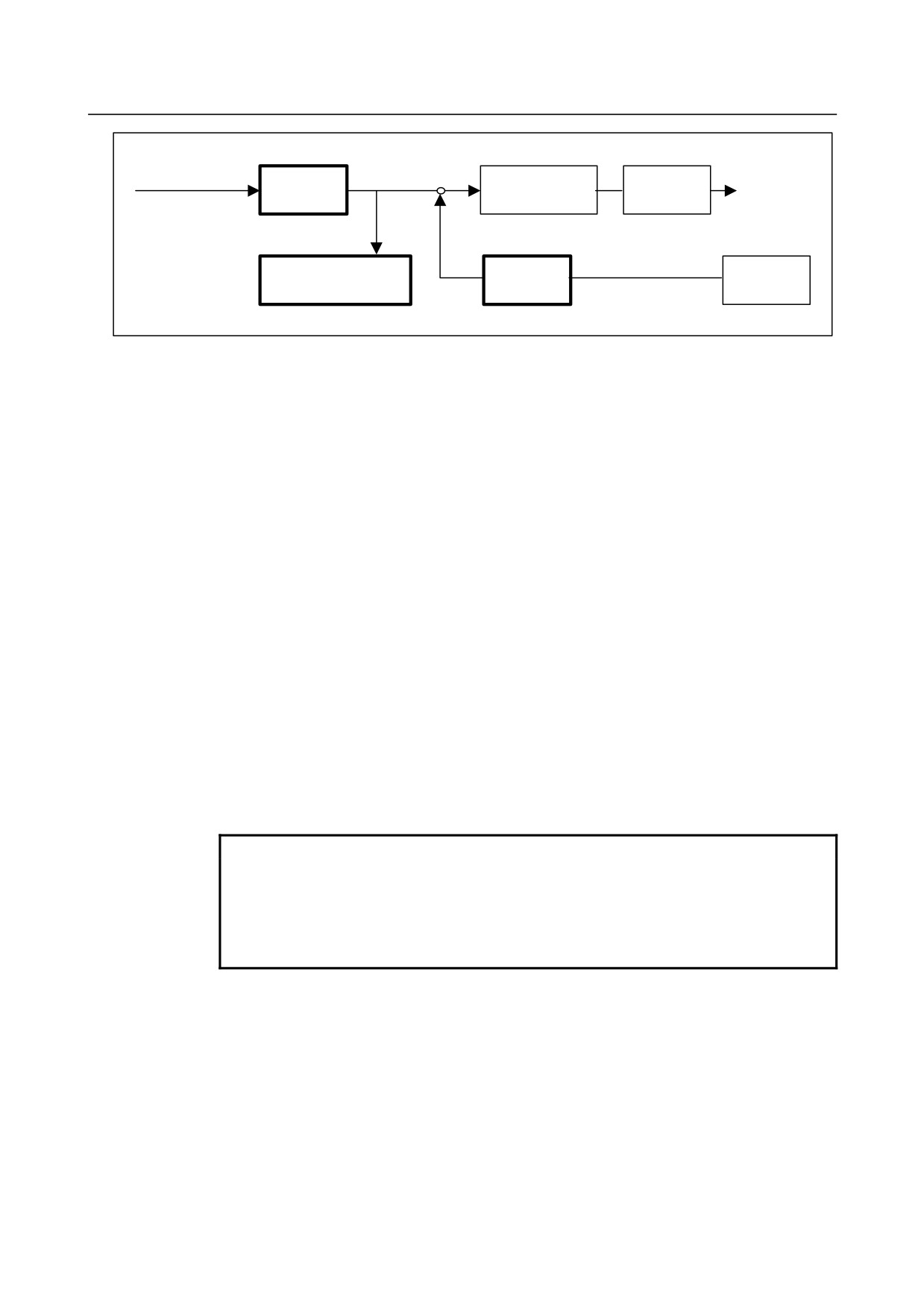
Set CMR and DMR so that the pulse weight of + input (command from the CNC) into the
error counter matches the pulse weight of -input (feedback from the position detector).
[Least command increment]/CMR=[Detection unit]=
[Feedback pulse unit]/DMR
[Least command increment]:
Minimum unit of commands issued from the CNC to the machine
[Detection unit]: Minimum unit for machine position detection
The unit of feedback pulses varies, depending on the type of detector.
[Feedback pulse unit]=[Amount of travel per rotation of the pulse coder]/[Number of
pulses per rotation of the pulse coder]
As the size of the reference counter, specify the grid interval for the reference position
return in the grid method.
[Size of the reference counter]=[Grid interval]/[Detection unit]
[Grid interval]=[Amount of travel per rotation of the pulse coder]
The setting of a command multiplier is as follows:
(1) When command multiplier is 1 to 1/27
Set value = 1 / command multiplier + 100
Valid data range : 101 to 127
(2) When command multiply is 0.5 to 48
Set value = 2 × command multiplier
Valid data range : 1 to 96
NOTE
1 If a feedrate exceeding the feedrate found by the expression below
is used, an incorrect travel amount may result or a servo alarm may
be issued. Be sure to use a feedrate not exceeding the feedrate
found by the following expression:
Fmax[mm/min] = 196602 × 104 × least command increment / CMR
- 93 -
4.DESCRIPTION OF PARAMETERS
B-64310EN/02
NOTE
2 For the FS0i-C, one of the following changes is required besides
setting bit 3 (DIAx) of parameter No. 1006 so that the axis based
on diameter specification achieves the specified amount of
movement.
• Halve the command multiplication (the detection unit is not
changed).
• Halve the detection unit and double the flexible feed gear
(DMR).
For the FS0i-D, only if bit 3 (DIAx) of parameter No. 1006 is set,
the CNC halves the specified pulse. Accordingly, the above
changes are not required (when the detection unit is not changed).
To halve the detection unit, double both CMR and DMR.
1821
Reference counter size for each axis
NOTE
When this parameter is set, the power must be turned off before
operation is continued.
[Input type] Parameter input
[Data type] 2-word axis
[Unit of data] Detection unit
[Valid data range] 0 to 999999999
Set a reference counter size.
As a reference counter size, specify a grid interval for reference position return based on
the grid method.
When a value less than 0 is set, the specification of 10000 is assumed.
When a linear scale with absolute address reference marks is used, set the interval of
mark 1.
1825
Servo loop gain for each axis
[Input type] Parameter input
[Data type] Word axis
[Unit of data] 0.01/sec
[Valid data range] 1 to 9999
Set the loop gain for position control for each axis.
When the machine performs linear and circular interpolation (cutting), the same value
must be set for all axes. When the machine requires positioning only, the values set for
the axes may differ from one another. As the loop gain increases, the response by position
control is improved. A too large loop gain, however, makes the servo system unstable.
The relationship between the positioning deviation (the number of pulses counted by the
error counter) and the feedrate is expressed as follows:
Positioning deviation = Feedrate / (60 × Loop gain)
Unit : Positioning deviation mm, inch or deg
Feedrate mm/min, inch/min, or deg/min
Loop gain
1/sec
1826
In-position width for each axis
[Input type] Parameter input
- 94 -

B-64310EN/02
4.DESCRIPTION OF PARAMETERS
[Data type] 2-word axis
[Unit of data] Detection unit
[Valid data range] 0 to 99999999
The in-position width is set for each axis.
When the deviation of the machine position from the specified position (the absolute
value of the positioning deviation) is smaller than the in-position width, the machine is
assumed to have reached the specified position. (The machine is in the in-position state.)
1827
In-position width in cutting feed for each axis
[Input type] Parameter input
[Data type] 2-word axis
[Unit of data] Detection unit
[Valid data range] 0 to 99999999
Set an in-position width for each axis in cutting feed. This parameter is used when bit 4
(CCI) of parameter No.1801=1.
1828
Positioning deviation limit for each axis in movement
[Input type] Parameter input
[Data type] 2-word axis
[Unit of data] Detection unit
[Valid data range] 0 to 99999999
Set the positioning deviation limit in movement for each axis.
If the positioning deviation exceeds the positioning deviation limit during movement, a
servo alarm
(SV0411) is generated, and operation is stopped immediately
(as in
emergency stop).
Generally, set the positioning deviation for rapid traverse plus some margin in this
parameter.
1829
Positioning deviation limit for each axis in the stopped state
[Input type] Parameter input
[Data type] 2-word axis
[Unit of data] Detection unit
[Valid data range] 0 to 99999999
Set the positioning deviation limit in the stopped state for each axis.
If, in the stopped state, the positioning deviation exceeds the positioning deviation limit
set for stopped state, a servo alarm (SV0410) is generated, and operation is stopped
immediately (as in emergency stop).
1830
Axis-by-axis positional deviation limit at servo-off time
[Input type] Parameter input
[Data type] 2-word axis
[Unit of data] Detection unit
[Valid data range] 0 to 99999999
This parameter is used to set a positional deviation limit at servo-off time, on an
axis-by-axis basis.
If the value specified with this parameter is exceeded at servo-off time, a servo alarm is
issued to cause an immediate stop (same as an emergency stop). Usually, set the same
value as a positional deviation at stop time.
- 95 -
4.DESCRIPTION OF PARAMETERS
B-64310EN/02
NOTE
When this parameter is set to 0, no positional deviation limit check
is made at servo-off time.
1836
Servo error amount where reference position return is possible
[Input type] Parameter input
[Data type] Word axis
[Unit of data] Detection unit
[Valid data range] 0 to 32767
This parameter sets a servo error used to enable reference position return.
In general, set this parameter to 0. (When 0 is set, 128 is assumed as the default.)
If, during reference position return, such a feedrate as exceeding a set value is not reached
even once before the limit switch for deceleration is released (the deceleration signal
(*DEC) is set to 1 again), the alarm (PS0090) "REFERENCE POSITION RETURN
FAILURE" is issued.
If, during reference position return, such a feedrate as exceeding a set servo error amount
is not reached even once before the limit switch for deceleration is released
(the
deceleration signal is set to 1 again), the alarm (PS0090) "REFERENCE POSITION
RETURN FAILURE" is issued.
NOTE
When bit 0 (PLC0) of parameter No. 2000 is 1, a check is
performed with a value 10 times as large as the parameter setting.
(Example)
When bit 0 (PLC0) of parameter No. 2000 is 1 and the setting is
10, if the number of servo errors is 100 or more, a reference
position return is enabled.
Distance to the first grid point when the reference position shift amount in the reference position shift
1844
function is 0 or when a reference position return is made by grid shift
NOTE
When this parameter is set, the power must be turned off before
operation is continued.
[Input type] Parameter input
[Data type] 2-word axis
[Unit of data] Detection unit
[Valid data range] -999999999 to 999999999
(1) When the reference position shift function is enabled
(when bit 4 (SFDx) of
parameter No. 1008 is set to 1)
Set the distance (detection unit) to the first grid point from a point at which the
deceleration dog is released when the reference position shift (parameter No. 1850)
is set to 0.
(2) When a reference position return is made by grid shift with a setting not to use
reference position setting without dogs (when bit 4 (SFDx) of parameter No. 1008 is
set to 0, and bit 1 (DLZx) of parameter No. 1005 is set to 0)
Set the distance to the first grid point from a point at which the deceleration dog is
released. (Detection unit)
(3) When a reference position return is made by grid shift with a setting to use reference
position setting without dogs (when bit 4 (SFDx) of parameter No. 1008 is set to 0,
and bit 1 (DLZx) of parameter No. 1005 is set to 1)
- 96 -
B-64310EN/02
4.DESCRIPTION OF PARAMETERS
Set the distance from the start position for reference position setting without dogs to
the first grid point. (Detection unit)
NOTE
1 When the reference position shift function is enabled (when bit 4
(SFDx) of parameter No. 1008 is set to 1)
When bit 4 (SFDx) of parameter No. 1008 is set to 1, the distance
from a point at which the deceleration dog is released to the first
grid point (parameter No. 1844) is set to 0, and reference position
shift (parameter No. 1850) is set to 0, a manual reference position
return allows this parameter to be set automatically. Do not change
an automatically set value.
2 When a reference position return is made by grid shift with a setting
not to use reference position setting without dogs (when bit 4
(SFDx) of parameter No. 1008 is set to 0, and bit 1 (DLZx) of
parameter No. 1005 is set to 0)
When a manual reference position return using deceleration dogs
is made, this parameter is set automatically.
3 When a reference position return is made by grid shift with a setting
to use reference position setting without dogs (when bit 4 (SFDx) of
parameter No. 1008 is set to 0, and bit 1 (DLZx) of parameter No.
1005 is set to 1)
When a reference position setting without dogs is made, this
parameter is set automatically.
1846
Distance for starting the second stage of smooth backlash compensation
[Input type] Parameter input
[Data type] 2-word axis
[Unit of data] Detection unit
[Valid data range] 0 to 999999999
For each axis, set the distance from the point where the axis movement direction is
reversed to the point where the second stage of smooth backlash compensation is started.
Smooth backlash compensation is disabled unless the following conditions are satisfied.
Setting of parameter No. 1846 ≥ 0
Setting of parameter No. 1846 < Setting of parameter No. 1847
1847
Distance for ending the second stage of smooth backlash compensation
[Input type] Parameter input
[Data type] 2-word axis
[Unit of data] Detection unit
[Valid data range] 0 to 999999999
For each axis, set the distance from the point where the axis movement direction is
reversed to the point where the second stage of smooth backlash compensation is ended.
Smooth backlash compensation is disabled unless the following conditions are satisfied.
Setting of parameter No. 1846 ≥ 0
Setting of parameter No. 1846 < Setting of parameter No. 1847
- 97 -
4.DESCRIPTION OF PARAMETERS
B-64310EN/02
1848
Value of the first stage of smooth backlash compensation
[Input type] Parameter input
[Data type] Word axis
[Unit of data] Detection unit
[Valid data range] -9999 to 9999
Set the value of the first stage of smooth backlash compensation for each axis.
If the setting of this parameter is greater than the total amount of backlash compensation,
smooth backlash compensation is not performed.
If the backlash compensating value
(No.
1851) for each axis is negative, set this
parameter to a negative value. If the sign of the backlash compensating value (No.
1851) for each axis is different, perform compensation with the value of the first stage of
smooth backlash compensation assumed to be 0.
1850
Grid shift and reference position shift for each axis
NOTE
When this parameter is set, the power must be turned off before
operation is continued.
[Input type] Parameter input
[Data type] 2-word axis
[Unit of data] Detection unit
[Valid data range] -99999999 to 99999999
To shift the reference position, the grid can be shifted by the amount set in this parameter.
Up to the maximum value counted by the reference counter can be specified as the grid
shift.
In case of parameter SFDx(No.1008#4) is 0: Grid shift
In case of parameter SFDx(No.1008#4) is 1: Reference point shift
NOTE
For setting the reference position without dogs, only the grid shift
function can be used.
(The reference position shift function cannot be used.)
1851
Backlash compensating value for each axis
[Input type] Parameter input
[Data type] Word axis
[Unit of data] Detection unit
[Valid data range] -9999 to 9999
Set the backlash compensating value for each axis.
When the machine moves in a direction opposite to the reference position return direction
after the power is turned on, the first backlash compensation is performed.
1852
Backlash compensating value used for rapid traverse for each axis
[Input type] Parameter input
[Data type] Word axis
[Unit of data] Detection unit
[Valid data range] -9999 to 9999
- 98 -
B-64310EN/02
4.DESCRIPTION OF PARAMETERS
Set the backlash compensating value used in rapid traverse for each axis. (This parameter
is valid when RBK, #4 of parameter 1800, is set to 1.) More precise machining can be
performed by changing the backlash compensating value depending on the feedrate, the
cutting feed or the rapid traverse positioning. Let the measured backlash at cutting feed be
A and the measured backlash at rapid traverse be B. The backlash compensating value is
shown below depending on the change of feedrate (cutting feed or rapid traverse) and the
change of the direction of movement.
Change of feedrate
Cutting feed to
Rapid traverse
Rapid
Cutting feed
Change of
cutting feed
to rapid
traverse to
to rapid
direction of movement
traverse
cutting feed
traverse
Same direction
0
0
±α
±(-α)
Opposite direction
±A
±B
±(B+α)
±(B+α)
NOTE
1 α=(A-B)/2
2 The positive or negative direction for compensating values is the
direction of movement.
NOTE
1 Jog feed is regarded as cutting feed.
2 The backlash compensation depending on a rapid traverse and a
cutting feed is not performed until the first reference position
return is completed after the power is turned on. The normal
backlash compensation is performed according to the value
specified in parameter No.1851 irrespective of a rapid traverse
and a cutting feed.
3 The backlash compensation depending on a rapid traverse and a
cutting feed is performed only when bit 4 (RBK) of parameter
No.1800 is set to 1. When RBK is set to 0, the normal backlash is
performed.
1868
Threshold position for converting scale data (each axis)
[Input type] Parameter input
[Data type] Real axis
[Unit of data] degree (machine unit)
[Min. unit of data] Depend on the increment system of the applied axis
[Valid data range] 0 or positive 9 digit of minimum unit of data (Refer to the standard parameter setting
table (B))
(When the increment system is IS-B, 0.0 to ++999999.999)
In the case that scale data of a rotary scale without rotary data is larger than the scale data
of the threshold position (this parameter value), it is converted to be continuous data in
movable range by subtracting one rotary data. The position out of movable range (angle
from an uncontinuous point) must be set as threshold position. As for the axis with this
parameter is set to 0, conversion of scale data is not performed.
NOTE
1 When this parameter is set, the power must be turned off before
operation is continued.
- 99 -

4.DESCRIPTION OF PARAMETERS
B-64310EN/02
NOTE
2 This parameter is available for only the rotary axis B type with an
absolute position detector (absolute pulse coder) or a rotary scale
with distance-coded reference marks (serial), as for the parameter
SCRx(No.1817#3) is set to 1.
3 This function cannot be used for distance coded rotary scale
interface (phase A/B).
4 Don't set this parameter in the case of no uncontinuous point within
movable range of rotary axis even if the rotary axis B type.
5 When this parameter is set, machine position and position on
absolute position detector become uncorresponding.
Consequently, the parameter APZ (No. 1815#4: indicating that the
correspondence is established) is set to 0, alarm DS0300. Why the
parameter APZ (No. 1815#4) is set to 0 can be checked using
diagnostic data No. 310#0.
1869
The amount of one rotation of rotary axis B type (each axis)
[Input type] Parameter input
[Data type] Real axis
[Unit of data] degree (machine unit)
[Min. unit of data] Depend on the increment system of the applied axis
[Valid data range] 0 or positive 9 digit of minimum unit of data (Refer to the standard parameter setting
table (B))
(When the increment system is IS-B, 0.0 to ++999999.999)
Normally, the amount of one rotation of rotary axis is 360, and the machine position 0 is
the reference position.
In this case, this parameter is set to 0.
For instance, when this parameter is set to 523.000, the amount of one rotation become
523.000 (in the case of IS-B), if it is necessary to set it arbitrarily.
NOTE
1 When this parameter is set, the power must be turned off before
operation is continued.
2 This parameter is available for only the rotary axis B type with an
absolute position detector (absolute pulse coder) or a rotary scale
with distance-coded reference marks (serial), as for the parameter
SCRx(No.1817#3) is set to 1 or the parameter SCRx(No.1815#0) is
set to 1.
3 In the case that the amount of one rotation of rotary axis is 360, this
parameter is set to 0.If it is necessary to set an amount of one
rotation of rotary axis arbitrarily, this parameter is set to the amount
of one rotation.
4 When this parameter is set, machine position and position on
absolute position detector become uncorresponding.
Consequently, the parameter APZ (No. 1815#4: indicating that the
correspondence is established) is set to 0, alarm DS0300. Why the
parameter APZ (No. 1815#4) is set to 0 can be checked using
diagnostic data No. 310#0.
- 100 -
B-64310EN/02
4.DESCRIPTION OF PARAMETERS
NOTE
5 This parameter No.1869 is common in movable range that is under
one rotation (the parameter SCRx (No.1817#3) is set to 1) and
movable range that is over one rotation (the parameter RVS
(No.1815#0) is set to 1).
1874
Numerator of the flexible feed gear for the built-in position detector
1875
Denominator of the flexible feed gear for the built-in position detector
NOTE
When these parameters are set, the power must be turned off before
operation is continued.
[Input type] Parameter input
[Data type] Word axis
[Valid data range] 1 to 32767
When using temporary absolute coordinate setting, set the flexible feed gear for the
built-in position detector on each axis. The settings are as follows:
No.1874
Number of position feedback pulses per motor revolution
=
No.1875
1,000,000
1880
Abnormal load detection alarm timer
[Input type] Parameter input
[Data type] Word path
[Unit of data] msec
[Valid data range] 0 to 32767
This parameter sets the time from the detection of an abnormal load until a servo alarm is
issued.
When 0 is set, however, the specification of 200 msec is assumed.
1881
Group number when an abnormal load is detected
[Input type] Parameter input
[Data type] Byte axis
[Valid data range] 0 to Number of controlled axes
Set the group number on each axis when an abnormal load is detected.
When an abnormal load is detected on an axis, only the movements on those axes that
belong to the same group as the axis are stopped.
If 0 is set for an axis, the movement on the axis is stopped when an abnormal load is
detected on any other axis.
This parameter is valid when bit 5 (ANA) of parameter No. 1804 is set to 1.
[Example] When the settings indicated below are made, and an abnormal load is detected on the 3rd
axis, the movements on the 1st axis, 2nd axis, 3rd axis, and 4th axis are stopped. When an
abnormal load is detected on the 4th axis, the movements on the 2nd axis and the 4th axis
are stopped.
- 101 -
4.DESCRIPTION OF PARAMETERS
B-64310EN/02
Parameter No. 1881
Setting value
(1st axis)
1
(2nd axis)
0
(3rd axis)
1
(4th axis)
0
(5th axis)
2
1882
Interval of mark 2 of a linear scale with absolute address reference marks
NOTE
When this parameter is set, the power must be turned off before
operation is continued.
[Input type] Parameter input
[Data type] 2-word axis
[Unit of data] Detection unit
[Valid data range] 0 to 999999999
Set the interval of mark 2 of a linear scale with absolute address reference marks.
Distance 1 from the scale zero point to reference position (linear scale with absolute address reference
1883
marks) or distance 1 from the base point to reference position (linear scale with an absolute address
zero point)
NOTE
When this parameter is set, the power must be turned off before
operation is continued.
[Input type] Parameter input
[Data type] 2-word axis
[Unit of data] Detection unit
[Valid data range] -999999999 to 999999999
Distance 2 from the scale zero point to reference position (linear scale with absolute address reference
1884
marks) or distance 2 from the base point to reference position (linear scale with an absolute address
zero point)
NOTE
When this parameter is set, the power must be turned off before
operation is continued.
[Input type] Parameter input
[Data type] 2-word axis
[Unit of data] Detection unit
[Valid data range] -999 to 999
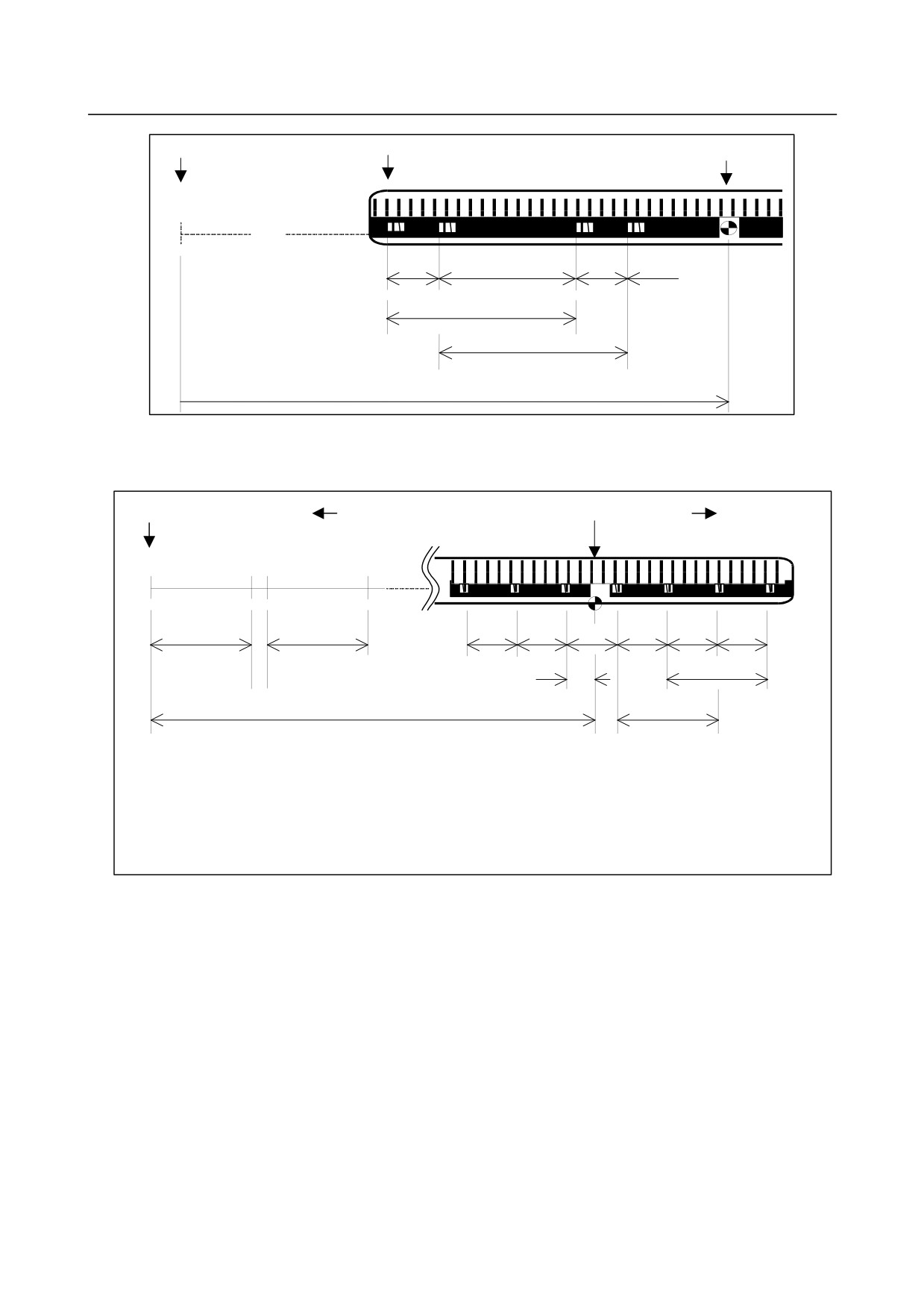
When a linear scale with absolute address reference marks is used, set the distance from
the scale zero point to reference position in parameter Nos. 1883 and 1884).
Distance from the zero point to the reference position of a linear scale
= No. 1884 × 1,000,000,000 + No. 1883
The scale zero point represents a point where mark 1 and mark 2 match. Usually, this
point is a virtual point that does not physically exist on the scale. (See the figure below.)
If the reference position is placed in the + direction when viewed from the scale zero
point, set a positive value. If the reference position is placed in the - direction when
viewed from the scale zero point, set a negative value.
- 102 -
B-64310EN/02
4.DESCRIPTION OF PARAMETERS
Zero point of encoder
Encoder end
Reference position
Mark 1 Mark 2
Mark 1 Mark 2
Mark 1 = mark 2
・・・・
8.0
42.0
8.2
41.8
Parameter No.1821
Parameter No.1882
Parameter No.1884) × 1,000,000,000 + Parameter No.1883
[Example of parameter settings]
When an encoder as shown below is used with an IS-B, millimeter machine:
Scale zero point
+ direction
Reference position
- direction
A
B
Mark 1 Mark 2
Mark 1
Mark 2 Mark 1 Mark 2 Mark 1
Mark 1 = mark 2
Mark 1 Mark 2
Mark 1
9.940
10.060
9.960
10.040
9.980
10.020
20.00
19.980
0
5.000
20.000mm
-[9960/(20020-20000)*20000+5000] = -9965000
20.020mm
Parameters No.1821 (interval of mark 1)
=
20000
No.1882 (interval of mark 2)
=
20020
No.1883 (reference position)
=
position of point A + 5.000
=
distance between A and B/(mark 2 - mark 1) × mark 1+ 5000
=
9960/ (20020 - 20000) × 20000+5000
=
9965000
=
-9965000 (the reference position is on the negative side)
[Setting parameter No. 1883]
When it is difficult to measure the distance from the scale zero point to the reference
position (parameter No. 1883), the method described below can be used to find the
distance.
<1> Set parameter No. 1815 to enable this function.
Set an appropriate value in parameter No. 1821 and No. 1882.
Set 0 in parameter No. 1240.
Set 0 in parameter No. 1883 and No. 1884.
<2> At an appropriate position, establish a reference position.
(As a result, the machine coordinate represents the distance from the scale zero point
to the current position.)
<3> By jog feed or handle feed, place the machine at the accurate reference position.
<4> In parameter No. 1883, set the machine coordinate of that time converted to the
detection unit (machine coordinate × CMR).
<5> If necessary, set parameter No. 1240.
- 103 -
4.DESCRIPTION OF PARAMETERS
B-64310EN/02
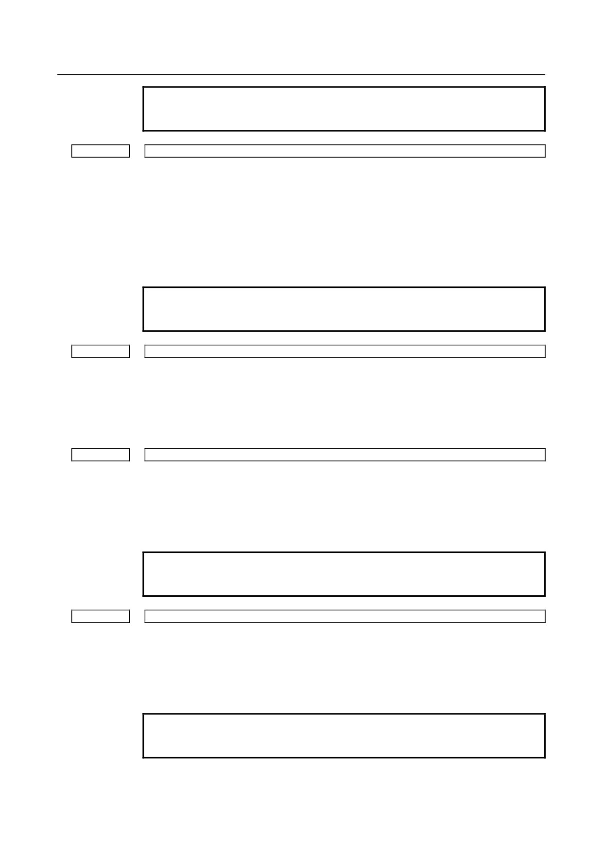
When a linear scale with an absolute address zero point is used, set the distance from the
base point to the reference position in parameter Nos. 1883 and 1884. The base point is a
point at a scale end as shown below.
Base point
Reference position
Mark 1 Mark 2
Mark 1
Mark 2
Mark 1
Mark 2 Mark 1
10.020
9.980
10.040
9.960
10.060
9.940
20.000
20.020
If the reference position is located in the positive direction when viewed from the base
point, set a positive value; if the reference position is located in the negative
direction, set a negative value. Set the value by following the steps explained below.
<1> Set bit 1 (OPT) of parameter No. 1815 , bit 2 (DCL) of parameter No. 1815, and bit
3 (SDC) of parameter No. 1818 to enable this function.
Set 0 in parameter No. 1240.
Set 0 in parameter No. 1883 and No. 1884.
<2> At an appropriate position, establish a reference position.
(Consequently, the machine coordinate value indicates the distance from the base
point to current position.)
<3> By jog feed or handle feed, place the machine at the accurate reference position.
<4> In parameters Nos. 1883 and 1884, set the machine coordinate of that time converted
to the detection unit (machine coordinate × CMR).
If necessary, set parameter No. 1240.
NOTE
1 Set parameter Nos. 1883 and 1884 so that the distance from the
scale zero point (for a linear scale with absolute address reference
marks) or the base point (for a linear scale with an absolute
address zero point) to the reference position is within the range
from -999,999,999,999 to +999,999,999,999. If a value beyond this
range is set, an alarm (PS 5325) is issued.
2 The scale area on the scale cannot be extended across the scale
zero point or base point. Make parameter settings not to cause the
scale area to extend beyond the scale zero point or base point.
1885
Maximum allowable value for total travel during torque control
[Input type] Parameter input
[Data type] Word axis
[Unit of data] Detection unit
[Valid data range] 0 to 32767
For the axis subjected to be torque control by the axis control command of the PCM axis
control function, set the maximum allowable value of the total travel value (error counter
value) during torque control. If the movement integration value exceeds this setting
during torque control, a servo alarm (SV0423) occurs.
- 104 -
B-64310EN/02
4.DESCRIPTION OF PARAMETERS
NOTE
This parameter is enabled when the parameter TQF (bit 4 of
No.1803) is 0 (follow-up is not performed during torque control).
1886
Positional deviation when torque control is canceled
[Input type] Parameter input
[Data type] Word axis
[Unit of data] Detection unit
[Valid data range] 1 to 32767
For the axis subjected to be torque control by the axis control command of the PCM axis
control function, set the positional deviation below which torque control is canceled and
switching to positional control is performed. If the positional deviation is equal to or
less than the setting of this parameter, switching to positional control is performed.
NOTE
This parameter is enabled when the parameter TQF (bit 4 of
No.1803) is 0 (follow-up is not performed during torque control).
1895
Servo motor axis number used for a milling tool
[Input type] Parameter input
[Data type] Byte path
[Valid data range] 1 to number of controlled axes
This parameter sets the servo motor axis number used for displaying the speed of a
milling tool that incorporates a servo motor.
1898
Number of gear teeth on the servo motor axis side
[Input type] Parameter input
[Data type] Word axis
[Valid data range] 1 to 9999
This parameter sets the number of servo motor axis gear teeth used for displaying the
speed of a milling tool that incorporates a servo motor.
NOTE
This parameter is valid when a non-zero value is set in parameter
No. 1895.
1899
Number of gear teeth on the milling axis side
[Input type] Parameter input
[Data type] Word axis
[Valid data range] 1 to 9999
This parameter sets the number of milling axis gear teeth used for displaying the speed of
a milling tool that incorporates a servo motor.
NOTE
This parameter is valid when a non-zero value is set in parameter
No. 1895.
- 105 -
4.DESCRIPTION OF PARAMETERS
B-64310EN/02
#7
#6
#5
#4
#3
#2
#1
#0
1902
ASE
FMD
[Input type] Parameter input
[Data type] Bit
NOTE
When at least one of these parameters is set, the power must be
turned off before operation is continued.
#0 FMD The FSSB setting mode is:
0: Automatic setting mode.
(When bit 0 (DFS) of parameter No. 14476 is 0:
If the relationship between the axis and the amplifier and the like are defined on the
FSSB setting screen, parameters No. 1023, No. 1905, Nos. 1936 and 1937, Nos.
14340 to 14357, and Nos. 14376 to 14391 are automatically set.)
(When bit 0 (DFS) of parameter No. 14476 is 1:
If the relationship between the axis and the amplifier and the like are defined on the
FSSB setting screen, parameters No. 1023, No. 1905, Nos. 1910 to 1919, and Nos.
1936 and 1937 are automatically set.)
1: Manual setting 2 mode.
(When bit 0 (DFS) of parameter No. 14476 is 0:
Manually set parameters No.1023, No.1905, Nos.1936 and 1937, Nos.14340 to
14357, and Nos.14376 to 14391.)
(When bit 0 (DFS) of parameter No. 14476 is 1:
Manually set parameters No.1023, No.1905, Nos.1910 to 1919, and Nos. 1936 and
1937.)
#1 ASE When automatic setting mode is selected for FSSB setting (when the FMD parameter (bit
0 of parameter No.1902) is set to 0), automatic setting is:
0: Not completed.
1: Completed.
This bit is automatically set to 1 upon the completion of automatic setting.
#7
#6
#5
#4
#3
#2
#1
#0
1905
PM2x
PM1x
FSLx
[Input type] Parameter input
[Data type] Bit axis
NOTE
When at least one of these parameters is set, the power must be
turned off before operation is continued.
#0 FSLx The type of interface used between the servo amplifier and servo software is:
0 : Fast type.
1 : Slow type.
The user can choose between two interface types for servo data transfer: fast type or slow
type. Set this parameter so that the following conditions are satisfied:
• When a one-axis amplifier is used, either the fast type or slow type interface can be
used.
• When a two-axis amplifier is used, the use of the fast type for both axes is not
allowed. The slow type can be used for both axes.
- 106 -
B-64310EN/02
4.DESCRIPTION OF PARAMETERS
• When a three-axis amplifier is used, the requirement for a two-axes amplifier
described above applies to the first and second axes, and the requirement for a
one-axis amplifier, again described above, applies to the third axis.
• When an odd number is specified for parameter No.1023, the fast type interface
must be used. However, the slow type may be used for high-speed current loop axis
and high-speed interface axis.
• When an even number is specified for parameter No.1023, only the slow type
interface can be used. (The FSL bit must always be set to 1.)
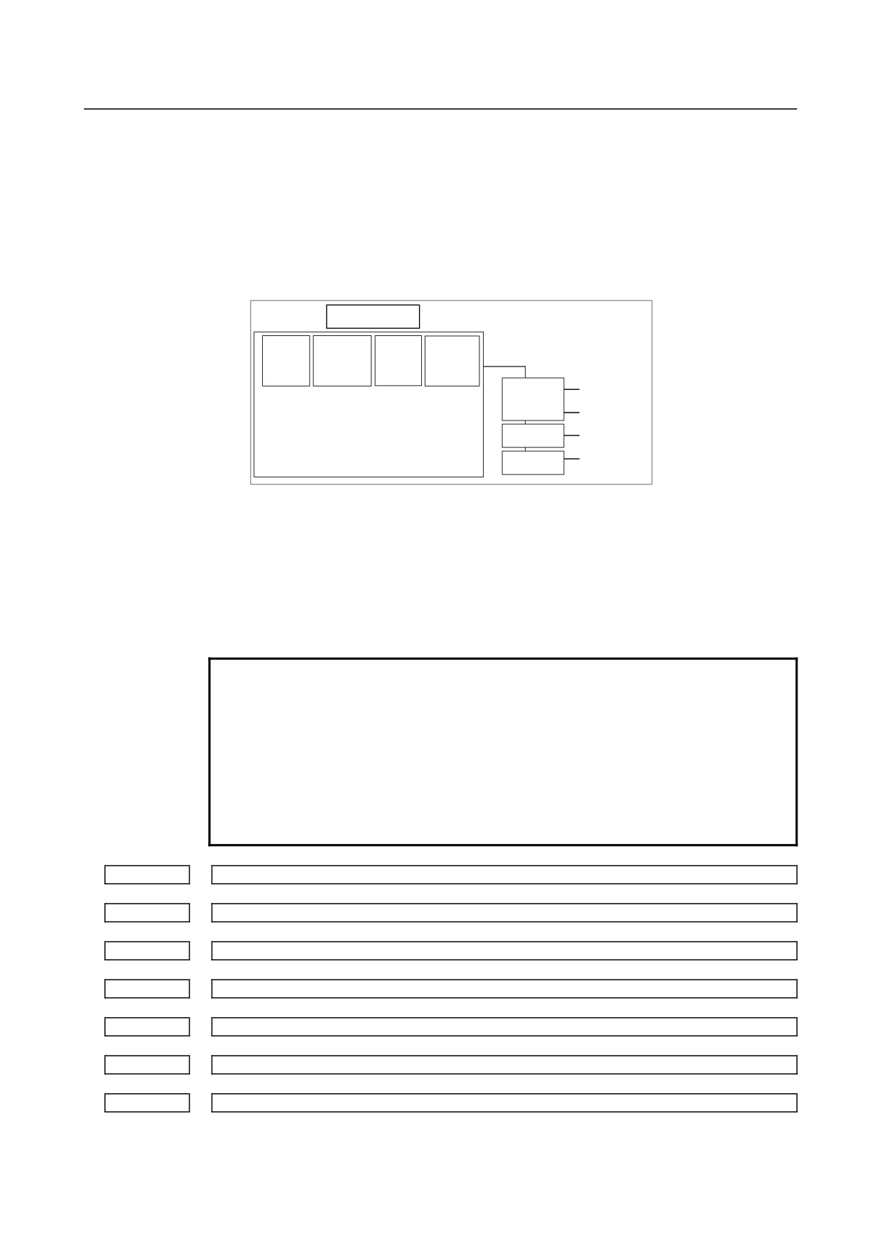
CNC
Controlled
Program
Servo axis
I/F type
number
axis
axis name
Fast/Slow
(No. 1023)
number
(No. 1020)
Two-axis
X (Fast)
1
X
1
F
amplifier
A (Slow)
2
Y
3
F
Single-axis
Y (Fast)
3
Z
4
S
amplifier
Single-axis
Z (Slow)
4
A
2
S
amplifier
#6
PM1x The first separate detector interface unit is:
0: Not used.
1: Used.
#7
PM2x The second separate detector interface unit is:
0: Not used.
1: Used.
NOTE
When automatic setting mode is selected for FSSB setting (when
the parameter FMD (No.1902#0) is set to 0), this parameter is
automatically set when input is performed with the FSSB setting
screen. When manual setting 2 mode is selected for FSSB setting
(when the parameter FMD (No.1902#0) is set to 1), this parameter
must be set directly. When a separate detector interface unit is
used, a connector number must be set in the corresponding
parameter (No.1936 or No.1937).
1910
Address conversion table value for slave 1 (ATR)
1911
Address conversion table value for slave 2 (ATR)
1912
Address conversion table value for slave 3 (ATR)
1913
Address conversion table value for slave 4 (ATR)
1914
Address conversion table value for slave 5 (ATR)
1915
Address conversion table value for slave 6 (ATR)
1916
Address conversion table value for slave 7 (ATR)
- 107 -

4.DESCRIPTION OF PARAMETERS
B-64310EN/02
1917
Address conversion table value for slave 8 (ATR)
1918
Address conversion table value for slave 9 (ATR)
1919
Address conversion table value for slave 10 (ATR)
NOTE
When these parameters are set, the power must be turned off
before operation is continued.
[Input type] Byte
[Valid data range] 0 to 3, 16, 40, 48
These parameters set address conversion table values for slaves 1 to 10.
A slave is the generic name given to a device such as a servo amplifier or separate
detector interface unit, connected to the CNC via an FSSB optical cable. Smaller numbers,
starting from 1 are assigned to slaves closer to the CNC; the maximum number that can
be assigned is 10. A two-axis amplifier has two slaves, while a three-axis amplifier has
three slaves. Set each parameter as described below, depending on whether the slave is an
amplifier or separate detector interface unit, or when no slave exists.
• When the slave is an amplifier:
Set the value obtained by subtracting 1 from the setting of parameter No.1023 for
the axis to which the amplifier is assigned.
• When the slave is a separate detector interface unit:
Set 16 for the first separate detector interface unit (closest to the CNC).
Set 48 for the second separate detector interface unit (furthest from the CNC).
• When no slave exists
Set 40.
NOTE
1 When using the simple electric gear box (EGB) function
The EGB axis (axis set with parameter No.7771) does not actually
require an amplifier. So, assume that the EGB axis is connected to
a dummy amplifier. Accordingly, as the address conversion table
value for a nonexistent slave, set the value obtained by subtracting
1 from the setting made for parameter No.1023 for the EGB axis,
instead of setting 40.
2 When automatic setting mode is selected for FSSB setting (when
bit 0 (FMD) of parameter No.1902 is set to 0), parameters No.1910
to No.1919 are automatically set when input is performed with the
FSSB setting screen. When manual setting 2 mode is selected for
FSSB setting (when bit 0 (FMD) of parameter No.1902 is set to 1),
parameter No.1910 to No.1919 must be directly set.
- 108 -
B-64310EN/02
4.DESCRIPTION OF PARAMETERS
• Examples of axis configurations and parameter settings
CNC
Controlled
Program
Servo axis
Slave
ATR
axis
axis name
number
number
No.1910
Axis
number
No.1020
No.1023
to 1919
1
X
1
2
Y
3
1-axis
3
Z
4
1
0
X
amplifier
4
A
2
2-axis
2
1
A
amplifier
3
2
Y
M1
4
16
(M1)
1-axis
5
3
Z
amplifier
6
48
(M2)
M2
7
40
(None)
8
40
(None)
9
40
(None)
10
40
(None)
CNC
Controlled
Program
Servo axis
Slave
ATR
axis
axis
number
number
No.1910
Axis
number
name
No.1023
to 1919
1
X
1
2
Y
3
1-axis
1
0
X
3
Z
4
amplifier
4
A
2
2-axis
2
2
Y
amplifier
3
3
Z
1-axis
4
1
A
amplifier
M1
5
16
(M1)
6
48
(M2)
M2
7
40
(None)
8
40
(None)
9
40
(None)
10
40
(None)
M1/M2: First separate detector interface unit/second separate detector interface unit
1936
Connector number of the first separate detector interface unit
1937
Connector number of the second separate detector interface unit
NOTE
When these parameters are set, the power must be turned off before
operation is continued.
[Input type] Parameter input
[Data type] Byte axis
[Valid data range] 0 to 7
- 109 -
4.DESCRIPTION OF PARAMETERS
B-64310EN/02
This parameter sets the connector number corresponding to the connector connected
when using the separator detector interface unit set by bits 6 and 7 of parameter No. 1905
minus 1. That is, set 0 to 7 for connector numbers 1 to 8, respectively. Set 0 for the
axis for which the separator detector interface unit is not used.
Use successive numbers for one separator detector interface unit. Do not omit a
intermediate number.
[Example]
Connector
Connector
number for the
number for the
PM2x, PM1x
Controlle
first separate
second separate
No.1936
No.1937
(No.1905#7,
d axis
detector interface
detector interface
#6)
unit
unit
X
1
Not used
0
0
0, 1
Y
Not used
2
0
1
1, 0
Z
Not used
1
0
0
1, 0
A
Not used
Not used
0
0
0, 0
NOTE
When automatic setting mode is selected for FSSB setting (when the
parameter FMD (No.1902#0) is set to 0), these parameters are
automatically set when input is performed with the FSSB setting
screen. When manual setting 2 mode is selected for FSSB setting
(when the parameter FMD (No.1902#0) is set to 1), these
parameters must be set directly.
Parameters No.2000 to 2999 are for digital servo, The following parameters are not explained in this
manual. Refer to FANUC AC SERVO MOTOR αi series PARAMETER MANUAL (B-65270EN)
No.
Data type
Contents
2000
Bit axis
PGEX
DGPR
PLC0
2001
Bit axis
AMR6
AMR5
AMR4
AMR3
AMR2
AMR1
AMR0
2002
Bit axis
PFSE
2003
Bit axis
VOFS
OVSC
BLEN
NPSP
PIEN
OBEN
TGAL
2004
Bit axis
TRW1
TRW0
TIB0
TIA0
2005
Bit axis
SFCM
BRKC
FEED
2006
Bit axis
FCBL
2007
Bit axis
FRCA
IGNV
ESP2
2008
Bit axis
LAXD
VFBA
TNDM
2009
Bit axis
BLST
BLCU
SERD
2010
Bit axis
POLE
HBBL
HBPE
BLTE
LINE
2011
Bit axis
RCCA
FFAL
EGB
2012
Bit axis
STNG
MSFE
2013
Bit axis
APTG
HRV3
2014
Bit axis
2015
Bit axis
BZNG
BLAT
SSG1
PGTW
2016
Bit axis
PK2VDN
ABNT
2017
Bit axis
PK2V25
HTNG
DBST
2018
Bit axis
PFBCPY
OVR8
MOVOBS
RVRSE
2019
Bit axis
DPFB
SLEN
INVSYS
LBUFEX
TANDMP
2020
Word axis
Motor number
2021
Word axis
Load inertia ratio
2022
Word axis
Direction of motor rotation
2023
Word axis
Number of velocity pulses
- 110 -

B-64310EN/02
4.DESCRIPTION OF PARAMETERS
No.
Data type
Contents
2024
Word axis
Number of position pulses
2028
Word axis
Position gain switching speed
2029
Word axis
Effective speed for integral acceleration at low speed
2030
Word axis
Effective speed for integral deceleration at low speed
2031
Word axis
Torque command difference threshold of torque difference alarm
2033
Word axis
Number of position feedback pulses for damping control
2034
Word axis
Damping control gain
2036
Word axis
Damping compensation gain
(main axis) and damping compensation
phase
coefficient
(sub-axis) for tandem control
2039
Word axis
Second-stage acceleration for two-stage backlash acceleration
2040
Word axis
Current loop integral gain (PK1)
2041
Word axis
Current loop proportional gain (PK2)
2042
Word axis
Current loop gain (PK3)
2043
Word axis
Velocity loop integral gain (PK1V)
2044
Word axis
Velocity loop proportional gain (PK2V)
2045
Word axis
Velocity loop incomplete integral gain (PK3V)
2046
Word axis
Velocity loop gain (PK4V)
2047
Word axis
Observer parameter (POA1)
2048
Word axis
Backlash acceleration
2049
Word axis
Maximum amplitude for dual position feedback
2050
Word axis
Observer parameter (POK1)
2051
Word axis
Observer parameter (POK2)
2053
Word axis
Current dead-band compensation (PPMAX)
2054
Word axis
Current dead-band compensation (PDDP)
2055
Word axis
Current dead-band compensation (PHYST)
2056
Word axis
Variable current gain during deceleration
2057
Word axis
Phase-D current at high speed
2058
Word axis
Phase-D current limit at high speed
2060
Word axis
Torque limit
2062
Word axis
Overload protection coefficient (OVC1)
2063
Word axis
Overload protection coefficient (OVC2)
2064
Word axis
Soft disconnection alarm level
2065
Word axis
Overload protection coefficient (OVCLMT)
2066
Word axis
Acceleration feedback gain
2067
Word axis
Torque command filter
2068
Word axis
Feed forward coefficient
2069
Word axis
Velocity feed forward coefficient
2070
Word axis
Backlash acceleration timing
2071
Word axis
Backlash acceleration effective duration, number
of times
static friction compensation
is
performed
2072
Word axis
Static friction compensation
2073
Word axis
Parameter for determining stop of static friction compensation
2074
Word axis
Current-dependent current loop gain
2077
Word axis
Overshoot compensation counter
2078
Word axis
Conversion coefficient for dual position feedback (numerator)
2079
Word axis
Conversion coefficient for dual position feedback (denominator)
2080
Word axis
First-order lag time constant for dual position feedback
2081
Word axis
Zero width for dual position feedback
2082
Word axis
Backlash acceleration stop amount
2083
Word axis
Brake control timer (ms)
2084
Word axis
Flexible feed gear (numerator)
2085
Word axis
Flexible feed gear (denominator)
2086
Word axis
Rated current parameter
2087
Word axis
Torque offset
2088
Word axis
Machine velocity feedback coefficient gain
- 111 -

4.DESCRIPTION OF PARAMETERS
B-64310EN/02
No.
Data type
Contents
2089
Word axis
Second-stage end magnification for two-stage backlash acceleration
2092
Word axis
Advanced preview feed forward coefficient
2094
Word axis
Single-direction backlash acceleration amount
2095
Word axis
Feed-forward timing adjustment coefficient
2097
Word axis
Static friction compensation stop parameter
2099
Word axis
N-pulse suppression level
2101
Word axis
Overshoot compensation effective level
2102
Word axis
Final clamp value for actual current limit
2103
Word axis
Amount of track back upon detection of unexpected disturbance torque
2104
Word axis
Unexpected disturbance torque detection alarm level (for cutting when switching is used)
2105
Word axis
Torque constant for torque control
2107
Word axis
Velocity loop gain override during cutting
2110
Word axis
Magnetic saturation compensation (base/coefficient)
2111
Word axis
Deceleration torque limit (base/coefficient)
2112
Word axis
AMR conversion coefficient 1
2113
Word axis
Resonance elimination filter 1 : Attenuation center frequency
2114
Word axis
Acceleration amount override for backlash acceleration
2116
Word axis
Unexpected disturbance torque detection, dynamic friction compensation value
2118
Word axis
Excessive error level between semi-closed and closed loops for dual position feedback
2119
Word axis
Stop level with variable proportional gain
2126
Word axis
Tandem control, time constant for switching position feedback
2127
Word axis
Non-interacting control coefficient
2128
Word axis
Weak magnetic flux compensation (coefficient)
2129
Word axis
Weak magnetic flux compensation (base/limit)
2130
Word axis
Two smooth compensations per magnetic pole pair
2131
Word axis
Four smooth compensations per magnetic pole pair
2132
Word axis
Six smooth compensations per magnetic pole pair
2133
Word axis
Deceleration phase delay compensation coefficient (PHDLY1)
2134
Word axis
Deceleration phase delay compensation coefficient (PHDLY2)
2137
Word axis
Stage 1 acceleration amount override for two-stage backlash acceleration
2138
Word axis
AMR conversion coefficient 2
2139
Word axis
AMR offset
2142
Word axis
Alarm level for detecting abnormal load during rapid traverse
2144
Word axis
Position feed forward coefficient for cutting
2145
Word axis
Velocity feed forward coefficient for cutting
2146
Word axis
Two-stage backlash acceleration end timer
2156
Word axis
Torque command filter (during rapid traverse)
2161
Word axis
OVC magnification at stop time (OVCSTP)
2162
Word axis
Second overload protection coefficient (POVC21)
2163
Word axis
Second overload protection coefficient (POVC22)
2164
Word axis
Second overload protection coefficient (POVCLMT2)
2165
Word axis
Maximum amplifier current
2167
Word axis
Stage 2 acceleration amount offset for two-stage backlash acceleration
2177
Word axis
Resonance elimination filter 1 : Attenuation band width
2179
Word axis
Reference counter capacity (denominator)
2185
Word axis
Position pulse conversion coefficient
2200
Bit axis
P2EX
ABGO
IQOB
OVSP
2201
Bit axis
CPEE
RNLV
CROF
2202
Bit axis
DUAL
OVS1
PIAL
VGCCR
2203
Bit axis
FRC2AX2
CRPI
2204
Bit axis
DBS2
PGTWN2
HSTP10
2205
Bit axis
HDIS
HD2O
FULDMY
2206
Bit axis
HBSF
2207
Bit axis
PK2D50
- 112 -