FANUC Series 0i-MODEL D, Series 0i Mate-MODEL D. PARAMETER MANUAL - page 3
B-64310EN/02
4.DESCRIPTION OF PARAMETERS
[Valid data range] 9 digit of minimum unit of data (refer to standard parameter setting table (A))
(When the increment system is IS-B, -999999.999 to +999999.999)
Set the coordinate value of stored stroke check 3 on each axis in the + or - direction in the
machine coordinate system.
NOTE
1 Specify diameter values for any axes for which diameter
programming is specified.
2 The area inside the area set by parameter No. 1324 and No. 1325
is a prohibited area.
1326
Coordinate value II of stored stroke check 1 in the positive direction on each axis
1327
Coordinate value II of stored stroke check 1 in the negative direction on each axis
[Input type] Parameter input
[Data type] Real axis
[Unit of data] mm, inch, degree (machine unit)
[Min. unit of data] Depend on the increment system of the applied axis
[Valid data range] 9 digit of minimum unit of data (refer to standard parameter setting table (A))
(When the increment system is IS-B, -999999.999 to +999999.999)
Set the coordinate value of stored stroke check 1 on each axis in the + or - direction in the
machine coordinate system.
When the stored stroke check switch signal EXLM is set to 1, or the stored stroke check
switch signal for each axis direction +EXLx is set to 1, parameter No. 1326 and No. 1327
are used for stroke check instead of parameter No.1320 and No. 1321.
NOTE
1 Specify diameter values for any axes for which diameter
programming is specified.
2 The area outside the area set by parameter No. 1326 and No. 1327
is a prohibited area.
3 The EXLM signal is valid only when bit 2 (LMS) of parameter No.
1300 is set to 1.
4 The +EXLx signal is valid only when bit 0 (DLM) of parameter No.
1301 is set to 1.
4.13 PARAMETERS OF THE CHUCK AND TAIL STOCK
BARRIER (T SERIES)
Profile of a chuck
1330
[Input type] Parameter input
[Data type] Byte path
[Valid data range] 0 to 1
Select a chuck figure.
0 : Chuck which holds a workpiece on the inner surface
1 : Chuck which holds a workpiece on the outer surface
- 53 -
4.DESCRIPTION OF PARAMETERS
B-64310EN/02
Dimensions of the claw of a chuck (L)
1331
[Input type] Parameter input
[Data type] Real path
[Unit of data] mm, inch (input unit)
[Min. unit of data] Depend on the increment system of the applied axis
[Valid data range] 0 or positive 9 digit of minimum unit of data (refer to the standard parameter setting table
(B))
(When the increment system is IS-B, 0.0 to +999999.999)
Set the length (L) of the claw of the chuck.
NOTE
Whether to specify this parameter by using a diameter value or
radius value depends on whether the corresponding axis is based
on diameter specification or radius specification.
Dimensions of the claw of a chuck (W)
1332
[Input type] Parameter input
[Data type] Real path
[Unit of data] mm, inch (input unit)
[Min. unit of data] Depend on the increment system of the applied axis
[Valid data range] 0 or positive 9 digit of minimum unit of data (refer to the standard parameter setting table
(B))
(When the increment system is IS-B, 0.0 to +999999.999)
Set the width (W) of the claw of the chuck.
NOTE
Specify this parameter by using a radius value at all times.
Dimensions of the claw of a chuck (L1)
1333
[Input type] Parameter input
[Data type] Real path
[Unit of data] mm, inch (input unit)
[Min. unit of data] Depend on the increment system of the applied axis
[Valid data range] 0 or positive 9 digit of minimum unit of data (refer to the standard parameter setting table
(B))
(When the increment system is IS-B, 0.0 to +999999.999)
Set the length (L1) of the claw of the chuck.
NOTE
Whether to specify this parameter by using a diameter value or
radius value depends on whether the corresponding axis is based
on diameter specification or radius specification.
Dimensions of the claw of a chuck (W1)
1334
[Input type] Parameter input
- 54 -
B-64310EN/02
4.DESCRIPTION OF PARAMETERS
[Data type] Real path
[Unit of data] mm, inch (input unit)
[Min. unit of data] Depend on the increment system of the applied axis
[Valid data range] 0 or positive 9 digit of minimum unit of data (refer to the standard parameter setting table
(B))
(When the increment system is IS-B, 0.0 to +999999.999)
Set the width (W1) of the claw of the chuck.
NOTE
Specify this parameter by using a radius value at all times.
X coordinate of a chuck (CX)
1335
[Input type] Parameter input
[Data type] Real path
[Unit of data] mm, inch (input unit)
[Min. unit of data] Depend on the increment system of the applied axis
[Valid data range] 9 digit of minimum unit of data (refer to standard parameter setting table (A))
(When the increment system is IS-B, -999999.999 to +999999.999)
Set the chuck position (X coordinate) in the workpiece coordinate system.
NOTE
Whether to specify this parameter by using a diameter value or
radius value depends on whether the corresponding axis is based
on diameter specification or radius specification.
Z coordinate of a chuck (CZ)
1336
[Input type] Parameter input
[Data type] Real path
[Unit of data] mm, inch (input unit)
[Min. unit of data] Depend on the increment system of the applied axis
[Valid data range] 9 digit of minimum unit of data (refer to standard parameter setting table (A))
(When the increment system is IS-B, -999999.999 to +999999.999)
Set the chuck position (Z coordinate) in the workpiece coordinate system.
NOTE
Whether to specify this parameter by using a diameter value or
radius value depends on whether the corresponding axis is based
on diameter specification or radius specification.
Length of a tail stock (L)
1341
[Input type] Parameter input
[Data type] Real path
[Unit of data] mm, inch (input unit)
[Min. unit of data] Depend on the increment system of the applied axis
[Valid data range] 0 or positive 9 digit of minimum unit of data (refer to the standard parameter setting table
(B))
(When the increment system is IS-B, 0.0 to +999999.999)
- 55 -
4.DESCRIPTION OF PARAMETERS
B-64310EN/02
Set the length (L) of the tail stock.
NOTE
Whether to specify this parameter by using a diameter value or
radius value depends on whether the corresponding axis is based
on diameter specification or radius specification.
Diameter of a tail stock (D)
1342
[Input type] Parameter input
[Data type] Real path
[Unit of data] mm, inch (input unit)
[Min. unit of data] Depend on the increment system of the applied axis
[Valid data range] 0 or positive 9 digit of minimum unit of data (refer to the standard parameter setting table
(B))
(When the increment system is IS-B, 0.0 to +999999.999)
Set the diameter (D) of the tail stock.
NOTE
Specify this parameter by using a diameter value at all times.
Length of a tail stock (L1)
1343
[Input type] Parameter input
[Data type] Real path
[Unit of data] mm, inch (input unit)
[Min. unit of data] Depend on the increment system of the applied axis
[Valid data range] 0 or positive 9 digit of minimum unit of data (refer to the standard parameter setting table
(B))
(When the increment system is IS-B, 0.0 to +999999.999)
Set the length (L1) of the tail stock.
NOTE
Whether to specify this parameter by using a diameter value or
radius value depends on whether the corresponding axis is based
on diameter specification or radius specification.
Diameter of a tail stock (D1)
1344
[Input type] Parameter input
[Data type] Real path
[Unit of data] mm, inch (input unit)
[Min. unit of data] Depend on the increment system of the applied axis
[Valid data range] 0 or positive 9 digit of minimum unit of data (refer to the standard parameter setting table
(B))
(When the increment system is IS-B, 0.0 to +999999.999)
Set the diameter (D1) of the tail stock.
- 56 -
B-64310EN/02
4.DESCRIPTION OF PARAMETERS
NOTE
Specify this parameter by using a diameter value at all times.
Length of a tail stock (L2)
1345
[Input type] Parameter input
[Data type] Real path
[Unit of data] mm, inch (input unit)
[Min. unit of data] Depend on the increment system of the applied axis
[Valid data range] 0 or positive 9 digit of minimum unit of data (refer to the standard parameter setting table
(B))
(When the increment system is IS-B, 0.0 to +999999.999)
Set the length (L2) of the tail stock.
NOTE
Whether to specify this parameter by using a diameter value or
radius value depends on whether the corresponding axis is based
on diameter specification or radius specification.
Diameter of a tail stock (D2)
1346
[Input type] Parameter input
[Data type] Real path
[Unit of data] mm, inch (input unit)
[Min. unit of data] Depend on the increment system of the applied axis
[Valid data range] 0 or positive 9 digit of minimum unit of data (refer to the standard parameter setting table
(B))
(When the increment system is IS-B, 0.0 to +999999.999)
Set the diameter (D2) of the tail stock.
NOTE
Specify this parameter by using a diameter value at all times.
Diameter of the hole of a tail stock (D3)
1347
[Input type] Parameter input
[Data type] Real path
[Unit of data] mm, inch (input unit)
[Min. unit of data] Depend on the increment system of the applied axis
[Valid data range] 0 or positive 9 digit of minimum unit of data (refer to the standard parameter setting table
(B))
(When the increment system is IS-B, 0.0 to +999999.999)
Set the diameter (D3) of the tail stock.
NOTE
Specify this parameter by using a diameter value at all times.
- 57 -
4.DESCRIPTION OF PARAMETERS
B-64310EN/02
Z coordinate of a tail stock (TZ)
1348
[Input type] Parameter input
[Data type] Real path
[Unit of data] mm, inch (input unit)
[Min. unit of data] Depend on the increment system of the applied axis
[Valid data range] 9 digit of minimum unit of data (refer to standard parameter setting table (A))
(When the increment system is IS-B, -999999.999 to +999999.999)
Set the tail stock position (Z coordinate) in the workpiece coordinate system.
NOTE
Whether to specify this parameter by using a diameter value or
radius value depends on whether the corresponding axis is based
on diameter specification or radius specification.
4.14 PARAMETERS OF FEEDRATE
#7
#6
#5
#4
#3
#2
#1
#0
1401
RDR
TDR
RF0
JZR
LRP
RPD
[Input type] Parameter input
[Data type] Bit path
#0 RPD Manual rapid traverse during the period from power-on time to the completion of the
reference position return.
0: Disabled (Jog feed is performed.)
1: Enabled
#1 LRP Positioning (G00)
0: Positioning is performed with non-linear type positioning so that the tool moves
along each axis independently at rapid traverse.
1: Positioning is performed with linear interpolation so that the tool moves in a straight
line.
#2 JZR The manual reference position return at JOG feedrate
0: Not performed
1: Performed
#4 RF0 When cutting feedrate override is 0% during rapid traverse,
0: The machine tool does not stop moving.
1: The machine tool stops moving.
#5 TDR Dry run during threading or tapping (tapping cycle G74 or G84, rigid tapping)
0: Enabled
1: Disabled
#6 RDR Dry run for rapid traverse command
0: Disabled
1: Enabled
- 58 -
B-64310EN/02
4.DESCRIPTION OF PARAMETERS
#7
#6
#5
#4
#3
#2
#1
#0
1402
JRV
JOV
NPC
[Input type] Parameter input
[Data type] Bit path
#0 NPC Feed per revolution without the position coder
(function for converting feed
per
revolution F to feed per minute F in the feed per revolution mode (G95)) is:
0: Not used
1: Used
NOTE
1 When using the position coder, set this parameter to 0.
2 While this parameter is set to 1, threading cannot be performed
even if a position coder is provided.
#1 JOV Jog override is:
0: Enabled
1: Disabled (tied to 100%)
#4 JRV Jog feed or incremental feed is
0: Performed at feed per minute.
1: Performed at feed per rotation.
NOTE
Specify a feedrate in parameter No.1423.
#7
#6
#5
#4
#3
#2
#1
#0
RTV
HTG
ROC
1403
HTG
[Input type] Parameter input
[Data type] Bit path
#4 ROC In the threading cycles G92 and G76, rapid traverse override for retraction after threading
is finished is:
0: Effective
1: Not effective (Override of 100%)
#5 HTG The feedrate for helical interpolation is:
0: Specified using the feedrate along the tangent to an arc
1: Specified using the feedrate along axes including a linear axis
#7 RTV Rapid traverse override while the tool is retracting in threading
0: Rapid traverse override is effective.
1: Rapid traverse override is not effective.
#7
#6
#5
#4
#3
#2
#1
#0
FC0
FM3
DLF
1404
FC0
DLF
[Input type] Parameter input
[Data type] Bit path
- 59 -
4.DESCRIPTION OF PARAMETERS
B-64310EN/02
#1 DLF After a reference position is set, manual reference position return performed at:
0: Rapid traverse rate (parameter No.1420)
1: Manual rapid traverse rate (parameter No.1424)
NOTE
This parameter selects a feedrate for reference position return
performed without dogs. This parameter also selects a feedrate
when manual reference position return is performed according to
bit 7 (SJZ) of parameter No.0002 using rapid traverse without
deceleration dogs after a reference position is set.
#2 FM3 The increment system of an F command without a decimal point in feed per minute is:
0:
1 mm/min (0.01 inch/min for inch input)
1:
0.001 mm/min (0.00001 inch/min for inch input)
#7 FC0 Specifies the behavior of the machine tool when a block (G01, G02, G03, etc.) containing
a feedrate command (F command) that is 0 is issued during automatic operation, as
follows:
0: PS0011 alarm occurs.
1: PS0011 alarm does not occur, and the block is executed.
NOTE
This parameter is disable when the inverse time feed mode (G93)
is available.
This parameter is set from 1 to 0 , if a parameter CLR (No.3402#6)
is 1 , please reset the CNC. Or if CLR is 0, please turn off and on
the CNC.
#7
#6
#5
#4
#3
#2
#1
#0
EDR
PCL
1405
EDR
PCL
FR3
[Input type] Parameter input
[Data type] Bit path
#1 FR3 The increment system of an F command without a decimal point in feed per revolution is:
0:
0.01 mm/rev (0.0001 inch/rev for inch input)
1:
0.001 mm/rev (0.00001 inch/rev for inch input)
#2 PCL The function for constant surface speed control without the position coder is:
0: Not used.
1: Used.
NOTE
1 Enable constant surface speed control (set bit 0 (SSC) of
parameter No. 8133 to 1).
2 When setting this parameter to 1, set bit 0 (NPC) of parameter No.
1402 to 0.
#5 EDR As the external deceleration rate for positioning of linear interpolation type:
0: The external deceleration rate for cutting feed is used.
1: The external deceleration rate for the first axis in rapid traverse is used.
Let us use external deceleration 1 as an example.
- 60 -
B-64310EN/02
4.DESCRIPTION OF PARAMETERS
When this parameter bit is set to 0, the value of parameter No. 1426 is used as the
external deceleration rate for external deceleration 1.
When this parameter bit is set to 1, the value of axis 1 of parameter No. 1427 is used as
the external deceleration rate for external deceleration 1.
NOTE
Be sure to set "1" to bit 4 (EDPx) of parameter No. 1005 and bit 5
(EDMx) of parameter No. 1005 if this parameter is set to 0 when
positioning of linear interpolation type is used.
#7
#6
#5
#4
#3
#2
#1
#0
EX3
EX2
1406
F1O
EX3
EX2
[Input type] Parameter input
[Data type] Bit path
#0 EX2 External deceleration function setting 2 is:
0: Invalid
1: Valid
#1 EX3 External deceleration function setting 3 is:
0: Invalid
1: Valid
#7 F1O For the cutting feedrate specified by a single-digit F code (F1 to F9), feedrate override,
and override cancellation are:
0: Disabled.
1: Enabled.
NOTE
For the F0 feedrate, rapid traverse override is enabled regardless
of the setting of this parameter.
#7
#6
#5
#4
#3
#2
#1
#0
1408
IRCx
RFDx
[Input type] Parameter input
[Data type] Bit axis
#0 RFDx Feedrate control on a rotation axis is exercised using:
0: Conventional method
1: Method that specifies a feedrate on the virtual circle of the rotation axis
#3 IRCx The least input increment of the maximum cutting feedrates set in parameter Nos. 1430
and 1432 is:
0: Not multiplied by ten.
1: Multiplied by ten.
Set this parameter for the following axes, which are operated by the following functions:
• Spindle control with servo motor
• Tool rotation axis in the polygon turning function
To a rotation speed of 1000 (1/min) (=360000 (deg/min)) is to be used when this
parameter is set to 1, set 36000.0 in parameter No. 1430/1432.
- 61 -
4.DESCRIPTION OF PARAMETERS
B-64310EN/02
1410
Dry run rate
[Input type] Parameter input
[Data type] Real path
[Unit of data] mm/min, inch/min, degree/min (machine unit)
[Min. unit of data] Depend on the increment system of the reference axis
[Valid data range] Refer to the standard parameter setting table (C)
(When the increment system is IS-B, 0.0 to +999000.0)
Set the dry run rate at the 100% position on the jog feedrate specification dial. The unit of
data depends on the increment system of the reference axis.
NOTE
When the operation is begun, alarm PS5009 is issued if the setting of
this parameter is set to "0.0".
Even if the operation which is not dry run is performed, this alarm is
issued.
1411
Cutting feedrate
NOTE
When this parameter is set, the power must be turned off before
operation is continued.
[Input type] Setting input
[Data type] Real path
[Unit of data] mm/min, inch/min, degree/min (input unit)
[Min. unit of data] Depend on the increment system of the reference axis
[Valid data range] Refer to the standard parameter setting table (C)
(When the increment system is IS-B, 0.0 to +999000.0)
When the machine doesn’t need to change cutting feedrate frequently during cutting, a
cutting feedrate can be specified in the parameter. This eliminates the need to specify a
cutting feedrate (F command) in the NC program.
The feedrate set in this parameter is valid from when the CNC enters the clear state (when
bit 6 (CLR) of parameter No. 3402 is 1) due to power-on or a reset to when the feedrate is
specified by a program command (F command). After the feedrate is specified by a
program command (F command), the feedrate is valid. For details on the clear state,
refer to Appendix in the OPERATOR’S MANUAL (B-64304EN).
1414
Feedrate for retrace
[Input type] Parameter input
[Data type] Real path
[Unit of data] mm/min, inch/min, degree/min (machine unit)
[Min. unit of data] Depend on the increment system of the reference axis
[Valid data range] Refer to the standard parameter setting table (C)
(When the increment system is IS-B, 0.0 to +999000.0)
Set a cutting feedrate for retrace operation of Retrace function. When 0 is set, a retrace
operation is performed at a programmed feedrate.
- 62 -
B-64310EN/02
4.DESCRIPTION OF PARAMETERS
1420
Rapid traverse rate for each axis
[Input type] Parameter input
[Data type] Real axis
[Unit of data] mm/min, inch/min, degree/min (machine unit)
[Min. unit of data] Depend on the increment system of the applied axis
[Valid data range] Refer to the standard parameter setting table (C)
(When the increment system is IS-B, 0.0 to +999000.0)
Set the rapid traverse rate when the rapid traverse override is 100% for each axis.
1421
F0 rate of rapid traverse override for each axis
[Input type] Parameter input
[Data type] Real axis
[Unit of data] mm/min, inch/min, degree/min (machine unit)
[Min. unit of data] Depend on the increment system of the applied axis
[Valid data range] Refer to the standard parameter setting table (C)
(When the increment system is IS-B, 0.0 to +999000.0)
Set the F0 rate of the rapid traverse override for each axis.
1423
Feedrate in manual continuous feed (jog feed) for each axis
[Input type] Parameter input
[Data type] Real axis
[Unit of data] mm/min, inch/min, degree/min (machine unit)
[Min. unit of data] Depend on the increment system of the applied axis
[Valid data range] Refer to the standard parameter setting table (C)
(When the increment system is IS-B, 0.0 to +999000.0)
(1) When JRV, bit 4 of parameter No.1402, is set to 0 (feed per minute), specify a jog
feedrate (feed per minute) under an override of 100%.
(2) When JRV, bit 4 of parameter No.1402, is set to 1 (feed per revolution), specify a
jog feedrate (feed per revolution) under an override of 100%.
NOTE
This parameter is clamped to the axis-by-axis manual rapid traverse
rate (parameter No. 1424).
1424
Manual rapid traverse rate for each axis
[Input type] Parameter input
[Data type] Real axis
[Unit of data] mm/min, inch/min, degree/min (machine unit)
[Min. unit of data] Depend on the increment system of the applied axis
[Valid data range] Refer to the standard parameter setting table (C)
(When the increment system is IS-B, 0.0 to +999000.0)
Set the rate of manual rapid traverse when the manual rapid traverse override is 100% for
each axis.
NOTE
1 If 0 is set, the rate set in parameter 1420 (rapid traverse rate for
each axis) is assumed.
- 63 -
4.DESCRIPTION OF PARAMETERS
B-64310EN/02
NOTE
2 When manual rapid traverse is selected (bit 0 (RPD) of parameter
No. 1401 is set to 1), manual feed is performed at the feedrate set
in this parameter, regardless of the setting of bit 4 (JRV) of
parameter No. 1402.
1425
FL rate of the reference position return for each axis
[Input type] Parameter input
[Data type] Real axis
[Unit of data] mm/min, inch/min, degree/min (machine unit)
[Min. unit of data] Depend on the increment system of the applied axis
[Valid data range] Refer to the standard parameter setting table (C)
(When the increment system is IS-B, 0.0 to +999000.0)
Set feedrate (FL rate) after deceleration when the reference position return is performed
for each axis.
1426
External deceleration rate of cutting feed
[Input type] Parameter input
[Data type] Real path
[Unit of data] mm/min, inch/min, degree/min (machine unit)
[Min. unit of data] Depend on the increment system of the reference axis
[Valid data range] Refer to the standard parameter setting table (C)
(When the increment system is IS-B, 0.0 to +999000.0)
Set an external deceleration rate for cutting feed or positioning of linear interpolation type
(G00).
1427
External deceleration rate of rapid traverse for each axis
[Input type] Parameter input
[Data type] Real axis
[Unit of data] mm/min, inch/min, degree/min (machine unit)
[Min. unit of data] Depend on the increment system of the applied axis
[Valid data range] Refer to the standard parameter setting table (C)
(When the increment system is IS-B, 0.0 to +999000.0)
Set the external deceleration rate of rapid traverse for each axis.
1428
Reference position return feedrate for each axis
[Input type] Parameter input
[Data type] Real axis
[Unit of data] mm/min, inch/min, degree/min (machine unit)
[Min. unit of data] Depend on the increment system of the applied axis
[Valid data range] Refer to the standard parameter setting table (C)
(When the increment system is IS-B, 0.0 to +999000.0)
This parameter sets a rapid traverse rate for reference position return operation using
deceleration dogs, or for reference position return operation before a reference position is
set.
This parameter is also used to set a feedrate for the rapid traverse command (G00) in
automatic operation before a reference position is set.
- 64 -
B-64310EN/02
4.DESCRIPTION OF PARAMETERS
NOTE
1
To this feedrate setting (100%), a rapid traverse override (F0, 25,
50, or 100%) is applicable.
2
For automatic return after completion of reference position return
and machine coordinate system establishment, the normal rapid
traverse rate is used.
3
As a manual rapid traverse rate before machine coordinate system
establishment by reference position return, the jog feedrate or
manual rapid traverse rate can be selected with bit 0 (RPD) of
parameter No. 1401.
Before coordinate
After coordinate
system establishment
system establishment
Automatic reference position return
No.1428
No.1420
(G28)
Automatic rapid traverse (G00)
No.1428
No.1420
Manual reference position return
No.1428
No.1428 *3
*1
Manual rapid traverse
No.1423 *2
No.1424
4
When parameter No. 1428 is set to 0, the following parameter-set
feedrates are applied.
Before coordinate
After coordinate
system establishment
system establishment
Automatic reference position return
No.1420
No.1420
(G28)
Automatic rapid traverse (G00)
No.1420
No.1420
Manual reference position return
No.1424
No.1424 *3
*1
Manual rapid traverse
No.1423 *2
No.1424
1420: rapid traverse rate
1423: Jog feedrate
1424: Manual rapid traverse rate
*1 : By using bit 2 (JZR) of parameter No. 1401, the jog feedrate
can be used for manual reference position return at all times.
*2 : When bit 0 (RPD) of parameter No. 1401 is set to 1, the setting
of parameter No. 1424 is used.
*3 : When rapid traverse is used for reference position return
without dogs or manual reference position return after
reference position establishment, regardless of the
deceleration dog, the feedrate for manual reference position
return based on these functions is used (the setting of bit 1
(DLF) of parameter No. 1404 is followed).
1430
Maximum cutting feedrate for each axis
[Input type] Parameter input
[Data type] Real axis
[Unit of data] mm/min, inch/min, degree/min (machine unit)
[Min. unit of data] Depend on the increment system of the applied axis
[Valid data range] Refer to the standard parameter setting table (C)
(When the increment system is IS-B, 0.0 to +999000.0)
Specify the maximum cutting feedrate for each axis.
- 65 -
4.DESCRIPTION OF PARAMETERS
B-64310EN/02
1432
Maximum cutting feedrate for all axes in the acceleration/deceleration before interpolation
[Input type] Parameter input
[Data type] Real axis
[Unit of data] mm/min, inch/min, degree/min (machine unit)
[Min. unit of data] Depend on the increment system of the applied axis
[Valid data range] Refer to the standard parameter setting table (C)
(When the increment system is IS-B, 0.0 to +999000.0)
Set a maximum cutting feedrate for each axis in the acceleration/deceleration before
interpolation mode such as advanced preview control, AI advanced preview control, or
AI contour control. When the acceleration/deceleration before interpolation mode is not
set, the maximum cutting feedrate set in parameter No. 1430 is used.
Moreover, this parameter is valid in optimum acceleration/deceleration for rigid tapping.
Be sure to set this parameter for tapping axis.
1434
Maximum manual handle feedrate for each axis
[Input type] Parameter input
[Data type] Real axis
[Unit of data] mm/min, inch/min, degree/min (machine unit)
[Min. unit of data] Depend on the increment system of the applied axis
[Valid data range] Refer to the standard parameter setting table (C)
(When the increment system is IS-B, 0.0 to +999000.0)
Set a maximum manual handle feedrate for each axis in case of maximum manual handle
feedrate switch signal HNDLF<Gn023.3>=1.
1440
External deceleration rate setting 2 in cutting feed
[Input type] Parameter input
[Data type] Real path
[Unit of data] mm/min, inch/min, degree/min (machine unit)
[Min. unit of data] Depend on the increment system of the reference axis
[Valid data range] Refer to the standard parameter setting table (C)
(When the increment system is IS-B, 0.0 to +999000.0)
Set external deceleration rate 2 for cutting feed or positioning of linear interpolation type
(G00).
1441
External deceleration rate setting 2 for each axis in rapid traverse
[Input type] Parameter input
[Data type] Real axis
[Unit of data] mm/min, inch/min, degree/min (machine unit)
[Min. unit of data] Depend on the increment system of the applied axis
[Valid data range] Refer to the standard parameter setting table (C)
(When the increment system is IS-B, 0.0 to +999000.0)
Set external deceleration rate 2 for each axis in rapid traverse.
1442
Maximum manual handle feedrate setting 2 for each axis
[Input type] Parameter input
[Data type] Real axis
[Unit of data] mm/min, inch/min, degree/min (machine unit)
[Min. unit of data] Depend on the increment system of the applied axis
[Valid data range] Refer to the standard parameter setting table (C)
(When the increment system is IS-B, 0.0 to +999000.0)
- 66 -
B-64310EN/02
4.DESCRIPTION OF PARAMETERS
Set a maximum manual handle feedrate 2 for each axis.
1443
External deceleration rate setting 3 in cutting feed
[Input type] Parameter input
[Data type] Real path
[Unit of data] mm/min, inch/min, degree/min (machine unit)
[Min. unit of data] Depend on the increment system of the reference axis
[Valid data range] Refer to the standard parameter setting table (C)
(When the increment system is IS-B, 0.0 to +999000.0)
Set external deceleration rate 3 for cutting feed or positioning of linear interpolation type
(G00).
1444
External deceleration rate setting 3 for each axis in rapid traverse
[Input type] Parameter input
[Data type] Real axis
[Unit of data] mm/min, inch/min, degree/min (machine unit)
[Min. unit of data] Depend on the increment system of the applied axis
[Valid data range] Refer to the standard parameter setting table (C)
(When the increment system is IS-B, 0.0 to +999000.0)
Set external deceleration rate 3 for each axis in rapid traverse.
1445
Maximum manual handle feedrate setting 3 for each axis
[Input type] Parameter input
[Data type] Real axis
[Unit of data] mm/min, inch/min (machine unit)
[Min. unit of data] Depend on the increment system of the applied axis
[Valid data range] Refer to the standard parameter setting table (C)
(When the increment system is IS-B, 0.0 to +999000.0)
Set a maximum manual handle feedrate 3 for each axis.
1450
Change of feedrate for one graduation on the manual pulse generator during one-digit F feed code
[Input type] Parameter input
[Data type] Byte path
[Valid data range] 1 to 127
Set the constant that determines the change in feedrate as the manual pulse generator is
rotated one graduation during one-digit F feed code.
F
axi
ΔF = m
(where, i=1 or 2)
100n
In the above equation, set n. That is, the number of revolutions
of the manual pulse generator, required to reach feedrate Fmaxi is obtained. Fmaxi refers
to the upper limit of the feedrate for a one-digit F code feed command, and set it in
parameters No. 1460 or No. 1461.
Fmax1: Upper limit of the feedrate for F1 to F4 (parameter No. 1460)
Fmax2: Upper limit of the feedrate for F5 to F9 (parameter No. 1461)
- 67 -
4.DESCRIPTION OF PARAMETERS
B-64310EN/02
1451
Feedrate for F1
to
to
1459
Feedrate for F9
[Input type] Setting input
[Data type] Real path
[Unit of data] mm/min, inch/min, degree/min (machine unit)
[Min. unit of data] Depend on the increment system of the reference axis
[Valid data range] Refer to the standard parameter setting table (C)
(When the increment system is IS-B, 0.0 to +999000.0)
These parameters set the feedrates for one-digit F code feed commands F1 to F9. When a
one-digit F code feed command is specified, and the feedrate is changed by turning the
manual pulse generator, the parameter-set value also changes accordingly.
1460
Upper limit of feedrate for F1 to F4
1461
Upper limit of feedrate for F5 to F9
[Input type] Parameter input
[Data type] Real path
[Unit of data] mm/min, inch/min, degree/min (machine unit)
[Min. unit of data] Depend on the increment system of the reference axis
[Valid data range] Refer to the standard parameter setting table (C)
(When the increment system is IS-B, 0.0 to +999000.0)
Set the upper limit of feedrate for the one-digit F code feed command.
As the feedrate increases by turning the manual pulse generator, the feedrate is clamped
when it reaches the upper limit set. If a one-digit F feed command F1 to F4 is executed,
the upper limit is that set in parameter No. 1460. If a one-digit F code feed command F5
to F9 is executed, the upper limit is that set in parameter No. 1461.
1465
Radius of a virtual circle when a feedrate is specified on the virtual circle of a rotation axis
[Input type] Parameter input
[Data type] Real axis
[Unit of data] mm, inch (input unit)
[Min. unit of data] Depend on the increment system of the applied axis
[Valid data range] Refer to the standard parameter setting table (B)
Set the radius of a virtual circle when a feedrate on the virtual circle of a rotation axis is
specified.
If 0 is set for a rotation axis, the axis is excluded from feedrate calculation.
If the input unit is the inch, enter a value in inches.
The data is then converted to a millimeter value and displayed.
NOTE
1 This parameter is valid when bit 0 (ROTx) of parameter No. 1006
and bit 0 (RFDx) of parameter No. 1408 are 1.
2 Be careful to set bit 0 (RFDx) of parameter No. 1408 and
parameter No. 1465 for the virtual radius. If the virtual radius is
set to a small value and a feedrate on the virtual circle of the
rotation axis is specified, the movement of the axis becomes faster.
- 68 -
B-64310EN/02
4.DESCRIPTION OF PARAMETERS
1466
Feedrate for retraction in threading cycle G92, G76 or G76.7
[Input type] Parameter input
[Data type] Real path
[Unit of data] mm/min, inch/min (machine unit)
[Min. unit of data] Depend on the increment system of the reference axis
[Valid data range] Refer to the standard parameter setting table (C)
(When the increment system is IS-B, 0.0 to +999000.0)
When threading cycle G92, G76 or G76.7 is specified, retraction is performed after
threading. Set a feedrate for this retraction.
NOTE
When this parameter is set to 0 or bit 1 (CFR) of parameter No.
1611 is set to 1, the rapid traverse rate set in parameter No. 1420
is used.
4.15 PARAMETERS OF ACCELERATION/DECELERATION
CONTROL
#7
#6
#5
#4
#3
#2
#1
#0
1601
NCI
RTO
[Input type] Parameter input
[Data type] Bit path
#4 RTO Block overlap in rapid traverse
0: Blocks are not overlapped in rapid traverse.
1: Blocks are overlapped in rapid traverse.
#5 NCI An in-position check:
0: Confirms that the specified feedrate becomes 0 (the acceleration/deceleration delay
becomes 0) at deceleration time and that the machine position has reached a
specified position (the servo positional deviation is within the in-position width set
by parameter No. 1826).
1: Confirms only that the specified feedrate becomes 0 (the acceleration/deceleration
delay becomes 0) at deceleration time.
#7
#6
#5
#4
#3
#2
#1
#0
1602
LS2
BS2
[Input type] Parameter input
[Data type] Bit path
#3 BS2 Acceleration/deceleration in a mode of acceleration/deceleration before look-ahead
interpolation such as the advanced preview control, AI advanced preview control, or AI
contour control mode:
0: Exponential acceleration/deceleration or linear acceleration/ deceleration is used.
(The setting of bit 6 (LS2) of parameter No. 1602 is followed.)
1: Bell-shaped acceleration/deceleration is used.
- 69 -
4.DESCRIPTION OF PARAMETERS
B-64310EN/02
#6 LS2 Acceleration/deceleration in a mode of acceleration/deceleration before interpolation such
as the advanced preview control, AI advanced preview control, or AI contour control
mode:
0: Exponential acceleration/deceleration is used.
1: Linear acceleration/deceleration is used.
BS2
LS2
Acceleration/deceleration
0
0
Exponential acceleration/deceleration after interpolation
0
1
Linear acceleration/deceleration after interpolation
Bell-shaped acceleration/deceleration after interpolation
1
0
(The bell-shaped acceleration/deceleration after cutting feed
interpolation option is required.)
#7
#6
#5
#4
#3
#2
#1
#0
1603
PRT
[Input type] Parameter input
[Data type] Bit path
#4 PRT For positioning of linear interpolation type:
0: Acceleration/deceleration of acceleration fixed type is used.
1: Acceleration/deceleration of time fixed type is used.
#7
#6
#5
#4
#3
#2
#1
#0
1604
SHP
[Input type] Parameter input
[Data type] Bit path
#0 SHP When automatic operation is started, the state equivalent to the specification of G5.1Q1
for AI advanced preview control/AI contour control/AI contour control II is:
0: Not set
1: Set
Upon reset, the state where G5.1Q0 is specified is set.
#7
#6
#5
#4
#3
#2
#1
#0
1606
MNJx
[Input type] Parameter input
[Data type] Bit axis
#0 MNJx In manual handle interrupt :
0: Only cutting feed acceleration/deceleration is enabled, and jog feed
acceleration/deceleration is disabled.
1: Both cutting feed acceleration/deceleration and jog feed acceleration/deceleration
are applied.
#7
#6
#5
#4
#3
#2
#1
#0
THLx
JGLx
CTBx
CTLx
1610
JGLx
CTBx
CTLx
[Input type] Parameter input
[Data type] Bit axis
- 70 -
B-64310EN/02
4.DESCRIPTION OF PARAMETERS
#0
CTLx Acceleration/deceleration in cutting feed or dry run
0: Exponential acceleration/deceleration is applied.
1: Linear acceleration/deceleration after interpolation is applied.
NOTE
When using bell-shaped acceleration/deceleration after
interpolation, set this parameter to 0 and set bit 1 (CTBx) of
parameter No. 1610 to select bell-shaped acceleration/deceleration
after interpolation.
Parameter
Acceleration/deceleration
CTBx
CTLx
0
0
Exponential acceleration/deceleration after interpolation
0
1
Linear acceleration/deceleration after interpolation
1
0
Bell-shaped acceleration/deceleration after interpolation
#1
CTBx Acceleration/deceleration in cutting feed or dry run
0: Exponential acceleration/deceleration or linear acceleration/ deceleration is applied.
(depending on the setting in CTLx, bit 0 of parameter No.1610)
1: Bell-shaped acceleration/deceleration is applied.
NOTE
This parameter is valid only when the bell-shaped
acceleration/deceleration after cutting feed interpolation function is
used. When this function is not used, the
acceleration/deceleration is determined according to bit 0 (CTLx) of
parameter No. 1610 regardless of the setting of this parameter.
#4 JGLx Acceleration/deceleration in jog feed
0: Exponential acceleration/deceleration is applied.
1: The same acceleration/deceleration as for cutting feedrate is applied.
(Depending on the settings of bits 1 (CTBx) and 0 (CTLx) of parameter No. 1610)
#5 THLx Acceleration/deceleration in threading cycles
0: Exponential acceleration/deceleration is applied.
1: The same acceleration/deceleration as for cutting feedrate is applied.
(Depending on the settings of bits 1 (CTBx) and 0 (CTLx) of parameter No. 1610)
As the time constant and FL feedrate, however, the settings of parameter Nos. 1626
and 1627 for threading cycles are used.
#7
#6
#5
#4
#3
#2
#1
#0
AOFF
CFR
1611
AOFF
[Input type] Parameter input
[Data type] Bit path
#0 CFR For retraction after threading in the threading cycles G92, G76 and G76.7:
0: The type of acceleration/deceleration after interpolation for threading is used
together with the threading time constant (parameter No. 1626) and FL feedrate
(parameter No. 1627).
1: The type of acceleration/deceleration after interpolation for rapid traverse is used
together with the rapid traverse time constant.
- 71 -
4.DESCRIPTION OF PARAMETERS
B-64310EN/02
NOTE
If this parameter is set to 1, a check is made before a retraction to
see that the specified feedrate has become 0 (the delay in
acceleration/deceleration has become 0). For retraction, the rapid
traverse rate (parameter No. 1420) is used, regardless of the
setting of parameter No. 1466. When this parameter is set to 0,
parameter No. 1466 is used as the feedrate for retraction. As
acceleration/deceleration used for retraction, only
acceleration/deceleration after interpolation is used. Rapid traverse
before look-ahead interpolation is disabled.
#2 AOFF If the advanced preview feed forward function is enabled by parameter setting when the
advanced preview control, AI advanced preview control, or AI contour control mode is
not set, the advanced preview feed forward function is:
0: Enabled.
1: Disabled.
#7
#6
#5
#4
#3
#2
#1
#0
1612
AIR
[Input type] Parameter input
[Data type] Bit path
#1
AIR During rapid-traverse, the mode signals and status display in the advanced preview
control, AI advanced preview control, or AI contour control mode are:
0: Invalid.
1: Valid.
When this parameter is set to 1, mode blink display, AI advanced preview control/AI
contour control mode signal AICC<Fn062.0> (M series), and advanced preview
control signal G08MD<Fn066.0> (T series) are valid.
NOTE
In addition to the setting of this parameter, the following settings
are required. In a rapid traverse command, the above items are
valid when conditions 1 to 3 below are satisfied. In the G28, G30,
and G53 commands, the above items are valid when conditions 1
to 5 below are satisfied.
1 Bit 1 (LRP) of parameter No. 1401 is 1 (interpolation type
positioning is enabled).
2 Parameter No.1671 (maximum acceleration during rapid
traverse) is set.
3 Bit 5 (FRP) of parameter No. 19501 is 1
(acceleration/deceleration before interpolation is enabled for
rapid traverse).
4 Bit 4 (ZRL) of parameter No. 1015 is 1 (the G28, G30, and G53
commands are of interpolation type).
5 Bit 1 (AMP) of parameter No. 11240 is 1
(acceleration/deceleration before interpolation is enabled for the
G28, G30, and G53 commands in the advanced preview control,
AI advanced preview control, or AI contour control mode.)
- 72 -
B-64310EN/02
4.DESCRIPTION OF PARAMETERS
Time constant T or T1 used for linear acceleration/deceleration or bell-shaped acceleration/deceleration
1620
in rapid traverse for each axis
[Input type] Parameter input
[Data type] Word axis
[Unit of data] msec
[Valid data range] 0 to 4000
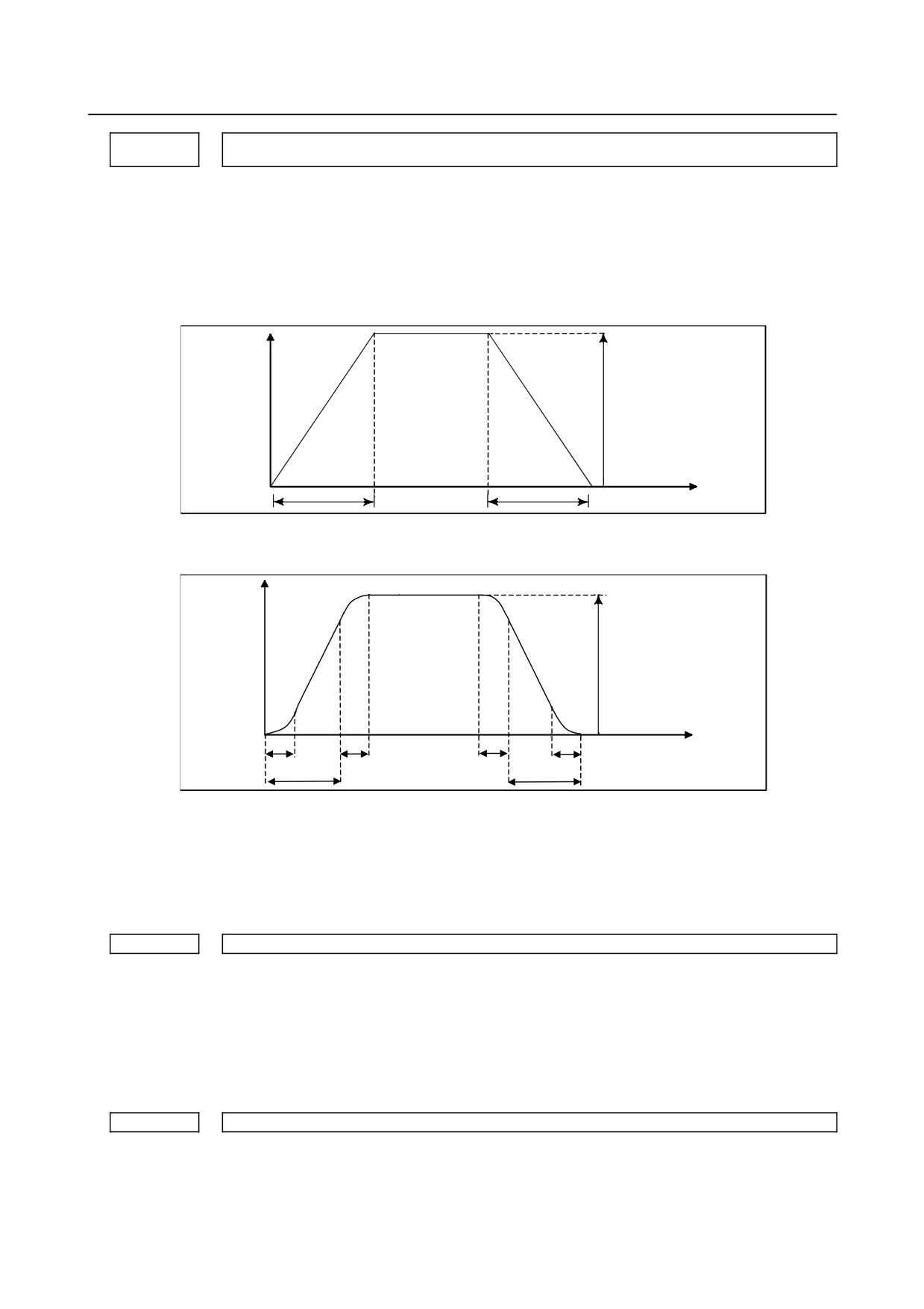
Specify a time constant used for acceleration/deceleration in rapid traverse.
[Example]
For linear acceleration/deceleration
Speed
Rapid traverse rate
(Parameter No. 1420)
T
T
Time
T : Setting of parameter No. 1620
For bell-shaped acceleration/deceleration
Speed
Rapid traverse rate
(Parameter No. 1420)
T2
T2
T2
T2
Time
T1
T1
T1
: Setting of parameter No. 1620
T2
: Setting of parameter No. 1621
(However, T1 ≥ T2 must be satisfied.)
Total acceleration (deceleration) time
: T1 + T2
Time for linear portion
: T1−T2
Time for curve portion
: T2 × 2
1621
Time constant T2 used for bell-shaped acceleration/deceleration in rapid traverse for each axis
[Input type] Parameter input
[Data type] Word axis
[Unit of data] msec
[Valid data range] 0 to 1000
Specify time constant T2 used for bell-shaped acceleration/ deceleration in rapid traverse
for each axis.
1622
Time constant of acceleration/deceleration in cutting feed for each axis
[Input type] Parameter input
[Data type] Word axis
[Unit of data] msec
- 73 -
4.DESCRIPTION OF PARAMETERS
B-64310EN/02
[Valid data range] 0 to 4000
Set the time constant used for exponential acceleration/deceleration in cutting feed,
bell-shaped
acceleration/deceleration
after
interpolation
or
linear
acceleration/deceleration after interpolation in cutting feed for each axis. Which type to
use is selected with bits 1(CTBx) and 0(CTLx) of parameter No.1610. Except for special
applications, the same time constant must be set for all axes in this parameter. If the time
constants set for the axes differ from each other, proper straight lines and arcs cannot be
obtained.
1623
FL rate of exponential acceleration/deceleration in cutting feed for each axis
[Input type] Parameter input
[Data type] Real axis
[Unit of data] mm/min, inch/min, degree/min (machine unit)
[Min. unit of data] Depend on the increment system of the applied axis
[Valid data range] Refer to the standard parameter setting table (C)
(When the increment system is IS-B, 0.0 to +999000.0)
Set the lower limit (FL rate) of exponential acceleration/deceleration in cutting feed for
each axis.
NOTE
Except for special applications, set 0 for all axes in this parameter.
Otherwise, the correct straight line or arc shape cannot be
obtained.
1624
Time constant of acceleration/deceleration in jog feed for each axis.
[Input type] Parameter input
[Data type] Word axis
[Unit of data] msec
[Valid data range] 0 to 4000
Set the time constant used for acceleration/deceleration in jog feed for each axis.
1625
FL rate of exponential acceleration/deceleration in jog feed for each axis
[Input type] Parameter input
[Data type] Real axis
[Unit of data] mm/min, inch/min, degree/min (machine unit)
[Min. unit of data] Depend on the increment system of the applied axis
[Valid data range] Refer to the standard parameter setting table (C)
(When the increment system is IS-B, 0.0 to +999000.0)
Set the FL rate of exponential acceleration/deceleration in cutting feed for each axis.
This parameter allows only the exponential type.
Acceleration/deceleration time constant in threading cycles for each axis
1626
[Input type] Parameter input
[Data type] Word axis
[Unit of data] msec
[Valid data range] 0 to 4000
Set a time constant for acceleration/deceleration after interpolation in the threading cycles
G92 and G76 for each axis.
- 74 -
B-64310EN/02
4.DESCRIPTION OF PARAMETERS
FL rate for acceleration/deceleration in threading cycles for each axis
1627
[Input type] Parameter input
[Data type] Real axis
[Unit of data] mm/min, inch/min, degree/min (machine unit)
[Min. unit of data] Depend on the increment system of the applied axis
[Valid data range] Refer to the standard parameter setting table (C)
(When the increment system is IS-B, 0.0 to +999000.0)
Set an FL feedrate for acceleration/deceleration after interpolation in the threading cycles
G92 and G76 for each axis. Set 0 at all times except in a special case.
1660
Maximum allowable acceleration rate in acceleration/deceleration before interpolation for each axis
[Input type] Parameter input
[Data type] Real axis
[Unit of data] mm/sec2, inch/sec2, degree/sec2 (machine unit)
[Min. unit of data] Depend on the increment system of the applied axis
[Valid data range] Refer to the standard parameter setting table (D)
(When the machine system is metric system, 0.0 to +100000.0. When the machine system
is inch system, machine, 0.0 to +10000.0.)
Set a maximum allowable acceleration rate in acceleration/ deceleration before
interpolation for each axis.
If a value greater than 100000.0 is set, the value is clamped to 100000.0.
If 0 is set, the specification of 100000.0 is assumed. If 0 is set for all axes, however,
acceleration/deceleration before interpolation is not performed.
If a maximum allowable acceleration rate set for one axis is greater than a maximum
allowable acceleration rate set for another axis by a factor or 2 or more, the feedrate at a
corner where the direction of travel abruptly changes can decrease temporarily.
Maximum allowable acceleration rate in acceleration/deceleration before interpolation for linear rapid
1671
traverse for each axis
[Input type] Parameter input
[Data type] Real axis
[Unit of data] mm/sec2, inch/sec2, degree/sec2 (machine unit)
[Min. unit of data] Depend on the increment system of the applied axis
[Valid data range] Refer to the standard parameter setting table (D)
(When the machine system is metric system, 0.0 to +100000.0. When the machine system
is inch system, machine, 0.0 to +10000.0.)
Set a maximum allowable acceleration rate in acceleration/ deceleration before
interpolation for linear rapid traverse.
If a value greater than 100000.0, the value is clamped to 100000.0.
If 0 is set, the specification of the following is assumed:
1000.0 mm/sec2
100.0 inch/sec2
100.0 degrees/sec2
If 0 is specified for all axes, however, acceleration/deceleration before interpolation is not
performed.
Acceleration change time of bell-shaped acceleration/deceleration before interpolation for linear rapid
1672
traverse
[Input type] Parameter input
- 75 -
4.DESCRIPTION OF PARAMETERS
B-64310EN/02
[Data type] 2-word path
[Unit of data] msec
[Valid data range] 0 to 200
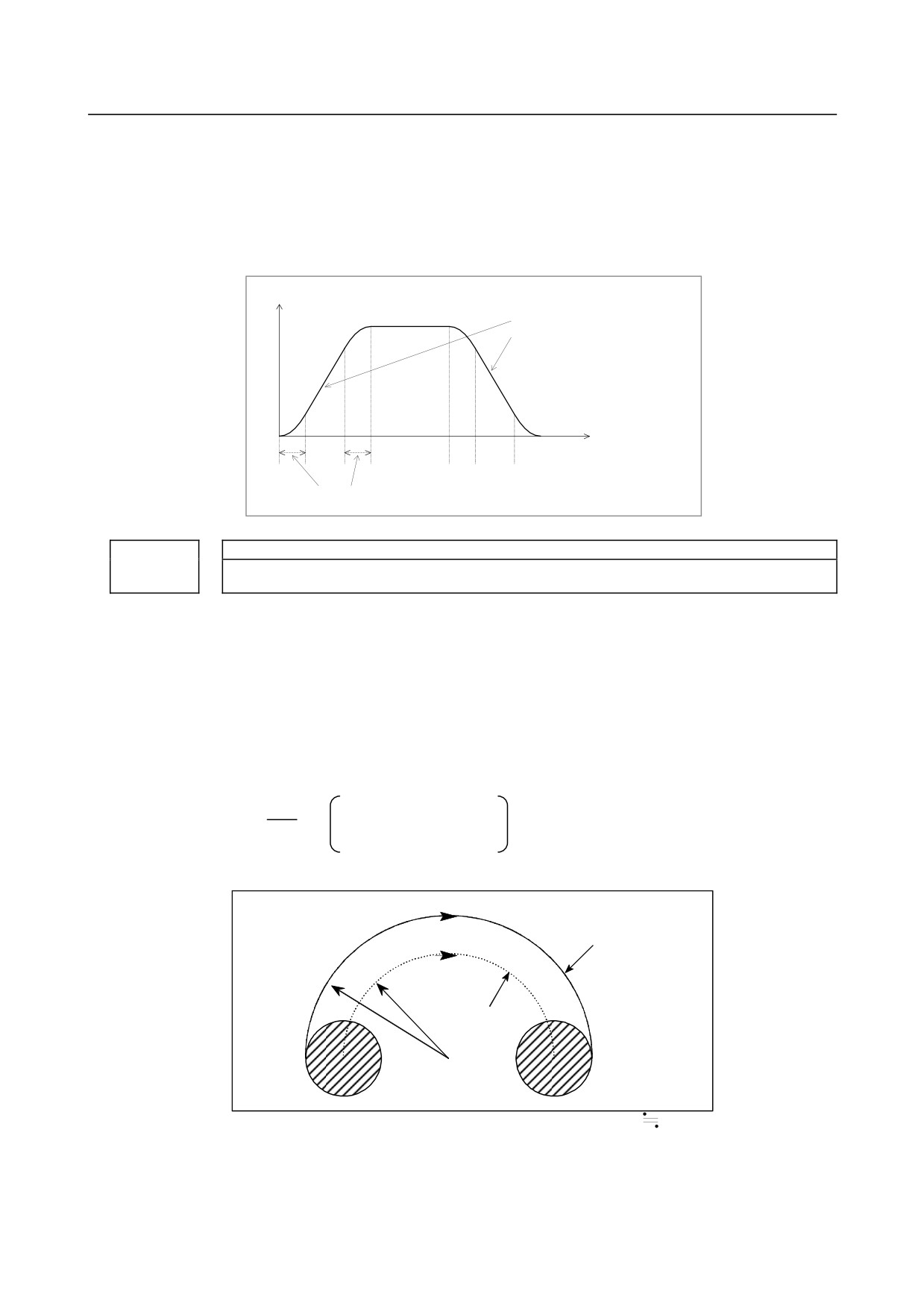
Set an acceleration change time of bell-shaped acceleration/ deceleration for linear rapid
traverse (time for changing from the state of constant feedrate (A) to the state of constant
acceleration/deceleration (C) at the acceleration rate calculated from the acceleration rate
set in parameter No. 1671: time of (B) in the figure below).
Feedrate in tangent direction
Maximum acceleration rate not exceeding
maximum allowable acceleration rate set by
parameter No.
1671 for each axis is
automatically calculated.
(A)
(B)
(C)
(B)
(A)
(B)
(C)
(B)
(A)
Tim e set by param eter No. 1672
1710
Minimum deceleration ratio (MDR) for inner circular cutting feedrate change by automatic corner
override
[Input type] Parameter input
[Data type] Byte path
[Unit of data] %
[Valid data range] 0 to 100
Set a minimum deceleration ratio (MDR) for an inner circular cutting feedrate change by
automatic corner override.
In the case of circular cutting offset inward, the actual feedrate is determined by a
specified feedrate (F) as follows:
Rc
Rc: Radius of tool center
F×
path
Rp
Rp: Programmed radius
Thus, the feedrate along the programmed path satisfies the specified value of F.
Programmed path
Rc
Tool center path
Rp
However, if Rc is too small when compared with Rp, Rc/Rp
0 results to stop the tool.
So, a minimum deceleration ratio (MDR) is set, and the feedrate of the tool is set to
F×(MDR) when Rc/Rp ≤ MDR.
- 76 -
B-64310EN/02
4.DESCRIPTION OF PARAMETERS
NOTE
When this parameter is set to 0, the minimum deceleration ratio
(MDR) is 100%.
1711
Inner determination angle (θp) for inner corner override
[Input type] Parameter input
[Data type] Real path
[Unit of data] deg
[Min. unit of data] Depend on the increment system of the reference axis
[Valid data range] 2 to 178
Set an inner determination angle for inner corner override in automatic corner overriding.
1712
Override value for inner corner override
[Input type] Parameter input
[Data type] Byte path
[Unit of data] %
[Valid data range] 1 to 100
Set an inner corner override value in automatic corner overriding.
1713
Start distance (Le) for inner corner override
[Input type] Setting input
[Data type] Real path
[Unit of data] mm, inch (input unit)
[Min. unit of data] Depend on the increment system of the reference axis
[Valid data range] 9 digit of minimum unit of data (refer to standard parameter setting table (A))
(When the increment system is IS-B, -999999.999 to +999999.999)
Set a start distance for inner corner override in automatic corner overriding.
1714
End distance (Ls) for inner corner override
[Input type] Setting input
[Data type] Real path
[Unit of data] mm, inch (input unit)
[Min. unit of data] Depend on the increment system of the reference axis
[Valid data range] 9 digit of minimum unit of data (refer to standard parameter setting table (A))
(When the increment system is IS-B, -999999.999 to +999999.999)
Set an end distance for inner corner override in automatic corner overriding.
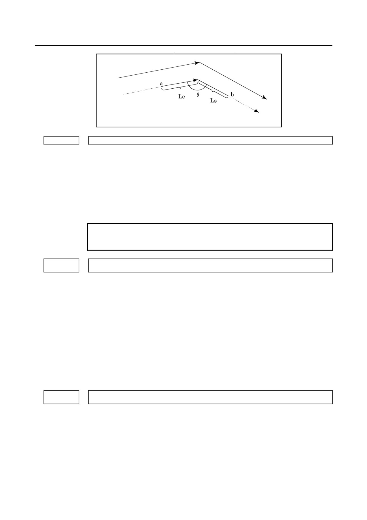
When θ ≤ θp, an inner corner is assumed. (Parameter No. 1711 is used to set θp.)
When a corner is determined to be an inner corner, an override is applied to the feedrate
in the range of Le in the previous block from the intersection of the corner and in the
range of Ls in the next block from the intersection of the corner.
Distances Le and Ls represent linear distances from the intersection of a corner to points
on the tool center path.
Le and Ls are set in parameter No. 1713 and No. 1714.
- 77 -
4.DESCRIPTION OF PARAMETERS
B-64310EN/02
Programmed path
Tool center path
An override is applied to the range from point a to point b.
1722
Rapid traverse feedrate reduction ratio for overlapping rapid traverse blocks
[Input type] Parameter input
[Data type] Byte axis
[Unit of data] %
[Valid data range] 0 to 100
This parameter is used when rapid traverse blocks are arranged successively, or when a
rapid traverse block is followed by a block that does not cause, movement. When the
feedrate for each axis of a block is reduced to the ratio set in this parameter, the execution
of the next block is started.
NOTE
The parameter No.1722 is effective when parameter No.1601 #4
(RTO) is set to 1.
Minimum allowable feedrate for the deceleration function based on acceleration in circular
1732
interpolation
[Input type] Parameter input
[Data type] Real path
[Unit of data] mm/min, inch/min, degree/min (machine unit)
[Min. unit of data] Depend on the increment system of the reference axis
[Valid data range] Refer to the standard parameter setting table (C)
(When the increment system is IS-B, 0.0 to +999000.0)
With the deceleration function based on acceleration in circular interpolation, an optimum
feedrate is automatically calculated so that acceleration produced by changing the move
direction in circular interpolation does not exceed the maximum allowable acceleration
rate specified in parameter No. 1735.
If the radius of an arc is very small, a calculated feedrate may become too low.
In such a case, the feedrate is prevented from decreasing below the value specified in this
parameter.
Maximum allowable acceleration rate for the deceleration function based on acceleration in circular
1735
interpolation for each axis
[Input type] Parameter input
[Data type] Real axis
[Unit of data] mm/sec2, inch/sec2, degree/sec2 (machine unit)
[Min. unit of data] Depend on the increment system of the applied axis
[Valid data range] Refer to the standard parameter setting table (D)
(When the machine system is metric system, 0.0 to +100000.0. When the machine system
is inch system, machine, 0.0 to +10000.0.)
Set a maximum allowable acceleration rate for the deceleration function based on
acceleration in circular interpolation.
- 78 -
B-64310EN/02
4.DESCRIPTION OF PARAMETERS
Feedrate is controlled so that acceleration produced by changing the move direction in
circular interpolation does not exceed the value specified in this parameter.
For an axis with 0 set in this parameter, the deceleration function based on acceleration is
disabled.
If a different value is set in this parameter for each axis, a feedrate is determined from the
smaller of the acceleration rates specified for the two circular axes.
1737
Maximum allowable acceleration rate for the deceleration function based on acceleration in AI contour
control for each axis
[Input type] Parameter input
[Data type] Real axis
[Unit of data] mm/sec2, inch/sec2, degree/sec2 (machine unit)
[Min. unit of data] Depend on the increment system of the applied axis
[Valid data range] Refer to the standard parameter setting table (D)
(When the machine system is metric system, 0.0 to +100000.0. When the machine system
is inch system, machine, 0.0 to +10000.0.)
Set a maximum allowable acceleration rate produced by changing the tool move
direction.
For an axis with 0 set in this parameter, the deceleration function based on acceleration is
disabled. If 0 is set for all axes, the deceleration function based on acceleration is not
performed.
In circular interpolation, however, the deceleration function based on feedrate control
using acceleration in circular interpolation (parameter No. 1735) is enabled.
1738
Minimum allowable feedrate for the deceleration function based on acceleration in AI contour control
[Input type] Parameter input
[Data type] Real path
[Unit of data] mm/min, inch/min, degree/min (machine unit)
[Min. unit of data] Depend on the increment system of the reference axis
[Valid data range] Refer to the standard parameter setting table (C)
(When the increment system is IS-B, 0.0 to +999000.0)
With the deceleration function based on acceleration in AI advanced preview control or
AI contour control, a feedrate most suitable for a desired figure is automatically
calculated.
Depending on the figure, however, the calculated feedrate may become too low.
In such a case, the feedrate is prevented from decreasing below the value specified in this
parameter.
FL rate for acceleration/deceleration after cutting feed interpolation for each axis in the
1763
acceleration/deceleration before interpolation mode
[Input type] Parameter input
[Data type] Real axis
[Unit of data] mm/min, inch/min, degree/min (machine unit)
[Min. unit of data] Depend on the increment system of the applied axis
[Valid data range] Refer to the standard parameter setting table (C)
(When the increment system is IS-B, 0.0 to +999000.0)
Set a minimum allowable feedrate (FL feedrate) for acceleration/ deceleration after
cutting feed interpolation in acceleration/ deceleration before interpolation as in advanced
preview control, AI advanced preview control, or AI contour control.
- 79 -
4.DESCRIPTION OF PARAMETERS
B-64310EN/02
Time constant for acceleration/deceleration after cutting feed interpolation in the
1769
acceleration/deceleration before interpolation mode
[Input type] Parameter input
[Data type] Word axis
[Unit of data] msec
[Valid data range] 0 to 4000
In the acceleration/deceleration before interpolation mode as in advanced preview control,
AI advanced preview control, or AI contour control, not the ordinary time constant
(parameter No. 1622) but the value of this parameter is used.
Be sure to specify the same time constant value for all axes except for a special
application. If different values are set, correct linear and circular figures cannot be
obtained.
1772
Acceleration change time of bell-shaped acceleration/deceleration before interpolation
[Input type] Parameter input
[Data type] 2-word path
[Unit of data] msec
[Valid data range] 0 to 200
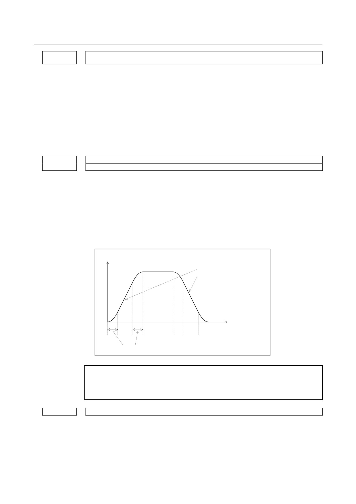
Set an acceleration change time of bell-shaped acceleration/ deceleration before
interpolation (time for changing from the state of constant feedrate (A) to the state of
constant acceleration/deceleration
(C) at the acceleration rate calculated from the
acceleration rate set in parameter No. 1660: time of (B) in the figure below).
Feedrate in tangent direction
Optimum inclination is automatically
calculated from the setting of parameter
No. 1660.
(A)
(B)
(C)
(B)
(A)
(B)
(C)
(B)
(A)
Time set by parameter No. 1772
NOTE
The option of bell-shaped acceleration/deceleration before
look-ahead interpolation is required. This parameter is valid only
in the AI contour control mode.
1783
Maximum allowable feedrate difference for feedrate determination based on corner feedrate difference
[Input type] Parameter input
[Data type] Real axis
[Unit of data] mm/min, inch/min, degree/min (machine unit)
[Min. unit of data] Depend on the increment system of the applied axis
[Valid data range] Refer to the standard parameter setting table (C)
(When the increment system is IS-B, 0.0 to +999000.0)
- 80 -
B-64310EN/02
4.DESCRIPTION OF PARAMETERS
If a feedrate component change for each axis exceeding the value set in this parameter
occurs at the joint of blocks, the feedrate determination function based on corner feedrate
difference finds a feedrate not exceeding the set value and performs deceleration by using
acceleration/deceleration before interpolation. Thus, a shock to the machine and
machining error at a corner can be reduced.
1788
Maximum allowable acceleration change rate in feedrate determination based on acceleration change
for each axis
[Input type] Parameter input
[Data type] Real axis
[Unit of data] mm/sec2, inch/sec2, degree/sec2 (machine unit)
[Min. unit of data] Depend on the increment system of the applied axis
[Valid data range] Refer to the standard parameter setting table (D)
(When the machine system is metric system, 0.0 to +100000.0. When the machine system
is inch system, machine, 0.0 to +10000.0.)
Set a maximum allowable acceleration change rate for each axis in feedrate control based
on acceleration change under control on the rate of change of acceleration.
For an axis with 0 set in this parameter, feedrate control based on acceleration change is
disabled.
If 0 is set for all axes, feedrate control based on acceleration change is not exercised.
1789
Maximum allowable acceleration change rate in feedrate determination based on acceleration change
for each axis (linear interpolation)
[Input type] Parameter input
[Data type] Real axis
[Unit of data] mm/sec2, inch/sec2, degree/sec2 (machine unit)
[Min. unit of data] Depend on the increment system of the applied axis
[Valid data range] Refer to the standard parameter setting table (D)
(When the machine system is metric system, 0.0 to +100000.0. When the machine system
is inch system, machine, 0.0 to +10000.0.)
Set a maximum allowable acceleration change rate for each axis in feedrate control based
on acceleration change under control on the rate of change of acceleration in successive
linear interpolation operations.
In feedrate control based on acceleration change at a corner between linear interpolation
operations, the maximum allowable acceleration change rate not set in parameter
No.1788 but set in this parameter is valid.
For an axis with 0 set in this parameter, the maximum allowable acceleration change rate
set in parameter No.1788 is valid.
Feedrate control based on acceleration change is disabled for an axis with 0 set in
parameter No.1788, so that the setting of this parameter for such an axis is ignored.
1790
Ratio of change time of the rate of change of acceleration in smooth bell-shaped
acceleration/deceleration before interpolation
[Input type] Parameter input
[Data type] Byte path
[Unit of data] %
[Valid data range] 0 to 50
Set the ratio of the change time of the rate of change of acceleration to the change time of
acceleration
(*1) by percentage
(%) in smooth bell-shaped acceleration/deceleration
before look-ahead interpolation.
- 81 -
4.DESCRIPTION OF PARAMETERS
B-64310EN/02
If 0 is set in this parameter or a value not within the valid data range is specified in this
parameter, smooth bell-shaped acceleration/ deceleration before look-ahead interpolation
is not performed.
(*1) Parameter No. 1772 for acceleration/deceleration before look-ahead interpolation
(cutting feed).
Parameter No. 1672 for acceleration/deceleration before interpolation in linear rapid
traverse.
4.16 PARAMETERS OF SERVO (1 OF 2)
#7
#6
#5
#4
#3
#2
#1
#0
1800
RBK
FFR
CVR
[Input type] Parameter input
[Data type] Bit path
#1 CVR When velocity control ready signal VRDY is set ON before position control ready signal
PRDY comes ON
0: A servo alarm is generated.
1: A servo alarm is not generated.
#3 FFR Feed-forward control in rapid traverse is:
0: Disabled
1: Enabled
Feed-forward is enabled only in normal cutting feed. When this parameter is set to 1,
feed-forward is enabled in rapid traverse as well. This capability reduces the servo
positional deviation, thus reducing the time required to enter the in-position width at the
time of positioning.
#4 RBK Backlash compensation applied separately for cutting feed and rapid traverse
0: Not performed
1: Performed
#7
#6
#5
#4
#3
#2
#1
#0
1801
CIN
CCI
[Input type] Parameter input
[Data type] Bit path
#4 CCI As the in-position width for cutting feed:
0: The parameter (No. 1826) applicable to rapid traverse as well is used.
1: The parameter (No. 1827) dedicated to cutting feed is used.
This parameter enables the in-position width for cutting feed (parameter No. 1827) to be
set instead of the in-position width for rapid traverse (parameter No. 1826).
By setting bit 4 (CCI) of parameter No. 1801, choose whether to use this function or the
conventional in-position check function.
This function, when specified, is enabled for all axes. So, for an axis that does not require
this function, set the same data in parameter No. 1826 and No. 1827.
#5 CIN When CCI is set to 1, the dedicated parameter for specifying an in-position width for
cutting feed is used:
0: Only when the next block specifies cutting feed.
1: Regardless of the next block.
- 82 -