FANUC Series 0i-MODEL D, Series 0i Mate-MODEL D. PARAMETER MANUAL - page 2
B-64310EN/02
4.DESCRIPTION OF PARAMETERS
NOTE
When this parameter is set, the power must be turned off before
operation is continued.
#0 IO4 Separate control of I/O channel numbers is:
0: Not performed.
1: Performed.
If the I/O channels are not separately controlled, set the input/output device in parameter
No. 0020.
If the I/O channels are separately controlled, set the input device and output device in the
foreground and the input device and output device in the background in parameters No.
0020 to No. 0023 respectively.
Separate control of I/O channels makes it possible to perform background editing,
program input/output, and the like during the DNC operation.
#7
#6
#5
#4
#3
#2
#1
#0
MNC
SCH
MDP
0138
MNC
SCH
[Input type] Parameter input
[Data type] Bit
#0 MDP To the extensions of input/output files, a path number is:
0: Not added.
1: Added.
NOTE
If a file name is specified by setting F, this parameter is ignored, and
a path number is not added to the extension.
#5 SCH The schedule operation function is:
0: Disabled.
1: Enabled.
#7 MNC DNC operation from the memory card and external device subprogram call from the
memory card are:
0: Not performed.
1: Performed.
#7
#6
#5
#4
#3
#2
#1
#0
0139
ISO
[Input type] Setting input
[Data type] Bit
#0 ISO When a memory card is selected as an I/O device, data input/output is performed using
0: ASCII codes
1: ISO codes
WARNING
1 Unless data is input using ASCII codes, set this parameter to 1 to
input or output data using ISO codes.
- 23 -
4.DESCRIPTION OF PARAMETERS
B-64310EN/02
WARNING
2 Data input/output with ASCII codes is dangerous because parity
information is not included and a data error during the data
input/output is not detected.
4.5.2
Parameters of Channel 1 (I/O CHANNEL=0)
#7
#6
#5
#4
#3
#2
#1
#0
0101
NFD
ASI
SB2
[Input type] Parameter input
[Data type] Bit
#0 SB2 The number of stop bits
0:
1
1:
2
#3 ASI The codes used during data input/output is:
0: EIA or ISO codes (input: automatic detection, output: setting of bit 1 (ISO) of
parameter No. 0000)
1: ASCII codes during input and output
NOTE
To use ASCII codes for data input/output (by setting ASI to 1), set
bit 1 (ISO) of parameter No. 0000 to 1.
#7 NFD Feed before and after the data at data output
0: Output
1: Not output
When input/output devices other than the FANUC PPR are used, set NFD to 1.
0102
Number specified for the input/output device (when the I/O CHANNEL is set to 0)
[Input type] Parameter input
[Data type] Byte
[Valid data range] 0 to 6
Set the specification number of the input/output device corresponding to I/O
CHANNEL=0.
The following table lists the specification numbers and corresponding input/output device
specifications.
Specification numbers and corresponding input/output device specifications
Specification number
Input/output device specification
0
RS-232-C (control codes DC1 to DC4 are used)
1
FANUC CASSETTE ADAPTOR 1(FANUC CASSETTE B1/B2)
2
FANUC CASSETTE ADAPTOR 3(FANUC CASSETTE F1)
3
FANUC PROGRAM FILE Mate、FANUC FA Card Adaptor,
FANUC FLOPPY CASSETTE ADAPTOR, FANUC Handy File
FANUC SYSTEM P-MODEL H
4
RS-232-C (control codes DC1 to DC4 are not used)
5
Portable tape reader
6
FANUC PPR
FANUC SYSTEM P-MODEL G, FANUC SYSTEM P-MODEL H
- 24 -
B-64310EN/02
4.DESCRIPTION OF PARAMETERS
0103
Baud rate (when I/O CHNNEL is set to 0)
[Input type] Parameter input
[Data type] Byte
[Valid data range] 1 to 12
Set the baud rate of the input/output device corresponding to I/O CHANNEL=0.
When setting this parameter, see the following table:
Baud rates and corresponding settings
Setting
Baud rate (bps)
Setting
Baud rate (bps)
1
50
8
1200
3
110
9
2400
4
150
10
4800
6
300
11
9600
7
600
12
19200
4.5.3
Parameters of Channel 1 (I/O CHANNEL=1)
#7
#6
#5
#4
#3
#2
#1
#0
0111
NFD
ASI
SB2
[Input type] Parameter input
[Data type] Bit
#0 SB2 The number of stop bits
0:
1
1:
2
#3 ASI The codes used during data input/output is:
0: EIA or ISO codes (input: automatic detection, output: setting of bit 1 (ISO) of
parameter No. 0000)
1: ASCII codes during input and output
NOTE
To use ASCII codes for data input/output (by setting ASI to 1), set
bit 1 (ISO) of parameter No. 0000 to 1.
#7 NFD Feed before and after the data at data output
0: Output
1: Not output
When input/output devices other than the FANUC PPR are used, set NFD to 1.
0112
Number specified for the input/output device (when the I/O CHANNEL is set to 1)
[Input type] Parameter input
[Data type] Byte
[Valid data range] 0 to 6
Set the specification number of the input/output device corresponding to I/O
CHANNEL=1.
0113
Baud rate (when I/O CHNNEL is set to 1)
[Input type] Parameter input
- 25 -
4.DESCRIPTION OF PARAMETERS
B-64310EN/02
[Data type] Byte
[Valid data range] 1 to 12
Set the baud rate of the input/output device corresponding to I/O CHANNEL=1.
4.5.4
Parameters of Channel 2 (I/O CHANNEL=2)
#7
#6
#5
#4
#3
#2
#1
#0
0121
NFD
ASI
SB2
[Input type] Parameter input
[Data type] Bit
#0 SB2 The number of stop bits
0:
1
1:
2
#3 ASI The codes used during data input/output is:
0: EIA or ISO codes (input: automatic detection, output: setting of bit 1 (ISO) of
parameter No. 0000)
1: ASCII codes during input and output
NOTE
To use ASCII codes for data input/output (by setting ASI to 1), set
bit 1 (ISO) of parameter No. 0000 to 1.
#7 NFD Feed before and after the data at data output
0: Output
1: Not output
0122
Number specified for the input/output device (when the I/O CHANNEL is set to 2)
[Input type] Parameter input
[Data type] Byte
[Valid data range] 0 to 6
Set the specification number of the input/output device corresponding to
I/O
CHANNEL=2.
0123
Baud rate (when I/O CHNNEL is set to 2)
[Input type] Parameter input
[Data type] Byte
[Valid data range] 1 to 12
Set the baud rate of the input/output device corresponding to I/O CHANNEL=2.
4.6
PARAMETERS OF CNC SCREEN DISPLAY FUNCTIONS
#7
#6
#5
#4
#3
#2
#1
#0
0300
PCM
[Input type] Setting input
[Data type] Bit
- 26 -
B-64310EN/02
4.DESCRIPTION OF PARAMETERS
#0 PCM If the CNC screen display function is enabled, when a memory card interface is provided
on the NC side,
0: The memory card interface on the NC side is used.
1: The memory card interface on the PC side is used.
4.7
PARAMETERS OF ETHERNET/DATA SERVER
FUNCTIONS
#7
#6
#5
#4
#3
#2
#1
#0
0901
EFT
[Input type] Parameter input
[Data type] Bit path
#1 EFT The FTP file transfer function by the Ethernet function is:
0: Not used.
1: Used.
NOTE
In a 2-path system, the setting of the parameter for path 1 is used
throughout the system.
#7
#6
#5
#4
#3
#2
#1
#0
0904
LCH
DHC
DNS
UNM
D1E
[Input type] Parameter input
[Data type] Bit
#3 D1E When the DHCP function is used:
0: Default parameters for the FOCAS2/Ethernet functions are set.
Port number (TCP)
8193
Port number (UDP)
0
Time interval
0
1: Default parameters for FANUC i CELL communication are set.
Port number (TCP)
8193
Port number (UDP)
8192
Time interval
50
#4 UNM The CNC Unsolicited Messaging function is:
0: Not used.
1: Used.
#5 DNS The DNS client function is:
0: Not used.
1: Used.
#6 DHC The DHCP client function is:
0: Not used.
1: Used.
- 27 -
4.DESCRIPTION OF PARAMETERS
B-64310EN/02
#7 LCH In the LIST-GET service of the Data Server function, when a list file specifies 1025 or
more files:
0: A check for duplicated file names is performed.
1: A check for duplicated file names is not performed.
#7
#6
#5
#4
#3
#2
#1
#0
0905
UNS
DSF
PCH
DNE
[Input type] Parameter input
[Data type] Bit
#0 DNE During DNC operation using the FOCAS2/Ethernet functions, the termination of DNC
operation is:
0: Waited.
1: Not waited.
#1 PCH At the start of communication of the Data Server function, FTP file transfer function, or
machine remote diagnosis function, checking for the presence of the server using PING
is:
0: Performed.
1: Not performed.
NOTE
Usually, set 0.
If 1 is set not to check the presence of the server by using PING, it
may take several tens of seconds to recognize an error when the
server is not present in the network.
For mainly security reasons, a personal computer may be set so
that it does not respond to the PING command. To communicate
with such a personal computer, set 1.
#3 DSF When an NC program is stored on the memory card of the Data Server:
0: The file name takes priority.
1: The program name in the NC program takes priority.
NOTE
Only when the file of the personal computer side is registered to
the memory card of the data server by operating the CNC side, this
parameter becomes effective.
#4 UNS In the CNC Unsolicited Messaging function, when the end of the function is requested by
other than the CNC Unsolicited Messaging server currently connected:
0: The request for the end of the function is rejected.
1: The request for the end of the function is accepted.
#7
#6
#5
#4
#3
#2
#1
#0
0908
ISO
[Input type] Setting input
[Data type] Bit
#0 ISO When the data server is selected as an I/O device, data is input or output using:
0: ASCII codes
1: ISO codes
- 28 -
B-64310EN/02
4.DESCRIPTION OF PARAMETERS
0921
Selects the host computer 1 OS.
0922
Selects the host computer 2 OS.
0923
Selects the host computer 3 OS.
[Input type] Parameter input
[Data type] Word
[Valid data range] 0 to 2
0: Windows95/98/Me/2000/XP/Vista/7.
1: UNIX, VMS.
2: Linux.
NOTE
Some FTP server software products do not depend on the OS. So,
even when the above parameters are set, it is sometimes
impossible to display a list of files properly.
0924
FOCAS2/Ethernet waiting time setting
[Input type] Parameter input
[Data type] Word
[Unit of data] millisecond
[Valid data range] 0 to 32767
When the FOCAS2/Ethernet and Data Server functions are used simultaneously, this
parameter sets the FOCAS2/Ethernet function waiting time in milliseconds.
When a value of 0 is set, the functions operate with assuming that 1 millisecond is
specified.
0929
File attribute specification during FTP server operation
[Input type] Parameter input
[Data type] Word
[Valid data range] 0 to 2
This parameter sets whether to give priority to the file attribute specified in a TYPE
command of FTP during operation as an FTP server.
0: Priority is given to the file attribute specified in a TYPE command from an FTP
client.
1: Text files are always assumed.
2: Binary files are always assumed.
Maximum number of files that can be registered to the memory card of the Data Server and maximum
0930
size per file that can be registered
[Input type] Parameter input
[Data type] Word
[Valid data range] 0, 10 to 15
No.930
Maximum number of files
Maximum size per file
0
2047
512MB
10
511
2048MB
11
1023
1024MB
12
2047
512MB
- 29 -
4.DESCRIPTION OF PARAMETERS
B-64310EN/02
No.930
Maximum number of files
Maximum size per file
13
4095
256MB
14
8191
128MB
15
16383
64MB
NOTE
1 When the memory card is formatted after this parameter is set, the
maximum number of files and maximum size per file are changed.
2 Each folder is counted as one file.
4.8
PARAMETERS OF POWER MATE CNC
#7
#6
#5
#4
#3
#2
#1
#0
0960
PPE
PMN
MD2
MD1
[Input type] Parameter input
[Data type] Bit path
# 1, 2 MD1,MD2 These parameters set a slave parameter input/output destination.
Parameter MD2
Parameter MD1
I/O destination
0
0
Program memory
0
1
Memory card
NOTE
The output destination depends on the setting for path 1.
#3 PMN The Power Mate CNC manager function is:
0: Enabled.
1: Disabled.
When priority is to be given to commands to slaves by a ladder (communication by the
Power Mate CNC manager function is to be stopped) after necessary data setting and
checking for each of the connected slaves are completed, set this bit to 1 for every path.
#4 PPE
0: The Power Mate CNC manager can set slave parameters at all times.
1: Slave parameter setting by the Power Mate CNC manager follows the setting of
PWE for the host CNC. When PWE = 0, the setting of the I/O LINK β parameter is
prohibited.
#7
#6
#5
#4
#3
#2
#1
#0
0961
PMO
[Input type] Parameter input
[Data type] Bit
#3 PMO The O number of a program for saving and restoring the I/O LINK β parameter is set
based on:
0: Group number and channel number
1: Group number only
- 30 -
B-64310EN/02
4.DESCRIPTION OF PARAMETERS
4.9
PARAMETERS OF SYSTEM CONFIGURATION
0980
Machine group number to which each path belongs
NOTE
When this parameter is set, the power must be turned off before
operation is continued.
[Input type] Parameter input
[Data type] Byte path
[Valid data range] 1
Set the machine group number to which each path belongs.
For the 0i-D/0i Mate-D, be sure to set this parameter to 1.
NOTE
If this parameter is set to 0, a setting of 1 is assumed.
0981
Absolute path number to which each axis belongs
NOTE
When this parameter is set, the power must be turned off before
operation is continued.
[Input type] Parameter input
[Data type] Byte axis
[Valid data range] 1, 2
Set the path to which each axis belongs.
NOTE
1 When 0 is set for all axes, the parameter is automatically set
according to the number of controlled axes of each path.
2 When the setting falls outside the range, the axis is assumed to
belong to the first path.
0982
Absolute path number to which each spindle belongs
NOTE
When this parameter is set, the power must be turned off before
operation is continued.
[Input type] Parameter input
[Data type] Byte spindle
[Valid data range] 1, 2
Set the path to which each spindle belongs.
NOTE
1 When 0 is set for all axes, the parameter is automatically set
according to the number of controlled axes of each path.
- 31 -
4.DESCRIPTION OF PARAMETERS
B-64310EN/02
NOTE
2 When the setting falls outside the range, the axis is assumed to
belong to the first path.
3 When spindle control with servo motor is enabled, the servo motor
used as the spindle controlled axis is treated as a spindle.
Therefore, it is necessary to set the path to which the axis subject
to spindle control with servo motor.
0983
Path control type of each path
NOTE
1 When this parameter is set, the power must be turned off before
operation is continued.
2 For the 0i -D/0i Mate-D, this parameter does not need to be set
because it is set automatically.
[Input type] Parameter input
[Data type] Byte path
[Valid data range] 0 to 1
Set the path control type of each path.
The following two path control types are available:
T series (lathe system)
:
0
M series (machining system):
1
4.10 PARAMETERS OF AXIS CONTROL/INCREMENT SYSTEM
#7
#6
#5
#4
#3
#2
#1
#0
1001
INM
[Input type] Parameter input
[Data type] Bit path
NOTE
When this parameter is set, the power must be turned off before
operation is continued.
#0 INM Least command increment on the linear axis
0: In mm (metric system machine)
1: In inches (inch system machine)
#7
#6
#5
#4
#3
#2
#1
#0
1002
IDG
XIK
AZR
JAX
[Input type] Parameter input
[Data type] Bit path
#0 JAX Number of axes controlled simultaneously in jog feed, manual rapid traverse and manual
reference position return
0:
1 axis
1:
3 axes
- 32 -
B-64310EN/02
4.DESCRIPTION OF PARAMETERS
#3 AZR When no reference position is set, the G28 command causes:
0: Reference position return using deceleration dogs
(as during manual reference
position return) to be executed.
1: Alarm (PS0304) "G28 was specified when no reference position is set" to be
displayed.
NOTE
When reference position return without dogs is specified, (when bit 1
(DLZ) of parameter No.1005 is set to 1) the G28 command specified
before a reference position is set causes an alarm PS0304 to be
issued, regardless of the setting of AZR.
#4
XIK When bit 1 (LRP) of parameter No.1401, is set to 0, namely, when positioning is
performed using non-linear type positioning, if an interlock is applied to the machine
along one of axes in positioning,
0: The machine stops moving along the axis for which the interlock is applied and
continues to move along the other axes.
1: The machine stops moving along all the axes.
#7
IDG When the reference position is set without dogs, automatic setting of bit 0 (IDGx) of
parameter No.1012 to prevent the reference position from being set again is:
0: Not performed.
1: Performed.
NOTE
When this parameter is set to 0, bit 0 (IDGx) of parameter No. 1012
is invalid.
#7
#6
#5
#4
#3
#2
#1
#0
IPR
1004
IPR
IPI
[Input type] Parameter input
[Data type] Bit path
#6 IPI Bit 7 (IPR) of parameter No. 1004 is:
0: A parameter that requires a power-off operation to make the setting valid, and that
becomes invalid for inch input.
1: A parameter that does not require a power-off operation, and that is also valid for
inch input.
#7 IPR Whether the least input increment for each axis is set to a value 10 times as large as the
least command increment is specified, in increment systems of IS-B or IS-C at setting
mm.
0: The least input increment is not set to a value 10 times as large as the least command
increment.
1: The least input increment is set to a value 10 times as large as the least command
increment.
If IPR is set to 1, the least input increment is set as follows:
Input increment
Least input increment
IS-B
0.01 mm, 0.01 deg, or 0.0001 inch
IS-C
0.001 mm, 0.001 deg, or 0.00001 inch
- 33 -
4.DESCRIPTION OF PARAMETERS
B-64310EN/02
NOTE
For IS-A, the least input increment cannot be set to a value 10
times as large as the least command increment.
The least input increment is not multiplied by 10 also when the
calculator-type decimal point input (bit 0 (DPI) of parameter No.
3401) is used.
#7
#6
#5
#4
#3
#2
#1
#0
1005
RMBx
MCCx
EDMx
EDPx
HJZx
DLZx
ZRNx
[Input type] Parameter input
[Data type] Bit axis
#0 ZRNx If a move command other than G28 is specified by automatic operation when no
reference position return is performed yet after the power is turned on:
0: The alarm (PS0224) "PERFORM REFERENCE POSITION RETURN." is issued.
1: Operation is performed without issuing an alarm.
NOTE
1 The state in which a reference position has not been established
refers to the following state:
- When an absolute position detector is not used and reference
position return has not been performed even once after power-up
- When an absolute position detector is used and the association of
the machine position with the position detected with the absolute
position detector has not been completed (See the description of
bit 4 (APZx) of parameter No. 1815.)
2 When the Cs axis coordinates are to be set up, set ZRN to 0.
#1 DLZx Function for setting the reference position without dogs
0: Disabled
1: Enabled
#3 HJZx When a reference position is already set:
0: Manual reference position return is performed with deceleration dogs.
1: Manual reference position return is performed using rapid traverse without
deceleration dogs, or manual reference position return is performed with
deceleration dogs, depending on the setting of bit 7 (SJZ) of parameter No.0002.
When the function for setting the reference position without dogs (see the description of
bit 1 (DLZx) of parameter No. 1005) is used, manual reference position return after a
reference position is set is always performed at a parameter-set feedrate, regardless of the
setting of HJZx.
#4 EDPx In cutting feed, an external deceleration signal in the + direction for each axis is:
0: Invalid
1: Valid
- 34 -

B-64310EN/02
4.DESCRIPTION OF PARAMETERS
NOTE
Be sure to set "1" to this parameter if bit 5 (EDR) of parameter
No.1405 is set to 0 when positioning of linear interpolation type is
used.
#5 EDMx In cutting feed, an external deceleration signal in the - direction for each axis is:
0: Invalid
1: Valid
NOTE
Be sure to set "1" to this parameter if bit 5 (EDR) of parameter
No.1405 is set to 0 when positioning of linear interpolation type is
used.
#6
MCCx If a multi-axis amplifier is used, and another axis of the same amplifier is placed in the
control axis detach state, the MCC signal of the servo amplifier is:
0: Turned off.
1: Not turned off.
NOTE
This parameter can be set for a control axis.
WARNING
1
When this parameter is set to 1, the dynamic brake does not
operate during removal of an axis. Therefore, if a failure occurs in
the mechanical brake, driving circuit, or sequence, a vertical axis
may fall freely in a significant manner. Since an excess error
check cannot also be performed during removal of an axis, set this
parameter to 0 for a vertical axis.
2
When the servo motor of a controlled axis to be detached is
connected to a multi-axis amplifier such as a two-axis amplifier,
placing the axis in the control axis detach state causes the
activating current in the amplifier to drop. As a result, alarm
(SV0401) "V READY OFF" is issued in the other axes. This alarm
can be suppressed by setting this parameter bit.
With this method, however, the target axis for the control axis
detach operation is placed in the servo off state (the amplifier
remains on, but no current flows through the motor). The torque of
the target axis becomes 0, so care should be taken. Even when a
controlled axis has been detached, detaching a cable (a command
cable or feedback cable) of the axis causes an alarm.
In such applications, it is impossible to perform a control axis
detach operation with a multi-axis amplifier by setting this
parameter bit. (Prepare a single-axis amplifier.)
#7
RMBx The control axis detachment signal for each axis and the setting input RMV (bit 7 of
parameter No. 0012) are:
0: Invalid
1: Valid
- 35 -

4.DESCRIPTION OF PARAMETERS
B-64310EN/02
#7
#6
#5
#4
#3
#2
#1
#0
1006
ZMIx
DIAx
ROSx
ROTx
[Input type] Parameter input
[Data type] Bit axis
NOTE
When at least one of these parameters is set, the power must be
turned off before operation is continued.
#0 ROTx
Setting linear or rotation axis.
#1
ROSx
Setting linear or rotation axis.
ROSx
ROTx
Meaning
0
0
Linear axis
(1) Inch/metric conversion is done.
(2) All coordinate values are linear axis type. (Is not rounded in 0 to 360°)
(3) Stored pitch error compensation is linear axis type (Refer to parameter
No.3624)
0
1
Rotation axis (A type)
(1) Inch/metric conversion is not done.
Machine coordinate values are rounded in 0 to 360°. Absolute coordinate
values are rounded or not rounded by parameter No.1008#0(ROAx) and
#2(RRLx).
(2) Stored pitch error compensation is the rotation type. (Refer to parameter
No.3624)
(3) Automatic reference position return (G28, G30) is done in the reference
position return direction and the move amount does not exceed one
rotation.
1
1
Rotation axis (B type)
(1) Inch/metric conversion, absolute coordinate values and relative
coordinate values are not done.
(2) Machine coordinate values, absolute coordinate values and relative
coordinate values are linear axis type. (Is not rounded in 0 to 360°).
(3) Stored pitch error compensation is linear axis type (Refer to parameter
No.3624)
(4) Cannot be used with the rotation axis roll over function and the index
table indexing function (M series)
Except for the above.
Setting is invalid (unused)
#3
DIAx The move command for each axis is based on:
0: Radius specification
1: Diameter specification
- 36 -
B-64310EN/02
4.DESCRIPTION OF PARAMETERS
NOTE
For the FS0i-C, one of the following changes is required besides
setting bit 3 (DIAx) of parameter No. 1006 so that the axis based
on diameter specification achieves the specified amount of
movement.
• Halve the command multiplication (the detection unit is not
changed).
• Halve the detection unit and double the flexible feed gear
(DMR).
For the FS0i-D, only if bit 3 (DIAx) of parameter No. 1006 is set,
the CNC halves the specified pulse. Accordingly, the above
changes are not required (when the detection unit is not changed).
To halve the detection unit, double both CMR and DMR.
#5 ZMIx The direction of manual reference position return is:
0:
+ direction
1:
- direction
#7
#6
#5
#4
#3
#2
#1
#0
1007
GRDx
ALZx
RTLx
[Input type] Parameter input
[Data type] Bit axis
#0 RTLx When manual reference position return is performed on a rotation axis (A type) with the
deceleration dog pressed before a reference position is established:
0: A movement is made at the reference position return feedrate FL.
1: Until a servo motor grid is established, a movement is not made at the reference
position return feedrate FL even if the deceleration dog is pressed, but a movement
is made at the rapid traverse rate.
If the deceleration dog is released after a movement at the rapid traverse rate and the
deceleration dog is then pressed again and released after the rotation axis makes one
revolution, reference position return operation is completed.
When this parameter is set to 0, the alarm (PS0090) "REFERENCE POSITION RETURN
FAILURE" is issued if the deceleration dog is released before a servo motor grid is
established.
If this alarm is issued, start manual reference position return at a position sufficiently far
away from the reference position.
#1
ALZx In automatic reference position return (G28):
0: Reference position return is performed by positioning (rapid traverse).
If no reference position return is performed after the power is turned on, however,
reference position return is performed using the same sequence as for manual
reference position return.
1: Reference position return is performed using the same sequence as for manual
reference position return.
NOTE
1 There is no effect on the axis for reference position return without
dogs.
- 37 -

4.DESCRIPTION OF PARAMETERS
B-64310EN/02
NOTE
2 When this parameter is 1, the settings of bit 3 (HJZx) of parameter
No. 1005 and bit 7 (SJZ) of parameter No. 0002 determine which
reference position return without deceleration dogs using rapid
traverse or reference position return with deceleration dogs is used.
#4 GRDx When absolute position detection is performed for an axis and the correspondence
between the machine position and the position on the absolute-position detector has not
yet been established for the axis, reference position setting without digs is:
0: Not performed more than once.
1: Performed more than once.
#7
#6
#5
#4
#3
#2
#1
#0
1008
RMCx
SFDx
RRLx
RABx
ROAx
[Input type] Parameter input
[Data type] Bit axis
NOTE
When at least one of these parameters is set, the power must be
turned off before operation is continued.
#0 ROAx The roll-over function of a rotation axis is
0: Invalid
1: Valid
NOTE
ROAx specifies the function only for a rotation axis (for which bit 0
(ROTx) of parameter No.1006, is set to 1)
#1 RABx In the absolute commands, the axis rotates in the direction
0: In which the distance to the target is shorter.
1: Specified by the sign of command value.
NOTE
RABx is valid only when ROAx is 1.
#2 RRLx Relative coordinates are
0: Not rounded by the amount of the shift per one rotation
1: Rounded by the amount of the shift per one rotation
NOTE
1 RRLx is valid only when ROAx is 1.
2 Assign the amount of the shift per one rotation in parameter No.1260.
#4 SFDx In reference position return based on the grid method, the reference position shift function
is:
0: Disabled
1: Enabled
- 38 -

B-64310EN/02
4.DESCRIPTION OF PARAMETERS
#5 RMCx When machine coordinate system selection (G53) is specified, bit 1 (RABx) of parameter
No. 1008 for determining the rotation direction of an absolute command for the roll-over
function of a rotation axis is:
0: Invalid
1: Valid
#7
#6
#5
#4
#3
#2
#1
#0
1012
IDGx
[Input type] Parameter input
[Data type] Bit axis
#0
IDGx The function for setting the reference position again, without dogs, is:
0: Not inhibited.
1: Inhibited.
(The alarm (PS0301) is issued.)
NOTE
IDGx is enabled when the IDG parameter (bit 7 of parameter
No.1002) is 1.
If the function for setting the reference position without dogs is
used, and the reference position is lost in absolute position
detection for a cause, the alarm (DS0300) is issued when the
power is turned on again.
If the operator performs reference position return, as a result of
mistakenly identifying the alarm as that requesting the operator to
perform a normal reference position return, an invalid reference
position may be set. To prevent such an operator error, the IDGx
parameter is provided to prevent the reference position from being
set again without dogs.
(1) If the IDG parameter (bit 7 of parameter No.1002) is set to 1,
the IDGx parameter (bit 0 of parameter No.1012) is
automatically set to 1 when the reference position is set using
the function for setting the reference position without dogs.
This prevents the reference position from being set again
without dogs.
(2) Once the reference position is prevented from being set for an
axis again, without dogs, any attempt to set the reference
position for the axis without dogs results in the output of an
alarm (PS0301).
(3) When the reference position must be set again without dogs,
set IDGx (bit 0 of parameter No.1012) to 0 before setting the
reference position.
#7
#6
#5
#4
#3
#2
#1
#0
1013
IESPx
ISCx
ISAx
[Input type] Parameter input
[Data type] Bit axis
- 39 -
4.DESCRIPTION OF PARAMETERS
B-64310EN/02
NOTE
When at least one of these parameters is set, the power must be
turned off before operation is continued.
#0 ISAx
#1 ISCx Increment system of each axis
Increment system
#1 ISCx
#0 ISAx
IS-A
0
1
IS-B
0
0
IS-C
1
0
#7 IESPx When the least input increment is C (IS-C), the function to allow to set the larger value to
the parameter of the speed and the acceleration:
0: Not used.
1: Used.
As for the axis which set this parameter when the least input increment is C (IS-C), the
larger value can be set to the parameter of the speed and the acceleration.
The valid data ranges of these parameters are indicated in the table of velocity and
angular velocity parameters in (C) of the standard parameter setting tables and the table
of acceleration and angular acceleration parameters in (D).
When this function is made effective, the digit number below the decimal point of the
parameter on input screen is changed. The digit number below the decimal point
decreases by one digit in case of the least input increment C (IS-C).
#7
#6
#5
#4
#3
#2
#1
#0
1014
CDMx
[Input type] Parameter input
[Data type] Bit axis
NOTE
When this parameter is set, the power must be turned off before
operation is continued.
#7 CDMx The Cs contour control axis is:
0: Not a virtual Cs axis
1: Virtual Cs axis
#7
#6
#5
#4
#3
#2
#1
#0
1015
DWT
WIC
ZRL
[Input type] Parameter input
[Data type] Bit path
#4 ZRL When a reference position is established, the tool path from the middle point to the
reference position and machine coordinate positioning (G53) in automatic reference
position return (G28) are based on:
0: Positioning of nonlinear interpolation type
1: Positioning of linear interpolation type
- 40 -
B-64310EN/02
4.DESCRIPTION OF PARAMETERS
NOTE
This parameter is valid when bit 1 (LRP) of parameter No. 1401 is
set to 1.
#6 WIC Workpiece origin offset measurement value direct input is:
0:
(M series)Performed without considering the external workpiece origin offset value.
(T series) Valid only in the currently selected workpiece coordinate system.
1:
(M series)Performed considering the external workpiece origin offset value.
(T series) Valid in all coordinate systems.
NOTE
In the T series, if this parameter bit is set to 0, workpiece origin
offset measurement value direct input is enabled only in the
currently selected workpiece coordinate system or an external
workpiece coordinate system. If an attempt is made to perform
workpiece origin offset measurement value direct input in a
workpiece coordinate system other than these workpiece
coordinate systems, warning "WRITE PROTECTED" is displayed.
#7 DWT When time for dwell per second is specified by P, the increment system:
0: Depends on the increment system
1: Does not depend on the increment system (1 ms)
1020
Program axis name for each axis
[Input type] Parameter input
[Data type] Byte axis
[Valid data range] 65 to 67,85 to 90
An axis name (parameter No. 1020) can be arbitrarily selected from 'A', 'B', 'C', 'U', 'V',
'W', 'X', 'Y', and 'Z'. (When G code system A is used with the T series, however, 'U', 'V',
and 'W' are not selectable.)
(Tip) ASCII code
Axis name
X
Y
Z
A
B
C
U
V
W
Setting
88
89
90
65
66
67
85
86
87
For the axes with axis names of 'X', 'Y', 'Z', and 'C' in G code system A of the T series, the
'U', 'V', 'W', and 'H' commands are the incremental commands of these axes.
NOTE
1 When G code system A is used in the T series, U, V, or W cannot
be used as an axis name.
2 The same axis name cannot be set for multiple axes.
3 When the second auxiliary function is provided (when bit 2 (BCD)
of parameter No. 8132 is 1), if the address (parameter No. 3460)
that specifies the second auxiliary function is used as an axis
name, the second auxiliary function is disabled.
4 When address C or A is used during chamfering/corner rounding or
direct drawing dimension programming (when bit 4 (CCR) of
parameter No. 3405 is 1) in the T series, address C or A cannot be
used as an axis name.
- 41 -
4.DESCRIPTION OF PARAMETERS
B-64310EN/02
NOTE
5 When the multiple repetitive turning canned cycle (T series) is
used, only 'X', 'Y', and 'Z' can be used for the address of the target
axis.
1022
Setting of each axis in the basic coordinate system
[Input type] Parameter input
[Data type] Byte axis
[Valid data range] 0 to 7
To determine a plane for circular interpolation, tool radius/tool nose radius compensation,
and so forth (G17: Xp-Yp plane, G18: Zp-Xp plane, G19: Yp-Zp plane), specify which of
the basic three axes (X, Y, and Z) is used for each control axis, or a parallel axis of which
basic axis is used for each control axis.
A basic axis (X, Y, or Z) can be specified only for one control axis.
Two or more control axes can be set as parallel axes for the same basic axis.
Setting
Meaning
0
Rotation axis (Neither the basic three axes nor a parallel axis)
1
X axis of the basic three axes
2
Y axis of the basic three axes
3
Z axis of the basic three axes
5
Axis parallel to the X axis
6
Axis parallel to the Y axis
7
Axis parallel to the Z axis
In general, the increment system and diameter/radius specification of an axis set as a
parallel axis are to be set in the same way as for the basic three axes.
1023
Number of the servo axis for each axis
NOTE
When this parameter is set, the power must be turned off before
operation is continued.
[Input type] Parameter input
[Data type] Byte axis
[Valid data range] 0 to Number of controlled axes
Set the servo axis for each control axis.
Usually set to same number as the control axis number.
The control axis number is the order number that is used for setting the axis-type
parameters or axis-type machine signals
• With an axis for which Cs contour control/spindle positioning is to be performed, set
-(spindle number) as the servo axis number.
Example)
When exercising Cs contour control on the fourth controlled axis by using the first
spindle, set -1.
- 42 -
B-64310EN/02
4.DESCRIPTION OF PARAMETERS
• For tandem controlled axes or electronic gear box (EGB) controlled axes, two axes
need to be specified as one pair. So, make a setting as described below.
Tandem axis:
For a master axis, set an odd (1, 3, 5, 7, ...) servo axis number. For a slave axis to be
paired, set a value obtained by adding 1 to the value set for the master axis.
EGB axis:
For a slave axis, set an odd (1, 3, 5, 7, ...) servo axis number. For a dummy axis to
be paired, set a value obtained by adding 1 to the value set for the slave axis.
1031
Reference axis
[Input type] Parameter input
[Data type] Byte path
[Valid data range] 1 to Number of controlled axes
The unit of some parameters common to all axes such as those for dry run feedrate and
one-digit F code feed may vary according to the increment system. An increment system
can be selected by a parameter on an axis-by-axis basis. So, the unit of those parameters
is to match the increment system of a reference axis. Set which axis to use as a reference
axis.
Among the basic three axes, the axis with the finest increment system is generally
selected as a reference axis.
4.11 PARAMETERS OF COORDINATES
#7
#6
#5
#4
#3
#2
#1
#0
WZR
NWS
ZCL
ZPR
1201
WZR
ZCL
ZPR
[Input type] Parameter input
[Data type] Bit path
#0 ZPR Automatic setting of a coordinate system when the manual reference position return is
performed
0: Not set automatically
1: Set automatically
NOTE
ZPR is valid when the workpiece coordinate system is not used
(when bit 0 (NWZ) of parameter No. 8136 is 1). When the
workpiece coordinate system is used, the workpiece coordinate
system is established based on the workpiece origin offset
(parameters No. 1220 to 1226) during a manual reference position
return, regardless of the setting of this parameter.
#2 ZCL Local coordinate system when the manual reference position return is performed
0: The local coordinate system is not canceled.
1: The local coordinate system is canceled.
- 43 -
4.DESCRIPTION OF PARAMETERS
B-64310EN/02
NOTE
ZCL is valid when the workpiece coordinate system is used (when
bit 0 (NWZ) of parameter No. 8136 is 0). To use the local
coordinate system (G52), set bit 0 (NWZ) of parameter No. 8136 to
0.
#6 NWS The workpiece coordinate system shift amount setting screen is:
0: Displayed
1: Not displayed
NOTE
When the workpiece coordinate shift amount setting screen is not
displayed, a workpiece coordinate system shift amount modification
using G10P0 cannot be made.
#7 WZR If the CNC is reset by the reset key on the MDI panel, external reset signal, reset and
rewind signal, or emergency stop signal when bit 6 (CLR) of parameter No. 3402 is set to
0, the G code of group number 14 (workpiece coordinate system) is:
0: Placed in the reset state (G code is not returned to G54)
1: Placed in the clear state (G code is returned to G54)
NOTE
When bit 6 (CLR) of parameter No. 3402 is set to 1, whether the G
code of group number 14 (workpiece coordinate system) is placed
in the clear state or reset state depends on the setting of bit 6
(C14) of parameter No. 3407.
#7
#6
#5
#4
#3
#2
#1
#0
RLC
G92
EWS
EWD
1202
RLC
G92
EWD
[Input type] Parameter input
[Data type] Bit path
#0 EWD The shift direction of the workpiece coordinate system is:
0: The direction specified by the external workpiece zero point offset value
1: In the opposite direction to that specified by the external workpiece zero point offset
value
#1 EWS The external workpiece zero point offset is made:
0: Valid
1: Invalid
- 44 -
B-64310EN/02
4.DESCRIPTION OF PARAMETERS
NOTE
When the external workpiece zero point offset is made invalid, the
following operation results:
1 As the external workpiece zero point offset on the workpiece
zero point offset setting screen, a workpiece coordinate system
shift amount is displayed.
2 Data keyed through the MDI panel for the workpiece coordinate
system shift amount and external workpiece zero point offset is
loaded into the memory for the workpiece coordinate system
shift amount.
3 A write to or read from the workpiece coordinate system shift
amount and external workpiece zero point offset with a macro
variable is performed using the respective memory.
4 A write to or read from the workpiece coordinate system shift
amount and external workpiece zero point offset with the window
function is performed using the respective memory.
#2 G92 When the workpiece coordinate system is used (when bit 0 (NWZ) of parameter No. 8136
is
0), if the G code (M series: G92, T series: G50) for coordinate system setting is
specified:
0: G command is executed and no alarm is issued.
1: G command is not executed and an alarm (PS0010) is issued.
#3 RLC Local coordinate system is
0: Not cancelled by reset
1: Cancelled by reset
NOTE
1 When bit 6 (CLR) of parameter No. 3402 is set to 0, and bit 7
(WZR) of parameter No. 1201 is set to 1, the local coordinate
system is cancelled, regardless of the setting of this parameter.
2 When bit 6 (CLR) of parameter No. 3402 is set to 1, and bit 6 (C14)
of parameter No. 3407 is set to 0, the local coordinate system is
cancelled, regardless of the setting of this parameter.
#7
#6
#5
#4
#3
#2
#1
#0
1203
EMS
[Input type] Parameter input
[Data type] Bit path
#0 EMS The extended external machine zero point shift function is:
0: Disabled.
1: Enabled.
NOTE
When the extended external machine zero point shift function is
enabled, the conventional external machine zero point shift function
is disabled.
- 45 -
4.DESCRIPTION OF PARAMETERS
B-64310EN/02
#7
#6
#5
#4
#3
#2
#1
#0
1205
WTC
[Input type] Parameter input
[Data type] Bit path
#7
WTC When workpiece coordinate system preset is done, actual tool length offset is:
0: Not considered.
1: Considered..
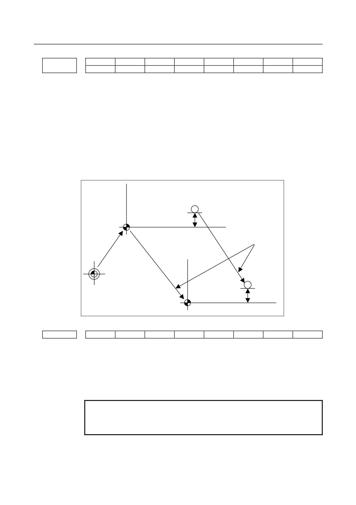
When this parameter is set “1”, it is possible to preset the workpiece coordinate system by
G-code, MDI operation or the workpiece coordinate system preset signal without
canceling the tool length compensation modes.
The compensation vector is kept as the below figure when the workpiece coordinate
system preset is done to the coordinate shifted by amount of movement during manual
intervention.
G54 workpiece coordinate
System before manual
Po
intervention
WZo
Tool length offset value
Amount of movement
during manual intervention
G54 workpiece coordinate
system after manual
intervention
Machine zero point
Pn
WZn
Tool length offset value
#7
#6
#5
#4
#3
#2
#1
#0
1206
HZP
[Input type] Parameter input
[Data type] Bit path
#1 HZP When a high-speed reference position return is performed, the coordinate system is:
0: Preset.
1: Not preset (FS0i-C-compatible specification).
NOTE
This parameter is valid when the workpiece coordinate system is
not used (when bit 0 (NWZ) of parameter No. 8136 is 1) and bit 0
(ZPR) of parameter No. 1201 is 0.
- 46 -
B-64310EN/02
4.DESCRIPTION OF PARAMETERS
#7
#6
#5
#4
#3
#2
#1
#0
1207
WOL
[Input type] Parameter input
[Data type] Bit path
#0 WOL The calculation method for workpiece origin offset measurement value direct input is as
follows:
0: In a machine that requires that the difference from the reference tool be set as the
tool length compensation amount, the workpiece origin offset is measured and set
with the reference tool mounted on the machine.
(The tool length of the reference tool is assumed to be 0.)
1: In a machine that requires that the tool length itself be set as the tool length
compensation amount, the workpiece origin offset is measured and set considering
the tool length when the tool length compensation for the mounted tool is enabled.
NOTE
The setting of this parameter is valid only when the system used is
the M series and bit 6 (DAL) of parameter No. 3104 is set to 1. If
this parameter is set to 1 in other than the above conditions, the
system operates as if this parameter bit were set to 0.
1220
External workpiece zero point offset value in each axis
[Input type] Setting input
[Data type] Real axis
[Unit of data] mm, inch, degree (input unit)
[Min. unit of data] Depend on the increment system of the applied axis
[Valid data range] 9 digit of minimum unit of data (refer to standard parameter setting table (A))
(When the increment system is IS-B, -999999.999 to +999999.999)
This is one of the parameters that give the position of the zero point of workpiece
coordinate system (G54 to G59). It gives an offset of the workpiece zero point common
to all workpiece coordinate systems. In general, the offset varies depending on the
workpiece coordinate systems. The value can be set from the PMC using the external data
input function.
1221
Workpiece zero point offset value in workpiece coordinate system 1 (G54)
1222
Workpiece zero point offset value in workpiece coordinate system 2(G55)
1223
Workpiece zero point offset value in workpiece coordinate system 3(G56)
1224
Workpiece zero point offset value in workpiece coordinate system 4 (G57)
1225
Workpiece zero point offset value in workpiece coordinate system 5 (G58)
1226
Workpiece zero point offset value in workpiece coordinate system 6 (G59)
[Input type] Setting input
[Data type] Real axis
[Unit of data] mm, inch, degree (input unit)
[Min. unit of data] Depend on the increment system of the applied axis
- 47 -
4.DESCRIPTION OF PARAMETERS
B-64310EN/02
[Valid data range] 9 digit of minimum unit of data (refer to standard parameter setting table (A))
(When the increment system is IS-B, -999999.999 to +999999.999)
The workpiece zero point offset values in workpiece coordinate systems 1 to 6 (G54 to
G59) are set.
1240
Coordinate value of the reference position in the machine coordinate system
NOTE
When this parameter is set, the power must be turned off before
operation is continued.
[Input type] Parameter input
[Data type] Real axis
[Unit of data] mm, inch, degree (machine unit)
[Min. unit of data] Depend on the increment system of the applied axis
[Valid data range] 9 digit of minimum unit of data (refer to standard parameter setting table (A))
(When the increment system is IS-B, -999999.999 to +999999.999)
Set the coordinate values of the reference position in the machine coordinate system.
1241
Coordinate value of the second reference position in the machine coordinate system
1242
Coordinate value of the third reference position in the machine coordinate system
1243
Coordinate value of the fourth reference position in the machine coordinate system
[Input type] Parameter input
[Data type] Real axis
[Unit of data] mm, inch, degree (machine unit)
[Min. unit of data] Depend on the increment system of the applied axis
[Valid data range] 9 digit of minimum unit of data (refer to standard parameter setting table (A))
(When the increment system is IS-B, -999999.999 to +999999.999)
Set the coordinate values of the second to fourth reference positions in the machine
coordinate system.
Coordinate system of the reference position used when automatic coordinate system setting is
1250
performed
[Input type] Parameter input
[Data type] Real axis
[Unit of data] mm, inch, degree (input unit)
[Min. unit of data] Depend on the increment system of the applied axis
[Valid data range] 9 digit of minimum unit of data (refer to standard parameter setting table (A))
(When the increment system is IS-B, -999999.999 to +999999.999)
Set the coordinate system of the reference position on each axis to be used for setting a
coordinate system automatically.
1260
The shift amount per one rotation of a rotation axis
NOTE
When this parameter is set, the power must be turned off before
operation is continued.
[Input type] Parameter input
[Data type] Real axis
- 48 -
B-64310EN/02
4.DESCRIPTION OF PARAMETERS
[Unit of data] Degree
[Min. unit of data] Depend on the increment system of the applied axis
[Valid data range] 0 or positive 9 digit of minimum unit of data (refer to the standard parameter setting table
(B))
(When the increment system is IS-B, 0.0 to +999999.999)
Set the shift amount per one rotation of a rotation axis.
For the rotation axis used for cylindrical interpolation, set the standard value.
1280
Start address of signals used with the extended external machine zero point shift function
[Input type] Parameter input
[Data type] Word path
[Valid data range] Even number from 0 to 32767
Set the start address of signals used with the extended external machine zero point shift
function. If a nonexistent address value is specified, this function is disabled.
If 100 is set, for example, this function uses R100 and up. The last R address to be used
depends on the number of controlled axes. When five controlled axes are used, R100 to
R109 are used.
NOTE
1 If a nonexistent R address or an address in the system area is set,
this function is disabled.
2 This parameter must be set to an even value.
Distance between two opposite tool posts in mirror image
1290
[Input type] Parameter input
[Data type] Real path
[Unit of data] mm, inch (input unit)
[Min. unit of data] Depend on the increment system of the reference axis
[Valid data range] 0 or positive 9 digit of minimum unit of data (refer to the standard parameter setting table
(B))
(When the increment system is IS-B, 0.0 to +999999.999)
Set the distance between two opposite tool posts in mirror image.
4.12 PARAMETERS OF STORED STROKE CHECK
#7
#6
#5
#4
#3
#2
#1
#0
1300
BFA
LZR
RL3
LMS
NAL
OUT
[Input type] Setting input
[Data type] Bit path
#0 OUT The area inside or outside of the stored stroke check 2 is set as an inhibition area
0: Inside
1: Outside
#1 NAL If the tool enters the inhibition area of stored stroke limit 1 during manual operation:
0: An alarm is issued and the tool is stopped.
1: An alarm is not issued, the stroke limit reach signal is output to the PMC, and the
tool is stopped.
- 49 -
4.DESCRIPTION OF PARAMETERS
B-64310EN/02
NOTE
When the tool enters the inhibition area of stored stroke limit 1 due
to the move command issued during automatic operation, even if
this parameter is set to 1, an alarm is issued and the tool is
stopped. Even in this case, the stroke limit reach signal is output
to the PMC.
#2 LMS The EXLM signal for switching stored stroke check
0: Disabled
1: Enabled
When bit 0 (DLM) of parameter No. 1301 is set to 1, the stored stroke check 1 switch
signal EXLM <G007.6> is made invalid.
#5 RL3 Stored stroke check 3 release signal RLSOT3 is
0: Disabled
1: Enabled
#6 LZR When the stored stroke limit check immediately after power-on is enabled (bit 0 (DOT)
of parameter No. 1311 is set to 1), the stored stroke check is:
0: Performed even before a manual reference position return is made.
1: Not performed until a manual reference position return is made.
#7 BFA When the stored stroke check 1, 2, or 3 alarm is issued, an interference alarm is issued
with the inter-path interference check function (T series), or a chuck/tail stock barrier (T
series) alarm is issued:
0: The tool stops after entering the prohibited area.
1: The tool stops before the prohibited area.
#7
#6
#5
#4
#3
#2
#1
#0
1301
PLC
OTS
OF1
NPC
DLM
[Input type] Setting input
[Data type] Bit path
#0 DLM The stored stroke limit switching signals +EXLx and -EXLx for each axial direction are:
0: Disabled.
1: Enabled.
When this parameter is set to 1, the stored stroke check 1 switch signal EXLM <G007.6>
is made invalid.
#2 NPC As part of the stroke limit check performed before movement, the movement specified in
G31 (skip) and G37 (automatic tool length measurement (M series) or automatic tool
compensation (T series)) blocks is:
0: Checked
1: Not checked
#4 OF1 If the tool is moved into the range allowed on the axis after an alarm is raised by stored
stroke check 1,
0: The alarm is not canceled before a reset is made.
1: The OT alarm is immediately canceled.
- 50 -
B-64310EN/02
4.DESCRIPTION OF PARAMETERS
NOTE
In the cases below, the automatic release function is disabled. To
release an alarm, a reset operation is required.
1 When a setting is made to issue an alarm before a stored stroke
limit is exceeded (bit 7 (BFA) of parameter No. 1300 is set to 1)
2 When an another overtravel alarm (such as stored stroke check
2, stored stroke check 3, and interference check) is already
issued
#6 OTS When the overtravel alarm is issued:
0: The overtravel alarm signal is not output to the PMC.
1: The overtravel alarm signal is output to the PMC.
#7 PLC Stroke check before movement is:
0: Not performed
1: Performed
#7
#6
#5
#4
#3
#2
#1
#0
1310
OT3x
OT2x
[Input type] Setting input
[Data type] Bit axis
#0 OT2x Stored stroke check 2 for each axis is :
0: Disabled
1: Enabled
#1 OT3x Stored stroke check 3 for each axis is :
0: Disabled
1: Enabled
#7
#6
#5
#4
#3
#2
#1
#0
1311
DOTx
[Input type] Parameter input
[Data type] Bit axis
NOTE
When this parameter is set, the power must be turned off before
operation is continued.
#0 DOTx Stored stroke limit check immediately after power-on is:
0: Disabled.
1: Enabled.
If the stored stroke limit check is enabled, the machine coordinate value present
immediately before the power is turned off is stored.
The machine coordinate value is set immediately after the power is turned on.
Based on the machine coordinate value, absolute coordinate and relative coordinate
values are set.
- 51 -
4.DESCRIPTION OF PARAMETERS
B-64310EN/02
NOTE
Because this function uses software to store machine coordinates,
the function puts an extra load on the system. So, this function
should not be set for axes that do not require this function. The
amount of a movement made while the power is off is not reflected
in machine coordinates immediately after the power is turned on.
1320
Coordinate value I of stored stroke check 1 in the positive direction on each axis
1321
Coordinate value I of stored stroke check 1 in the negative direction on each axis
[Input type] Parameter input
[Data type] Real axis
[Unit of data] mm, inch, degree (machine unit)
[Min. unit of data] Depend on the increment system of the applied axis
[Valid data range] 9 digit of minimum unit of data (refer to standard parameter setting table (A))
(When the increment system is IS-B, -999999.999 to +999999.999)
Set the coordinate value of stored stroke check 1 on each axis in the + or - direction in the
machine coordinate system.
NOTE
1 Specify diameter values for any axes for which diameter
programming is specified.
2 The area outside the area set by parameter No. 1320 and No. 1321
is a prohibited area.
1322
Coordinate value of stored stroke check 2 in the positive direction on each axis
1323
Coordinate value of stored stroke check 2 in the negative direction on each axis
[Input type] Setting input
[Data type] Real axis
[Unit of data] mm, inch, degree (machine unit)
[Min. unit of data] Depend on the increment system of the applied axis
[Valid data range] 9 digit of minimum unit of data (refer to standard parameter setting table (A))
(When the increment system is IS-B, -999999.999 to +999999.999)
Set the coordinate value of stored stroke check 2 on each axis in the + or - direction in the
machine coordinate system.
NOTE
1 Specify diameter values for any axes for which diameter
programming is specified.
2 Whether the inside area or outside area is a prohibited area is set
using bit 0 (OUT) of parameter No. 1300.
1324
Coordinate value of stored stroke check 3 in the positive direction on each axis
1325
Coordinate value of stored stroke check 3 in the negative direction on each axis
[Input type] Setting input
[Data type] Real axis
[Unit of data] mm, inch, degree (machine unit)
[Min. unit of data] Depend on the increment system of the applied axis
- 52 -