FANUC Series 0i-MODEL D, Series 0i Mate-MODEL D. PARAMETER MANUAL - page 5

B-64310EN/02
4.DESCRIPTION OF PARAMETERS
No.
Data type
Contents
2210
Bit axis
ESPTM1
ESPTM0
PK12S2
2211
Bit axis
PHCP
2212
Bit axis
QVCK
2213
Bit axis
MGPOS
2214
Bit axis
FFCHG
2215
Bit axis
ABT2
TCPCLR
2220
Bit axis
DECAMR
2223
Bit axis
BLCUT2
DISOBS
2226
Bit axis
MEMCLR
PRFCLR
QUCKST
2227
Bit axis
ANGLNG
ANGREF
GOKAN
ERRCHK
PARTLN
2229
Bit axis
TAWAMI
STPRED
ABSEN
2270
Bit axis
DSTIN
DSTTAN
DSTWAV
ACREF
AMR60
2271
Bit axis
RETR2
2273
Bit axis
DBTLIM
EGBFFG
EGBEX
POA1NG
WSVCPY
2274
Bit axis
HP2048
2275
Bit axis
RCNCLR
800PLS
2282
Bit axis
ISE64
2283
Bit axis
NOG54
2300
Bit axis
CKLNOH
DD
HRVEN
2318
Word axis
Gain of disturbance elimination filter
2319
Word axis
Inertia ratio of disturbance elimination filter
2320
Word axis
Inverse function gain of disturbance elimination filter
2321
Word axis
Filter time constant of disturbance elimination filter
2322
Word axis
Acceleration feedback limit of disturbance elimination filter
2323
Word axis
Variable current PI ratio
2324
Word axis
Optional magnification at stop of cutting for stop-time variable proportional gain function
2325
Word axis
Integral gain (main axis) and phase coefficient (sub-axis) for tandem damping control
2326
Word axis
Disturbance input gain
2327
Word axis
Start frequency of disturbance input
2328
Word axis
End frequency of disturbance input
2329
Word axis
Number of disturbance input measurement points
2333
Word axis
Incomplete integral gain (main axis) for tandem camping control
2334
Word axis
Current loop gain magnification (valid only during high-speed HRV current control)
2335
Word axis
Velocity loop gain magnification (valid only during high-speed HRV current control)
Limit of acceleration amount for backlash acceleration
2338
Word axis
Second-stage acceleration limit for two-stage backlash acceleration
2339
Word axis
Second-stage acceleration amount (single direction) for two-stage backlash acceleration
Acceleration amount override (single direction) for backlash acceleration
2340
Word axis
Second-stage acceleration override (single direction) for two-stage backlash acceleration
Limit of acceleration amount (single direction) for backlash acceleration
2341
Word axis
Second-stage acceleration limit (single direction) for two-stage backlash acceleration
2345
Word axis
Dynamic friction compensation amount at stop for disturbance estimation function
2346
Word axis
Limit of dynamic friction compensation amount for disturbance estimation function
2347
Word axis
Static friction compensation amount (single direction)
2352
Word axis
Active damping filter detection level
2359
Word axis
Resonance elimination filter 1 : Damping
2360
Word axis
Resonance elimination filter 2 : Attenuation center frequency
2361
Word axis
Resonance elimination filter 2 : Attenuation band width
2362
Word axis
Resonance elimination filter 2 : Damping
2363
Word axis
Resonance elimination filter 3 : Attenuation center frequency
2364
Word axis
Resonance elimination filter 3 : Attenuation band width
2365
Word axis
Resonance elimination filter 3 : Damping
2366
Word axis
Resonance elimination filter 4 : Attenuation center frequency
2367
Word axis
Resonance elimination filter 4 : Attenuation band width
2368
Word axis
Resonance elimination filter 4 : Damping
- 113 -
4.DESCRIPTION OF PARAMETERS
B-64310EN/02
No.
Data type
Contents
2369
Word axis
Two smooth compensations per magnetic pole pair (single direction)
2370
Word axis
Four smooth compensations per magnetic pole pair (single direction)
2371
Word axis
Six smooth compensations per magnetic pole pair (single direction)
2373
Word axis
Pull-up amount for vertical axis pull-up function for emergency stop
2374
Word axis
Pull-up time for vertical axis pull-up function for emergency stop
2375
Word axis
Torque limit magnification during brake control
2394
Word axis
Number of data mask digits
2415
Bit axis
IAHDON
2455
Word axis
Integral part (α) of the number of pulses for one rotation
2456
Word axis
Exponential part (β) of the number of pulses for one rotation
#7
#6
#5
#4
#3
#2
#1
#0
2008
VFAx
TNDMx
[Input type] Parameter input
[Data type] Bit axis
#1 TDMx This bit is automatically set to 1 when bit 6 (tandem axis) of parameter No. 1817 is set to
1.
This bit cannot be directly set.
#2 VFAx In tandem control, the feedrate feedback average function is:
0: Disabled.
1: Enabled.
#7
#6
#5
#4
#3
#2
#1
#0
2011
XIAx
SYNx
[Input type] Parameter input
[Data type] Bit axis
#0 SYNx When the electronic gear box function (EGB) (M series) is used, this bit sets the axis to
be synchronized.
0: Axis not synchronized by EGB
1: Axis synchronized by EGB
Set 1 for both of the slave and dummy axes of EGB.
NOTE
The setting of this parameter becomes valid after the power is
turned off then back on.
#7 XIAx Temporary absolute coordinate setting is:
0: Not used.
1: Used.
NOTE
1 When temporary absolute coordinate setting is used, bit 1 (OPTx)
of parameter No. 1815, bit 5 (APCx) of parameter No. 1815,
parameter No. 1874, and parameter No. 1875 must be set.
2 The setting of this parameter becomes effective after the power is
turned off then back on.
- 114 -
B-64310EN/02
4.DESCRIPTION OF PARAMETERS
2021
Load inertia ratio
[Input type] Parameter input
[Data type] Word axis
[Valid data range] 0 to 32767
(Load inertia)/(motor inertia) × 256
For tandem control:
(Load inertia)/(motor inertia) × 256/2
Set the same value for the master axis and slave axis.
2022
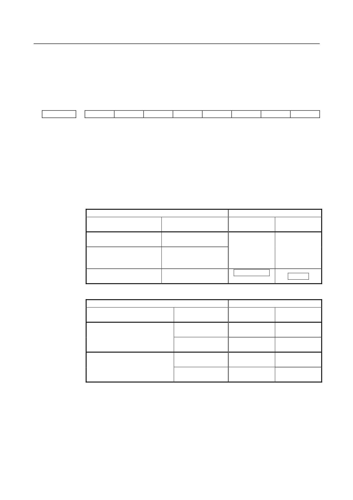
Direction of motor rotation
NOTE
When this parameter is set, the power must be turned off before
operation is continued.
[Input type] Parameter input
[Data type] Word axis
[Valid data range] -111,111
Set the direction of motor rotation.
If the motor turns clockwise when viewed from the pulse coder side, set 111. If the motor
turns counterclockwise when viewed from the pulse coder side, set -111.
Turned
Turned clockwise when
counterclockwise when
viewed from the pulse
FANUC
viewed from the pulse
coder: Set 111.
coder: Set -111.
2031
Torque command difference threshold of torque difference alarm
[Input type] Parameter input
[Data type] Word axis
[Valid data range] 0 to 14564
If the absolute value of the torque command difference between two axes exceeds the
value set in this parameter, an alarm is issued.
Set the same value for two axes that are placed under axis synchronous control.
The servo axis numbers of the synchronized master axis and slave axis must be assigned
so that an odd number is assigned to the master axis and the next axis number is assigned
to the slave axis. Examples are (1,2) and (3,4).
2087
Preload value for each axis (Tcmd offset)
[Input type] Parameter input
[Data type] Word axis
[Unit of data] (Ampere limit)/7282
[Valid data range] -1821 to 1821
An offset is applied to a torque command to suppress backlash.
Set a value much greater than the friction.
As a guideline, specify a value that is about one-third of the rated torque.
- 115 -
4.DESCRIPTION OF PARAMETERS
B-64310EN/02
[Example] To set a torque equivalent to 3 A in the opposite directions:
When the ampere limit is 40 A
3/(40/7282) = 546
Master side = 546
Slave side = -546
#7
#6
#5
#4
#3
#2
#1
#0
2282
ISE64x
[Input type] Parameter input
[Data type] Bit axis
#3
ISE64x To feed forward (bit 1 (FEED) of parameter No. 2005 is set to 1):
0: Normal feedrate limits are applied.
1: Extended feedrate limits are applied.
When feed forward is enabled, bit 7 of parameter No. 1013 is set to 1, and this parameter
is set for an axis, feedrate limits for the axis are extended as follows if the increment
system is IS-C, IS-D, or IS-E:
[Normal position control]
Functions used when Normal position control is used
Permissible feedrate
Detection unit:
Detection unit:
High-speed, high-precision
Feed forward
1μm
0.1μm
Not used/used (advanced
None
preview type)
IS-B:999m/min
IS-B:196m/min
advanced preview control
Not used/used (advanced
IS-C:999m/min
IS-C:999m/min
AI advanced preview control
preview type)
AI contour control
IS-B:240m/min
Electric gear box
Used (conventional type)
24m/min
IS-C:100m/min
[When spindle control with servo motor is used]
Functions used when Normal position control is used
Permissible feedrate
Feedrate limit
Detection unit:
Detection unit:
Extended permissible feedrate
multiplied by 10
1/1000deg
1/10000deg
Disabled
IS-B:2777min-1
IS-B:2777min-1
Disabled
(No.1408#3=0)
IS-C: 277min-1
IS-C: 277min-1
(No.1013#7=0)
Enabled
IS-B:27777min-1
IS-B:27777min-1
(No.1408#3=1)
IS-C: 2777min-1
IS-C: 2777min-1
Disabled
IS-B:2777min-1
IS-B:2777min-1
Enabled
(No.1408#3=0)
IS-C: 277min-1
IS-C: 277min-1
(No.1013#7=1)
Enabled
IS-B:27777min-1
IS-B:27777min-1
(No.2282#3=1)
(No.1408#3=1)
IS-C: 27777min-1
IS-C: 2777min-1
(*1) The values enclosed by a rectangle in the table are limits imposed by internal
processing of the servo software. As CMR is increased to make the detection unit
smaller, the permissible feedrate limited by the internal processing of the servo
software lowers in proportion to the detection unit (when a detection unit of 0.1 μm
is changed to 0.05μm, the permissible feedrate is halved).
(*2) In a semi-closed loop system using a high-resolution detector (a rotary motor or
linear motor), use of nano interpolation allows the maximum resolution of the
detector to be used for position control without using a smaller detection unit.
- 116 -
B-64310EN/02
4.DESCRIPTION OF PARAMETERS
(*3) Even when a large detection unit is to be used because the feedrate is limited by
detection unit as mentioned above, feedrate feedback data that significantly affects
velocity loop control is controlled by using a maximum resolution of the detector.
- 117 -

4.DESCRIPTION OF PARAMETERS
B-64310EN/02
4.17 PARAMETERS OF DI/DO (1 OF 2)
#7
#6
#5
#4
#3
#2
#1
#0
3001
MHI
RWM
[Input type] Parameter input
[Data type] Bit path
#2 RWM While a program in the program memory is being searched for, the rewind signal (RWD)
is:
0: Not output.
1: Output.
#7 MHI Exchange of strobe and completion signals for the M, S, T, and B
0: Normal
1: High-speed
#7
#6
#5
#4
#3
#2
#1
#0
3002
IOV
MFD
CHM
[Input type] Parameter input
[Data type] Bit path
#0 CHM For high-speed M/S/T/B, the distribution end signal DEN <Fn001.3> and an auxiliary
function code signal M00 to M31 <Fn010 to Fn013> are:
0: Not turned off even upon completion of the execution of the auxiliary function.
1: Turned off upon completion of the execution of the auxiliary function.
#2 MFD When the high-speed M/S/T/B interface is used, if a block specifying an M, S, T, or B
code does not contain a move command or dwell command, the distribution end signal
(DEN) and the strobe signal (MF, SF, TF, or BF) for the function are:
0: Output conventionally (the output of the distribution end signal is delayed).
1: Output at the same time.
#4 IOV Override-related signal logic is:
0: Used without modification
(A signal of negative logic is used as a negative logic signal, and a signal of positive
logic is used as a positive logic signal.)
1: Inverted
(A signal of negative logic is used as a positive logic signal, and a signal of positive
logic is used as a negative logic signal.)
The signals indicated below are affected.
Signal of negative logic:
• Feedrate override signals *FV0 to *FV7<G0012>
• Feedrate override signals (for PMC axis control)
*EFOV0g to *EFOV7g<G0151/G0163/G0175/G0187>
• Software operator’s panel signals *FV0O to *FV7O<F0078>
Signals of positive logic:
• Rapid traverse override signals ROV1,ROV2<G0014.0, 1>
• Software operator’s panel signals ROV1O,ROV2O<F0076.4,
>
• Rapid traverse override signals (for PMC axis control)
EROV1g,EROV2g<G0150.0, 1, G0162.0, 1, G0174.0, 1, G0186.0, 1>
- 118 -
B-64310EN/02
4.DESCRIPTION OF PARAMETERS
#7
#6
#5
#4
#3
#2
#1
#0
MVG
DEC
DAU
DIT
ITX
ITL
3003
DEC
DIT
ITX
ITL
[Input type] Parameter input
[Data type] Bit path
#0 ITL Interlock signal for all axes
0: Enabled
1: Disabled
#2 ITX Interlock signals for each axis
0: Enabled
1: Disabled
#3 DIT The interlock signal for each axis direction is:
0: Valid.
1: Invalid.
#4 DAU When bit 3 (DIT) of parameter No. 3003 is set to 0, the interlock signal for each axis
direction is:
0: Valid only in manual operation, and invalid in automatic operation.
1: Valid in either manual operation or automatic operation.
#5 DEC Deceleration signal (*DEC1 to *DEC5) for reference position return
0: Deceleration is applied when the signal is 0.
1: Deceleration is applied when the signal is 1.
#7 MVG During drawing with the dynamic graphic display function, the axis movement signal is:
0: Output.
1: Not output.
#7
#6
#5
#4
#3
#2
#1
#0
3004
OTH
BCY
BSL
[Input type] Parameter input
[Data type] Bit path
#0 BSL The block start interlock signal (*BSL) and cutting block start interlock signal (*CSL)
are:
0: Disabled.
1: Enabled.
#1 BCY When more than one operation is performed by one block command such as a canned
cycle, the block start interlock signal (*BSL) is:
0: Checked only at the beginning of the first cycle.
1: Checked at the beginning of every cycle.
#5 OTH The overtravel limit signal is:
0: Checked
1: Not checked
- 119 -
4.DESCRIPTION OF PARAMETERS
B-64310EN/02
WARNING
For safety, usually set 0 to check the overtravel limit signal.
#7
#6
#5
#4
#3
#2
#1
#0
3006
WPS
EP2
EPS
EPN
GDC
[Input type] Parameter input
[Data type] Bit
#0 GDC As the deceleration signal for reference position return:
0: X0009 is used.
1: G0196 is used. (X0009 is disabled.)
#1 EPN In external workpiece number search, signals for workpiece number specification are
selected.
The following signal selections are made by combining this parameter with bit 3 (EP2) of
parameter No. 3006:
EPN
Signals
The external workpiece search signals (PN1 to PN16) are used. (A number from 1
0
to 31 can be specified.)
The extended external workpiece number search signals (EPN0 to EPN13) are
1
used. (A number from 1 to 9999 can be specified.)
#2 EPS As the signal for starting external workpiece number search:
0: The automatic operation start signal ST is used. When automatic operation (memory
operation) is started, a search is made.
1: The external workpiece number search start signal EPNS is used. ST does not start a
search.
#6 WPS Each axis workpiece coordinate system preset signal:
0: Disabled.
1: Enabled.
#7
#6
#5
#4
#3
#2
#1
#0
3008
XSG
[Input type] Parameter input
[Data type] Bit path
NOTE
When this parameter is set, the power must be turned off before
operation is continued.
#2 XSG A signal assigned to an X address is:
0: Fixed at the address.
1: Able to be reassigned to an arbitrary X address.
- 120 -
B-64310EN/02
4.DESCRIPTION OF PARAMETERS
NOTE
When this parameter is set to 1, set parameter No. 3013, No. 3014,
No. 3012, and No. 3019. If parameter No. 3013 and No. 3014 are
not set, the deceleration signal for reference position return is
assigned to bit 0 of X0000. If parameter No. 3012 and No. 3019 are
not set, the skip signal, the PMC axis control skip signal, the
measurement position arrival signal, the interlock signal for each
axis direction, and the tool compensation value write signal are
assigned to X0000.
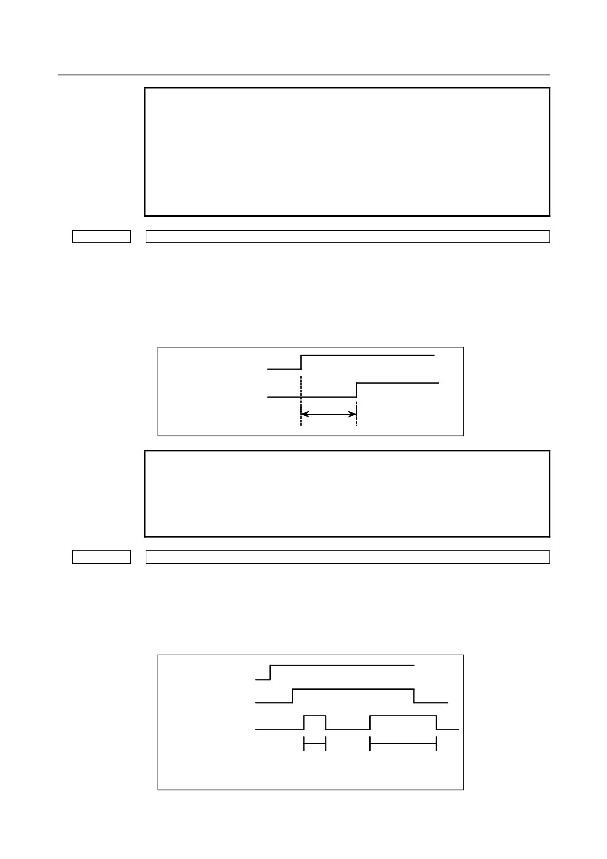
3010
Time lag in strobe signals MF, SF, TF, and BF
[Input type] Parameter input
[Data type] Word path
[Unit of data] msec
[Valid data range] 0 to 32767
The time required to send strobe signals MF, SF, TF, and BF after the M, S, T, and B
codes are sent, respectively.
M, S, T, B code
MF, SF, TF, BF signal
Delay time
NOTE
The time is counted in units of 8 ms. If the set value is not a
multiple of four, it is raised to the next multiple of four
Example
When 30 is set, 32 ms is assumed.
When 0 is set, 8 ms is assumed.
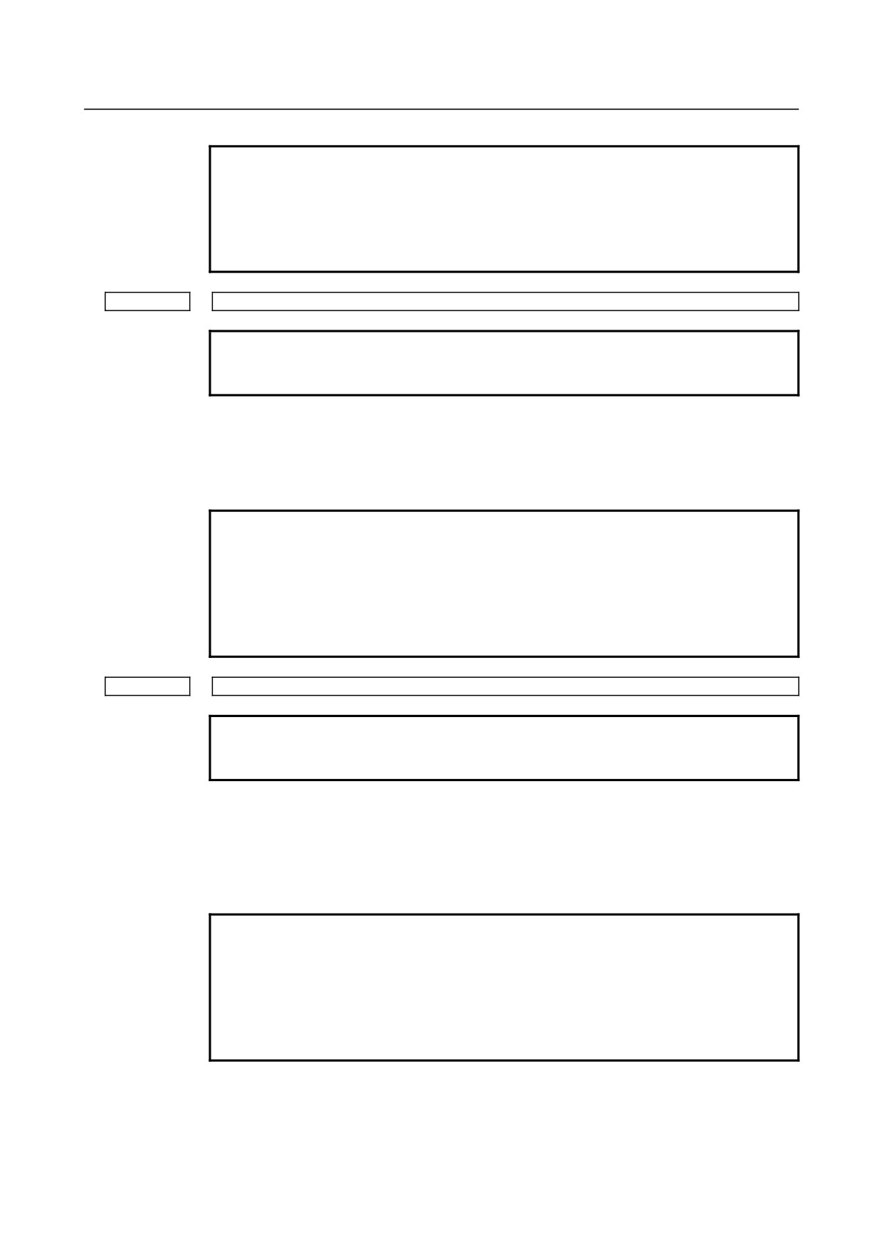
3011
Acceptable width of M, S, T, and B function completion signal (FIN)
[Input type] Parameter input
[Data type] Word path
[Unit of data] msec
[Valid data range] 0 to 32767
Set the minimum signal width of the valid M, S, T, and B function completion signal
(FIN).
M, S, T, B code
MF, SF, TF, BF signal
FIN sigal
Ignored because shorter
Valid because longer
than min. signal width
than min. signal width
- 121 -
4.DESCRIPTION OF PARAMETERS
B-64310EN/02
NOTE
The time is counted in units of 8 ms. If the set value is not a
multiple of four, it is raised to the next multiple of four
Example
When 30 is set, 32 ms is assumed.
When 0 is set, 8 ms is assumed.
3012
Skip signal assignment address
NOTE
When this parameter is set, the power must be turned off before
operation is continued.
[Input type] Parameter input
[Data type] Word path
[Valid data range] 0 to 327
Set an X address to which the skip signal (SKIPn) is to be assigned.
NOTE
This parameter is valid when bit 2 (XSG) of parameter No. 3008 is
set to 1.
The X addresses that can be actually used are shown below, but
they depend on the configuration of I/O Link point count expansion
options.
X0 to X127, X200 to X327
3013
X address to which the deceleration signal for reference position return is assigned
NOTE
When this parameter is set, the power must be turned off before
operation is continued.
[Input type] Parameter input
[Data type] Word axis
[Valid data range] 0 to 327
Set an address to which the deceleration signal (*DECn) for reference position return for
each axis is to be assigned.
NOTE
This parameter is valid when bit 2 (XSG) of parameter No. 3008 is
set to 1.
The X addresses that can be actually used are shown below, but
they depend on the configuration of I/O Link point count expansion
options.
X0 to X127, X200 to X327
- 122 -
B-64310EN/02
4.DESCRIPTION OF PARAMETERS
3014
Bit position of an X address to which the deceleration signal for reference position return is assigned
NOTE
When this parameter is set, the power must be turned off before
operation is continued.
[Input type] Parameter input
[Data type] Byte axis
[Valid data range] 0 to 7
Set a bit position to which the deceleration signal for reference position return (*DECn)
for each axis is to be assigned.
NOTE
This parameter is valid when bit 2 (XSG) of parameter No. 3008 is
set to 1.
3017
Output time of reset signal RST
[Input type] Parameter input
[Data type] Word path
[Unit of data] 16msec
[Valid data range] 0 to 255
When the output time of the reset signal RST is to be extended, set an extended time.
(RST signal output time) =
(Time required for reset processing) + (Parameter setting) × 16 msec
Address to which the PMC axis control skip signal and the measurement position arrival signal are
3019
assigned
NOTE
When this parameter is set, the power must be turned off before
operation is continued.
[Input type] Parameter input
[Data type] Word path
[Valid data range] 0 to 327
Sets addresses to which X address PMC axis control skip signal ESKIP, measurement
position arrival signals
(XAE1, XAE2, and XAE3 (M series); XAE1 and XAE2 (T
series)), and tool compensation write signals (±MIT1 and ±MIT2 (T series)) are allocated.
Example 1. When No.3012 is set to 5 and No.3019 is set to 6
When XSG (bit 2 of parameter No. 3008) is 1, the PMC axis control skip signal, and
measurement position arrival signal are allocated to X0006 and the skip signal is
allocated to X0005.
#7
#6
#5
#4
#3
#2
#1
#0
X005
SKIP
SKIP6
SKIP5
SKIP4
SKIP3
SKIP2
SKIP8
SKIP7
(T series)
#7
#6
#5
#4
#3
#2
#1
#0
SKIP
SKIP6
SKIP5
SKIP4
SKIP3
SKIP2
SKIP8
SKIP7
(M series)
- 123 -
4.DESCRIPTION OF PARAMETERS
B-64310EN/02
#7
#6
#5
#4
#3
#2
#1
#0
X006
ESKIP
-MIT2
+MIT2
-MIT1
+MIT1
XAE2
XAE1
(T series)
#7
#6
#5
#4
#3
#2
#1
#0
ESKIP
XAE3
XAE2
XAE1
(M series)
Example 2. When No.3012 is set to 5 and No.3019 is set to 5
When XSG (bit 2 of parameter No. 3008) is 1, the PMC axis control skip signal,
measurement position arrival signal, and skip signal are allocated to X0005.
#7
#6
#5
#4
#3
#2
#1
#0
ESKIP
-MIT2
+MIT2
-MIT1
+MIT1
XAE2
XAE1
X005
SKIP
(T series)
SKIP6
SKIP5
SKIP4
SKIP3
SKIP2
SKIP8
SKIP7
#7
#6
#5
#4
#3
#2
#1
#0
ESKIP
XAE3
XAE2
XAE1
SKIP
SKIP5
SKIP4
SKIP3
(M series)
SKIP6
SKIP2
SKIP8
SKIP7
NOTE
This parameter is valid when bit 2 (XSG) of parameter No. 3008 is
set to 1.
The X addresses that can be actually used are shown below, but
they depend on the configuration of I/O Link point count expansion
options.
X0 to X127, X200 to X327
3030
Allowable number of digits for the M code
3031
Allowable number of digits for the S code
3032
Allowable number of digits for the T code
[Input type] Parameter input
[Data type] Byte path
[Valid data range] 1 to 8
Set the allowable numbers of digits for the M, S, and T codes.
When 0 is set, the allowable number of digits is assumed to be 8.
NOTE
Up to 5 digits can be specified in the S code.
3033
Allowable number of digits for the B code (second auxiliary function)
[Input type] Parameter input
[Data type] Byte path
[Valid data range] 1 to 8
Set the allowable number of digits for the second auxiliary function.
When 0 is set, the allowable number of digits is assumed to be 8.
To enable a decimal point to be specified, bit 0 (AUP) of parameter No. 3450 must be set
to 1. In this case, the allowable number of digits set in this parameter includes the number
of decimal places.
If a value exceeding the allowable number of digits is specified, the alarm (PS0003) is
issued.
- 124 -
B-64310EN/02
4.DESCRIPTION OF PARAMETERS
4.18 PARAMETERS OF DISPLAY AND EDIT (1 OF 5)
#7
#6
#5
#4
#3
#2
#1
#0
SBA
KBF
3101
KBF
[Input type] Parameter input
[Data type] Bit
#1 KBF When the screen or mode is changed, the contents of the key-in buffer are:
0: Cleared.
1: Not cleared.
#7 SBA In 2-path control, the current position display order on the current position display screen
is:
0: Path 1 followed by path 2.
1: Path 2 followed by path 1.
#7
#6
#5
#4
#3
#2
#1
#0
DIP
3103
[Input type] Parameter input
[Data type] Bit
#1 DIP In 2-path control, the current position display screen displays:
0: Two paths regardless of path selection signal HEAD<G0063.0>.
1: The path selected by path selection signal HEAD<G0063.0>.
NOTE
It is necessary to set 1 to bit 4 (9DE) of parameter No.11350 to
display the current position for 2-path by DIP=0.
#7
#6
#5
#4
#3
#2
#1
#0
DAC
DRC
PPD
MCN
3104
DAC
DAL
DRC
DRL
PPD
MCN
[Input type] Parameter input
[Data type] Bit path
#0 MCN Machine position
0: Regardless of whether input is made in mm or inches, the machine position
is
displayed in mm for millimeter machines, or in inches for inch machines.
1: When input is made in mm, the machine position is displayed in mm, and when
input is made in inches, the machine position is displayed in inches accordingly.
#3 PPD Relative position display when a coordinate system is set
0: Not preset
1: Preset
- 125 -

4.DESCRIPTION OF PARAMETERS
B-64310EN/02
NOTE
If any of the following is executed when PPD is set to 1, the relative
position display is preset to the same value as the absolute position
display:
(1) Manual reference position return
(2) Coordinate system setting based on G92 (G50 for G code
system A on the lathe system)
(3) Workpiece coordinate system presetting based on G92.1
(G50.3 for G code system A on the lath system)
(4) When a T code for the T series is specified.
#4 DRL Relative position
0: The actual position displayed takes into account tool length offset.
1: The programmed position displayed does not take into account tool length offset.
NOTE
In the T series, whether to exclude a tool offset when displaying the
relative position is determined by the setting of bit 0 (DRP) of
parameter No. 3129.
#5 DRC When relative positions are displayed:
0: Values not excluding the amount of travel based on cutter compensation and tool
nose radius compensation are displayed.
1: Values excluding the amount of travel based on cutter compensation and tool nose
radius compensation (programmed positions) are displayed.
#6 DAL Absolute position
0: The actual position displayed takes into account tool length offset.
1: The programmed position displayed does not take into account tool length offset.
NOTE
In T series, whether to exclude a tool offset when displaying the
absolute position is determined by the setting of bit 1 (DAP) of
parameter No. 3129.
#7 DAC When an absolute position are displayed:
0: Values not excluding the amount of travel based on cutter compensation and tool
nose radius compensation are displayed.
1: Values excluding the amount of travel based on cutter compensation and tool nose
radius compensation (programmed positions) are displayed.
#7
#6
#5
#4
#3
#2
#1
#0
3105
DPS
PCF
DPF
[Input type] Parameter input
[Data type] Bit path
#0 DPF The actual speed is:
0: Not displayed
1: Displayed
- 126 -
B-64310EN/02
4.DESCRIPTION OF PARAMETERS
#1 PCF Addition of the movement of the PMC-controlled axes to the actual speed display
0: Added
1: Not added
#2 DPS The actual spindle speed and T code are:
0: Not displayed
1: Displayed
#7
#6
#5
#4
#3
#2
#1
#0
SOV
OPH
DHD
3106
SOV
OPH
[Input type] Setting input
[Data type] Bit
#0 DHD On the program screen:
0: Only a selected path can be edited and displayed.
1:
2-path can be edited and displayed at the same time.
#4 OPH The operation history screen is:
0: Not displayed.
1: Displayed.
#5 SOV A spindle override value is:
0: Not displayed.
1: Displayed.
NOTE
This parameter is valid only when bit 2 (DPS) of parameter No.
3105 is set o 1.
#7
#6
#5
#4
#3
#2
#1
#0
3107
MDL
SOR
GSC
[Input type] Setting input
[Data type] Bit path
#3 GSC The feedrate to be displayed is:
0: Feedrate per minute.
1: Determined by bit 5 (FSS) of parameter No. 3191.
#4 SOR Display of the program directory
0: Programs are listed in the order of registration.
1: Programs are listed in the order of name.
#7 MDL The modal state on the program(MDI) screen of the 8.4 inch screen is:
0: Not displayed.
1: Displayed.
#7
#6
#5
#4
#3
#2
#1
#0
3108
JSP
SLM
WCI
PCT
[Input type] Parameter input
[Data type] Bit path
- 127 -
4.DESCRIPTION OF PARAMETERS
B-64310EN/02
#2 PCT For modal T display on the program check screen:
0: A specified T value is displayed.
1: HD.T and NX.T are displayed.
#4 WCI On the workpiece coordinate system screen, a counter input is:
0: Disabled.
1: Enabled.
#6 SLM The spindle load meter is:
0: Not displayed.
1: Displayed.
NOTE
1 This parameter is valid only when bit 2 (DPS) of parameter No.
3105 is set to 1.
2 This parameter is valid only for serial spindles.
#7 JSP On the current position display screen and program check screen, jog feed is:
0: Not displayed.
1: Displayed.
In manual operation mode, the jog feedrate is displayed. In automatic operation mode, the
dry run feedrate is displayed. In each case, the feedrate to which a manual feedrate
override has been applied is displayed.
#7
#6
#5
#4
#3
#2
#1
#0
3109
IKY
DWT
[Input type] Parameter input
[Data type] Bit path
#1 DWT Characters G and W in the display of tool wear/geometry compensation amount
0: The characters are displayed at the left of each number.
1: The characters are not displayed.
#2 IKY On the tool offset screen and workpiece shift screen (T series), soft key [INPUT] is:
0: Displayed.
1: Not displayed.
#7
#6
#5
#4
#3
#2
#1
#0
3111
NPA
OPS
OPM
SVP
SPS
SVS
[Input type] Setting input
[Data type] Bit path
#0 SVS The soft key for displaying the servo setting screen is:
0: Not displayed.
1: Displayed.
#1 SPS The soft key for displaying the spindle setting screen is:
0: Not displayed.
1: Displayed.
- 128 -
B-64310EN/02
4.DESCRIPTION OF PARAMETERS
#2 SVP Spindle synchronization errors displayed on the spindle tuning screen
0: Instantaneous values are displayed.
1: Peak-hold values are displayed.
Spindle synchronization errors are displayed on the side of the spindle that functions as a
slave axis in spindle synchronization control.
#5 OPM Operating monitor
0: Not displayed
1: Displayed
#6 OPS The speedometer on the operating monitor screen indicates:
0: Spindle motor speed
1: Spindle speed
#7 NPA Action taken when an alarm is generated or when an operator message is entered
0: The display shifts to the alarm or message screen.
1: The display does not shift to the alarm or message screen.
NOTE
When MANUAL GUIDE i is provided, bit 7 (NPA) of parameter No.
3111 must be set to 0. (If this bit is set to 1, a warning message is
issued at power-on.)
#7
#6
#5
#4
#3
#2
#1
#0
3112
EAH
OMH
[Input type] Parameter input
[Data type] Bit
#2 OMH The external operator message history screen is:
0: Not displayed.
1: Displayed.
#3 EAH Messages of the external alarm/macro alarm in alarm or operation history:
0: Not recorded
1: Recorded
NOTE
This parameter is valid when bit 7 (HAL) of parameter No. 3196 is
set to 0.
#7
#6
#5
#4
#3
#2
#1
#0
3113
MS1
MS0
DCL
HMC
[Input type] Parameter input
[Data type] Bit
#0 HMC The contents of the external operator message history:
0: Cannot be erased.
1: Can be erased.
#5 DCL The touch panel compensation screen is:
0: Disabled.
1: Enabled.
- 129 -
4.DESCRIPTION OF PARAMETERS
B-64310EN/02
Set this parameter to 0 usually. Touch panel compensation becomes necessary only when
the panel is replaced or memory all clear operation is performed. Set this parameter to 1
only when performing touch panel compensation. Upon completion of compensation, set
this parameter to 0.
#6
MS0
#7
MS1 Set the combination of the number of characters and the number of messages to be
preserved in the external operator message history.
Parameter
Maximum number of characters
Number of messages
MS1=0
MS0=0
255
8
MS1=0
MS0=1
200
10
MS1=1
MS0=0
100
18
MS1=1
MS0=1
50
32
NOTE
1 Although up to 255 characters can be specified for each external
operator message, you can use the combination of bits 6 (MS0)
and 7 (MS1) of parameter No. 3113 to limit the number of
characters and select the number of messages to be preserved in
the external operator message history.
2 The settings of bits 6 (MS0) and 7 (MS1) of parameter No. 3113
take effect the next time the power is turned on. The external
operator message history is erased at that time.
3 Even though you change the settings of bits 6 (MS0) and 7 (MS1)
of parameter No. 3113, the alarm PW0000, "POWER MUST BE
OFF" is not issued. You must however turn on the power again
before the new settings can take effect.
4 If text (such as single-byte katakana or kanji characters) is entered
in character code, the number of characters recorded in the
external operator message history may be smaller than the
maximum number of characters set by bits 6 (MS0) and 7 (MS1) of
parameter No. 3113.
#7
#6
#5
#4
#3
#2
#1
#0
3114
ICU
IGR
IMS
ISY
IOF
IPR
IPO
[Input type] Parameter input
[Data type] Bit
#0 IPO When the
function key is pressed while the position display screen is being
displayed:
0: The screen is changed.
1: The screen is not changed.
#1 IPR When the
function key is pressed while the program screen is being displayed:
0: The screen is changed.
1: The screen is not changed.
- 130 -
B-64310EN/02
4.DESCRIPTION OF PARAMETERS
#2 IOF When the
function key is pressed while the offset/setting screen is being
displayed:
0: The screen is changed.
1: The screen is not changed.
#3 ISY When the
function key is pressed while the system screen is being displayed:
0: The screen is changed.
1: The screen is not changed.
#4 IMS When the
function key is pressed while the message screen is being displayed:
0: The screen is changed.
1: The screen is not changed.
#5 IGR When the
function key is pressed while the custom or graphic screen is being
displayed:
0: The screen is changed.
1: The screen is not changed.
#6 ICU When the
function key is pressed while the custom screen is being displayed:
0: The screen is changed.
1: The screen is not changed.
#7
#6
#5
#4
#3
#2
#1
#0
3115
NDFx
NDAx
NDPx
[Input type] Parameter input
[Data type] Bit axis
#0 NDPx The current position is:
0: Displayed.
1: Not displayed.
NOTE
When using the electric gear box (EGB) function (M series), set 1
for the EGB dummy axis to disable current position display.
#1 NDAx The current position and the amount of the movement to be made in absolute and relative
coordinates are:
0: Displayed.
1: Not displayed.
#3 NDFx In calculation for actual cutting feedrate display, the feedrate of a selected axis is:
0: Considered.
1: Not considered.
#7
#6
#5
#4
#3
#2
#1
#0
3116
MDC
T8D
PWR
[Input type] Setting input
[Data type] Bit path
- 131 -

4.DESCRIPTION OF PARAMETERS
B-64310EN/02
#2 PWR Alarm SW0100 (parameter write enabled), which is issued when bit 0 (PWE) of setting
parameter No. 8900 is set to 1, is cleared by:
0: "CAN" + "RESET".
1: "RESET" or turning on the external reset.
#6 T8D The number of digits of a T code is:
0:
4.
1:
8.
#7 MDC Maintenance information data:
0: Cannot be erased entirely.
1: Can be erased entirely.
#7
#6
#5
#4
#3
#2
#1
#0
3117
SPP
SMS
[Input type] Parameter input
[Data type] Bit path
#0 SMS On the program check screen of the 8.4-inch display unit, the function for displaying the
spindle load meter and spindle speed meter in the remaining movement amount display
position and modal information display position is:
0: Disabled.
1: Enabled.
#1 SPP When a serial spindle is used, the position coder signal pulse data based on the
one-rotation signal is:
0: Not displayed on diagnosis screen No. 445.
1: Displayed on diagnosis screen No. 445.
NOTE
1 For a spindle not connected, 0 is indicated.
2 To display this data, the following conditions must be met:
<1>FANUC's α spindle amplifier and serial spindle are used.
<2>The serial spindle detects the one-rotation signal.
To detect the one-rotation signal accurately, spindle orientation
must be performed. This operation must be performed just once
after the power is turned on and is not needed subsequently.
To determine whether the one-rotation signal has been detected or
not, check the serial spindle status signals (PC1DEA to PC1DED).
#7
#6
#5
#4
#3
#2
#1
#0
3119
TPA
DDS
[Input type] Parameter input
[Data type] Bit
NOTE
When at least one of these parameters is set, the power must be
turned off before operation is continued.
- 132 -
B-64310EN/02
4.DESCRIPTION OF PARAMETERS
#2 DDS The touch panel is:
0: Enabled.
1: Disabled.
Set this parameter to 1 when disabling the touch panel temporarily, for example, at
start-up time.
#3 TPA When the option for the external touch panel interface is selected, the external touch
panel interface connection is:
0: Valid.
1: Invalid.
For an external touch panel (called ETP hereinafter), the RS-232C serial port 2 ((JD36A
or JD54) on the main board of the CNC is used.
When using ETP, set bit 3 (TPA) of parameter No. 3119 to 0.
By this setting, JD36A or JD54 is used for ETP, regardless of the setting of I/O
CHANNEL(I/O device selection)of the existing parameters Nos. 0021 through 0023.
For other I/O devices, use JD56A and so forth.
By the setting above, the settings of the existing parameters Nos. 0100 and 0121 through
0123 become invalid for channel 2 (JD36A or JD54), and the following settings are
applied at all times:
- Baud rate
:
19200 bps
- Stop bit
:
1 bit
- Parity check
:
Even parity
3122
Time interval used to record time data in operation history
[Input type] Parameter input
[Data type] Word path
[Unit of data] min
[Valid data range] 0 to 1440
When history data is recorded within a set time period, the time for each set time period is
recorded in the history data.
When 0 is set, the specification of a time period of 10 minutes is assumed.
NOTE
It is necessary to set the same value in this parameter with both
paths for 2-path system.
3123
Time required before a screen saver is activated
[Input type] Setting input
[Data type] Byte path
[Unit of data] min
[Valid data range] 0 to 127
After a time (in minutes) set in parameter No. 3123 passes without key operation, the NC
screen is erased automatically. Pressing a key causes the NC screen to reappear.
NOTE
1 Setting 0 disables automatic screen erasure.
2 This function cannot be used together with manual screen erasure.
If 1 or a larger value is set in this parameter, manual screen
erasure is disabled.
- 133 -
4.DESCRIPTION OF PARAMETERS
B-64310EN/02
#7
#6
#5
#4
#3
#2
#1
#0
3124
D08
D07
D06
D05
D04
D03
D02
D01
#7
#6
#5
#4
#3
#2
#1
#0
3125
D16
D15
D14
D13
D12
D11
D10
D09
#7
#6
#5
#4
#3
#2
#1
#0
3126
D24
D23
D22
D21
D20
D19
D18
D17
#7
#6
#5
#4
#3
#2
#1
#0
3127
D32
D31
D30
D29
D28
D27
D26
D25
[Input type] Parameter input
[Data type] Bit path
D01 to D32
Set a group of G codes to be displayed on the program check screen.
The table below indicates the correspondence between bits and G code groups.
The setting of a bit has the following meaning:
0: Displays the G code group corresponding to a bit.
1: Does not display the G code group corresponding to a bit.
Parameter
G code group
D01
01
D02
02
D03
03
:
:
D32
32
3128
Retracement time for deleting alarm data from the alarm history
[Input type] Parameter input
[Data type] Word path
[Unit of data] sec
[Valid data range] 0 to 255
From the alarm history, the alarm data that occurred during a set period of time back from
the power-off time is deleted.
When 0 is set, a retracement time of 1 second is assumed to be specified.
#7
#6
#5
#4
#3
#2
#1
#0
MRE
DAP
DRP
3129
MRE
[Input type] Parameter input
[Data type] Bit path
#0 DRP For relative position display:
0: The actual position considering a tool offset (tool movement) is displayed.
1: The programmed position excluding a tool offset (tool movement) is displayed.
- 134 -
B-64310EN/02
4.DESCRIPTION OF PARAMETERS
NOTE
In the M series, whether to exclude tool length compensation when
displaying the relative position is determined by bit 4 (DRL) of
parameter No. 3104.
#1 DAP For absolute position display:
0: The actual position considering a tool offset (tool movement) is displayed.
1: The programmed position excluding a tool offset (tool movement) is displayed.
NOTE
In M series, whether to exclude the tool length offset when
displaying the absolute position is determined according to the
setting of bit 6 (DAL) of parameter No. 3104.
#2 MRE When mirror image is used, relative coordinates are:
0: Updated with respect to the machine coordinates.
1: Updated with respect to the absolute coordinates.
Set this parameter to 1 when handling relative coordinates in the same way as for the T
series of the FS0i-C.
3130
Axis display order for current position display screens
[Input type] Parameter input
[Data type] Byte axis
[Valid data range] 0 to Number of controlled axes
Set the order in which axes are displayed on current position display screens (absolute,
relative overall, and handle interrupt screens).
3131
Subscript of axis name
[Input type] Parameter input
[Data type] Byte axis
[Valid data range] 0 to 9, 32, 65 to 90
In order to distinguish axes under parallel operation, synchronization control, and tandem
control, specify a subscript for each axis name.
Setting value
Meaning
Each axis is set as an axis other than a synchronization control axis and
0
tandem control axis.
1 to 9
A set value is used as a subscript.
65 to 90
A set letter (ASCII code) is used as a subscript.
[Example] When the axis name is X, a subscript is added as indicated below.
Setting value
Axis name displayed on a screen such as the position display screen
0
X
1
X1
77
XM
83
XS
- 135 -

4.DESCRIPTION OF PARAMETERS
B-64310EN/02
When the subscription of an axis name is not set in a 2-path system, the subscription of an
axis name is automatically set to the path number. To hide the subscription of an axis
name, set the parameter of the subscription of an axis name to the ASCII code (32) of a
space.
3132
Axis name (absolute coordinate) for current position display
[Input type] Parameter input
[Data type] Byte axis
[Valid data range] 0 to 255
These parameters set the axis name for current position display.
When G code system B or C is used, the axis name set in parameter No.3132 is used for
both absolute and relative coordinate axes.
The values set in these parameters are used only for display.
When 0 is set in this parameter, the setting of parameter No. 1020 is used.
3133
Axis name (relative coordinate) for current position display
[Input type] Parameter input
[Data type] Byte axis
[Valid data range] 0 to 255
These parameters set the axis name for current position display.
When G code system B or C is used, the axis name set in parameter No.3132 is used for
both absolute and relative coordinate axes.
The values set in these parameters are used only for display.
When 0 is set in this parameter, the setting of parameter No. 1020 is used.
Data display order of each axis on the workpiece coordinate system setting screen and workpiece
3134
coordinate system shift amount setting screen
[Input type] Parameter input
[Data type] Byte axis
[Valid data range] 0 to Number of controlled axes
Set the data display order of each axis on the workpiece coordinate system setting screen
(M series/T series) and workpiece coordinate system shift amount setting screen (T
series).
No data is displayed for an axis with 0 set in this parameter.
3135
Number of decimal places in actual feedrate display
[Input type] Setting input
[Data type] Byte path
[Valid data range] 0 to 3
Set the number of decimal places in actual feedrate display.
In the case of inch input, the number of decimal places is a set value plus 2.
Setting value
0 : Metric input Displayed without a decimal point
Inch inputDisplayed using the second decimal place
1 : Metric input Displayed using the first decimal place
Inch inputDisplayed using the third decimal place
2 : Metric input Displayed using the second decimal place
Inch inputDisplayed using the fourth decimal place
3 : Metric input Displayed using the third decimal place
Inch inputDisplayed using the fifth decimal place
- 136 -
B-64310EN/02
4.DESCRIPTION OF PARAMETERS
3141
Path name (1st character)
3142
Path name (2nd character)
3143
Path name (3rd character)
3144
Path name (4th character)
3145
Path name (5th character)
3146
Path name (6th character)
3147
Path name (7th character)
[Input type] Parameter input
[Data type] Word path
[Valid data range] See the character-code correspondence table.
Specify a path name with codes.
Any character string consisting of alphanumeric characters, katakana characters, and
special characters with a maximum length of seven characters can be displayed as a series
name.
When 0 is set in parameter No. 3141, the path name is displayed according to the
following table.
Language to
Language to
Path name
Path name
display in CNC
display in CNC
English
HEAD1 (HEAD2)
Portuguese
CABEC.1 (CABEC.2))
Japanese
刃物台 1 (刃物台 2)
Polish
GLOWIC1 (GLOWIC2)
German
KANAL1 (KANAL2)
Hungarian
FEJ1 (FEJ2)
French
TETE1 (TETE2)
Swedish
HUVUD1 (HUVUD2)
Traditional
HEAD1 (HEAD2)
Czech
KANAL1 (KANAL2)
Chinese
Simplified Chinese
路径 1 (路径 2)
Russian
ПУТЬ1 (ПУТЬ2)
Italian
TEST1 (TEST2)
Turkish
HEAD1 (HEAD2)
Korean
HEAD1 (HEAD2)
Bulgarian
ГЛВА1 (ГЛВА2)
Spanish
CAB.1 (CAB.2)
Dutch
KAN.1 (KAN.2)
Danish
HOVED1 (HOVED2)
NOTE
For characters and codes, see Appendix A, “CHARACTER CODE
LIST”.
3160
Setting of MDI unit type
[Input type] Parameter input
[Data type] Byte
[Valid data range] 0 to 4
Set the type of an MDI unit when the type of an MDI unit is not automatically identified.
Setting value
Type
0
Depends on the system type and indicator type.
1
Standard MDI unit for the T series (lathe system)
- 137 -
4.DESCRIPTION OF PARAMETERS
B-64310EN/02
Setting value
Type
2
Standard MDI unit for the M series (machining center system)
3
Small MDI unit for the T series (lathe system)
4
Small MDI unit for the M series (machining center system)
When 0 is set in this parameter, the type of a MDI unit is determined as follows:
Type of path control
Type of indicator
Type
Standard MDI unit for the T
Type of 12 horizontal soft keys
series (lathe system)
T series
Small MDI unit for the T series
Type of 7 horizontal soft keys
(lathe system)
Standard MDI unit for the M
Type of 12 horizontal soft keys
series (machining center system)
M series
Small MDI unit for the M series
Type of 7 horizontal soft keys
(machining center system)
#7
#6
#5
#4
#3
#2
#1
#0
FSS
SSF
3191
FSS
SSF
WSI
[Input type] Parameter input
[Data type] Bit path
#2 WSI On the workpiece zero point offset screen, the soft key [INPUT] is:
0: Displayed.
1: Not displayed.
#3 SSF On the setting screen, the soft key for confirming data input is:
0: Not displayed.
1: Displayed.
#5 FSS Feedrate per minute and feedrate per revolution are:
0: Switched depends on the operation state.
1: Not switched depending on the operation state and feedrate per revolution is always
used.
NOTE
This parameter is valid when bit 3 (GSC) of parameter No. 3107 is
1.
#7
#6
#5
#4
#3
#2
#1
#0
PLD
TRA
T2P
3192
TRA
T2P
[Input type] Parameter input
[Data type] Bit
#1 T2P When more than one point is pressed on the touch panel:
0: The position at the center of gravity is obtained.
1: The point pressed first is obtained.
- 138 -
B-64310EN/02
4.DESCRIPTION OF PARAMETERS
NOTE
1 Even when bit parameter T2P is set to 1, the position at the center
of gravity is assumed to be pressed if two or more points are
pressed within a scan period (32 ms) of the touch panel.
2 If a C executer application or the like has a touch panel drag (move
in pressed state) function, set parameter T2P to 0.
#2 TRA If a point on the touch panel is kept pressed for a time specified in parameter No. 3197 or
longer,
0: An alarm is not raised.
1: An alarm (SR5303) is raised.
NOTE
If an C executer application or the like has a touch panel repeat
(continue pressing) function, set parameter TRA to 0.
#7 PLD On the screen of the 10.4-inch display unit where positional display is performed on the
left half, the function for displaying the servo axis load meter and spindle load meter is:
0: Disabled.
1: Enabled.
Parameters No.13140 and 13141 can be used to display up to two characters for the name
of each spindle. If this parameter is not set (this parameter is 0), the following names
are used.
First spindle
: S1
Second spindle
: S2
Third spindle
: S3
#7
#6
#5
#4
#3
#2
#1
#0
DOP
3193
[Input type] Parameter input
[Data type] Bit
#2 DOP In 2-path control, on the POSITION screen (absolute, relative, all, manual handle
interruption), PROGRAM CHECK screen, and ALARM screen, two paths' information
is:
0: Displayed at the same time.
1: Not displayed at the same time.
#7
#6
#5
#4
#3
#2
#1
#0
3195
EKE
HDE
HKE
CPR
[Input type] Parameter input
[Data type] Common to the bit system
#2 CPR Displaying of the parameter setting support screen by function key [SYSTEM] is:
0: Performed.
1: Not performed.
#5 HKE A key operation history is:
0: Recorded.
1: Not recorded.
- 139 -
4.DESCRIPTION OF PARAMETERS
B-64310EN/02
#6 HDE A DI/DO history is:
0: Recorded.
1: Not recorded.
#7 EKE The contents of operation history and alarm history
0: cannot be deleted.
1: can be deleted.
#7
#6
#5
#4
#3
#2
#1
#0
3196
HAL
HOM
HMV
HPM
HWO
HTO
[Input type] Parameter input
[Data type] Bit
#0 HTO A modification history of tool offset data is:
0: Not recorded.
1: Recorded.
#1 HWO A modification history of workpiece offset
data/extended
workpiece offset
data/workpiece shift (T series) is:
0: Not recorded.
1: Recorded.
#2 HPM A modification history of parameters is:
0: Not recorded.
1: Recorded.
#3 HMV A modification history of custom macro common variables is:
0: Not recorded.
1: Recorded.
#6 HOM The operation history is:
0: Recorded.
1: Not recorded.
#7 HAL When an alarm is issued, additional information (modal data, absolute coordinates, and
machine coordinates present at the issuance of the alarm) is:
0: Recorded in the operation history and alarm history.
1: Not recorded in the operation history and alarm history.
To record as many alarm history items as possible, rather than detailed alarm information,
set 1.
3197
Detection time of continuous pressing on touch panel
[Input type] Parameter input
[Data type] Word
[Unit of data] sec
[Valid data range] 0 to 255
Set a period of continuous pressing on the touch panel which causes alarm to be raised.
When 0 is set, it is equivalent to 20.
- 140 -
B-64310EN/02
4.DESCRIPTION OF PARAMETERS
NOTE
This parameter is valid when bit 2 (TRA) of parameter No. 3192 is
set to 1.
#7
#6
#5
#4
#3
#2
#1
#0
3201
NPE
N99
REP
RAL
RDL
[Input type] Parameter input
[Data type] Bit path
#0 RDL When a program is registered by input/output device external control
0: The new program is registered following the programs already registered.
1: All registered programs are deleted, then the new program is registered. Note that
programs which are protected from being edited are not deleted.
NOTE
Registered programs are placed in the background default folder
set in the program list screen. Before manipulating this signal, set
the default folder in the background correctly.
#1 RAL When programs are registered by external I/O device control:
0: All programs are registered.
1: Only one program is registered.
NOTE
Registered programs are placed in the background default folder
set in the program list screen. Before manipulating this signal, set
the default folder in the background correctly.
#2 REP Action in response to an attempt to register a program whose number is the same as that
of an existing program
0: An alarm is generated.
1: The existing program is deleted, then the new program is registered. Note that if the
existing program is protected from being edited, it is not deleted, and an alarm is
generated.
#5 N99 With an M99 block, when bit 6 (NPE) of parameter No.3201 = 0, program registration is
assumed to be:
0: Completed
1: Not completed
#6 NPE With an M02, M30, or M99 block, program registration is assumed to be:
0: Completed
1: Not completed
#7
#6
#5
#4
#3
#2
#1
#0
3202
PSR
NE9
OSR
NE8
[Input type] Parameter input
[Data type] Bit path
- 141 -

4.DESCRIPTION OF PARAMETERS
B-64310EN/02
#0 NE8 Editing of subprograms with program numbers 8000 to 8999
0: Not inhibited
1: Inhibited
When this parameter is set to 1, the following editing operations are disabled:
(1) Program deletion (Even when deletion of all programs is specified, programs with
program numbers 8000 to 8999 are not deleted.)
(2) Program output (Even when outputting all programs is specified, programs with
program numbers 8000 to 8999 are not output.)
(3) Program number search
(4) Program editing of registered programs
(5) Program registration
(6) Program collation
(7) Displaying programs
NOTE
This parameter setting does not affect the following programs:
(1) Programs on the Data Server
(2) Programs for running and editing memory card programs on a
memory card
#3 OSR Pressing the [O SEARCH] soft key without entering a program number with keys in a
program number search:
0: Searches for the next program number (order of registration).
1: Disables the search.
#4
NE9 Editing of subprograms with program numbers 9000 to 9999
0: Not inhibited
1: Inhibited
When this parameter is set to 1, the following editing operations are disabled:
(1) Program deletion (Even when deletion of all programs is specified, programs with
program numbers 9000 to 9999 are not deleted.)
(2) Program output (Even when outputting all programs is specified, programs with
program numbers 9000 to 9999 are not output.)
(3) Program number search
(4) Program editing of registered programs
(5) Program registration
(6) Program collation
(7) Displaying programs
NOTE
If this parameter is set, a protected program is also displayed.
#6
PSR Search for the program number of a protected program
0: Disabled
1: Enabled
NOTE
This parameter setting does not affect the following programs:
(1) Programs on the Data Server
(2) Programs for running and editing memory card programs on a
memory card
- 142 -