FANUC Series 0i-MODEL D, Series 0i Mate-MODEL D. PARAMETER MANUAL - page 8
B-64310EN/02
4.DESCRIPTION OF PARAMETERS
[Unit of data] mm, inch (input unit)
[Min. unit of data] Depend on the increment system of the reference axis
[Valid data range] 9 digit of minimum unit of data (refer to standard parameter setting table (A))
(When the increment system is IS-B, -999999.999 to +999999.999)
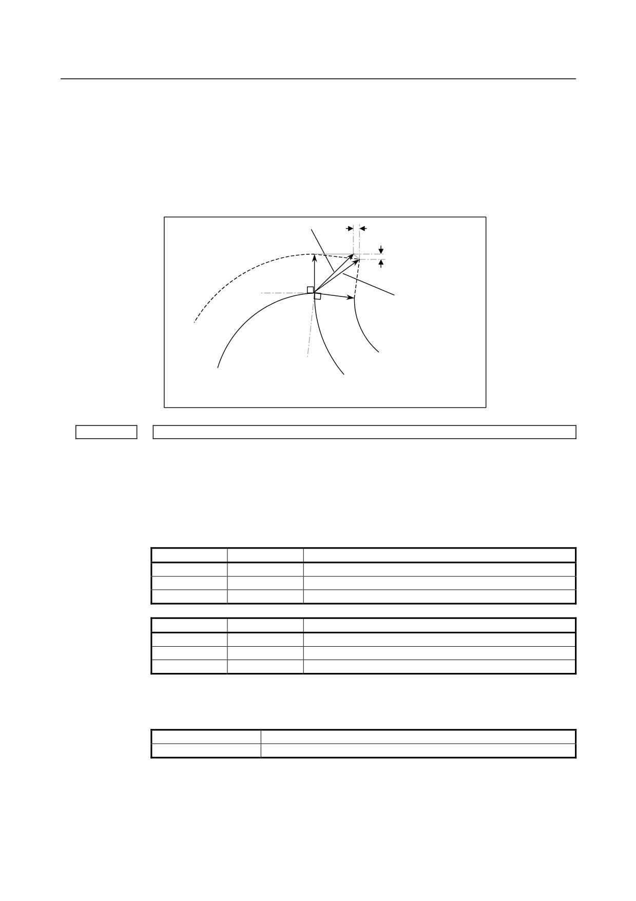
When the tool moves around a corner in cutter compensation or tool nose radius
compensation mode, the limit for ignoring the small travel amount resulting from
compensation is set. This limit eliminates the interruption of buffering caused by the
small travel amount generated at the corner and any change in feedrate due
to
the
interruption.
If ΔVx ≤ ΔVlimit and ΔVY≤ ΔVlimit,
ΔVx
this vector is ignored.
ΔVY
S
r
Even if ΔVx ≤ ΔVlimit and
ΔVY ≤ ΔVlimit, vector to
r
single-block stop point
Tool center path
remains.
N1
Programmed path
N2
ΔVlimit is determined depending on the setting in parameter No. 5010.
5013
Maximum value of tool wear compensation
[Input type] Parameter input
[Data type] Real path
[Unit of data] mm, inch (offset unit)
[Min. unit of data] The increment system of a tool offset value is followed.
[Valid data range] The settings of bits 1 and 0 (OFC and OFA) of parameter No. 5042 are followed.
For metric input
OFC
OFA
Valid data range
0
1
0 to 9999.99mm
0
0
0 to 9999.999mm
1
0
0 to 9999.9999mm
For inch input
OFC
OFA
Valid data range
0
1
0 to 999.999inch
0
0
0 to 999.9999inch
1
0
0 to 999.99999inch
This parameter sets the maximum allowable tool wear compensation value. If an attempt
is made to set a tool wear compensation value, the absolute value of which exceeds the
value set in this parameter, the following alarm or warning is output:
Input from MDI
Warning: Too many digits
Input by G10
Alarm PS0032: ILLEGAL OFFSET VALUE IN G10.
When 0 or a negative value is set, no maximum allowable value is applied.
[Example] When 30.000 is set
As a tool offset value, a value from -30.000 to +30.000 can be input.
- 203 -
4.DESCRIPTION OF PARAMETERS
B-64310EN/02
5014
Maximum value of incremental input for tool wear compensation
[Input type] Parameter input
[Data type] Real path
[Unit of data] mm, inch (offset unit)
[Min. unit of data] The increment system of a tool offset value is followed.
[Valid data range] The settings of bits 1 and 0 (OFC and OFA) of parameter No. 5042 are followed.
For metric input
OFC
OFA
Valid data range
0
1
0 to 9999.99mm
0
0
0 to 9999.999mm
1
0
0 to 9999.9999mm
For inch input
OFC
OFA
Valid data range
0
1
0 to 999.999inch
0
0
0 to 999.9999inch
1
0
0 to 999.99999inch
Set the maximum allowable value for the tool wear compensation value, input as an
incremental value. If the incremental input value (absolute value) exceeds the set value,
the following alarm or warning message is output:
Input from MDI
Warning: Too many digits
Input by G10
Alarm PS0032: ILLEGAL OFFSET VALUE IN G10.
When 0 or a negative value is set, no maximum allowable value is applied.
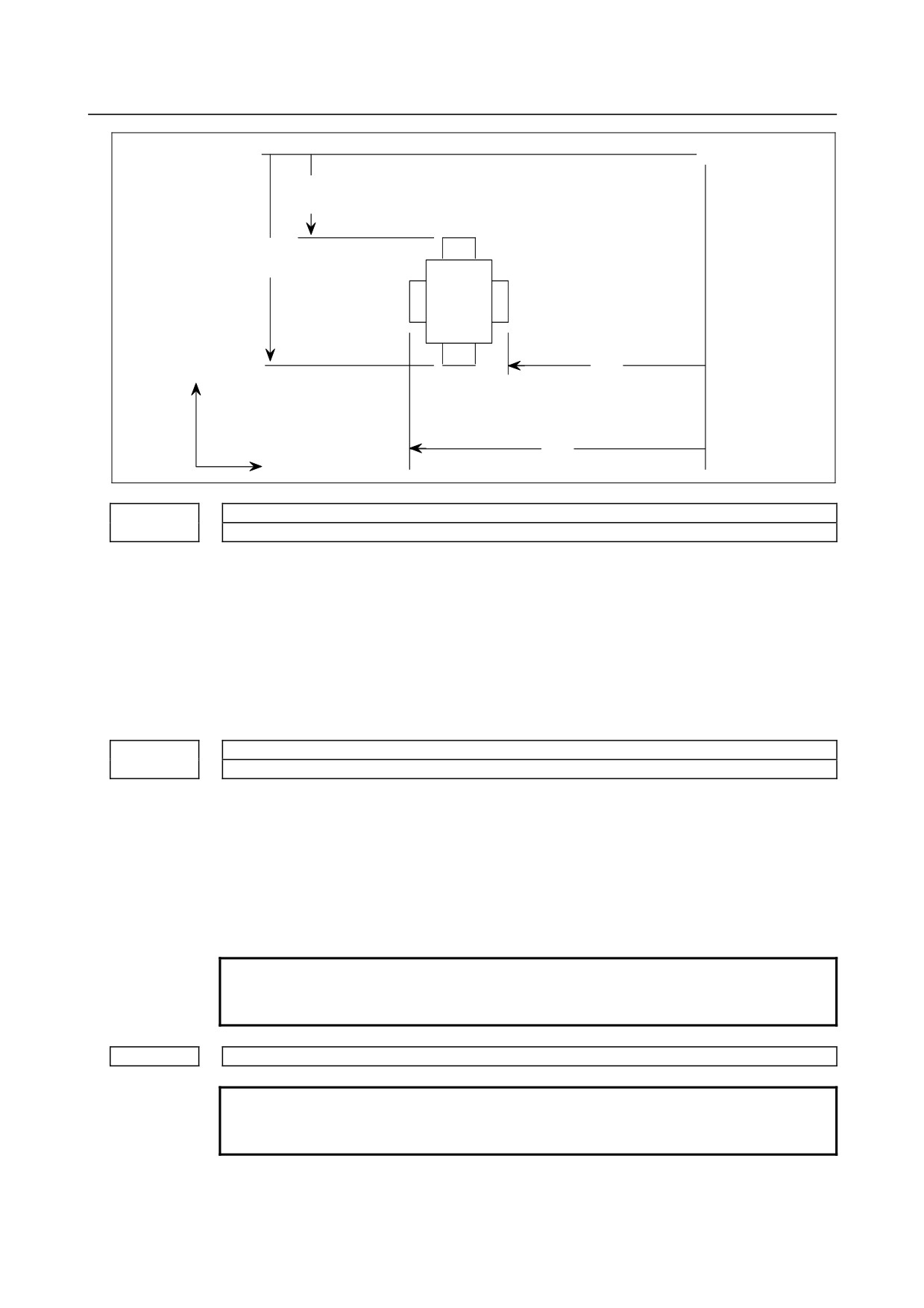
Distance to X-axis + contact surface of touch sensor 1 (X1P)
5015
Distance to X-axis - contact surface of touch sensor 1 (X1M)
5016
Distance to Z-axis + contact surface of touch sensor 1 (Z1P)
5017
Distance to Z-axis - contact surface of touch sensor 1 (Z1M)
5018
[Input type] Parameter input
[Data type] Real path
[Unit of data] mm, inch (machine unit)
[Min. unit of data] Depend on the increment system of the applied axis
[Valid data range] 9 digit of minimum unit of data (refer to standard parameter setting table (A))
(When the increment system is IS-B, -999999.999 to +999999.999.)
This parameter is related to the function for direct input of offset value measured B (T
series).
Set the distance (signed) from a measurement reference position to each contact surface
of a sensor. For a diameter specification axis, set a diameter value.
When arbitrary angular axis control is performed, set the distance in the Cartesian
coordinate system.
- 204 -
B-64310EN/02
4.DESCRIPTION OF PARAMETERS
○Measurement
reference
position
X1m
X-axis - contact surface
↓
X1p
←Z-axis + contact surface
Z-axis - contact surface
+X
Z1m
↑
X-axis + contact surface
Z1p
+Z
Tool offset number used with the function for direct input of offset value measured B
5020
[Input type] Parameter input
[Data type] Word path
[Valid data range] 0 to number of tool compensation values
Set a tool offset number used with the function for direct input of offset value measured B
(T series) (when a workpiece coordinate system shift amount is set). (Set the tool offset
number corresponding to a tool under measurement beforehand.) This parameter is valid
when automatic tool offset number selection is not performed (when bit 5 (QNI) of
parameter No. 5005 is set to 0).
Number of interpolation cycles of pulses stored until the tool is about to touch the touch sensor
5021
[Input type] Parameter input
[Data type] Byte path
[Valid data range] 0 to 8
When a touch sensor of one-point input is used with the function for direct input of offset
value measured B (T series), set the number of interpolation cycles of pulses stored until
the manually operated tool is about to touch the touch sensor. When 0 is set, the
specification of the maximum value 8 is assumed.
NOTE
This parameter is valid when bit 3 (TS1) of parameter No. 5004 is set
to 1.
5024
Number of tool compensation values
NOTE
When this parameter is set, the power must be turned off before
operation is continued.
[Input type] Parameter input
[Data type] Word path
- 205 -
4.DESCRIPTION OF PARAMETERS
B-64310EN/02
[Valid data range] 0 to number of tool compensation values
Set the maximum allowable number of tool compensation values used for each path.
Ensure that the total number of values set in parameter No. 5024 for the individual paths
is within the number of compensation values usable in the entire system.
If the total number of values set in parameter No. 5024 for the individual paths exceeds
the number of compensation values usable in the entire system, or 0 is set in parameter
No. 5024 for all paths, the number of compensation values usable for each path is a value
obtained by dividing the number of compensation values usable in the entire system by
the number of paths.
Tool compensation values as many as the number of compensation values used for each
path are displayed on the screen. If tool compensation numbers more than the number of
compensation values usable for each path are specified, an alarm is issued.
For example, 100 tool compensation sets are used, 120 sets may be allocated to path 1
and 80 sets to path 2. All of 200 sets need not be used.
Number of digits of an offset number used with a T code command
5028
[Input type] Parameter input
[Data type] Byte path
[Valid data range] 0 to 3
Specify the number of digits of a T code portion that is used for a tool offset number
(wear offset number when the tool geometry/wear compensation function is used).
When 0 is set, the number of digits is determined by the number of tool compensation
values.
When the number of tool compensation values is 1 to 9: Lower 1 digit
When the number of tool compensation values is 10 to 99: Lower 2 digits
When the number of tool compensation values is 100 to 200: Lower 3 digits
[Example] When an offset number is specified using the lower 2 digits of a T code, set 2 in
parameter No. 5028.
Txxxxxx yy
xxxxxx : Tool selection
yy : Tool offset number
NOTE
A value longer than the setting of parameter No. 3032 (allowable
number of digits of a T code) cannot be set.
5029
Number of tool compensation value memories common to paths
NOTE
When this parameter is set, the power must be turned off before
operation is continued.
[Input type] Parameter input
[Data type] Word
[Valid data range] 0 to number of tool compensation values
When using memories common to paths, set the number of common tool compensation
values in this parameter.
Ensure that the setting of this parameter does not exceed the number of tool compensation
values set for each path (parameter No. 5024).
[Example 1] When parameter No. 5029 = 10, parameter No. 5024 (path 1) = 15, and parameter No.
5024 (path 2) = 30 in a 2-path system, tool compensation numbers 1 to 10 of all paths are
made common.
- 206 -
B-64310EN/02
4.DESCRIPTION OF PARAMETERS
[Example 2] When parameter No. 5029 = 20 and the other conditions are the same as for Example 1,
tool compensation numbers 1 to 15 are made common.
NOTE
1 Ensure that the setting of parameter No. 5029 does not exceed the
number of tool compensation values for each path (parameter No.
5024). If the setting of parameter No. 5029 exceeds the number of
compensation values of a path, the least of the numbers of
compensation values in all paths is made common.
2 When 0 or a negative value is set, memories common to paths are
not used.
#7
#6
#5
#4
#3
#2
#1
#0
OWD
5040
[Input type] Parameter input
[Data type] Bit path
#0 OWD In radius programming (bit 1 (ORC) of parameter No. 5004 is set to 1),
0: Tool offset values of both geometry compensation and wear compensation are
specified by radius.
1: Tool offset value of geometry compensation is specified by radius and tool offset
value of wear compensation is specified by diameter, for an axis of diameter
programming.
NOTE
This parameter is valid when tool geometry/wear compensation is
enabled (bit 6 (NGW) of parameter No. 8136 is 0).
#7
#6
#5
#4
#3
#2
#1
#0
5042
OFC
OFA
[Input type] Parameter input
[Data type] Bit path
NOTE
When at least one of these parameters is set, the power must be
turned off before operation is continued.
#0 OFA
#1 OFC These bits are used to specify the increment system and valid data range of a tool offset
value.
For metric input
OFC
OFA
Unit
Valid data range
0
1
0.01mm
±9999.99mm
0
0
0.001mm
±9999.999mm
1
0
0.0001mm
±9999.9999mm
- 207 -
4.DESCRIPTION OF PARAMETERS
B-64310EN/02
For inch input
OFC
OFA
Unit
Valid data range
0
1
0.001inch
±999.999inch
0
0
0.0001inch
±999.9999inch
1
0
0.00001inch
±999.99999inch
Axis number for which Y-axis offset is used
5043
[Input type] Parameter input
[Data type] Byte path
[Valid data range] 0 to Number of controlled axes
Set the number of an axis for which the tool offset is corrected.
If 0 or a value beyond the valid data range is set, the Y-axis offset is applied to the Y-axis
of the basic three axes. If setting is made for the X- or Z-axis of the basic three axes, the
standard tool offset for the X- or Z-axis is not used, and only the Y-axis offset is used.
4.23 PARAMETERS OF CANNED CYCLES
4.23.1 Parameters of Canned Cycle for Drilling (1 of 2)
#7
#6
#5
#4
#3
#2
#1
#0
RTR
EXC
FXY
5101
M5B
EXC
FXY
[Input type] Parameter input
[Data type] Bit path
#0 FXY The drilling axis in the drilling canned cycle, or cutting axis in the grinding canned cycle
is:
0: In case of the Drilling canned cycle:
Z-axis at all times.
In case of the Grinding canned cycle:
• For the T series
Z-axis at all times.
• For the M series
G75,G77 command :Y-axis
G78,G79 command :Z-axis
1: Axis selected by the program
NOTE
1 In the case of the T series, this parameter is valid only for the
drilling canned cycle in the Series 10/11 format.
2 When this parameter is 1, the drilling axis determined by plane
selection (G17/G18/G19) in the drilling canned cycle in the T series
10/11 format. Therefore, the Y-axis is required to specify
G17/G19.
#1 EXC G81
0: Specifies a drilling canned cycle
1: Specifies an external operation command
- 208 -
B-64310EN/02
4.DESCRIPTION OF PARAMETERS
#2 RTR G83 and G87
0: Specify a high-speed peck drilling cycle
1: Specify a peck drilling cycle
#7 M5B In drilling canned cycles G76 and G87:
0: Outputs M05 before an oriented spindle stops
1: Not output M05 before an oriented spindle stops
#7
#6
#5
#4
#3
#2
#1
#0
RDI
RAB
F0C
QSR
5102
[Input type] Parameter input
[Data type] Bit path
#2 QSR Before a multiple repetitive canned cycle (G70 to G73) (T series) is started, a check to see
if the program contains a block that has the sequence number specified in address Q is:
0: Not made.
1: Made.
When 1 is set in this parameter and the sequence number specified in address Q is not
found, the alarm (PS0063) is issued and the canned cycle is not executed.
#3 F0C When the Series 10/11 format is used (with bit 1 (FCV) of parameter No.0001 set to 1), a
canned drilling cycle is specified using :
0: Series 10/11 format
1: Series 0 format. However, the number of repetitions is specified using address L.
#6 RAB When a canned drilling cycle using the Series 10/11 format is specified (with bit 1 (FCV)
of parameter No. 0001 set to 1 and bit 3 (F0C) of parameter No. 5102 set to 0), address R
specifies:
0: Increment command.
1: Absolute command with G code system A. With G code system B or C, G90 and
G91 are followed.
#7 RDI When a canned drilling cycle using the Series 10/11 format is specified (with bit 1 (FCV)
of parameter No. 0001 set to 1 and bit 3 (F0C) of parameter No. 5102 set to 0), address R
is based on:
0: Radius specification.
1: Diameter/radius specification of the drilling axis.
#7
#6
#5
#4
#3
#2
#1
#0
TCZ
PNA
DCY
5103
TCZ
DCY
SIJ
[Input type] Parameter input
[Data type] Bit path
#0 SIJ When the Series 10/11 program format is used (with bit 1 (FCV) of parameter No.0001
set to 1), a tool shift value for the drilling canned cycle G76 or G87 is specified by:
0: Address Q. Set a tool retraction direction in parameter No. 5148.
1: Address I, J, or K.
- 209 -
4.DESCRIPTION OF PARAMETERS
B-64310EN/02
#2 DCY When an axis (to be used as a drilling axis) perpendicular to the positioning plane is
specified in a drilling canned cycle:
0: The specified axis is used as a drilling axis.
1: The axis specified in the block where the G code for the drilling canned cycle is
specified is used as a drilling axis. The specified axis is used as a positioning axis.
NOTE
This parameter is valid when bit 0 (FXY) of parameter No. 5101 is
set to 1.
#3 PNA In a drilling canned cycle using the Series 10/11 format (with bit 1 (FCV) of parameter
No. 0001 set to 1 and bit 3 (F0C) of parameter No. 5102 set to 0), when a plane where no
axis is present is specified in the drilling canned cycle mode:
0: An alarm is issued.
1: No alarm is issued.
#6 TCZ In a tapping cycle (excluding rigid tapping), an accumulated zero check in the tapping
step (forward, backward) is:
0: Not performed.
1: Performed.
Execute a tapping cycle (excluding rigid tapping) with the servo feed forward (bit 1
(FEED) of parameter No. 2005). If an impact is detected, set this parameter to 1.
#7
#6
#5
#4
#3
#2
#1
#0
PCT
FCK
5104
PCT
[Input type] Parameter input
[Data type] Bit path
#2 FCK In a multiple repetitive canned cycle (G71/G72) (T series), the machining profile is:
0: Not checked.
1: Checked.
The target figure specified by G71 or G72 is checked for the following before machining
operation:
• If the start point of the canned cycle is less than the maximum value of the
machining profile even when the plus sign is specified for a finishing allowance, the
alarm (PS0322) is issued.
• If the start point of the canned cycle is greater than the minimum value of the
machining profile even when the minus sign is specified for a finishing allowance,
the alarm (PS0322) is issued.
• If an unmonotonous command of type I is specified for the axis in the cutting
direction, the alarm (PS0064 or PS0329) is issued.
• If an unmonotonous command is specified for the axis in the roughing direction, the
alarm (PS0064 or PS0329) is issued.
• If the program does not include a block that has a sequence number specified by
address Q, the alarm (PS0063) is issued. This check is made, regardless of bit 2
(QSR) of parameter No. 5102.
• If a command (G41/G42) on the blank side in tool nose radius compensation is
inadequate, the alarm (PS0328) is issued.
- 210 -
B-64310EN/02
4.DESCRIPTION OF PARAMETERS
#6 PCT A Q command in a tapping cycle is:
0: Disabled.
1: Enabled.
((High-speed) peck tapping cycle is assumed.)
When this parameter is set and the depth of cut for each time is specified with address Q
in a tapping cycle command, a peck tapping cycle is assumed.
In a peck tapping cycle, either a high-speed peck tapping cycle or a peck tapping cycle
can be selected by bit 5 (PCP) of parameter No. 5200.
Even when this parameter is set to 1, if Q is not specified or Q0 is specified, normal
tapping is performed.
NOTE
1 Set also parameter No. 5213.
2 In rigid tapping, the Q command is valid regardless of the setting of
this parameter.
3 For the M series, if this parameter is set to 1, the specification
equivalent to the FS0i-C is assumed.
#7
#6
#5
#4
#3
#2
#1
#0
K0D
M5T
RF2
RF1
SBC
5105
M5T
SBC
[Input type] Parameter input
[Data type] Bit path
#0 SBC In each of a drilling canned cycle, chamfering/corner rounding cycle, and optional-angle
chamfering/corner rounding (T series) cycle:
0: A single block stop is not carried out.
1: A single block stop is carried out.
#1 RF1 In a multiple repetitive canned cycle (G71/G72) (T series) of type I, roughing is:
0: Performed.
1: Not performed.
NOTE
When a roughing allowance (Δi/Δk) is specified using the Series
10/11 program format, roughing is performed, regardless of the
setting of this parameter.
#2 RF2 In a multiple repetitive canned cycle (G71/G72) (T series) of type II, roughing is:
0: Performed.
1: Not performed.
NOTE
When a roughing allowance (Δi/Δk) is specified using the Series
10/11 program format, roughing is performed, regardless of the
setting of this parameter.
#3 M5T When the rotation direction of the spindle is changed from forward rotation to reverse
rotation or from reserve rotation to forward rotation in a tapping cycle (G84/G88 with the
T series, or G84/G74 with the M series):
0: M05 is output before output of M04 or M03.
1: M05 is not output before output of M04 or M03.
- 211 -
4.DESCRIPTION OF PARAMETERS
B-64310EN/02
NOTE
1 This parameter is equivalent to bit 6 (M5T) of parameter No. 5101
of the FS0i-C.
2 For the T series, the logical level (0/1) is opposite to that of the
FS0i-C.
#4 K0D When K0 is specified in a drilling canned cycle (G80 to G89):
0: Drilling operation is not performed, but drilling data only is stored.
1: One drilling operation is performed.
#7
#6
#5
#4
#3
#2
#1
#0
GFX
5106
[Input type] Parameter input
[Data type] Bit path
NOTE
When this parameter is set, the power must be turned off before
operation is continued.
#0 GFX When grinding canned cycle option is specified, the G71, G72, G73, or G74 command is:
0: A multiple repetitive canned cycle (T series) command.
1: A grinding canned cycle command.
M code for C-axis clamping in a drilling canned cycle
5110
[Input type] Parameter input
[Data type] 2-word path
[Valid data range] 0 to 99999998
This parameter sets an M code for C-axis clamping in a drilling canned cycle.
Dwell time when C-axis unclamping is specified in drilling canned cycle
5111
[Input type] Parameter input
[Data type] 2-word path
[Valid data range] 0 to 32767
[Unit of data]
Increment system
IS-A
IS-B
IS-C
Unit
10
1
0.1
msec
(The increment system does not depend on whether inch input or metric input is used.)
This parameter sets the dwell time when C-axis unclamping is specified in a drilling
canned cycle.
Spindle forward-rotation M code in drilling canned cycle
5112
[Input type] Parameter input
[Data type] 2-word path
[Valid data range] 0 to 99999999
- 212 -
B-64310EN/02
4.DESCRIPTION OF PARAMETERS
This parameter sets the spindle forward-rotation M code in a drilling canned cycle.
NOTE
M03 is output when "0" is set.
Spindle reverse-rotation M code in drilling canned cycle
5113
[Input type] Parameter input
[Data type] 2-word path
[Valid data range] 0 to 99999999
This parameter sets the spindle reverse-rotation M code in a drilling canned cycle.
NOTE
M04 is output when "0" is set.
5114
Return value of high-speed peck drilling cycle
[Input type] Parameter input
[Data type] Real path
[Unit of data] mm, inch (input unit)
[Min. unit of data] Depend on the increment system of the reference axis
[Valid data range] 9 digit of minimum unit of data (refer to standard parameter setting table (A))
(When the increment system is IS-B, -999999.999 to +999999.999)
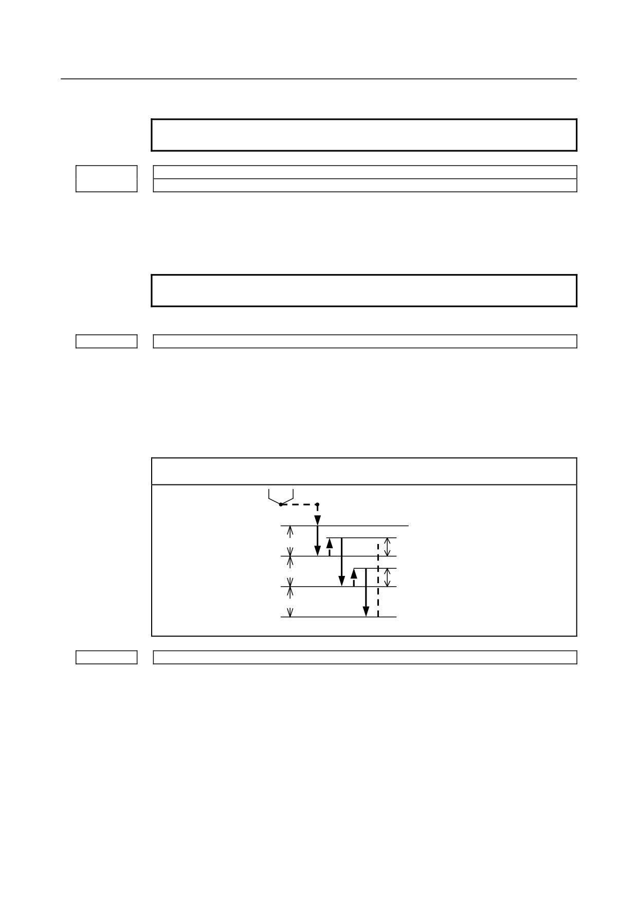
This parameter sets the return value in high-speed peck drilling cycle.
G73 (M series)
G83 (T series, when the parameter RTR (No.5101#2) is set to 0)
q : Depth of cut
d : Return value
R point
q
d
q
d
q
Z point
5115
Clearance value in a peck drilling cycle
[Input type] Parameter input
[Data type] Real path
[Unit of data] mm, inch (input unit)
[Min. unit of data] Depend on the increment system of the reference axis
[Valid data range] 9 digit of minimum unit of data (refer to standard parameter setting table (A))
(When the increment system is IS-B, -999999.999 to +999999.999)
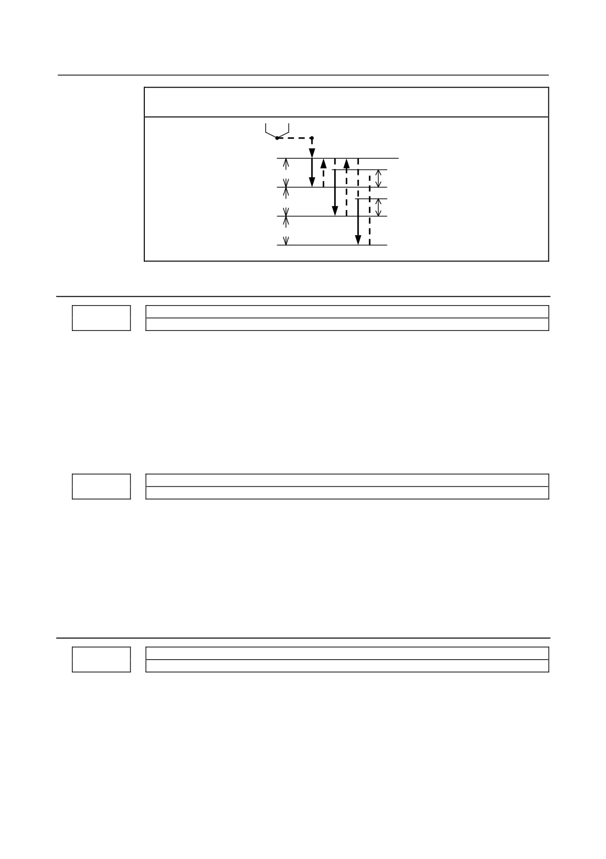
This parameter sets a clearance value in a peck drilling cycle.
- 213 -
4.DESCRIPTION OF PARAMETERS
B-64310EN/02
G83 (M series)
G83 (T series, when the parameter RTR (No.5101#2) is set to 1)
q : Depth of cut
d : Clearance value
R point
q
d
q
d
q
Z point
4.23.2 Parameters of Thread Cutting Cycle (T Series)
Cutting value (chamfering value) in thread cutting cycles G92 and G76
5130
[Input type] Parameter input
[Data type] Byte path
[Unit of data] 0.1
[Valid data range] 0 to 127
This parameter sets a cutting value (chamfering value) in the thread cutting cycle (G76)
of a multiple repetitive canned cycle (T series) and in the thread cutting cycle (G92) of a
canned cycle.
Let L b a lead. Then, a cutting value range from 0.1L to 12.7L is allowed.
To specify a cutting value of 10.0L, for example, specify 100 in this parameter.
Cutting angle in thread cutting cycles G92 and G76
5131
[Input type] Parameter input
[Data type] Byte path
[Unit of data] Degree
[Valid data range] 1 to 89
This parameter sets the cutting angle in the thread cutting cycle (G76) of a multiple
repetitive canned cycle (T series) and in the thread cutting cycle (G92) of a canned cycle.
When 0 is set, an angle of 45 degrees is specified.
4.23.3 Parameters of Multiple Repetitive Canned Cycle (T Series)
Depth of cut in multiple repetitive canned cycles G71 and G72
5132
[Input type] Parameter input
[Data type] Real path
[Unit of data] mm, inch (input unit)
[Min. unit of data] Depend on the increment system of the reference axis
[Valid data range] 0 or positive 9 digit of minimum unit of data (refer to the standard parameter setting table
(B))
(When the increment system is IS-B, 0.0 to +999999.999)
This parameter sets the depth of cut in multiple repetitive canned cycles G71 and G72 (T
series).
- 214 -
B-64310EN/02
4.DESCRIPTION OF PARAMETERS
This parameter is not used with the Series 10/11 program format.
NOTE
Specify a radius value at all times.
Escape in multiple repetitive canned cycles G71 and G72
5133
[Input type] Parameter input
[Data type] Real path
[Unit of data] mm, inch (input unit)
[Min. unit of data] Depend on the increment system of the reference axis
[Valid data range] 0 or positive 9 digit of minimum unit of data (refer to the standard parameter setting table
(B))
(When the increment system is IS-B, 0.0 to +999999.999)
This parameter sets the escape in multiple repetitive canned cycles G71 and G72 (T
series).
NOTE
Specify a radius value at all times.
Clearance value in multiple repetitive canned cycles G71 and G72
5134
[Input type] Parameter input
[Data type] Real path
[Unit of data] mm, inch (input unit)
[Min. unit of data] Depend on the increment system of the reference axis
[Valid data range] 0 or positive 9 digit of minimum unit of data (refer to the standard parameter setting table
(B))
(When the increment system is IS-B, 0.0 to +999999.999)
This parameter sets a clearance value up to the cutting feed start point in multiple
repetitive canned cycles (G71/G72) (T series).
NOTE
Specify a radius value at all times.
Retraction distance in the multiple repetitive canned cycle G73 (second axis on the plane)
5135
[Input type] Parameter input
[Data type] Real path
[Unit of data] mm, inch (input unit)
[Min. unit of data] Depend on the increment system of the reference axis
[Valid data range] 9 digit of minimum unit of data (refer to standard parameter setting table (A))
(When the increment system is IS-B, -999999.999 to +999999.999)
This parameter sets a retraction distance along the second axis on the plane in the
multiple repetitive canned cycle G73 (T series). This parameter is not used with the Series
10/11 program format.
NOTE
Specify a radius value at all times.
- 215 -
4.DESCRIPTION OF PARAMETERS
B-64310EN/02
Retraction distance in the multiple repetitive canned cycle G73 (first axis on the plane)
5136
[Input type] Parameter input
[Data type] Real path
[Unit of data] mm, inch (input unit)
[Min. unit of data] Depend on the increment system of the reference axis
[Valid data range] 9 digit of minimum unit of data (refer to standard parameter setting table (A))
(When the increment system is IS-B, -999999.999 to +999999.999)
This parameter sets a retraction distance along the first axis on the plane in the multiple
repetitive canned cycle G73 (T series). This parameter is not used with the Series 10/11
program format.
NOTE
Specify a radius value at all times.
Number of divisions in the multiple repetitive canned cycle G73
5137
[Input type] Parameter input
[Data type] 2-word path
[Unit of data] Cycle
[Valid data range] 1 to 99999999
This parameter sets the number of divisions in the multiple repetitive canned cycle G73
(T series).
This parameter is not used with the Series 10/11 program format.
Return in multiple repetitive canned cycles G74 and G75
5139
[Input type] Parameter input
[Data type] Real path
[Unit of data] mm, inch (input unit)
[Min. unit of data] Depend on the increment system of the reference axis
[Valid data range] 0 or positive 9 digit of minimum unit of data (refer to the standard parameter setting table
(B))
(When the increment system is IS-B, 0.0 to +999999.999)
This parameter sets the return in multiple repetitive canned cycles G74 and G75 (T
series).
NOTE
Specify a radius value at all times.
Minimum depth of cut in the multiple repetitive canned cycle G76
5140
[Input type] Parameter input
[Data type] Real path
[Unit of data] mm, inch (input unit)
[Min. unit of data] Depend on the increment system of the reference axis
[Valid data range] 0 or positive 9 digit of minimum unit of data (refer to the standard parameter setting table
(B))
(When the increment system is IS-B, 0.0 to +999999.999)
- 216 -
B-64310EN/02
4.DESCRIPTION OF PARAMETERS
This parameter sets a minimum depth of cut in the multiple repetitive canned cycle G76
(T series) so that the depth of cut does not become too small when the depth of cut is
constant.
NOTE
Specify a radius value at all times.
Finishing allowance in the multiple repetitive canned cycle G76
5141
[Input type] Parameter input
[Data type] Real path
[Unit of data] mm, inch (input unit)
[Min. unit of data] Depend on the increment system of the reference axis
[Valid data range] 0 or positive 9 digit of minimum unit of data (refer to the standard parameter setting table
(B))
(When the increment system is IS-B, 0.0 to +999999.999)
This parameter sets the finishing allowance in multiple repetitive canned cycle G76 (T
series).
NOTE
Specify a radius value at all times.
Repetition count of final finishing in multiple repetitive canned cycle G76
5142
[Input type] Parameter input
[Data type] 2-word path
[Unit of data] Cycle
[Valid data range] 1 to 99999999
This parameter sets the number of final finishing cycle repeats in the multiple repetitive
canned cycle G76 (T series).
When 0 is set, only one final finishing cycle is executed.
Tool nose angle in multiple repetitive canned cycle G76
5143
[Input type] Parameter input
[Data type] Byte path
[Unit of data] Degree
[Valid data range] 0, 29, 30, 55, 60, 80
This parameter sets the tool nose angle in multiple repetitive canned cycle G76 (T series).
This parameter is not used with the Series 10/11 program format.
Allowable value 1 in multiple repetitive canned cycles G71 and G72
5145
[Input type] Parameter input
[Data type] Real path
[Unit of data] mm, inch (input unit)
[Min. unit of data] Depend on the increment system of the reference axis
[Valid data range] 0 or positive 9 digit of minimum unit of data (refer to the standard parameter setting table
(B))
(When the increment system is IS-B, 0.0 to +999999.999)
- 217 -
4.DESCRIPTION OF PARAMETERS
B-64310EN/02
If a monotonous command of type I or II is not specified for the axis in the roughing
direction, the alarm
(PS0064 or PS0329) is issued. When a program is created
automatically, a very small unmonotonous figure may be produced. Set an unsigned
allowable value for such an unmonotonous figure. By doing so, G71 and G72 cycles can
be executed even in a program including an unmonotonous figure.
[Example] Suppose that a G71 command where the direction of the cutting axis (X-axis) is minus
and the direction of the roughing axis (Z-axis) is minus is specified. In such a case, when
an unmonotonous command for moving 0.001 mm in the plus direction along the Z-axis
is specified in a target figure program, roughing can be performed according to the
programmed figure without an alarm by setting 0.001 mm in this parameter.
NOTE
A check for a monotonous figure is made at all times during G71
and G72 cycles. A figure (programmed path) is checked. When tool
nose radius compensation is performed, a path after compensation
is checked. When bit 2 (FCK) of parameter No. 5104 is set to 1, a
check is made before G71or G72 cycle operation. In this case, not
a path after tool nose radius compensation but a programmed path
is checked.
Note that no alarm is issued when an allowable value is set.
Use a radius value to set this parameter at all times.
Allowable value 2 in multiple repetitive canned cycles G71 and G72
5146
[Input type] Parameter input
[Data type] Real path
[Unit of data] mm, inch (input unit)
[Min. unit of data] Depend on the increment system of the reference axis
[Valid data range] 0 to cut of depth
If a monotonous command of type I is not specified for the axis in the cutting direction,
the alarm (PS0064 or PS0329) is issued. When a program is created automatically, a very
small unmonotonous figure may be produced. Set an unsigned allowable value for such
an unmonotonous figure. By doing so, G71 and G72 cycles can be executed even in a
program including an unmonotonous figure.
The allowable value is clamped to the depth of cut specified by a multiple repetitive
canned cycle.
[Example] Suppose that a G71 command where the direction of the cutting axis (X-axis) is minus
and the direction of the roughing axis (Z-axis) is minus is specified. In such a case, when
an unmonotonous command for moving 0.001 mm in the minus direction along the
X-axis is specified in a target figure program for moving from the bottom of cutting to the
end point, roughing can be performed according to the programmed figure without an
alarm by setting 0.001 mm in this parameter.
- 218 -
B-64310EN/02
4.DESCRIPTION OF PARAMETERS
NOTE
A check for a monotonous figure is made at all times during G71
and G72 cycles. A figure (programmed path) is checked. When tool
nose radius compensation is performed, a path after compensation
is checked. When bit 2 (FCK) of parameter No. 5104 is set to 1, a
check is made before G71 or G72 cycle operation. In this case, not
a path after tool nose radius compensation but a programmed path
is checked.
Note that no alarm is issued when an allowable value is set.
Use a radius value to set this parameter at all times.
4.23.4 Parameters of Canned Cycle for Drilling (2 of 2)
5148
Tool retraction direction after orientation in a fine boring cycle or back boring cycle
[Input type] Parameter input
[Data type] Byte axis
[Valid data range] -5 to 5
This parameter sets an axis and direction for tool retraction after spindle orientation in a
fine boring cycle or back boring cycle. For each boring axis, an axis and direction for tool
retraction after orientation can be set. Set a signed axis number.
[Example] Suppose that:
When the boring axis is the X-axis, the tool retraction direction after orientation is -Y.
When the boring axis is the Y-axis, the tool retraction direction after orientation is +Z.
When the boring axis is the Z-axis, the tool retraction direction after orientation is -X.
Then, set the following (assuming that the first, second, and third axes are the X-axis,
Y-axis, and Z-axis, respectively):
Set -2 in the parameter for the first axis. (The tool retraction direction is -Y.)
Set 3 in the parameter for the second axis. (The tool retraction direction is -Y.)
Set -1 in the parameter for the third axis. (The tool retraction direction is -X.)
Set 0 for other axes.
5149
Override for retraction in a boring cycle (G85/G89)
[Input type] Parameter input
[Data type] Word path
[Unit of data] %
[Valid data range] 0 to 2000
This parameter sets an override value for the feedrate of retraction in a boring cycle. The
cutting feedrate override signal is valid, regardless of the setting of this parameter. The
setting of this parameter is valid even when the override cancel signal is set to 1.
When 0 is set in this parameter, the following operation is performed:
For the T series
Operation performed when 200 is set in this parameter (The retraction feedrate is two
times greater than the cutting feedrate.)
For the M series
Operation performed when 100 is set in this parameter (The retraction feedrate is the
cutting feedrate.)
- 219 -
4.DESCRIPTION OF PARAMETERS
B-64310EN/02
#7
#6
#5
#4
#3
#2
#1
#0
CYM
5160
TSG
CYM
NOL
OLS
[Input type] Parameter input
[Data type] Bit path
#1 OLS When an overload torque detection signal is received in a peck drilling cycle of a small
diameter, the feedrate and spindle speed are:
0: Not changed.
1: Changed.
#2 NOL When the depth of cut per action is satisfied although no overload torque detection signal
is received in a peck drilling cycle of a small diameter, the feedrate and spindle speed are:
0: Not changed.
1: Changed.
#3 CYM When a subprogram call is specified in a block specifying other commands in the canned
cycle mode:
0: No alarm is issued. (When a command of address P is specified, the command is
handled as both a command specifying a dwell time and a command specifying a
subprogram number in a canned cycle.)
1: An alarm is issued.
#4 TSG A dependence of the overload torque detection signal in a peck drilling cycle (M series)
on the parameter setting of the skip function:
0: Exists.
1: Does not exist.
NOTE
When this parameter is 1, even if the setting of the skip signal is
disabled, the X address can be used as the overload torque
detection signal. At this time, parameter No. 3012 and bit 1 (SK0)
of parameter No. 6200 is valid.
5163
M code that specifies the peck drilling cycle mode of a small diameter
[Input type] Parameter input
[Data type] 2-word path
[Valid data range] 1 to 99999999
This parameter sets an M code that specifies the peck drilling cycle mode of a small
diameter.
5164
Percentage of the spindle speed to be changed at the start of the next advancing after an overload
torque detection signal is received
[Input type] Parameter input
[Data type] Word path
[Unit of data] %
[Valid data range] 1 to 255
- 220 -
B-64310EN/02
4.DESCRIPTION OF PARAMETERS
This parameter sets the percentage of the spindle speed to be changed at the start of the
next advancing after the tool is retracted because the overload torque detection signal is
received.
S2 = S1 × d1 ÷ 100
S1: Spindle speed to be changed
S2: Spindle speed changed
Set d1 as a percentage.
NOTE
When 0 is set, the spindle speed is not changed.
5165
Percentage of the spindle speed to be changed at the start of the next advancing when no overload
torque detection signal is received
[Input type] Parameter input
[Data type] Word path
[Unit of data] %
[Valid data range] 1 to 255
This parameter sets the percentage of the spindle speed to be changed at the start of the
next advancing after the tool is retracted without the overload torque detection signal
received.
S2 = S1 × d2 ÷ 100
S1: Spindle speed to be changed
S2: Spindle speed changed
Set d2 as a percentage.
NOTE
When 0 is set, the spindle speed is not changed.
5166
Percentage of the cutting feedrate to be changed at the start of the next cutting after an overload torque
detection signal is received
[Input type] Parameter input
[Data type] Word path
[Unit of data] %
[Valid data range] 1 to 255
This parameter sets the percentage of the cutting feedrate to be changed at the start of
cutting after the tool is retracted and advances because the overload torque detection
signal is received.
F2 = F1 × b1 ÷ 100
F1: Cutting feedrate to be changed
F2: Cutting feedrate changed
Set b1 as a percentage.
NOTE
When 0 is set, the cutting feedrate is not changed.
5167
Percentage of the cutting feedrate to be changed at the start of the next cutting when no overload
torque detection signal is received
[Input type] Parameter input
- 221 -
4.DESCRIPTION OF PARAMETERS
B-64310EN/02
[Data type] Word path
[Unit of data] %
[Valid data range] 1 to 255
This parameter sets the percentage of the cutting feedrate to be changed at the start of
cutting after the tool is retracted and advances without the overload torque detection
signal received.
F2 = F1 × b2 ÷ 100
F1: Cutting feedrate to be changed
F2: Cutting feedrate changed
Set b2 as a percentage.
NOTE
When 0 is set, the cutting feedrate is not changed.
5168
Lower limit of the percentage of the cutting feedrate in a peck drilling cycle of a small diameter
[Input type] Parameter input
[Data type] Byte path
[Unit of data] %
[Valid data range] 1 to 255
This parameter sets the lower limit of the percentage of the cutting feedrate changed
repeatedly to the specified cutting feedrate.
FL = F × b3 ÷ 100
F: Specified cutting feedrate
FL: Changed cutting feedrate
Set b3 as a percentage.
5170
Number of the macro variable to which to output the total number of retractions during cutting
[Input type] Parameter input
[Data type] Word path
[Valid data range] 100 to 149
This parameter sets the number of the custom macro common variable to which to output
the total number of times the tool is retracted during cutting. The total number cannot be
output to common variables #500 to #599.
5171
Number of the macro variable to which to output the total number of retractions because of the
reception of an overload torque detection signal
[Input type] Parameter input
[Data type] Word path
[Valid data range] 100 to 149
This parameter sets the number of the custom macro common variable to which to output
the total number of times the tool is retracted after the overload torque detection signal is
received during cutting. The total number cannot be output to common variables #500 to
#599.
5172
Feedrate of retraction to point R when no address I is specified
[Input type] Parameter input
[Data type] Real path
- 222 -
B-64310EN/02
4.DESCRIPTION OF PARAMETERS
[Unit of data] mm/min, inch/min (input unit)
[Min. unit of data] Depend on the increment system of the reference axis
[Valid data range] Refer to the standard parameter setting table (C)
(When the increment system is IS-B, 0.0 to +999000.0)
This parameter sets the feedrate of retraction to point R when no address I is specified.
5173
Feedrate of advancing to the position just before the bottom of a hole when no address I is specified
[Input type] Parameter input
[Data type] Real path
[Unit of data] mm/min, inch/min (input unit)
[Min. unit of data] Depend on the increment system of the reference axis
[Valid data range] Refer to the standard parameter setting table (C)
(When the increment system is IS-B, 0.0 to +999000.0)
This parameter sets the feedrate of advancing to the position just before the bottom of a
previously machined hole when no address I is specified.
5174
Clearance in a peck drilling cycle of a small diameter
[Input type] Parameter input
[Data type] Real path
[Unit of data] mm, inch (input unit)
[Min. unit of data] Depend on the increment system of the reference axis
[Valid data range] 9 digit of minimum unit of data (refer to standard parameter setting table (A))
(When the increment system is IS-B, -999999.999 to +999999.999)
This parameter sets the clearance in a peck drilling cycle of a small diameter.
4.23.5 Parameters of Canned Cycle for Grinding (for Grinding
Machine)
Grinding axis number in Traverse Grinding Cycle(G71)
5176
Grinding axis number in Plunge Grinding Cycle(G75)
[Input type] Parameter input
[Data type] Byte path
[Valid data range] 0 to Number of controlled axes
For the Lathe system:
Set the Grinding axis number of Traverse Grinding Cycle(G71).
For the Machining Center system:
Set the Grinding axis number of Plunge Grinding Cycle(G75).
NOTE
The axis number except for the cutting axis can be specified. When
the axis number which is same to cutting axis is specified, PS0456
alarm is issued at the time of execution. The Grinding Cycle is
executed when this parameter value is 0, PS0456 alarm is also
issued.
- 223 -
4.DESCRIPTION OF PARAMETERS
B-64310EN/02
Grinding axis number of Traverse direct constant-size Grinding cycle(G72)
5177
Grinding axis number of Direct Constant Dimension Plunge Grinding Cycle(G77)
[Input type] Parameter input
[Data type] Byte path
[Valid data range] 0 to Number of controlled axes
For the Lathe system:
Set the Grinding axis number of Traverse direct constant-size Grinding cycle(G72).
For the Machining Center system:
Set the Grinding axis number of Direct Constant Dimension Plunge Grinding Cycle
(G77).
NOTE
The axis number except for the cutting axis can be specified. When
the axis number which is same to cutting axis is specified, PS0456
alarm is issued at the time of execution. The Grinding Cycle is
executed when this parameter value is 0, PS0456 alarm is also
issued.
Grinding axis number of Oscillation Grinding Cycle(G73)
5178
Grinding axis number of Continuous feed surface grinding cycle(G78)
[Input type] Parameter input
[Data type] Byte path
[Valid data range] 0 to Number of controlled axes
For the Lathe system:
Set the Grinding axis number of Oscillation Grinding Cycle(G73).
For the Machining Center system:
Set the Grinding axis number of Continuous feed surface grinding cycle(G78).
NOTE
The axis number except for the cutting axis can be specified. When
the axis number which is same to cutting axis is specified, PS0456
alarm is issued at the time of execution. The Grinding Cycle is
executed when this parameter value is 0, PS0456 alarm is also
issued.
Grinding axis number of Oscillation Direct Fixed Dimension Grinding Cycle(G74)
5179
Grinding axis number of Intermittent feed surface grinding cycle(G79)
[Input type] Parameter input
[Data type] Byte path
[Valid data range] 0 to Number of controlled axes
For the Lathe system:
Set the Grinding axis number of Oscillation Direct Fixed Dimension Grinding
Cycle(G74).
For the Machining Center system:
Set the Grinding axis number of Intermittent feed surface grinding cycle(G79).
- 224 -
B-64310EN/02
4.DESCRIPTION OF PARAMETERS
NOTE
The axis number except for the cutting axis can be specified. When
the axis number which is same to cutting axis is specified, PS0456
alarm is issued at the time of execution. The Grinding Cycle is
executed when this parameter value is 0, PS0456 alarm is also
issued.
5180
Axis number of dressing axis in Plunge grinding cycle(G75)
[Input type] Parameter input
[Data type] Byte path
[Valid data range] 0 to Number of controlled axes
Set the axis number of dressing axis in Plunge grinding cycle(G75).
NOTE
The axis number except for the cutting axis or grinding axis can be
specified. When the axis number which is same to cutting axis or
grinding axis is specified, PS0456 alarm is issued at the time of
execution. The Grinding Cycle is executed when this parameter
value is 0 and address "L" is specified in NC program, the PS0456
alarm is also issued.
5181
Axis number of dressing axis in Direct constant dimension plunge grinding cycle(G75)
[Input type] Parameter input
[Data type] Byte path
[Valid data range] 0 to Number of controlled axes
Set the axis number of dressing axis in Direct constant dimension plunge grinding
cycle(G75).
NOTE
The axis number except for the cutting axis or grinding axis can be
specified. When the axis number which is same to cutting axis or
grinding axis is specified, PS0456 alarm is issued at the time of
execution. The Grinding Cycle is executed when this parameter
value is 0 and address "L" is specified in NC program, the PS0456
alarm is also issued.
5182
Axis number of dressing axis in Continuous feed surface grinding cycle(G78)
[Input type] Parameter input
[Data type] Byte path
[Valid data range] 0 to Number of controlled axes
Set the axis number of dressing axis in Continuous feed surface grinding cycle(G78).
- 225 -
4.DESCRIPTION OF PARAMETERS
B-64310EN/02
NOTE
The axis number except for the cutting axis or grinding axis can be
specified. When the axis number which is same to cutting axis or
grinding axis is specified, PS0456 alarm is issued at the time of
execution. The Grinding Cycle is executed when this parameter
value is 0 and address "L" is specified in NC program, the PS0456
alarm is also issued.
5183
Axis number of dressing axis in Intermittent feed surface grinding cycle(G79)
[Input type] Parameter input
[Data type] Byte path
[Valid data range] 0 to Number of controlled axes
Set the axis number of dressing axis in Intermittent feed surface grinding cycle(G79).
NOTE
The axis number except for the cutting axis or grinding axis can be
specified. When the axis number which is same to cutting axis or
grinding axis is specified, PS0456 alarm is issued at the time of
execution. The Grinding Cycle is executed when this parameter
value is 0 and address "L" is specified in NC program, the PS0456
alarm is also issued.
4.24 PARAMETERS OF RIGID TAPPING (1 OF 2)
#7
#6
#5
#4
#3
#2
#1
#0
SRS
FHD
PCP
DOV
SIG
CRG
G84
5200
FHD
PCP
DOV
SIG
CRG
G84
[Input type] Parameter input
[Data type] Bit path
#0 G84 Method for specifying rigid tapping:
0: An M code specifying the rigid tapping mode is specified prior to the issue of the
G84 (or G74) command. (See parameter No.5210).
1: An M code specifying the rigid tapping mode is not used. (G84 cannot be used as a
G code for the tapping cycle; G74 cannot be used for the reverse tapping cycle.)
#2 CRG Rigid mode when a rigid mode cancel command is specified (G80, G01 group G code,
reset, etc.) :
0: Canceled after rigid tapping signal RGTAP is set to "0".
1: Canceled before rigid tapping signal RGTAP is set to "0".
#3 SIG When gears are changed for rigid tapping, the use of SINDs is:
0: Not permitted.
1: Permitted.
#4 DOV Override during extraction in rigid tapping:
0: Invalidated
1: Validated (The override value is set in parameter No.5211. However, set an override
value for rigid tapping return in parameter No.5381.)
- 226 -
B-64310EN/02
4.DESCRIPTION OF PARAMETERS
#5 PCP Address Q is specified in a tapping cycle/rigid tapping:
0: A high-speed peck tapping cycle is assumed.
1: A peck tapping cycle is assumed.
NOTE
In a tapping cycle, this parameter is valid when bit 6 (PCT) of
parameter No. 5104 is 1. When bit 6 (PCT) of parameter No.
5104 is 0, a (high-speed) peck tapping cycle is not assumed.
#6 FHD Feed hold and single block in rigid tapping:
0: Invalidated
1: Validated
#7 SRS To select a spindle used for rigid tapping in multi-spindle control:
0: The spindle selection signals SWS1 and SWS2 are used. (These signals are used
also for multi-spindle control.)
1: The rigid tapping spindle selection signals RGTSP1 and RGTSP2 are used. (These
signals are provided expressly for rigid tapping.)
#7
#6
#5
#4
#3
#2
#1
#0
5201
OV3
OVU
TDR
[Input type] Parameter input
[Data type] Bit path
#2 TDR Cutting time constant in rigid tapping:
0: Uses a same parameter during cutting and extraction (Parameter Nos. 5261 through
5264)
1: Not use a same parameter during cutting and extraction
Parameter Nos. 5261 to 5264: Time constant during cutting
Parameter Nos. 5271 to 5274: Time constant during extraction
#3 OVU The increment unit of the override parameter (No.5211) for tool rigid tapping extraction
is:
0:
1%
1:
10%
#4 OV3 A spindle speed for extraction is programmed, so override for extraction operation is:
0: Disabled.
1: Enabled.
#7
#6
#5
#4
#3
#2
#1
#0
5202
OVE
IRR
RG3
ORI
[Input type] Parameter input
[Data type] Bit path
NOTE
When at least one of these parameters is set, the power must be
turned off before operation is continued.
- 227 -
4.DESCRIPTION OF PARAMETERS
B-64310EN/02
#0 ORI When rigid tapping is started:
0: Spindle orientation is not performed.
1: Spindle orientation is performed.
This parameter can be used only for a serial spindle.
This spindle orientation performs reference position return in the serial spindle/servo
mode. The stop position can be changed using the serial spindle parameter No.4073.
#1 RG3 A rigid tapping return operation is specified:
0:
With input signal RTNT <G062.6>.
1:
With one-shot G code G30.
NOTE
To use this function, set bit 0 (G84) of parameter No. 5200 to 0.
#4 IRR As the in-position width at point R after movement from point I to point R in rigid
tapping:
0: The in-position widths dedicated to rigid tapping (parameters Nos. 5300 and 5302)
are selected.
1: The normal in-position width (parameter No.1826) is selected.
#6 OVE The specification range of extraction override command (address J) by rigid tapping
program specification is:
0:
100% to 200%.
1:
100% to 2000%.
NOTE
1 To enable the extraction override command (address J) by
program specification, set bit 4 (OV3) of parameter No.5201 to 1.
2 When this parameter is set to 1, the operation equivalent to that of
the FS0i-C is assumed.
#7
#6
#5
#4
#3
#2
#1
#0
OVS
RFF
5203
RBL
OVS
RFF
[Input type] Parameter input
[Data type] Bit path
#2 RFF In rigid tapping, feed forward is:
0: Disabled.
1: Enabled. (Recommended)
As the standard setting, set 1.
At the same time, set the parameter for the advanced preview feed forward coefficient for
the tapping axis and the parameter for the advance preview feed forward coefficient for
the spindle so that these values match.
• Advanced preview feed forward coefficient for the tapping axis: Parameter No.2092
(or parameter No.2144 if the cutting/rapid traverse feed forward function is enabled
(bit 4 of parameter No.2214 is set to 1))
• Advanced preview feed forward coefficient for the spindle: Parameter No.4344
NOTE
This parameter is valid when a serial spindle is used.
- 228 -
B-64310EN/02
4.DESCRIPTION OF PARAMETERS
#4 OVS In rigid tapping, override by the feedrate override select signal and cancellation of
override by the override cancel signal is:
0: Disabled.
1: Enabled.
When feedrate override is enabled, extraction override is disabled.
The spindle override is clamped to 100% during rigid tapping, regardless of the setting of
this parameter.
#5 RBL As acceleration/deceleration for rigid tapping cutting feed:
0: Linear acceleration/deceleration is used.
1: Bell-shaped acceleration/deceleration is used.
NOTE
The rigid tapping bell-shaped acceleration/deceleration option is
required.
#7
#6
#5
#4
#3
#2
#1
#0
RIP
RTX
5209
RIP
[Input type] Parameter input
[Data type] Bit path
#0 RTX In rigid tapping in a T series, the tapping axis is:
0: Selected by selecting a plane.
1: Always assumed to be the Z-axis for G84 or the X-axis for G88.
NOTE
This parameter becomes invalid when bit 1 (FCV) of parameter
No.0001 is set to 1, and rigid tapping is specified using the
Series10/11 format.
#1 RIP When a movement from the initial point to point R is made, the in-position check is:
0: Dependent on the setting of bit 5 (NCI) of parameter No. 1601.
1: Performed.
NOTE
This parameter is valid when bit 5 (NCI) of parameter No.1601 is
set to 1 and bit 4 (IRR) of parameter No.5202 is set to 0.
If bit 5 (NCI) of parameter No.1601 is set to 0, the in-position check
is performed regardless of the setting of this parameter.
5210
Rigid tapping mode specification M code
[Input type] Parameter input
[Data type] 2-word path
[Valid data range] 0 to 65535
This parameter sets an M code that specifies the rigid tapping mode.
The M code is judged to be 29 (M29) when 0 is set.
- 229 -
4.DESCRIPTION OF PARAMETERS
B-64310EN/02
5211
Override value during rigid tapping extraction
[Input type] Parameter input
[Data type] Word path
[Unit of data] 1% or 10%
[Valid data range] 0 to 200
The parameter sets the override value during rigid tapping extraction.
NOTE
The override value is valid when bit 4 (DOV) of parameter No.5200 is
set to 1. When bit 3 (OVU) of parameter No.5201 is set to 1, the unit
of set data is 10%. An override of up to 200% can be applied to
extraction.
5213
Return or clearance in peck tapping cycle
[Input type] Setting input
[Data type] Real path
[Unit of data] mm, inch (input unit)
[Min. unit of data] Depend on the increment system of the drilling axis
[Valid data range] 0 or positive 9 digit of minimum unit of data (refer to the standard parameter setting table
(B))
(When the increment system is IS-B, 0.0 to +999999.999)
This parameter sets the escape value of a high-speed peck tapping cycle or the clearance
value of a peck tapping cycle.
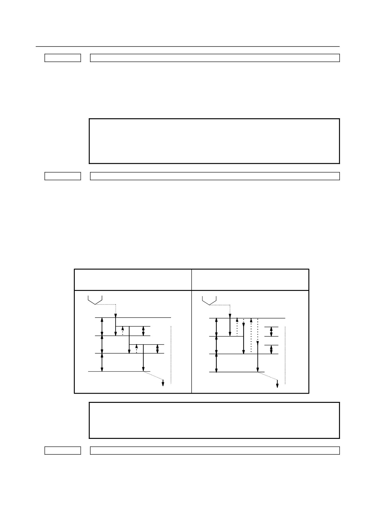
When the parameter PCP (bit 5 of No.5200) is
When the parameter PCP (bit 5 of No.5200)
set to 0.
is set to 1.
q : Depth of cut
q : Depth of cut
d : Return value
d : Clearance value
R point
R point
q
q
d
d
q
q
d
d
q
q
Z point
Z point
NOTE
1 In a tapping cycle, this parameter is valid when bit 6 (PCT) of
parameter No. 5104 is 1.
2 For the diameter axis, set this parameter using the diameter value.
5214
Setting of an allowable rigid tapping synchronization error range
[Input type] Parameter input
[Data type] 2-word spindle
[Unit of data] Detection unit
[Valid data range] 0 to 99999999
- 230 -
B-64310EN/02
4.DESCRIPTION OF PARAMETERS
This parameter sets an allowable synchronization error range in rigid tapping.
If a synchronous error range exceeding the setting of this parameter is detected, the alarm
(SP0741) is issued. When 0 is set in this parameter, no synchronization error check is
made.
5221
Number of gear teeth on the spindle side in rigid tapping (first gear)
5222
Number of gear teeth on the spindle side in rigid tapping (second gear)
5223
Number of gear teeth on the spindle side in rigid tapping (third gear)
Number of gear teeth on the spindle side in rigid tapping (fourth gear)
5224
[Input type] Parameter input
[Data type] Word spindle
[Valid data range] 1 to 32767
Each of these parameters is used to set the number of gear teeth on the spindle side for
each gear in rigid tapping.
NOTE
When a position coder is attached to the spindle, set the same value
for all of parameters No.5221 through No.5224.
5231
Number of gear teeth on the position coder side in rigid tapping (first gear)
5232
Number of gear teeth on the position coder side in rigid tapping (second gear)
5233
Number of gear teeth on the position coder side in rigid tapping (third gear)
Number of gear teeth on the position coder side in rigid tapping (fourth gear)
5234
[Input type] Parameter input
[Data type] Word spindle
[Valid data range] 1 to 32767
Each of these parameters is used to set the number of gear teeth on the position coder side
for each gear in rigid tapping.
NOTE
When a position coder is attached to the spindle, set the same value
for all of parameters No.5231 through No.5234.
5241
Maximum spindle speed in rigid tapping (first gear)
5242
Maximum spindle speed in rigid tapping (second gear)
5243
Maximum spindle speed in rigid tapping (third gear)
Maximum spindle speed in rigid tapping (fourth gear)
5244
[Input type] Parameter input
[Data type] 2-word spindle
- 231 -
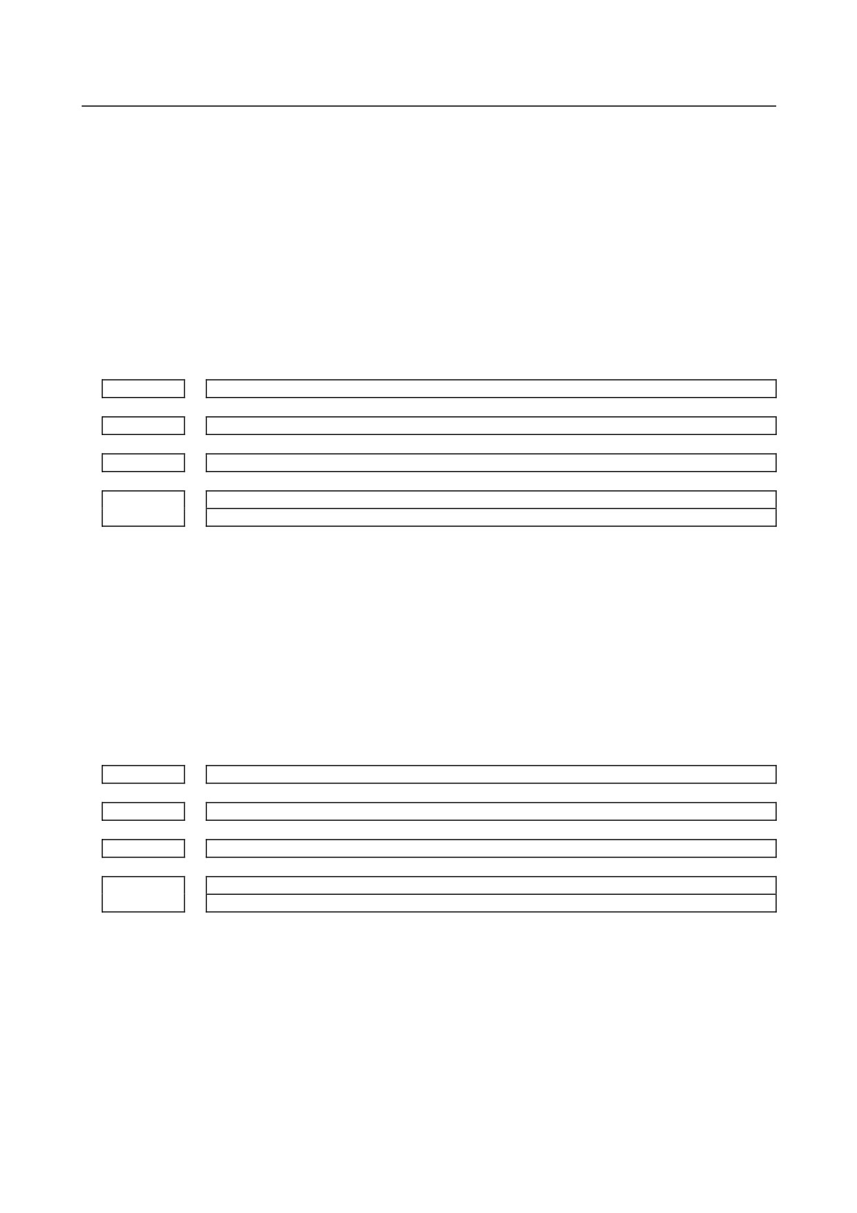
4.DESCRIPTION OF PARAMETERS
B-64310EN/02
[Unit of data] min-1
[Valid data range] 0 to 9999
Spindle position coder gear ratio
1 : 1
0 to 7400
1 : 2
0 to 9999
1 : 4
0 to 9999
1 : 8
0 to 9999
Each of these parameters is used to set a maximum spindle speed for each gear in rigid
tapping.
Set the same value for both parameter No.5241 and parameter No.5243 for a one-stage
gear system. For a two-stage gear system, set the same value as set in parameter No. 5242
in parameter No. 5243. Otherwise, alarm PS0200 will be issued. This applies to the M
series.
5261
Time constant for acceleration/deceleration in rigid tapping for each gear (first gear)
5262
Time constant for acceleration/deceleration in rigid tapping for each gear (second gear)
5263
Time constant for acceleration/deceleration in rigid tapping for each gear (third gear)
Time constant for acceleration/deceleration in rigid tapping for each gear (fourth gear)
5264
[Input type] Parameter input
[Data type] Word spindle
[Unit of data] msec
[Valid data range] 0 to 4000
Each of these parameters is used to set a linear acceleration/ deceleration time constant
for the spindle of each gear and the tapping axis in rigid tapping.
Set the period required to reach each maximum spindle speed (parameters No.5241 to
No.5244).
The set time constant, multiplied by the ratio of a specified S value to a maximum spindle
speed, is actually used as a time constant.
For bell-shaped acceleration/deceleration, set a time constant for a linear portion.
5271
Time constant for acceleration/deceleration in rigid tapping extraction (first gear)
5272
Time constant for acceleration/deceleration in rigid tapping extraction (second gear)
5273
Time constant for acceleration/deceleration in rigid tapping extraction (third gear)
Time constant for acceleration/deceleration in rigid tapping extraction (fourth gear)
5274
[Input type] Parameter input
[Data type] Word spindle
[Unit of data] msec
[Valid data range] 0 to 4000
Each of these parameters is used to set a linear acceleration/ deceleration time constant
for the spindle of each gear and tapping axis in extraction operation during rigid tapping.
For bell-shaped acceleration/deceleration, set a time constant for a linear portion.
- 232 -