FANUC Series 0i-MODEL D, Series 0i Mate-MODEL D. PARAMETER MANUAL - page 13
B-64310EN/02
4.DESCRIPTION OF PARAMETERS
#4 ZAG The deceleration function based on cutting load in AI contour control II (deceleration
based on Z-axis fall angle) is:
0: Not performed.
1: Performed.
When this parameter is set to 1, be sure to set parameter Nos. 8456, 8457, and 8458.
#7 NOF In AI contour control II, an F command is:
0: Not ignored.
1: Ignored.
When this parameter is set to 1, the specification of the maximum allowable feedrate set
in parameter No. 8465 is assumed.
8456
Override for range 2 that is applied during deceleration according to the cutting load in AI contour
control II
8457
Override for range 3 that is applied during deceleration according to the cutting load in AI contour
control II
8458
Override for range 4 that is applied during deceleration according to the cutting load in AI contour
control II
[Input type] Setting input
[Data type] Word path
[Unit of data] %
[Valid data range] 1 to 100
For the function of decelerating according to the cutting load in AI contour control II, the
override set in a parameter can be applied according to the angle at which the tool moves
downward along the Z-axis. The feedrate obtained according to other conditions is
multiplied by the override for the range containing angle ș at which the tool moves
downward.
However, when bit 1 (ZG2) of parameter No.19515 is set to 0, no parameter is available
to range 1, and 100% is applied at all times. When bit 1 (ZG2) of parameter No.19515 is
set to 1, set an override value for range 1 in parameter No.19516.
Range 1
0°≤ș<30°
Range 2
30°≤ș<45°
Range 3
45°≤ș<60°
Range 4
60°≤ș≤90°
#7
#6
#5
#4
#3
#2
#1
#0
8459
OVR
[Input type] Parameter input
[Data type] Bit path
#3 OVR In deceleration by speed difference or acceleration rate in advance preview control/AI
advance preview control/AI contour control/AI contour control II , an override is:
0: Disabled.
1: Enabled.
- 353 -
4.DESCRIPTION OF PARAMETERS
B-64310EN/02
An override is generally enabled for a specified speed and advance preview control/AI
advance preview control/AI contour control/AI contour control II is applied to the
specified speed. When this parameter is set to 1, an override is applied to the speed
managed by advance preview control/AI advance preview control/AI contour control/AI
contour control II.
Upper limit of the speed of advance preview control/AI advance preview control/AI contour control/AI
8465
contour control II
[Input type] Setting input
[Data type] Real path
[Unit of data] mm/min, inch/min, degree/min (input unit)
[Min. unit of data] Depend on the increment system of the reference axis
[Valid data range] Refer to the standard parameter setting table (C)
(When the increment system is IS-B, 0.0 to +999000.0)
This parameter sets the upper limit of the speed of advance preview control/AI advance
preview control/AI contour control/AI contour control II.
If a speed higher than this parameter is specified in the advance preview control/AI
advance preview control/AI contour control/AI contour control II mode, clamping is
performed at the speed specified by this parameter.
When this parameter is 0, clamping is not performed.
Upper limit of the speed of advance preview control/AI advance preview control/AI contour control/AI
8466
contour control II (when a rotation axis is specified independently)
[Input type] Setting input
[Data type] Real path
[Unit of data] mm/min, inch/min, degree/min (machine unit)
[Min. unit of data] Depend on the increment system of the applied axis
[Valid data range] Refer to the standard parameter setting table (C)
(When the increment system is IS-B, 0.0 to +999000.0)
This parameter sets the upper limit of the speed of advance preview control/AI advance
preview control/AI contour control/AI contour control II during independent specification
of a rotation axis.
If a speed higher that this parameter is specified in the advance preview control/AI
advance preview control/AI contour control/AI contour control II mode, clamping is
performed at the speed specified by this parameter.
When this parameter is 0, clamping is performed at the value specified by parameter No.
8465.
8486
Maximum travel distance of a block where Nano smoothing is applied
[Input type] Setting input
[Data type] Real path
[Unit of data] mm, inch (input unit)
[Min. unit of data] Depend on the increment system of the reference axis
[Valid data range] 9 digit of minimum unit of data (refer to standard parameter setting table (A))
(When the increment system is IS-B, -999999.999 to +999999.999)
This parameter specifies a block length used as a reference to decide whether to apply
Nano smoothing. If the line specified in a block is longer than the value set in the
parameter, Nano smoothing is not applied to that block.
- 354 -
B-64310EN/02
4.DESCRIPTION OF PARAMETERS
8487
Angle at which Nano smoothing is turned off
[Input type] Setting input
[Data type] Real path
[Unit of data] Degree
[Min. unit of data] Depend on the increment system of the reference axis
[Valid data range] 0 to 90
This parameter sets the angle used to determine whether to apply Nano smoothing.
At a point having a difference in angle greater than this setting, Nano smoothing is turned
off.
8490
Minimum travel distance of a block where Nano smoothing is applied
[Input type] Setting input
[Data type] Real path
[Unit of data] mm, inch (input unit)
[Min. unit of data] Depend on the increment system of the reference axis
[Valid data range] 9 digit of minimum unit of data (refer to standard parameter setting table (A))
(When the increment system is IS-B, -999999.999 to +999999.999)
This parameter sets a block length used to determine whether to apply Nano smoothing.
If the line specified in a block is shorter than the value set in this parameter, Nano
smoothing is not applied to that block.
4.58 OTHER PARAMETERS
#7
#6
#5
#4
#3
#2
#1
#0
8650
CNA
RSK
[Input type] Parameter input
[Data type] Bit path
NOTE
When at least one of these parameters is set, the power must be
turned off before operation is continued.
#0 RSK When the
key is pressed, the key code is:
0: Not passed to the application.
1: Passed to the application.
#1 CNA If a CNC alarm is issued when the user screen for the C language executor is displayed:
0: Whether the screen display is automatically switched to the alarm screen depends on
the setting of bit 7 (NPA) of parameter No. 3111.
1: The screen display is not switched to the alarm screen, regardless of the setting of bit
7 (NPA) of parameter No. 3111.
#7
#6
#5
#4
#3
#2
#1
#0
8654
DCC
CGC
CXW
[Input type] Parameter input
[Data type] Bit
- 355 -
4.DESCRIPTION OF PARAMETERS
B-64310EN/02
NOTE
When this parameter is set, the power must be turned off before
operation is continued.
#1 CXW In stand-alone type CNC unit, the main task of C Language Executor is started:
0: Simultaneously when the CNC screen display function is started.
1: Simultaneously when the CNC is started.
#2 CGC When the crt_setmode function is called, the graphic plane is:
0: Cleared.
1: Not cleared.
#5 DCC With rs_status function of C Language Executor, the transmission stop status and
reception stop status are:
0: Posted.
1: Not posted.
#7
#6
#5
#4
#3
#2
#1
#0
8655
RCC
[Input type] Parameter input
[Data type] Bit
NOTE
When this parameter has been set, the power must be turned off
before operation is continued.
#7 RCC When rs_close function is executed in RS-232C communication of C Language Executor
with DC control exercised in the transmission/reception mode:
0: Communication is ended after checking the DC code of the communication
destination device.
1: Communication is ended without checking the DC code of the communication
destination device.
8661
Variable area size
NOTE
When this parameter is set, the power must be turned off before
operation is continued.
[Input type] Parameter input
[Data type] Word path
[Unit of data] KByte
[Valid data range] 0 to 59
This parameter specifies the size of the static variable area that can be shared by tasks.
Specify a value in 1K-byte units. The maximum size is 59K bytes. The total of the SRAM
disk size and the value of this parameter should not exceed the available SRAM size
minus 1K bytes (that is, 63K bytes).
When the setting of this parameter is changed, the variable area and SRAM disk are
initialized.
- 356 -
B-64310EN/02
4.DESCRIPTION OF PARAMETERS
8662
SRAM disk size
NOTE
When this parameter is set, the power must be turned off before
operation is continued.
[Input type] Parameter input
[Data type] Word path
[Unit of data] KByte
[Valid data range] 4 to 63(255)
This parameter sets the size of the SRAM disk when the C language executor is used.
Specify a value greater than or equal to 4K bytes in 1K-byte units. The maximum size is
63K bytes. The total of the variable area size and the value of this parameter should not
exceed the available SRAM size minus 1K bytes (that is, 63K bytes).
8663
Time zone setting
NOTE
When this parameter is set, the power must be turned off before
operation is continued.
[Input type] Parameter input
[Data type] 2-word path
[Unit of data] sec
[Valid data range] -12x3600 to 12x3600
This parameter specifies the time-zone difference from Greenwich Mean Time in seconds.
The difference for Japan is -9 hours. (The setting is -9×3600 = 32400 seconds)
#7
#6
#5
#4
#3
#2
#1
#0
8706
MRD
NOTE
When this parameter is set, the power must be turned off before
operation is continued.
[Input type] Parameter input
[Data type] Bit
#6 MRD The communication device used in remote machine diagnosis is:
0: not available.
1: Fast Ethernet board.
8760
Program number of data input/output (Power Mate CNC manager)
[Input type] Parameter input
[Data type] 2-word path
[Valid data range] 0 to 9999
This parameter sets the program numbers of programs to be used for inputting and
outputting slave data (parameters) when the Power Mate CNC manager function is used.
For a slave specified with I/O LINK channel m and group n, the following program
number is used:
Setting + (m - 1) × 100 + n × 10
- 357 -
4.DESCRIPTION OF PARAMETERS
B-64310EN/02
8781
DRAM size used for the C language executor
NOTE
When this parameter is set, the power must be turned off before
operation is continued.
[Input type] Parameter input
[Data type] Byte path
[Unit of data] 64KByte
[Valid data range] 16 to 96
This parameter sets the size of DRAM used for the C language executor. Specify a value
greater than or equal to 1024K bytes in 64K-byte units. When a value not within the valid
data range is set, the specification of 0 is assumed.
When 0 is set, the C language executor is not started.
NOTE
The actually usable size depends on the RAM capacity and option
configuration.
#7
#6
#5
#4
#3
#2
#1
#0
8801
#7
#6
#5
#4
#3
#2
#1
#0
8802
[Input type] Parameter input
[Data type] Bit path
8811
to
8813
[Input type] Parameter input
[Data type] 2-word
8814
to
8816
[Input type] Parameter input
[Data type] 2-word path
Parameters Nos. 8801 to 8802, 8811 to 8813, and 8814 to 8816 are designed specifically
for use by the machine tool builder, and the usage of these parameters varies from
machine to machine. For details, refer to the manual issued by the machine tool builder.
#7
#6
#5
#4
#3
#2
#1
#0
8850
MDG
NOTE
When at least one of these parameters is set, the power must be
turned off before operation is continued.
[Input type] Parameter input
[Data type] Bit
- 358 -
B-64310EN/02
4.DESCRIPTION OF PARAMETERS
#0 MDG Trouble diagnosis function is:
0: Available.
1: Not available.
#7
#6
#5
#4
#3
#2
#1
#0
8855
TRFx
TRSx
[Input type] Parameter input
[Data type] Bit axis
#0 TRSx Trouble forecast of thermal simulation of servo axis is:
0: Not available.
1: Available. (Please set the trouble forecast level to parameter No.8860.)
#1 TRFx Trouble forecast of disturbance level of servo axis is:
0: Not available.
1: Available. (Please set the trouble forecast level to parameter No.8861.)
8860
Trouble forecast level for thermal simulation
[Input type] Parameter input
[Data type] Word axis
[Unit of data] %
[Valid data range] 0 to 100
Trouble forecast level for thermal simulation is set.
8861
Trouble forecast level for disturbance level
[Input type] Parameter input
[Data type] Word axis
[Unit of data] %
[Valid data range] 0 to 100
Trouble forecast level for disturbance level is set.
4.59 PARAMETERS OF MAINTENANCE
#7
#6
#5
#4
#3
#2
#1
#0
8900
PWE
[Input type] Setting input
[Data type] Bit
#0 PWE The setting, from an external device and MDI panel, of those parameters that cannot be
set by setting input is:
0: Disabled.
1: Enabled.
#7
#6
#5
#4
#3
#2
#1
#0
8901
MEN
[Input type] Setting input
[Data type] Bit path
- 359 -
4.DESCRIPTION OF PARAMETERS
B-64310EN/02
#7 MEN The periodic maintenance screen is:
0: Displayed.
1: Not displayed.
8911
Percentage for life warning display on the periodic maintenance screen
[Input type] Parameter input
[Data type] Byte path
[Unit of data] %
[Valid data range] 0 to 99
On the periodic maintenance screen, if the remaining time of an item falls to a value less
than the percentage of the life specified in this parameter, the item name and remaining
time is displayed in red as a warning.
8940
Initial screen title character code 1
to
8949
Initial screen title character code 10
[Input type] Parameter input
[Data type] Byte
[Valid data range] 0, 32, 45, 46, 48 to 57, 65 to 90
This parameter sets the character codes of the character string to be displayed on the
initial screen immediately after power-on.
If the number of characters to be displayed is less than 10, the parameters corresponding
to the space exceeding the character length are set to 0.
NOTE
For character codes, see APPENDIX A, "CHARACTER CODE
LIST".
#7
#6
#5
#4
#3
#2
#1
#0
8950
MEM
[Input type] Parameter input
[Data type] Bit
#0 MEM The memory contents display screen is:
0: Not displayed.
1: Is displayed.
WARNING
1 The memory contents display screen can be displayed by setting 1
to this parameter.
In this screen, trying to specify the address of any memory location
to which access is inhibited for the address search function will
result in a system alarm.
Before starting to use the address search function, confirm that the
address you will specify is accessible, and be sure to input the
address correctly.
2 This function is intended for maintenance purposes. It should not
be used by general users.
- 360 -
B-64310EN/02
4.DESCRIPTION OF PARAMETERS
4.60 PARAMETERS OF THE INCORRECT OPERATION
PREVENTION FUNCTION
10000
Lower limit 1 of tool offsets No.01
to
to
10019
Lower limit 1 of tool offsets No.20
[Input type] Parameter input
[Data type] Real path
[Unit of data] mm, inch, degree (input unit)
[Min. unit of data] Depend on the increment system of the applied axis
[Valid data range] 9 digit of minimum unit of data (refer to standard parameter setting table (A))
(When the increment system is IS-B, -999999.999 to +999999.999)
These parameters set the lower limits of the following offset values:
• T series, without tool geometry/wear offsets, X-axis offset
• T series, with tool geometry/wear offsets, X-axis and geometry offsets
• M series, tool offset memory A offset
• M series, tool offset memory C, geometry, and length offsets
10020
Upper limit 1 of tool offsets No.01
to
to
10039
Lower limit 1 of tool offsets No.20
[Input type] Parameter input
[Data type] Real path
[Unit of data] mm, inch, degree (input unit)
[Min. unit of data] Depend on the increment system of the applied axis
[Valid data range] 9 digit of minimum unit of data (refer to standard parameter setting table (A))
(When the increment system is IS-B, -999999.999 to +999999.999)
These parameters set the upper limits of the following offset values:
• T series, without tool geometry/wear offsets, X-axis offset
• T series, with tool geometry/wear offsets, X-axis and geometry offsets
• M series, tool offset memory A offset
• M series, tool offset memory C, geometry, and length offsets
10040
Lower limit 2 of tool offsets No.01
to
to
10059
Lower limit 1 of tool offsets No.20
[Input type] Parameter input
[Data type] Real path
[Unit of data] mm, inch, degree (input unit)
[Min. unit of data] Depend on the increment system of the applied axis
[Valid data range] 9 digit of minimum unit of data (refer to standard parameter setting table (A))
(When the increment system is IS-B, -999999.999 to +999999.999)
These parameters set the lower limits of the following offset values:
• T series, without tool geometry/wear offsets, Z-axis offset
• T series, with tool geometry/wear offsets, Z-axis and geometry offsets
• M series, tool offset memory C, geometry, and radius offsets
- 361 -
4.DESCRIPTION OF PARAMETERS
B-64310EN/02
10060
Upper limit 2 of tool offsets No.01
to
to
10079
Upper limit 2 of tool offsets No.20
[Input type] Parameter input
[Data type] Real path
[Unit of data] mm, inch, degree (input unit)
[Min. unit of data] Depend on the increment system of the applied axis
[Valid data range] 9 digit of minimum unit of data (refer to standard parameter setting table (A))
(When the increment system is IS-B, -999999.999 to +999999.999)
These parameters set the upper limits of the following offset values:
• T series, without tool geometry/wear offsets, Z-axis offset
• T series, with tool geometry/wear offsets, Z-axis and geometry offsets
• M series, tool offset memory C, geometry, and radius offsets
10080
Lower limit 3 of tool offsets No.01
to
to
10099
Lower limit 3 of tool offsets No.20
[Input type] Parameter input
[Data type] Real path
[Unit of data] mm, inch, degree (input unit)
[Min. unit of data] Depend on the increment system of the applied axis
[Valid data range] 9 digit of minimum unit of data (refer to standard parameter setting table (A))
(When the increment system is IS-B, -999999.999 to +999999.999)
These parameters set the lower limits of the following offset values:
• T series, without tool geometry/wear offsets, tool nose radius offset
• T series, with tool geometry/wear offsets, tool nose radius and geometry offsets
10100
Upper limit 3 of tool offsets No.01
to
to
10119
Upper limit 3 of tool offsets No.20
[Input type] Parameter input
[Data type] Real path
[Unit of data] mm, inch, degree (input unit)
[Min. unit of data] Depend on the increment system of the applied axis
[Valid data range] 9 digit of minimum unit of data (refer to standard parameter setting table (A))
(When the increment system is IS-B, -999999.999 to +999999.999)
These parameters set the upper limits of the following offset values:
• T series, without tool geometry/wear offsets, tool nose radius offset
• T series, with tool geometry/wear offsets, tool nose radius and geometry offsets
10120
Lower limit 4 of tool offsets No.01
to
to
10139
Lower limit 4 of tool offsets No.20
[Input type] Parameter input
[Data type] Real path
[Unit of data] mm, inch, degree (input unit)
[Min. unit of data] Depend on the increment system of the applied axis
[Valid data range] 9 digit of minimum unit of data (refer to standard parameter setting table (A))
(When the increment system is IS-B, -999999.999 to +999999.999)
These parameters set the lower limits of the following offset values:
- 362 -
B-64310EN/02
4.DESCRIPTION OF PARAMETERS
• T series, with tool geometry/wear offsets, X-axis and wear offsets
• M series, tool offset memory C, wear, and length offsets
10140
Upper limit 4 of tool offsets No.01
to
to
10159
Upper limit 4 of tool offsets No.20
[Input type] Parameter input
[Data type] Real path
[Unit of data] mm, inch, degree (input unit)
[Min. unit of data] Depend on the increment system of the applied axis
[Valid data range] 9 digit of minimum unit of data (refer to standard parameter setting table (A))
(When the increment system is IS-B, -999999.999 to +999999.999)
These parameters set the upper limits of the following offset values:
• T series, with tool geometry/wear offsets, X-axis and wear offsets
• M series, tool offset memory C, wear, and length offsets
10160
Lower limit 5 of tool offsets No.01
to
to
10179
Lower limit 5 of tool offsets No.20
[Input type] Parameter input
[Data type] Real path
[Unit of data] mm, inch, degree (input unit)
[Min. unit of data] Depend on the increment system of the applied axis
[Valid data range] 9 digit of minimum unit of data (refer to standard parameter setting table (A))
(When the increment system is IS-B, -999999.999 to +999999.999)
These parameters set the lower limits of the following offset values:
• T series, with tool geometry/wear offsets, Z-axis and wear offsets
• M series, tool offset memory C, wear, and radius offsets
10180
Upper limit 5 of tool offsets No.01
to
to
10199
Upper limit 5 of tool offsets No.20
[Input type] Parameter input
[Data type] Real path
[Unit of data] mm, inch, degree (input unit)
[Min. unit of data] Depend on the increment system of the applied axis
[Valid data range] 9 digit of minimum unit of data (refer to standard parameter setting table (A))
(When the increment system is IS-B, -999999.999 to +999999.999)
These parameters set the upper limits of the following offset values:
• T series, with tool geometry/wear offsets, Z-axis and wear offsets
• M series, tool offset memory C, wear, and radius offsets
Lower limit 6 of tool offsets No.01
10200
to
to
Lower limit 6 of tool offsets No.20
10219
[Input type] Parameter input
[Data type] Real path
[Unit of data] mm, inch, degree (input unit)
[Min. unit of data] Depend on the increment system of the applied axis
- 363 -
4.DESCRIPTION OF PARAMETERS
B-64310EN/02
[Valid data range] 9 digit of minimum unit of data (refer to standard parameter setting table (A))
(When the increment system is IS-B, -999999.999 to +999999.999)
These parameters set the lower limits of the following offset values:
• T series, with tool geometry/wear offsets, tool noise radius and wear offsets
Upper limit 6 of tool offsets No.01
10220
to
to
Upper limit 6 of tool offsets No.20
10239
[Input type] Parameter input
[Data type] Real path
[Unit of data] mm, inch, degree (input unit)
[Min. unit of data] Depend on the increment system of the applied axis
[Valid data range] 9 digit of minimum unit of data (refer to standard parameter setting table (A))
(When the increment system is IS-B, -999999.999 to +999999.999)
These parameters set the upper limits of the following offset values:
• T series, with tool geometry/wear offsets, tool noise radius and wear offsets
10240
Lower limit 1 of a tool offset number range No.01
to
to
10259
Lower limit 1 of a tool offset number range No.20
[Input type] Parameter input
[Data type] Word path
[Valid data range] 0 to maximum number of offset sets
Each of these parameters sets the lower limit of a tool offset number range.
These parameters correspond to the tool offset lower/upper limits set in parameter Nos.
10000 to 10239.
10260
Upper limit 1 of a tool offset number range No.01
to
to
10279
Upper limit 1 of a tool offset number range No.20
[Input type] Parameter input
[Data type] Word path
[Valid data range] 0 to maximum number of offset sets
Each of these parameters sets the upper limit of a tool offset number range.
These parameters correspond to the tool offset lower/upper limits set in parameter Nos.
10000 to 10239.
Lower limit 7 of tool offsets No.01
10280
to
to
Lower limit 7 of tool offsets No.04
10283
[Input type] Parameter input
[Data type] Real path
[Unit of data] mm, inch, degree (input unit)
[Min. unit of data] Depend on the increment system of the applied axis
[Valid data range] 9 digit of minimum unit of data (refer to standard parameter setting table (A))
(When the increment system is IS-B, -999999.999 to +999999.999)
These parameters set the lower limits of the following offset values:
- 364 -
B-64310EN/02
4.DESCRIPTION OF PARAMETERS
• T series, without tool geometry/wear offsets, Y-axis offset
• T series, with tool geometry/wear offsets, Y-axis and geometry offsets
Upper limit 7 of tool offsets No.01
10284
to
to
Upper limit 7 of tool offsets No.04
10287
[Input type] Parameter input
[Data type] Real path
[Unit of data] mm, inch, degree (input unit)
[Min. unit of data] Depend on the increment system of the applied axis
[Valid data range] 9 digit of minimum unit of data (refer to standard parameter setting table (A))
(When the increment system is IS-B, -999999.999 to +999999.999)
These parameters set the upper limits of the following offset values:
• T series, without tool geometry/wear offsets, Y-axis offset
• T series, with tool geometry/wear offsets, Y-axis and geometry offsets
Lower limit 8 of tool offsets No.01
10288
to
to
Lower limit 8 of tool offsets No.04
10291
[Input type] Parameter input
[Data type] Real path
[Unit of data] mm, inch, degree (input unit)
[Min. unit of data] Depend on the increment system of the applied axis
[Valid data range] 9 digit of minimum unit of data (refer to standard parameter setting table (A))
(When the increment system is IS-B, -999999.999 to +999999.999)
These parameters set the lower limits of the following offset values:
• T series, with tool geometry/wear offsets, Y-axis and wear offsets
Upper limit 8 of tool offsets No.01
10292
to
to
Upper limit 8 of tool offsets No.04
10295
[Input type] Parameter input
[Data type] Real path
[Unit of data] mm, inch, degree (input unit)
[Min. unit of data] Depend on the increment system of the applied axis
[Valid data range] 9 digit of minimum unit of data (refer to standard parameter setting table (A))
(When the increment system is IS-B, -999999.999 to +999999.999)
These parameters set the upper limits of the following offset values:
• T series, with tool geometry/wear offsets, Y-axis and wear offsets
Lower limit 2 of a tool offset number range No.01
10296
to
to
Lower limit 2 of a tool offset number range No.04
10299
- 365 -
4.DESCRIPTION OF PARAMETERS
B-64310EN/02
[Input type] Parameter input
[Data type] Word path
[Valid data range] 0 to maximum number of offset sets
Each of these parameters sets the lower limit of a tool offset number range.
These parameters correspond to the tool offset lower/upper limits set in parameter Nos.
10280 to 10295.
Upper limit 2 of a tool offset number range No.01
10300
to
to
Upper limit 2 of a tool offset number range No.04
10303
[Input type] Parameter input
[Data type] Word path
[Valid data range] 0 to maximum number of offset sets
Each of these parameters sets the upper limit of a tool offset number range.
These parameters correspond to the tool offset lower/upper limits set in parameter Nos.
10280 to 10295.
10304
Lower limit of workpiece zero point offsets No.01
to
to
10309
Lower limit of workpiece zero point offsets No.06
[Input type] Parameter input
[Data type] Real axis
[Unit of data] mm, inch, degree (input unit)
[Min. unit of data] Depend on the increment system of the applied axis
[Valid data range] 9 digit of minimum unit of data (refer to standard parameter setting table (A))
(When the increment system is IS-B, -999999.999 to +999999.999)
Each of these parameters sets the lower limit of workpiece zero point offset values.
10310
Upper limit of workpiece zero point offsets No.01
to
to
10315
Upper limit of workpiece zero point offsets No.06
[Input type] Parameter input
[Data type] Real axis
[Unit of data] mm, inch, degree (input unit)
[Min. unit of data] Depend on the increment system of the applied axis
[Valid data range] 9 digit of minimum unit of data (refer to standard parameter setting table (A))
(When the increment system is IS-B, -999999.999 to +999999.999)
Each of these parameters sets the upper limit of workpiece zero point offset values.
10316
Lower limit of a workpiece zero point offset range No.01
to
to
10321
Lower limit of a workpiece zero point offset range No.06
[Input type] Parameter input
[Data type] Word path
[Valid data range] 0 to maximum number of offset sets
Each of these parameters sets the lower limit of a workpiece zero point offset range. For
an additional workpiece coordinate system, set a value after adding 1000.
These parameters correspond to the workpiece zero point offset lower/upper limits set in
parameter Nos. 10304 to 10315.
- 366 -
B-64310EN/02
4.DESCRIPTION OF PARAMETERS
10322
Upper limit of a workpiece zero point offset range No.01
to
to
10327
Upper limit of a workpiece zero point offset range No.06
[Input type] Parameter input
[Data type] Word path
[Valid data range] 0 to maximum number of offset sets
Each of these parameters sets the upper limit of a workpiece zero point offset range. For
an additional workpiece coordinate system, set a value after adding 1000.
These parameters correspond to the workpiece zero point offset lower/upper limits set in
parameter Nos. 10304 to 10315.
Lower limit of workpiece shifts
10328
[Input type] Parameter input
[Data type] Real axis
[Unit of data] mm, inch, degree (input unit)
[Min. unit of data] Depend on the increment system of the applied axis
[Valid data range] 9 digit of minimum unit of data (refer to standard parameter setting table (A))
(When the increment system is IS-B, -999999.999 to +999999.999)
This parameter sets a workpiece shift lower limit.
Upper limit of workpiece shifts
10329
[Input type] Parameter input
[Data type] Real axis
[Unit of data] mm, inch, degree (input unit)
[Min. unit of data] Depend on the increment system of the applied axis
[Valid data range] 9 digit of minimum unit of data (refer to standard parameter setting table (A))
(When the increment system is IS-B, -999999.999 to +999999.999)
This parameter sets a workpiece shift upper limit.
#7
#6
#5
#4
#3
#2
#1
#0
10330
RSC
ASD
EBC
MID
HSC
ADC
PDC
IIC
[Input type] Parameter input
[Data type] Bit
#0 IIC At the time of incremental input, a confirmation message is:
0: Displayed.
1: Not displayed.
#1 PDC At the time of program deletion, a confirmation message is:
0: Displayed.
1: Not displayed.
#2 ADC At the time of deletion of all data, a confirmation message is:
0: Displayed.
1: Not displayed.
- 367 -
4.DESCRIPTION OF PARAMETERS
B-64310EN/02
#3 HSC When a cycle start is executed halfway in the program, a confirmation message is:
0: Displayed.
1: Not displayed.
#4 MID Updated modal information is:
0: Highlighted.
1: Not highlighted.
#5 EBC Program sum checking is:
0: Disabled.
1: Enabled.
#6
ASD Axis state display is:
0: Enabled.
1: Disabled.
#7
RSC When the cycle start is performed after the single block stop is performed and the
program is edited:
0: An automatic operation is restarted.
Moreover, the program edit is prohibited in the single block stop on the MANUAL
GUIDE i screen.
1: The message and the soft key which confirm whether the cycle start is permitted or
not are displayed.
When the soft key operation to permit is performed,
An automatic operation is restarted if the cycle start is performed again.
When the soft key operation to permit is not performed,
the cycle start becomes invalid.
Moreover, the program edit is permitted in the single block stop on the MANUAL
GUIDE i screen.
NOTE
In the state of automatic operation stop or feed hold, It is judged
that the program edit operation is performed when the time
specified for parameter No.10333 passes after the mode is
changed to EDIT.
10331
Lower limit of external workpiece zero point offsets
[Input type] Parameter input
[Data type] Real axis
[Unit of data] mm, inch (input unit)
[Min. unit of data] Depend on the increment system of the applied axis
[Valid data range] 9 digit of minimum unit of data (refer to standard parameter setting table (A))
(When the increment system is IS-B, -999999.999 to +999999.999)
This parameter sets the lower limit of external workpiece zero point offsets.
10332
Upper limit of external workpiece zero point offsets
[Input type] Parameter input
[Data type] Real axis
[Unit of data] mm, inch (input unit)
[Min. unit of data] Depend on the increment system of the applied axis
[Valid data range] 9 digit of minimum unit of data (refer to standard parameter setting table (A))
(When the increment system is IS-B, -999999.999 to +999999.999)
- 368 -
B-64310EN/02
4.DESCRIPTION OF PARAMETERS
This parameter sets the upper limit of external workpiece zero point offsets.
10333
Time to judge the editing time for the function to confirm operation restart after program is edited
[Input type] Parameter input
[Data type] Word
[Unit of data] msec
[Valid data range] 0 to 32767
In the state of automatic operation stop or feed hold, It is judged that the program edit
operation is performed when the time specified for parameter No.10333 passes after the
mode is changed to EDIT and bit 7 (RSC) of parameter No.10330 is set to 1.
When 0 is set, It is considered as 1000ms.
#7
#6
#5
#4
#3
#2
#1
#0
10334
MDW
[Input type] Parameter input
[Data type] Bit
#0 MDW When a reset occurs during program operation, a message saying "MODAL DATA IS
CHANGED BY BLOCK STOP" is:
0: Displayed.
1: Not displayed.
NOTE
This parameter is valid only when bit 6 (CLR) of parameter No.
3402 is 0.
4.61 PARAMETERS OF AUTOMATIC DATA BACKUP
#7
#6
#5
#4
#3
#2
#1
#0
10340
EEB
EIB
AAP
ABI
ABP
[Input type] Parameter input
[Data type] Bit
#0 ABP Automatic data backup at power-on is:
0: Disabled.
1: Enabled.
#1 ABI Overwrite-protected backup data is:
0: Regarded as invalid.
1: Regarded as valid.
#2 AAP Backup of NC programs in FROM is:
0: Disabled.
1: Enabled.
#6 EIB When the CNC is turned on next, overwrite-protected backup data is:
0: Not updated.
1: Updated.
- 369 -
4.DESCRIPTION OF PARAMETERS
B-64310EN/02
NOTE
This parameter is valid when bit 1 (ABI) of parameter No. 10340 is
set to 1.
#7 EEB When an emergency stop occurs, a backup operation is:
0: Not performed.
1: Performed.
10341
Interval at which automatic data backup is performed periodically
[Input type] Parameter input
[Data type] Word
[Unit of data] No unit
[Valid data range] 0 to 365
When automatic data backup is performed periodically, this parameter sets the interval as
the number of days. When the power is turned on after a set number of days has
passed from the date of the previous backup, a backup operation is performed. If 0 is
set in this parameter, this function is disabled.
4.62 PARAMETERS OF SCREEN DISPLAY COLORS (2 OF 2)
10421
RGB value of color palette 1 for text for color set 2
10422
RGB value of color palette 2 for text for color set 2
:
10435
RGB value of color palette 15 for text for color set 2
[Input type] Parameter input
[Data type] 2-word
[Valid data range] 0 to 151515
Each of these parameters sets the RGB value of each color palette for text by specifying a
6-digit number as described below.
rrggbb: 6-digit number (rr: red data, gg: green data, bb: blue data)
The valid data range of each color is 0 to 15 (same as the tone levels on the color setting
screen). When a number equal to or greater than 16 is specified, the specification of 15 is
assumed.
[Example] When the tone level of a color is: red:1 green:2, blue:3, set 10203 in the parameter.
10461
RGB value of color palette 1 for text for color set 3
10462
RGB value of color palette 2 for text for color set 3
:
10475
RGB value of color palette 15 for text for color set 3
[Input type] Parameter input
[Data type] 2-word
[Valid data range] 0 to 151515
Each of these parameters sets the RGB value of each color palette for text by specifying a
6-digit number as described below.
rrggbb: 6-digit number (rr: red data, gg: green data, bb: blue data)
The valid data range of each color is 0 to 15 (same as the tone levels on the color setting
screen). When a number equal to or greater than 16 is specified, the specification of 15 is
assumed.
- 370 -
B-64310EN/02
4.DESCRIPTION OF PARAMETERS
[Example] When the tone level of a color is: red:1 green:2, blue:3, set 10203 in the parameter.
4.63 PARAMETERS OF WAVEFORM DIAGNOSIS
Parameter Nos. 10600 to 10719 shown below hold initial values and values set through
screen manipulations during waveform diagnosis.
These parameters are set by the CNC. So, never input values from the parameter screen.
#7
#6
#5
#4
#3
#2
#1
#0
10600
[Input type] Parameter input
[Data type] Bit
10601
to
10719
[Input type] Parameter input
[Data type] Byte / 2-word
4.64 PARAMETERS OF SPINDLE CONTROL WITH SERVO
MOTOR (T SERIES)
#7
#6
#5
#4
#3
#2
#1
#0
11000
SRVx
PCAx
SPCx
[Input type] Parameter input
[Data type] Bit axis
NOTE
When this parameter is set, the power must be turned off before
operation is continued.
#0 SPCx SV speed control mode of spindle control with servo motor is:
0: Position control type.
1: Velocity control type.
#4 PCAx For parameter PCE(No.11006#0)=0, to each axis, positional control under spindle control
with servo motor is:
0: Disabled.
1: Enabled.
#7 SRVx In spindle control with servo motor:
0: Use as the servo motor spindle is not performed.
1: Use as the servo motor spindle is performed.
NOTE
For the axes that use spindle control with servo motor, set also
parameter No. 11010.
- 371 -
4.DESCRIPTION OF PARAMETERS
B-64310EN/02
#7
#6
#5
#4
#3
#2
#1
#0
11001
DDMx
TCRx
SRBx
[Input type] Parameter input
[Data type] Bit axis
#0 SRBx Acceleration/deceleration after interpolation in cutting feed during rigid tapping with
servo motor is:
0: Linear acceleration/deceleration.
1: Bell-shaped acceleration/deceleration.
#1 TCRx When the speed is controlled under spindle control with servo motor,
acceleration/deceleration after interpolation:
0: Enables parameter No. 1622 (time constant of cutting feed acceleration/deceleration
for each axis)
1: Enables parameter No.11016 (time constant specific to speed control)
Set the parameter for the axis subject to spindle control with servo motor.
#2 DDMx The motor used for spindle control with servo motor is:
0: Not a DD motor.
1: A DD motor.
#7
#6
#5
#4
#3
#2
#1
#0
11005
SIC
[Input type] Parameter input
[Data type] Bit
#0 SIC Spindle indexing is:
0: Performed based on absolute coordinates.
1: Performed based on machine coordinates.
#7
#6
#5
#4
#3
#2
#1
#0
11006
PCE
[Input type] Parameter input
[Data type] Bit
NOTE
When this parameter is set, the power must be turned off before
operation is continued.
#0 PCE Positional control under spindle control with servo motor is:
0: Disabled.
1: Enabled.
NOTE
This parameter enables positional control with all axes with spindle
control with servo motor. To each axis, when you want to set
positional control enabled or disabled, set to parameter
PCA(No.11000#4).
- 372 -
B-64310EN/02
4.DESCRIPTION OF PARAMETERS
11010
Number of an axis subject to spindle control with servo motor
NOTE
When this parameter is set, the power must be turned off before
operation is continued.
[Input type] Parameter input
[Data type] Byte axis
[Valid data range] 0 to maximum number of controlled spindles
This parameter sets a spindle number for a servo axis subject to spindle control with servo
motor.
NOTE
Set a spindle number for the axis set by bit 7 of parameter No.
1100. Set 0 for an axis not subject to spindle control with servo
motor.
11011
Movement of spindle control with servo motor axis per revolution
NOTE
When this parameter is set, the power must be turned off before
operation is continued.
[Input type] Parameter input
[Data type] Real axis
[Unit of data] degree
[Min. unit of data] Depend on the increment system of the applied axis
[Valid data range] 0 or positive 9 digit of minimum unit of data (refer to the standard parameter setting table
(B))
(When the increment system is IS-B, 0.0 to +999999.999)
This parameter sets the amount of movement per revolution of the servo motor spindle in
spindle control with servo motor.
11012
Spindle indexing speed for each axis
[Input type] Parameter input
[Data type] Word axis
[Unit of data] min-1
If 0 is set, the spindle indexing speed is assumed to be the setting of parameter No. 11020
(speed (S0) for switching acceleration/ deceleration for each axis).
11013
Positioning deviation limit for each axis in movement
[Input type] Parameter input
[Data type] 2-word axis
[Unit of data] Detection unit
[Valid data range] 0 to 99999999
This parameter sets the positioning deviation limit during movement for each axis in
spindle control with servo motor.
11014
Positioning deviation limit for each axis in the stopped state
[Input type] Parameter input
- 373 -

4.DESCRIPTION OF PARAMETERS
B-64310EN/02
[Data type] 2-word axis
[Unit of data] Detection unit
[Valid data range] 0 to 99999999
This parameter sets the positioning deviation limit during a stop for each axis in spindle
control with servo motor.
11015
Maximum motor speed
[Input type] Parameter input
[Data type] 2-word axis
[Unit of data] min-1
[Valid data range] 0 to 99999999
This parameter sets the maximum motor speed in spindle control with servo motor.
11016
Time constant of acceleration/deceleration in SV speed control mode for each axis
[Input type] Parameter input
[Data type] Word axis
[Unit of data] msec
[Valid data range] 0 to 4000
This parameter sets acceleration/deceleration after interpolation during speed control in
spindle control with servo motor. Set this parameter for the axis subject to spindle
control with servo motor. Set the time constant used for exponential acceleration/
deceleration in cutting feed, bell-shaped acceleration/deceleration after interpolation or
linear acceleration/deceleration after interpolation in cutting feed for each axis. Type of
acceleration/deceleration is applied by parameter CTLx, CTBx (No.1610#0, #1).
11017
FL rate of exponential acceleration/deceleration in SV speed control mode for each axis
[Input type] Parameter input
[Data type] Real axis
[Unit of data] mm/min, inch/min, degree/min (machine unit)
[Min. unit of data] Depend on the increment system of the applied axis
[Valid data range] Refer to the standard parameter setting table (C)
(When the increment system is IS-B, 0.0 to +999000.0)
This parameter sets the lower limit speed
(FL speed) of exponential
acceleration/deceleration during speed control in spindle control with servo motor.
Set this parameter for the target axis for spindle control with servo motor.
11020
Acceleration/deceleration switching speed (1st) for each axis
[Input type] Parameter input
[Data type] 2-word axis
[Unit of data] min-1
[Valid data range] 0 to 99999999
This parameter sets the speed at which acceleration/deceleration is switched during
rotation control in spindle control with servo motor. (First step)
11021
Acceleration/deceleration switching speed (2nd) for each axis
[Input type] Parameter input
[Data type] 2-word axis
[Unit of data] min-1
[Valid data range] 0 to 99999999
- 374 -

B-64310EN/02
4.DESCRIPTION OF PARAMETERS
This parameter sets the speed at which acceleration/deceleration is switched during
rotation control in spindle control with servo motor. (Second step)
11030
Individual acceleration / deceleration 1 (Leg 1)
[Input type] Parameter input
[Data type] 2-word axis
[Unit of data] min-1/s
[Valid data range] 0 to 100000
This parameter sets the acceleration/deceleration used during rotation control in spindle
control with servo motor. When the speed ranges from 0 to acceleration switching speed
1, acceleration/deceleration 1 is applied. Acceleration switching speed 1 is the speed set
in parameter No. 11020.
11031
Individual acceleration / deceleration 2 (Leg 2)
[Input type] Parameter input
[Data type] 2-word axis
[Unit of data] min-1/s
[Valid data range] 0 to 100000
This parameter sets the acceleration/deceleration used during rotation control in spindle
control with servo motor. When the speed ranges from acceleration switching speed 1 to
acceleration switching speed
2, acceleration/ deceleration
2 is applied. Acceleration
switching speed 1 and acceleration switching speed 2 are the speeds set in parameter Nos.
11020 and 11021, respectively.
11032
Individual acceleration / deceleration 3 (Leg 3)
[Input type] Parameter input
[Data type] 2-word axis
[Unit of data] min-1/s
[Valid data range] 0 to 100000
This parameter sets the acceleration/deceleration used during rotation control in spindle
control with servo motor. The speed is acceleration/deceleration 3 in the range from
acceleration switching speed 2 to the maximum speed. Acceleration switching speed 2
is the speed set in parameter No. 11021.
Maximum allowable acceleration rate in acceleration/deceleration before interpolation for each axis in
11050
rigid tapping
[Input type] Parameter input
[Data type] Real axis
[Unit of data] mm/sec2, inch/sec2, degree/sec2 (machine unit)
[Min. unit of data] Depend on the increment system of the applied axis
[Valid data range] Refer to the standard parameter setting table (D)
(When the machine system is metric system, 0.0 to +100000.0. When the machine system
is inch system, 0.0 to +10000.0)
Set a maximum allowable acceleration rate in acceleration/deceleration before
interpolation for each axis.
If a value greater than 100000.0 is set, the value is clamped to 100000.0. If 0 is set, the
specification of
100000.0 is assumed. If
0 is set for all axes, however,
acceleration/deceleration before interpolation is not performed.
- 375 -
4.DESCRIPTION OF PARAMETERS
B-64310EN/02
11051
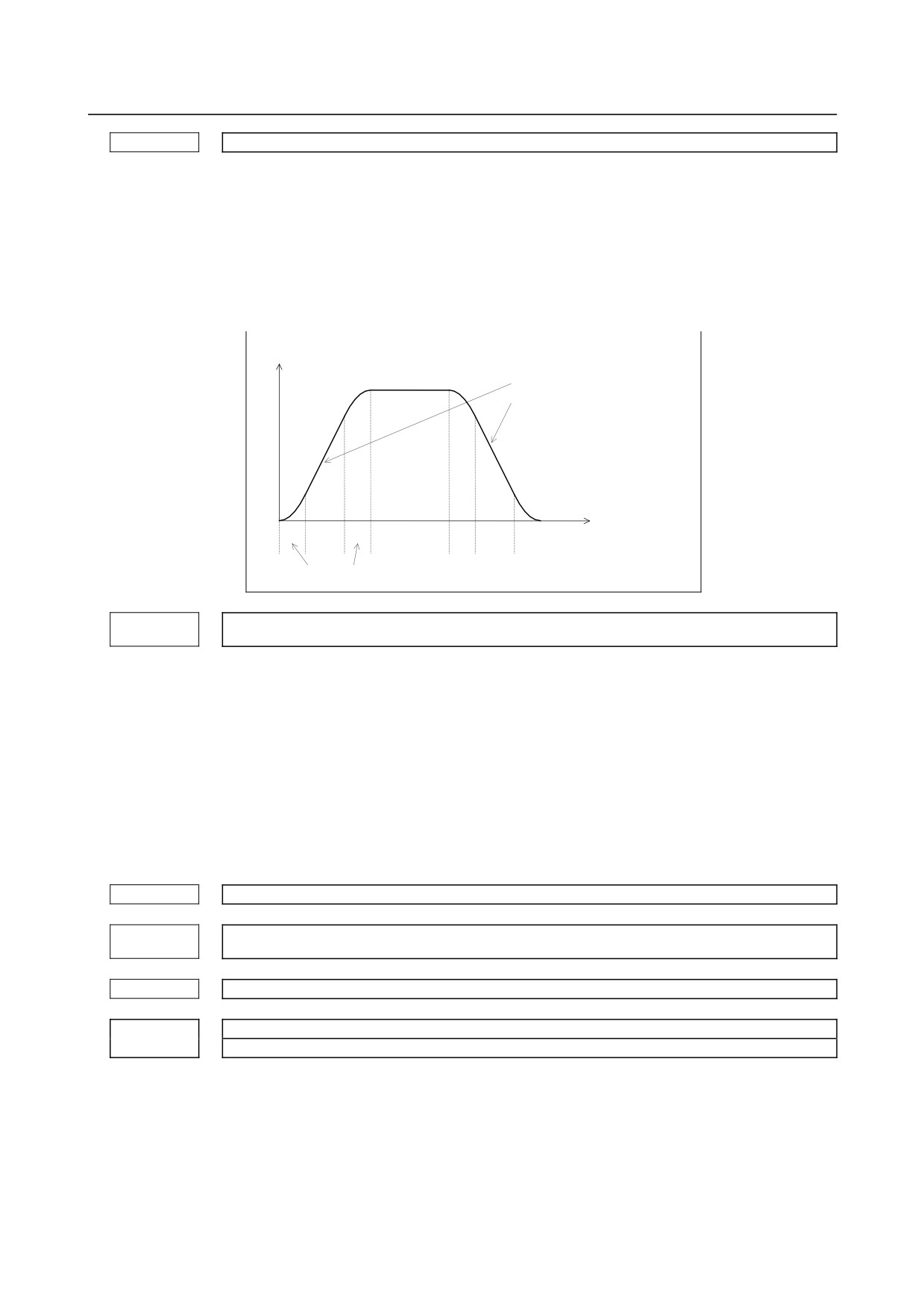
Acceleration change time of bell-shaped acceleration/deceleration before interpolation in rigid tapping
[Input type] Parameter input
[Data type] 2-word path
[Unit of data] msec
[Valid data range] 0 to 200
Set an acceleration change time of bell-shaped acceleration/ deceleration before
interpolation (time for changing from the state of constant federate (A) to the state of
constant acceleration/deceleration
(C) at the acceleration rate calculated from the
acceleration rate set in parameter No. 11050: time of (B) in the figure below).
Speed in tangent direction
Based on the setting of parameter
No. 11050, an optimum inclination
is calculated automatically.
(A)
(B)
(C)
(B)
(A)
(B)
(C)
(B)
(A)
Set time in parameter No. 11051.
Time constant for acceleration/deceleration after cutting feed interpolation in the
11052
acceleration/deceleration before interpolation mode in rigid tapping
[Input type] Parameter input
[Data type] Word axis
[Unit of data] msec
[Valid data range] 0 to 4000
In the acceleration/deceleration before interpolation mode as in advanced preview control,
not the ordinary time constant (parameter No. 1622) but the value of this parameter is
used.
Be sure to specify the same time constant value for all axes except for a special
application.
If different values are set, correct linear and circular figures cannot be obtained.
11060
Time constant for acceleration/deceleration after cutting feed interpolation in rigid tapping (first gear)
Time constant for acceleration/deceleration after cutting feed interpolation in rigid tapping (second
11061
gear)
11062
Time constant for acceleration/deceleration after cutting feed interpolation in rigid tapping (third gear)
Time constant for acceleration/deceleration after cutting feed interpolation in rigid tapping (fourth gear)
11063
[Input type] Parameter input
[Data type] Word axis
[Unit of data] msec
[Valid data range] 0 to 4000
Set the time constant of rigid tapping with servo motor in these parameters (Nos. 11060
to 11063).
Set these parameters with the servo motor spindle in rigid tapping.
- 376 -
B-64310EN/02
4.DESCRIPTION OF PARAMETERS
Time constant for acceleration/deceleration deceleration after cutting feed interpolation in rigid tapping
11065
extraction (first gear)
Time constant for acceleration/deceleration deceleration after cutting feed interpolation in rigid tapping
11066
extraction (second gear)
Time constant for acceleration/deceleration deceleration after cutting feed interpolation in rigid tapping
11067
extraction (third gear)
Time constant for acceleration/deceleration deceleration after cutting feed interpolation in rigid tapping
11068
extraction (fourth gear)
[Input type] Parameter input
[Data type] Word axis
[Unit of data] msec
[Valid data range] 0 to 4000
When bit 2 (TDR) of parameter No. 5201 is set to 1, time constants for extraction of rigid
tapping with servo motor can be set in these parameters (Nos. 11065 to 11068).
Set these parameters with the servo motor spindle in rigid tapping.
Path number with which the rotation of each spindle is specified
11090
[Input type] Parameter input
[Data type] Byte spindle
[Valid data range] 0 to 2
When a path is specified for spindle commands, this parameter sets a path number with
which the rotation of a spindle can be specified.
0: Spindle commands can be issued from both paths.
1 to 2:
Spindle commands can be issued from a set path.
NOTE
1 This parameter is valid when SPSP<Gn536.7> is set to 1.
2 If the setting is illegal, an alarm (PS5305) is issued when a spindle
command is issued from any one of the paths.
3 This setting does not apply to spindle commands using the spindle
select signals (SWS1 and SWS2<Gn027.0 and 1>).
4.65 PARAMETERS OF INCH/METRIC CONVERSION AND
DIAMETER/RADIUS SWITCHING (1 OF 2)
#7
#6
#5
#4
#3
#2
#1
#0
11222
CIM
NIM
[Input type] Parameter input
[Data type] Bit path
#0 NIM Automatic conversion of a coordinate system by an inch/metric conversion command
(G20 or G21) is:
0: Not performed.
1: Performed.
- 377 -
4.DESCRIPTION OF PARAMETERS
B-64310EN/02
#1 CIM When an inch/metric conversion command (G20 or G21) is specified, if the workpiece
coordinate system is shifted by the shift amount as described below:
0: An alarm (PS1298) is issued.
1: Clearing is performed.
This parameter is valid when bit 0 (NIM) of parameter No. 11222 is 1 or bit 2 (IRF) of
parameter No. 14000 is 1 and clears the following items.:
• Manual intervention made when the manual absolute signal is off
• Issuance of a move command with the machine locked
• Movement by handle interrupt
• Operation with a mirror image
• Shifting of a workpiece coordinate system when a local coordinate system or
workpiece coordinate system is set up
4.66 PARAMETERS OF DI/DO (2 OF 2)
#7
#6
#5
#4
#3
#2
#1
#0
OPS
TRS
11223
OPS
[Input type] Parameter input
[Data type] Bit path
#1 TRS In threading cycle retraction, when a block that specifies return to the start point of the
threading cycle is executed, threading signal THRD is:
0: Set to 0.
1: Set to 1.
#2 OPS In the MEM mode, when a sequence number search operation ([N SEARCH]) is
performed, automatic operation signal OP<F000.7> is:
0: Kept 0.
1: Set to 1.
4.67 PARAMETERS OF FEEDRATE CONTROL AND
ACCELERATION/DECELERATION CONTROL
#7
#6
#5
#4
#3
#2
#1
#0
11240
AMP
[Input type] Parameter input
[Data type] Bit path
#1 AMP Movement from the midpoint to the reference position by the G28 or G30 command or
movement by the G53 command in the advance preview control/AI advance preview
control/AI contour control mode uses:
0: Acceleration/deceleration after interpolation.
1: Acceleration/deceleration before interpolation.
- 378 -

B-64310EN/02
4.DESCRIPTION OF PARAMETERS
NOTE
The setting of this parameter is valid when the following conditions
are met.
1 Bit 4 (ZRL) of parameter No. 1015 is 1 (G28, G30, and G53
must be interpolation commands).
2 Bit 1 (LRP) of parameter No. 1401 is 1 (interpolation positioning
is enabled).
3 Parameter No. 1671 (maximum acceleration during rapid
traverse) is set.
4 Bit 5 (FRP) of parameter No. 19501 is 1
(acceleration/deceleration before interpolation is valid for rapid
traverse).
To enable blinking display and signal output indicating the advance
preview control/AI advance preview control/AI contour control
mode even when G28, G30, or G53 is specified, set bit 1 (AIR) of
parameter No. 1612 to 1 in addition to the above settings.
4.68 PARAMETERS OF COORDINATE SYSTEM
11275
The top number of M code used to turn on each axis workpiece coordinate system preset signal
[Input type] Parameter input
[Data type] 2-word path
[Valid data range] 1 to 99999999
Specify the top number of M code for turning “1” each axis workpiece coordinate system
preset signal (Gn358) during automatic operation.
When the specified M codes are within the range specified with this parameter and
parameter No.11276, each axis workpiece coordinate system preset signal is checked and
preset workpiece coordinate system for axis that the signal is turned “1”.
The specified M codes prevent buffering.
NOTE
When each axis workpiece coordinate system preset signals are
turned “1” more than two signals by an M code, please turn “1” the
signals of all axis at the same timing. If the timing is different, only
the axis of the first signal turned “1” is preset.
If you want to turn “1” the signals at the different timing, please
specify M code separately.
11276
The number of M code used to turn on each axis workpiece coordinate system preset signal
[Input type] Parameter input
[Data type] Word path
[Valid data range] 1 to 999
Specify the number of M code for turning “1” each axis workpiece coordinate system
preset signal (Gn358) during automatic operation.
For example, when parameter No.11275 = 100 and parameter No.11276 = 10 are set,
From M100 to M109 are used for turning “1” each axis workpiece coordinate system
preset signal.
When 0 is set, the number of M code is assumed to be 1.
- 379 -
4.DESCRIPTION OF PARAMETERS
B-64310EN/02
NOTE
Set only M code that is not used for another function.
(M00 to 05,30,98,99, 198 M code used to call the subprogram, etc.)
#7
#6
#5
#4
#3
#2
#1
#0
11277
PWR
WPA
[Input type] Parameter input
[Data type] Bit path
#0 WPA When an M code for turning on the workpiece coordinate system preset signal for an axis
is specified, but the signal is not turned on, or an auxiliary function lock is provided:
0: An alarm (PS1820) is issued.
1: An alarm is not issued.
#5 PWR When bit 3 (PPD) of parameter No.3104 is set to 0, the relative coordinate value is
0: Preset to 0.
1: Preset to the machine coordinate value.
NOTE
This parameter is valid only when bit 3 (PPD) of parameter
No.3104 is set to 0.
#7
#6
#5
#4
#3
#2
#1
#0
11278
WMC
NOTE
When this parameter is set, the power must be turned off before
operation is continued.
[Input type] Parameter input
[Data type] Bit path
#0 WMC In the "direct input of workpiece origin offset value measured", the workpiece origin
offset value is
0: calculated based on the absolute coordinate value.
Workpiece origin offset value =
Absolute coordinate value before measurement - Measured value
+ Selected workpiece origin offset value
+ External workpiece origin offset value
1: calculated based on the machine coordinate value. (FS0i-C compatible specification)
Workpiece origin offset value = Machine coordinate value - Measured value
#7
#6
#5
#4
#3
#2
#1
#0
MWK
11284
[Input type] Parameter input
[Data type] Bit
- 380 -
B-64310EN/02
4.DESCRIPTION OF PARAMETERS
#7 MWK When the workpiece coordinate system is valid (when bit 0 (NWZ) of parameter No.8136
is 0), the behavior of the coordinate system setting when the composite control is begun
or ended is:
0: The FS0i-D specification. (The preset which corresponds to G92.1 is performed.)
1: The FS0i-C specification.
4.69 PARAMETERS OF DISPLAY AND EDIT (2 OF 5)
#7
#6
#5
#4
#3
#2
#1
#0
11300
MUC
ATH
MPH
ASH
[Input type] Parameter input
[Data type] Bit
#3 ASH When the actual feedrate is read with FOCAS2 and the PMC window:
0: Data that has been updated at conventional intervals (approximately 32 ms) is read.
1: Data that has been updated at short intervals is read.
If this parameter is set to 1, the machine coordinates of the machine unit with the delay in
acceleration/deceleration and the servo delay considered are read for all axes, regardless
of the setting of bit 7 (EMP) of parameter No. 11313.
NOTE
When quick response is not required in particular for display
operation and so on, normally set this parameter to 0 to reduce the
load on the CNC.
#5 MPH When the machine coordinates of the machine unit with the delay in
acceleration/deceleration and the servo delay not considered are read with FOCAS2 and
the PMC window:
0: Data that has been updated at conventional intervals (approximately 32 ms) is read.
1: Data that has been updated at short intervals is read.
NOTE
When quick response is not required in particular for display
operation and so on, normally set this parameter to 0 to reduce the
load on the CNC.
#6 ATH When the disturbance load torque data are read with FOCAS2 and the PMC window:
0: Data that has been updated at conventional intervals (approximately 32 ms) is read.
1: Data that has been updated at short intervals is read.
NOTE
When quick response is not required in particular for display
operation and so on, normally set this parameter to 0 to reduce the
load on the CNC.
#7 MUC When the modal data are read with FOCAS2 and the PMC window:
0: Data that has been updated at conventional intervals (approximately 32 ms) is read.
1: Data that has been updated at short intervals is read.
- 381 -
4.DESCRIPTION OF PARAMETERS
B-64310EN/02
NOTE
When quick response is not required in particular for display
operation and so on, normally set this parameter to 0 to reduce the
load on the CNC.
#7
#6
#5
#4
#3
#2
#1
#0
11302
CPG
PES
ADC
SMD
SDG
SPR
SPG
[Input type] Parameter input
[Data type] Bit
#0 SPG Initially, the program screen is:
0: Displayed full-screen.
1: Displayed in a window.
#1 SPR Initially, the parameter screen is:
0: Displayed full-screen.
1: Displayed in a window.
#2 SDG Initially, the diagnosis screen is:
0: Displayed full-screen.
1: Displayed in a window.
#3 SMD The MDI program screen is:
0: Displayed according to the setting of bit 0 (SPG) of parameter No. 11302.
1: Displayed in a window.
If this parameter is set to 0, the first display mode entered after the power is turned on is
determined according to the setting of bit 0 (SPG) of parameter No. 11302. Depending on
the display mode, the MDI program screen is displayed full-screen or in a window. Also,
the screen display can be dynamically switched between the full-screen mode and the
window mode by interacting with the program screen in another mode.
If this parameter is set to 1, the MDI program screen is always displayed in a window,
and it is impossible to switch between the full-screen mode and the window mode by
operations.
#4 ADC When all alarms have been eliminated, or the message key is pressed on the alarm screen:
0: The screen display does not change.
1: The screen display changes to the screen displayed before the alarm screen.
#5 PES After a program search operation is performed on the program list screen:
0: The cursor moves to a program on the list screen.
1: A specified program is selected as the main program, and the screen display changes
to the edit screen.
#7 CPG PROG function screen selection is:
0: Not changed according to the CNC mode.
1: Changed according to the CNC mode.
#7
#6
#5
#4
#3
#2
#1
#0
11303
ISQ
DPM
BDP
LDP
[Input type] Parameter input
- 382 -