FANUC Series 0i-MODEL D, Series 0i Mate-MODEL D. PARAMETER MANUAL - page 15
B-64310EN/02
4.DESCRIPTION OF PARAMETERS
13266
D code for enabling cutter compensation in tool life management
[Input type] Parameter input
[Data type] 2-word path
[Valid data range] 0 to 9999
Setting this parameter to D99 generally validates the compensation for the tool currently
being used. By setting any D code in this parameter, the D code instead of D99 can be
used. If 0 is set, D99 is assumed.
4.87 PARAMETERS OF THE MACHINING CONDITION
SELECTION FUNCTION
#7
#6
#5
#4
#3
#2
#1
#0
MCR
13600
MSA
MCR
[Input type] Parameter input
[Data type] Bit path
#0 MCR When an allowable acceleration rate adjustment is made with the machining condition
selection function
(machining parameter adjustment screen, precision level selection
screen), parameter No.
1735 for the deceleration function based on acceleration in
circular interpolation is:
0: Modified.
1: Not modified.
#7 MSA When the machining condition selection function is used, the acceleration rate change
time (bell-shaped) (LV1, LV10) is:
0: Set using parameter Nos. 13612 and 13613.
1: Set using parameter Nos. 13662 and 13663.
#7
#6
#5
#4
#3
#2
#1
#0
13601
MPR
[Input type] Parameter input
[Data type] Bit
NOTE
When this parameter is set, the power must be turned off before
operation is continued.
#0 MPR The machining parameter adjustment screen is:
0: Displayed.
1: Not displayed.
Even when this parameter is set to 1, the precision level selection screen is displayed.
Acceleration rate for acceleration/deceleration before look-ahead interpolation in advanced preview
13610
control/AI advanced preview control/AI contour control/AI contour control II (precision level 1)
Acceleration rate for acceleration/deceleration before look-ahead interpolation in advanced preview
13611
control/AI advanced preview control/AI contour control/AI contour control II (precision level 10)
[Input type] Parameter input
- 413 -
4.DESCRIPTION OF PARAMETERS
B-64310EN/02
[Data type] Real axis
[Unit of data] mm/sec/sec, inch/sec/sec, degree/sec/sec (machine unit)
[Min. unit of data] Depend on the increment system of the applied axis
[Valid data range] Refer to the standard parameter setting table (D)
(When the machine system is metric system, 0.0 to +100000.0. When the machine system
is inch system, machine, 0.0 to +10000.0)
Each of these parameters sets an acceleration rate for acceleration/ deceleration before
interpolation in advanced preview control/AI advanced preview control/AI contour
control/AI contour control II. Set a value (precision level 1) with emphasis placed on
speed, and a value (precision level 10) with emphasis on precision.
13612
Acceleration rate change time (bell-shaped) when AI contour control/AI contour control II is used
(precision level 1)
13613
Acceleration rate change time (bell-shaped) when AI contour control/AI contour control II is used
(precision level 10)
[Input type] Parameter input
[Data type] Byte path
[Unit of data] msec
[Valid data range] 0 to 127
Each of these parameters sets an acceleration rate change time (bell-shaped) in AI contour
control/AI contour control II. Set a value (precision level 1) with emphasis placed on
speed, and a value (precision level 10) with emphasis on precision.
13614
Allowable acceleration rate change amount for each axis in speed control based on acceleration rate
change under control on the rate of change of acceleration (precision level 1)
13615
Allowable acceleration rate change amount for each axis in speed control based on acceleration rate
change under control on the rate of change of acceleration (precision level 10)
[Input type] Parameter input
[Data type] Real axis
[Unit of data] mm/sec/sec, inch/sec/sec, degree/sec/sec (machine unit)
[Min. unit of data] Depend on the increment system of the applied axis
[Valid data range] Refer to the standard parameter setting table (D)
(When the machine system is metric system, 0.0 to +100000.0. When the machine system
is inch system, machine, 0.0 to +10000.0)
Each of these parameters sets an allowable acceleration rate change amount per 1 ms for
each axis in speed control based on acceleration rate change under control on the rate of
change of acceleration during AI contour control II.
Set a value (precision level 1) with emphasis placed on speed, and a value (precision level
10) with emphasis on precision.
- 414 -
B-64310EN/02
4.DESCRIPTION OF PARAMETERS
Allowable acceleration rate change amount for each axis in speed control based on acceleration rate
13616
change under control on the rate of change of acceleration in successive linear interpolation
operations (precision level 1)
Allowable acceleration rate change amount for each axis in speed control based on acceleration rate
13617
change under control on the rate of change of acceleration in successive linear interpolation
operations (precision level 10)
[Input type] Parameter input
[Data type] Real axis
[Unit of data] mm/sec/sec, inch/sec/sec, degree/sec/sec (machine unit)
[Min. unit of data] Depend on the increment system of the applied axis
[Valid data range] Refer to the standard parameter setting table (D)
(When the machine system is metric system, 0.0 to +100000.0. When the machine system
is inch system, machine, 0.0 to +10000.0)
Each of these parameters sets an allowable acceleration rate change amount per 1 ms for
each axis in speed control based on acceleration rate change under control on the rate of
change of acceleration in successive linear interpolation operations during AI contour
control II.
Set a value (precision level 1) with emphasis placed on speed, and a value (precision level
10) with emphasis on precision.
NOTE
1 For an axis with 0 set in this parameter, parameter No. 13614 and
No. 13615 (allowable acceleration rate change amount in speed
control based on acceleration rate change under control on the rate
of change of acceleration) are valid.
2 For an axis with 0 set in parameter No. 13614 and No. 13615
(allowable acceleration rate change amount in speed control based
on acceleration rate change under control on the rate of change of
acceleration), speed control based on acceleration rate change is
disabled, so that the specification of this parameter has no effect.
13618
Rate of change time of the rate of change of acceleration in smooth bell-shaped
acceleration/deceleration before interpolation when AI contour control II is used (precision level 1)
13619
Rate of change time of the rate of change of acceleration in smooth bell-shaped
acceleration/deceleration before interpolation when AI contour control II is used (precision level 10)
[Input type] Parameter input
[Data type] Byte path
[Unit of data] %
[Valid data range] 0 to 50
Each of these parameters sets the rate (percentage) of the change time of the rate of
change of acceleration to the change time of acceleration rate change in smooth
bell-shaped acceleration/deceleration before look-ahead interpolation during AI contour
control II.
Set a value (precision level 1) with emphasis placed on speed, and a value (precision level
10) with emphasis on precision.
- 415 -
4.DESCRIPTION OF PARAMETERS
B-64310EN/02
NOTE
When 0 or a value not within the valid data range is set in this
parameter, smooth bell-shaped acceleration/deceleration before
look-ahead interpolation is not performed.
Allowable acceleration rate when advanced preview control/AI advanced preview control/AI contour
13620
control/AI contour control II is used (precision level 1)
Allowable acceleration rate when advanced preview control/AI advanced preview control/AI contour
13621
control/AI contour control II is used (precision level 10)
[Input type] Parameter input
[Data type] Real axis
[Unit of data] mm/sec/sec, inch/sec/sec, degree/sec/sec (machine unit)
[Min. unit of data] Depend on the increment system of the applied axis
[Valid data range] Refer to the standard parameter setting table (D)
(When the machine system is metric system, 0.0 to +100000.0. When the machine system
is inch system, machine, 0.0 to +10000.0)
Each of these parameters sets an allowable acceleration rate in advanced preview
control/AI advanced preview control/AI contour control/AI contour control II. Set a value
(precision level 1) with emphasis placed on speed, and a value (precision level 10) with
emphasis on precision.
Time constant for acceleration/deceleration after interpolation when advanced preview control/AI
13622
advanced preview control/AI contour control/AI contour control II is used (precision level 1)
Time constant for acceleration/deceleration after interpolation when advanced preview control/AI
13623
advanced preview control/AI contour control/AI contour control II is used (precision level 10)
[Input type] Parameter input
[Data type] Word axis
[Unit of data] msec
[Valid data range] 1 to 512
Each of these parameters sets a time constant for acceleration/ deceleration after
interpolation when advanced preview control/AI advanced preview control/AI contour
control/AI contour control II is used. Set a value (precision level 1) with emphasis placed
on speed, and a value (precision level 10) with emphasis on precision.
Corner speed difference when advanced preview control/AI advanced preview control/AI contour/AI
13624
contour control II control is used (precision level 1)
Corner speed difference when advanced preview control/AI advanced preview control/AI contour/AI
13625
contour control II control is used (precision level 10)
[Input type] Parameter input
[Data type] Real axis
[Unit of data] mm/min, inch/min, degree/min (machine unit)
[Min. unit of data] Depend on the increment system of the applied axis
[Valid data range] Refer to the standard parameter setting table (C)
(When the increment system is IS-B, 0.0 to +999000.0)
Each of these parameters sets an allowable speed difference for speed determination
based on corner speed difference in advanced preview control/AI advanced preview
control/AI contour control/AI contour control II. Set a value (precision level 1) with
emphasis placed on speed, and a value (precision level 10) with emphasis on precision.
- 416 -
B-64310EN/02
4.DESCRIPTION OF PARAMETERS
Maximum cutting speed when advanced preview control/AI advanced preview control/AI contour
13626
control/AI contour control II is used (precision level 1)
Maximum cutting speed when advanced preview control/AI advanced preview control/AI contour
13627
control/AI contour control II is used (precision level 10)
[Input type] Parameter input
[Data type] Real axis
[Unit of data] mm/min, inch/min, degree/min (machine unit)
[Min. unit of data] Depend on the increment system of the applied axis
[Valid data range] Refer to the standard parameter setting table (C)
(When the increment system is IS-B, 0.0 to +999000.0)
Each of these parameters sets a maximum cutting speed in advanced preview control/AI
advanced preview control/AI contour control/AI contour control II. Set a value (precision
level 1) with emphasis placed on speed, and a value (precision level 10) with emphasis on
precision.
Parameter number corresponding to arbitrary item 1 when advanced preview control/AI advanced
13628
preview control/AI contour control/AI contour control II is used
Parameter number corresponding to arbitrary item 2 when advanced preview control/AI advanced
13629
preview control/AI contour control/AI contour control II is used
NOTE
When these parameters are set, the power must be turned off before
operation is continued.
[Input type] Parameter input
[Data type] 2-word path
[Valid data range] 1 to 65535
These parameters set the parameter numbers corresponding to arbitrary items 1 and 2.
NOTE
The parameter numbers corresponding to the following cannot be
specified:
• Bit parameters
• Spindle parameters (No. 4000 to No. 4799)
• Parameters of real number type
• Parameters that require power-off (for which the alarm
(PW0000) is issued)
• Nonexistent parameters
Value with emphasis on speed (precision level 1) of the parameter corresponding to arbitrary item 1
13630
when advanced preview control/AI advanced preview control/AI contour control/AI contour control II is
used
Value with emphasis on speed (precision level 1) of the parameter corresponding to arbitrary item 2
13631
when advanced preview control/AI advanced preview control/AI contour control/AI contour control II is
used
Value with emphasis on speed (precision level 10) of the parameter corresponding to arbitrary item 1
13632
when advanced preview control/AI advanced preview control/AI contour control/AI contour control II is
used
- 417 -
4.DESCRIPTION OF PARAMETERS
B-64310EN/02
Value with emphasis on speed (precision level 10) of the parameter corresponding to arbitrary item 2
13633
when advanced preview control/AI advanced preview control/AI contour control/AI contour control II is
used
[Input type] Parameter input
[Data type] 2-word axis
[Unit of data] Depend on the type of parameter for an arbitrary item
[Valid data range] Depend on the type of parameter for an arbitrary item
Each of these parameters sets a value with emphasis placed on speed or precision for a
parameter.
Precision level currently selected when advanced preview control/AI advanced preview control/AI
13634
contour/AI contour control II control is used
[Input type] Parameter input
[Data type] Byte path
[Valid data range] 1 to 10
This parameter sets the level currently selected.
13662
Acceleration rate change time (bell-shaped) when AI contour control/AI contour control II is used
(precision level 1), range extended
13663
Acceleration rate change time (bell-shaped) when AI contour control/AI contour control II is used
(precision level 10), range extended
[Input type] Parameter input
[Data type] 2-word path
[Unit of data] msec
[Valid data range] 0 to 200
Each of these parameters sets an acceleration rate change time (bell-shaped) in AI contour
control/AI contour control II. Set a value (precision 1) with emphasis placed on speed,
and a value (precision level 10) with emphasis on precision.
4.88 PARAMETERS OF PARAMETER CHECK SUM
#7
#6
#5
#4
#3
#2
#1
#0
13730
CSR
CKS
[Input type] Parameter input
[Data type] Bit axis
#0 CKS During power-on, a checksum of parameters is:
0: Not checked.
1: Checked.
#7 CSR Alarm DS5340 parameter checksum error is:
0: Cleared by the "CAN" + "RESET" operation.
1: Cleared by the "RESET" operation.
- 418 -
B-64310EN/02
4.DESCRIPTION OF PARAMETERS
13731
NC parameter checksum exclusion number 01
to
to
13750
NC parameter checksum exclusion number 20
[Input type] Parameter input
[Data type] 2-word
[Valid data range] 0 to Maximum parameter number
This parameter sets the numbers of parameters to be excluded from a checksum
performed by the parameter checksum function.
13751
NC parameter checksum exclusion range start number 01
13752
NC parameter checksum exclusion range end number 01
to
to
13769
NC parameter checksum exclusion range start number 10
13770
NC parameter checksum exclusion range end number 10
[Input type] Parameter input
[Data type] 2-word
[Valid data range] 0 to Maximum parameter number
This parameter specifies the range of the numbers of parameters to be excluded from a
checksum performed by the parameter checksum function. The parameters included in
the range is excluded from a checksum.
NOTE
1 The start number and end number are included in the exclusion
range.
2 If the start number is greater than the end number (start number >
end number), the checksum exclusion number setting is invalid.
3 If the start number is equal to the end number (start number = end
number), only the number is excluded.
4.89 PARAMETERS OF INCH/METRIC CONVERSION AND
DIAMETER/RADIUS SWITCHING (2 OF 2)
#7
#6
#5
#4
#3
#2
#1
#0
14000
IMAx
IRFx
[Input type] Parameter input
[Data type] Bit axis
NOTE
When at least one of these parameters is set, the power must be
turned off before operation is continued.
#2 IRFx An inch-metric switch command (G20, G21) at the reference position is:
0: Disabled.
1: Enabled.
- 419 -

4.DESCRIPTION OF PARAMETERS
B-64310EN/02
When this function is enabled for an axis, if an attempt to switch between the inch and
metric unit is made although the tool is not at the reference position on that axis, an alarm
(PS5362) is issued, and switching between the inch and metric unit is canceled.
Be sure to move the tool to the reference position by, for example, specifying G28 before
switching between the inch and metric unit.
NOTE
1 This function enables the inch/metric switching commands (G20
and G21) at the reference position. It does not enable the
switching of the setting input unit (bit 2 (INI) of parameter No.
0000).
2 Swithching between inch and metric by setting the setting input unit
(bit 2 (INI) of parameter No. 0000) is enabled only when the
machine coordinate of the first reference position is 0 (parameter
No. 1240 is 0) and presence on the first reference position is
assumed.
For a system in which the machine coordinate of the first reference
position is not 0, set this parameter to 1 and specify G20/G21 in the
first reference position to switch between inch and metric.
#7
IMAx When switching between inch and millimeter was performed in a position other than the
reference position:
0: An alarm occurs.
1: No alarm occurs.
NOTE
Set this parameter to 1 for the rotation axis or other axes not
related to inch/millimeter switching.
4.90 PARAMETERS OF LINEAR SCALE WITH ABSOLUTE
ADDRESS REFERENCE POSITION
Maximum allowable travel distance when the reference position is established for a linear scale with an
14010
absolute address reference position
[Input type] Parameter input
[Data type] 2-word axis
[Unit of data] Detection unit
[Valid data range] 0 to 99999999
This parameter sets the maximum allowable travel distance at the FL feedrate when the
reference position is established for a linear scale with an absolute address reference
position. When the travel distance exceeds the setting of this parameter, the alarm
(DS0017)
(SCALE WITH REFERENCE POSITION: REFERENCE POSITION
ESTABLISHMENT FAILED) is issued. When this parameter is set to 0, the maximum
allowable travel distance is not checked.
- 420 -

B-64310EN/02
4.DESCRIPTION OF PARAMETERS
4.91 PARAMETERS OF FSSB
14340
ATR value corresponding to slave 01 on FSSB
to
to
14357
ATR value corresponding to slave 18 on FSSB
NOTE
When these parameters are set, the power must be turned off before
operation is continued.
[Input type] Parameter input
[Data type] Byte
[Valid data range] 0 to 7,64,-56,-96
Each of these parameters sets the value (ATR value) of the address translation table
corresponding to each of slave 1 to slave 18 on FSSB.
The slave is a generic term for servo amplifiers and separate detector interface units
connected via an FSSB optical cable to the CNC. Numbers 1 to 18 are assigned to slaves,
with younger numbers sequentially assigned to slaves closer to the CNC.
A 2-axis amplifier consists of two slaves, and a 3-axis amplifier consists of three slaves.
In each of these parameters, set a value as described below, depending on whether the
slave is an amplifier, separate detector, or nonexistent.
• When the slave is an amplifier:
Set a value obtained by subtracting 1 from the setting of parameter No. 1023 for the
axis to which the amplifier is assigned.
• When the slave is a separate detector interface unit:
Set 64 for the first separate detector interface unit (connected near the CNC), and set
-56 for the second separate detector interface unit (connected far from the CNC).
• When the slave is nonexistent:
Set -96.
NOTE
1 When the electric gear box (EGB) function is used
Although an amplifier is not actually required for an EGB dummy
axis, set this parameter with assuming that a dummy amplifier is
connected. That is, as the address conversion table value for a
nonexistent slave, set the value obtained by subtracting 1 from the
setting of parameter No. 1023 for the EGB dummy axis, instead of
-96.
2 When the FSSB is set to the automatic setting mode (when the
parameter FMD (No.1902#0) is set to 0), parameter Nos. 14340 to
14357 are automatically set as data is input on the FSSB setting
screen. When the manual setting 2 mode is set (when the
parameter FMD (No.1902#0) is set to 1), be sure to directly set
values in parameter Nos. 14340 to 14357.
- 421 -
4.DESCRIPTION OF PARAMETERS
B-64310EN/02
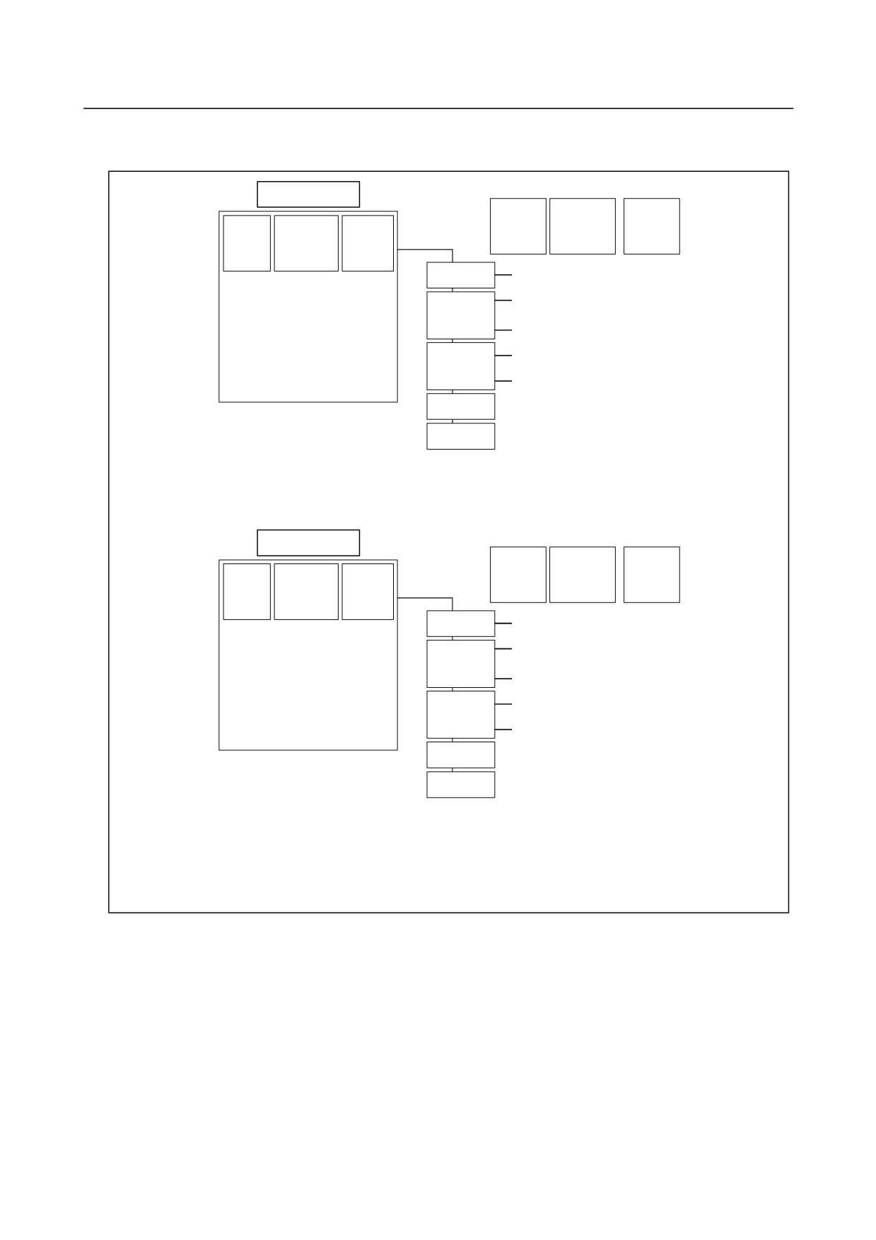
Example of axis configuration and parameter settings
-
Example 1
CNC
Slave
ATR
number
No.14340
Controll
Program
Servo
Axis
to 14357
ed axis
axis name
axis
number
No.1020
No.1023
Single-axis
1
0
X
1
X
1
amplifier
2
1
A
2
Y
3
Two-axis
amplifier
3
Z
4
3
2
Y
4
A
2
Two-axis
4
3
Z
amplifier
5
B
5
5
4
B
M1
6
64
(M1)
M2
7
-56
(M2)
8 to 18
-96
(None)
CNC
Slave
ATR
number
No.14340
Controll
Program
Servo
Axis
to 14357
ed axis
axis name
axis
number
No.1020
No.1023
Single-axis
1
0
X
1
X
1
amplifier
2
2
Y
2
Y
3
Two-axis
amplifier
3
Z
4
3
3
Z
4
A
2
Two-axis
4
1
A
amplifier
5
B
5
5
4
B
M1
6
64
(M1)
M2
7
-56
(M2)
8 to 18
-96
(None)
M1/M2: First/second separate detector interface units
- 422 -
B-64310EN/02
4.DESCRIPTION OF PARAMETERS
-
Example 2
Example of axis configuration and parameter settings when the electronic gear box (EGB) function is
used
(EGB slave axis: A-axis, EGB dummy axis: B-axis)
CNC
ATR
Slave
Controlled
Program
Servo
No.14340
Axis
number
axis
axis
axis
to 14357
number
name
No.1023
No.1020
Single-axis
1
0
X
1
X
1
amplifier
2
1
Y
2
Y
2
Two-axis
amplifier
3
Z
5
3
2
A
Single-axis
4
A
3
4
4
Z
amplifier
5
B
4
M1
5
64
(M1)
M2
6
-56
(M2)
7
3
B(Dummy)
8 to 18
-96
(None)
M1/M2: First/second separate detector interface units
14376
ATR value corresponding to connector 1 on the first separate detector interface unit
to
to
14383
ATR value corresponding to connector 8 on the first separate detector interface unit
14384
ATR value corresponding to connector 1 on the second separate detector interface unit
to
to
14391
ATR value corresponding to connector 8 on the third separate detector interface unit
NOTE
When these parameters are set, the power must be turned off before
operation is continued.
[Input type] Parameter input
[Data type] Byte
[Valid data range] 0 to 7, 32
Each of these parameters sets the value (ATR value) of the address translation table
corresponding to each connector on a separate detector interface unit.
In each of these parameters, set a value obtained by subtracting 1 from the setting of
parameter No. 1023 for the axis connected to a connector on a separate detector interface
unit.
When there are axes for which settings are made to use a separate detector interface unit
(bit 6 (PM1x) of parameter No. 1905 is set to 1 or bit 7 (PM2x) of parameter No. 1905 is
set to 1, set 32 for connectors not used.
- 423 -
4.DESCRIPTION OF PARAMETERS
B-64310EN/02
NOTE
When the FSSB is set to the automatic setting mode (when the
parameter FMD (No.1902#0) is set to 0), parameter Nos. 14376 to
14391 are automatically set as data is input on the FSSB setting
screen. When the manual setting 2 mode is set (when the
parameter FMD (No.1902#0) is set to 1), be sure to directly set
values in parameter Nos. 14376 to 14407.
#7
#6
#5
#4
#3
#2
#1
#0
14476
DFS
NOTE
When this parameter is set, the power must be turned off before
operation is continued.
[Input type] Parameter input
[Data type] Bit
#0 DFS The FSSB enters:
0: The FS0i-D-specific mode.
1: The FS0i-C-compatible mode.
4.92 PARAMETERS OF GRAPHIC DISPLAY (3 OF 3)
14713
Unit of magnification by which enlargement and reduction is performed with the dynamic graphic
display function
[Input type] Parameter input
[Data type] Word
[Valid data range] 0 to 255
This parameter sets the unit of magnification by which enlargement and reduction is
performed with the dynamic graphic display function.
Unit of magnification = 64 / setting
If 0 is set, 64 is assumed.
14714
Unit of horizontal movement when a movement is made with the dynamic graphic display function
[Input type] Parameter input
[Data type] Word
[Valid data range] 0 to 255
This parameter sets the unit of horizontal movement (in dots) applied when a movement
is made with the dynamic graphic display function.
If 0 is set, 64 is assumed.
14715
Unit of vertical movement when a movement is made with the dynamic graphic display function
[Input type] Parameter input
[Data type] Word
[Valid data range] 0 to 255
- 424 -
B-64310EN/02
4.DESCRIPTION OF PARAMETERS
This parameter sets the unit of vertical movement (in dots) applied when a movement is
made with the dynamic graphic display function.
If 0 is set, 35 is assumed.
14716
Unit of rotation angle when rotation is performed with the dynamic graphic display function
[Input type] Parameter input
[Data type] Word
[Valid data range] 0 to 255
This parameter sets the unit (in degrees) of a rotation angle by which the drawing
coordinate system is rotated with the dynamic graphic display function.
If 0 is set, 10 is assumed.
14717
Axis number of the C-axis in simulation (specific to MANUAL GUIDE i)
[Input type] Parameter input
[Data type] Byte path
[Valid data range] 0 to Number of controlled axes
This parameter sets the axis number of the C-axis in simulation.
For details, refer to the FANUC MANUAL GUIDE i Common to Lathe
System/Machining Center System OPERATOR'S MANUAL (B-63874EN).
4.93 PARAMETERS OF EMBEDDED ETHERNET
#7
#6
#5
#4
#3
#2
#1
#0
14880
DHC
DNS
D1E
PCH
ETH
[Input type] Parameter input
[Data type] Bit
#0 ETH The embedded Ethernet function (a built-in port or PCMCIA LAN card) is:
0: Used.
1: Not used.
#1 PCH At the start of communication of the FTP file transfer function for built-in port, checking
for the presence of the server using PING is:
0: Performed.
1: Not performed.
NOTE
Usually, set 0.
If 1 is set not to check the presence of the server by using PING, it
may take several tens of seconds to recognize an error when the
server is not present in the network.
For mainly security reasons, a personal computer may be set so
that it does not respond to the PING command. To communicate
with such a personal computer, set 1.
- 425 -
4.DESCRIPTION OF PARAMETERS
B-64310EN/02
#3 D1E When the DHCP function on a built-in port is used:
0: Default parameters for the FOCAS2/Ethernet function are set.
PORT NUMBER (TCP)
: 8193
PORT NUMBER (UDP)
: 0
TIME INTERVAL
: 0
1: Default parameters for FANUC i CELL communication are set.
PORT NUMBER (TCP)
: 8193
PORT NUMBER (UDP)
: 8192
TIME INTERVAL
: 50
#5 DNS With a built-in port, the DNS client function is:
0: Not used.
1: Used.
#6 DHC With a built-in port, the DHCP client function is:
0: Not used.
1: Used.
14890
Selects the host computer 1 OS.
14891
Selects the host computer 2 OS.
14892
Selects the host computer 3 OS.
[Input type] Parameter input
[Data type] Word
[Valid data range] 0 to 2
0: Windows95/98/Me/2000/XP/Vista/7.
1: UNIX, VMS.
2: Linux.
NOTE
Some FTP server software products do not depend on the OS. So,
even when the above parameters are set, it is sometimes
impossible to display a list of files properly.
4.94 PARAMETERS OF MANUAL HANDLE RETRACE (2 OF 2)
18060
Backward movement prohibition M code that outputs no M code
[Input type] Parameter input
[Data type] Word path
[Valid data range] 1 to 999
When an M code that prohibits backward movement is specified during backward
movement, backward movement of blocks before the M code is prohibited. In this case,
backward movement prohibition signal MRVSP<Fn091.2> is output.
This backward movement prohibition M code is not output to the PMC as an M code.
Set an M code that is not used by an auxiliary function or macro as the backward
movement prohibition M code.
- 426 -
B-64310EN/02
4.DESCRIPTION OF PARAMETERS
18065
Backward movement prohibition M code 1 that outputs an M code
18066
Backward movement prohibition M code 2 that outputs an M code
[Input type] Parameter input
[Data type] Word path
[Valid data range] 1 to 999
When an M code that prohibits backward movement is specified during backward
movement, backward movement of blocks before the M code is prohibited. In this case,
backward movement prohibition signal MRVSP<Fn091.2> is output.
These backward movement prohibition M codes are output to the PMC as M codes. Set
M codes that are not used by an auxiliary function or macro as the backward movement
prohibition M codes.
4.95 PARAMETERS OF ADVANCED PREVIEW CONTROL / AI
ADVANCED PREVIEW CONTROL / AI CONTOUR
CONTROL / AI CONTOUR CONTROL II (2 OF 2)
#7
#6
#5
#4
#3
#2
#1
#0
19500
FCC
FNW
[Input type] Parameter input
[Data type] Bit path
#6 FNW In the speed determination method by the speed difference of advanced preview
control/AI advance preview control/AI contour control/AI contour control II and the
speed determination method by the acceleration of advanced preview control/AI contour
control/AI contour control II:
0: The maximum speed that does not exceed the allowable speed difference or
allowable acceleration is selected.
1: The feedrate is determined so that the allowable speed difference and allowable
acceleration of each axis are not exceeded and that the deceleration speed is constant
regardless of the movement direction if the shape is the same.
#7 FCC When there is an axis that requires one or more seconds for acceleration in
acceleration/deceleration before look-ahead interpolation:
0: Emphasis is placed on precision, so that the specified feedrate may not be reached.
1: Emphasis is placed on speed, so that the specified feedrate is produced.
When this parameter is set to 1, the precision of curved interpolation such as circular
interpolation may decrease.
#7
#6
#5
#4
#3
#2
#1
#0
19501
FRP
[Input type] Parameter input
[Data type] Bit path
#5 FRP linear-shaped rapid traverse in the advanced preview control/AI advance preview
control/AI contour control/AI contour control II mode is:
0: Acceleration/deceleration after interpolation.
1: Acceleration/deceleration before interpolation.
Set a maximum allowable acceleration rate for each axis in parameter No. 1671.
- 427 -
4.DESCRIPTION OF PARAMETERS
B-64310EN/02
When using bell-shaped acceleration/deceleration before interpolation, set an acceleration
rate change time in parameter No. 1672.
When this parameter is set to 1, acceleration/deceleration before interpolation is also
applied to rapid traverse if all conditions below are satisfied. At this time,
acceleration/deceleration after interpolation is not applied.
• Bit 1 (LRP) of parameter No. 1401 is set to 1: Linear interpolation type positioning
• A value other than 0 is set in parameter No. 1671 for an axis.
If all of these conditions are not satisfied, acceleration/deceleration after interpolation is
applied.
NOTE
To enable blinking display and signal output indicating the advance
preview control/AI advance preview control/AI contour control/AI
contour control II mode even when rapid traverse command is
specified, set bit 1 (AIR) of parameter No. 1612 to 1 in addition to
the above settings.
#7
#6
#5
#4
#3
#2
#1
#0
19503
ZOL
HPF
[Input type] Parameter input
[Data type] Bit path
#0 HPF When a feedrate is determined based on acceleration in AI contour control II, smooth
feedrate control is:
0: Not used.
1: Used.
#4 ZOL The deceleration function based on cutting load in AI contour control II (deceleration
based on Z-axis fall angle) is:
0: Enabled for all commands.
1: Enabled for linear interpolation commands only.
#7
#6
#5
#4
#3
#2
#1
#0
BEX
19515
ZG2
BEX
[Input type] Parameter input
[Data type] Bit path
#0 BEX When the tapping mode
(G63) or a conned cycle is specified, the mode for
acceleration/deceleration before look-ahead interpolation is:
0: Turned off.
1: Not turned off.
#1 ZG2 When the deceleration function based on cutting load in AI contour control II
(deceleration based on Z-axis fall angle) is used:
0: Stepwise override values are applied.
1: Inclined override values are applied.
This parameter is valid only when bit 4 (ZAG) of parameter No. 8451 is set to 1.
When this parameter is set to 1, be sure to set parameter Nos. 19516, 8456, 8457, and
8458.
- 428 -
B-64310EN/02
4.DESCRIPTION OF PARAMETERS
19516
Override for area 1 in deceleration based on cutting load in AI contour control II
[Input type] Parameter input
[Data type] Word path
[Unit of data] %
[Valid data range] 1 to 100
This parameter sets an override value for area 1 when the deceleration function based on
cutting load in AI contour control II is used.
This parameter is valid only when bit 1 (ZG2) of parameter No. 19515 is set to 1.
4.96 PARAMETERS OF NANO SMOOTHING (M SERIES)
19581
Tolerance smoothing for Nano smoothing
[Input type] Setting input
[Data type] Real path
[Unit of data] mm, inch, degree (input unit)
[Min. unit of data] Depend on the increment system of the applied axis
[Valid data range] 0 or positive 9 digit of minimum unit of data (refer to the standard parameter setting table
(B))
(When the increment system is IS-B, 0.0 to +999999.999)
This parameter sets a tolerance value for a program created using miniature line segments
in Nano smoothing.
When 0 is set in this parameter, a minimum amount of travel in the increment system is
regarded as a tolerance value.
19582
Minimum amount of travel of a block that makes a decision based on an angular difference between
blocks for Nano smoothing
[Input type] Setting input
[Data type] Real path
[Unit of data] mm, inch, degree (input unit)
[Min. unit of data] Depend on the increment system of the reference axis
[Valid data range] 0 or positive 9 digit of minimum unit of data (refer to the standard parameter setting table
(B))
(When the increment system is IS-B, 0.0 to +999999.999)
This parameter sets the minimum amount of travel of a block that makes a decision based
on an angular difference between blocks for Nano smoothing. A block that specifies an
amount of travel less than the value set in this parameter makes no decision based on an
angular difference.
When 0 is set in this parameter, a decision based on an angular difference is made with all
blocks.
A value greater than the value set in parameter No. 8490 for making a decision based on
the minimum travel distance of a block must be set.
- 429 -
4.DESCRIPTION OF PARAMETERS
B-64310EN/02
4.97 PARAMETERS OF TOOL COMPENSATION (3 OF 3)
#7
#6
#5
#4
#3
#2
#1
#0
NAG
NAA
CAV
CCC
19607
NAG
NAA
CAV
CCC
[Input type] Parameter input
[Data type] Bit path
#2
CCC In the cutter compensation/tool nose radius compensation mode, the outer corner
connection method is based on:
0: Linear connection type.
1: Circular connection type.
#5
CAV When an interference check finds that interference (overcutting) occurred:
0: Machining stops with the alarm (PS0041).
(Interference check alarm function)
1: Machining is continued by changing the tool path to prevent interference
(overcutting) from occurring. (Interference check avoidance function)
For the interference check method, see the descriptions of bit 1 (CNC) of parameter No.
5008 and bit 3 (CNV) of parameter No. 5008.
#6
NAA When the interference check avoidance function considers that an avoidance operation is
dangerous or that a further interference to the interference avoidance vector occurs:
0: An alarm is issued.
When an avoidance operation is considered to be dangerous, the alarm (PS5447) is
issued.
When a further interference to the interference avoidance vector is considered to
occur, the alarm (PS5448) is issued.
1: No alarm is issued, and the avoidance operation is continued.
CAUTION
When this parameter is set to 1, the path may be shifted largely.
Therefore, set this parameter to 0 unless special reasons are
present.
#7 NAG If the gap vector length is 0 when the interference check avoidance function for cutter
compensation/tool nose radius compensation is used:
0: Avoidance operation is performed.
1: Avoidance operation is not performed.
#7
#6
#5
#4
#3
#2
#1
#0
19609
CCT
[Input type] Parameter input
[Data type] Bit path
#1 CCT The cancellation of the G codes in group 08 is:
0: Specified by G49.
1: Able to be specified by G49.1 as well.
If G49 is specified when cancellation using G49.1 is set, the G codes of group 08 are
canceled.
- 430 -
B-64310EN/02
4.DESCRIPTION OF PARAMETERS
19625
Number of blocks to be read in the cutter compensation/tool nose radius compensation mode
[Input type] Setting input
[Data type] Byte path
[Valid data range] 3 to 8
This parameter sets the number of blocks to be read in the cutter compensation/tool nose
radius compensation mode. When a value less than 3 is set, the specification of 3 is
assumed. When a value greater than 8 is set, the specification of 8 is assumed. As a
greater number of blocks are read, an overcutting (interference) forecast can be made with
a command farther ahead. However, the number of blocks read and analyzed increases, so
that a longer block processing time becomes necessary.
Even if the setting of this parameter is modified in the MDI mode by stopping in the
cutter compensation/tool nose radius compensation mode, the setting does not become
valid immediately. Before the new setting of this parameter can become valid, the cutter
compensation/tool noise radius compensation mode must be canceled, then the mode
must be entered again.
- 431 -

B-64310EN/02
APPENDIX
A.CHARACTER CODE LIST
A
CHARACTER CODE LIST
Character
Code
Comment
Character
Code
Comment
A
065
6
054
B
066
7
055
C
067
8
056
D
068
9
057
E
069
032
Space
F
070
!
033
Exclamation mark
G
071
”
034
Quotation marks
H
072
#
035
Sharp
I
073
$
036
Dollar mark
J
074
%
037
Percent
K
075
&
038
Ampersand
L
076
’
039
Apostrophe
M
077
(
040
Left parenthesis
N
078
)
041
Right parenthesis
O
079
042
Asterisk
P
080
+
043
Positive sign
Q
081
,
044
Comma
R
082
-
045
Negative sign
S
083
046
Period
T
084
/
047
Slash
U
085
:
058
Colon
V
086
;
059
Semicolon
W
087
<
060
Left angle bracket
X
088
=
061
Equal sign
Y
089
>
062
Right angle bracket
Z
090
?
063
Question mark
0
048
@
064
Commercial at mark
1
049
[
091
Left square bracket
2
050
094
3
051
¥
092
Yen mark
4
052
]
093
Right square bracket
5
053
_
095
Underline
- 435 -