FANUC Series 30i-MODEL B, 31i-MODEL B, 32i-MODEL B. For Machining Center System. OPERATOR'S MANUAL - page 13
B-64484EN-2/02
OPERATION
1.SETTING AND DISPLAYING DATA
1.1.3
Tool Length/Workpiece Origin Measurement
To enable measurement of the tool length, the following functions are supported: automatic measurement
of the tool length by using a program command (G37) (automatic tool length measurement, described in
Section II-6.2) and measurement of the tool length by manually moving the tool until it touches a
reference position, such as the workpiece top surface (tool length measurement, described in Subsection
III-1.1.2). In addition to these functions, tool length/workpiece origin measurement is supported to
simplify the tool length measurement procedure, thus facilitating and reducing the time required for
machining setup. This function also facilitates the measurement of the workpiece origin offsets.
This function allows the operator to specify T/M code commands or reference position return, by means
of a manual numeric command, while the tool length compensation measurement screen is displayed.
Procedure for measuring the tool length compensation value (for 8.4/10.4-inch
display unit)
Procedure
The tool length compensation value can be measured by manually moving the tool until it touches the
workpiece or a reference block. For details of this operation, refer to the manual supplied by the machine
tool builder.
1
Move the tool to the tool change position by means of manual reference position return, for example.
2
Press mode selection switch HANDLE or JOG.
3
Set the tool offset value measurement mode switch on the machine operator's panel to ON. The tool
length compensation measurement screen appears and "OFST" blinks in the status display at the
bottom of the screen.
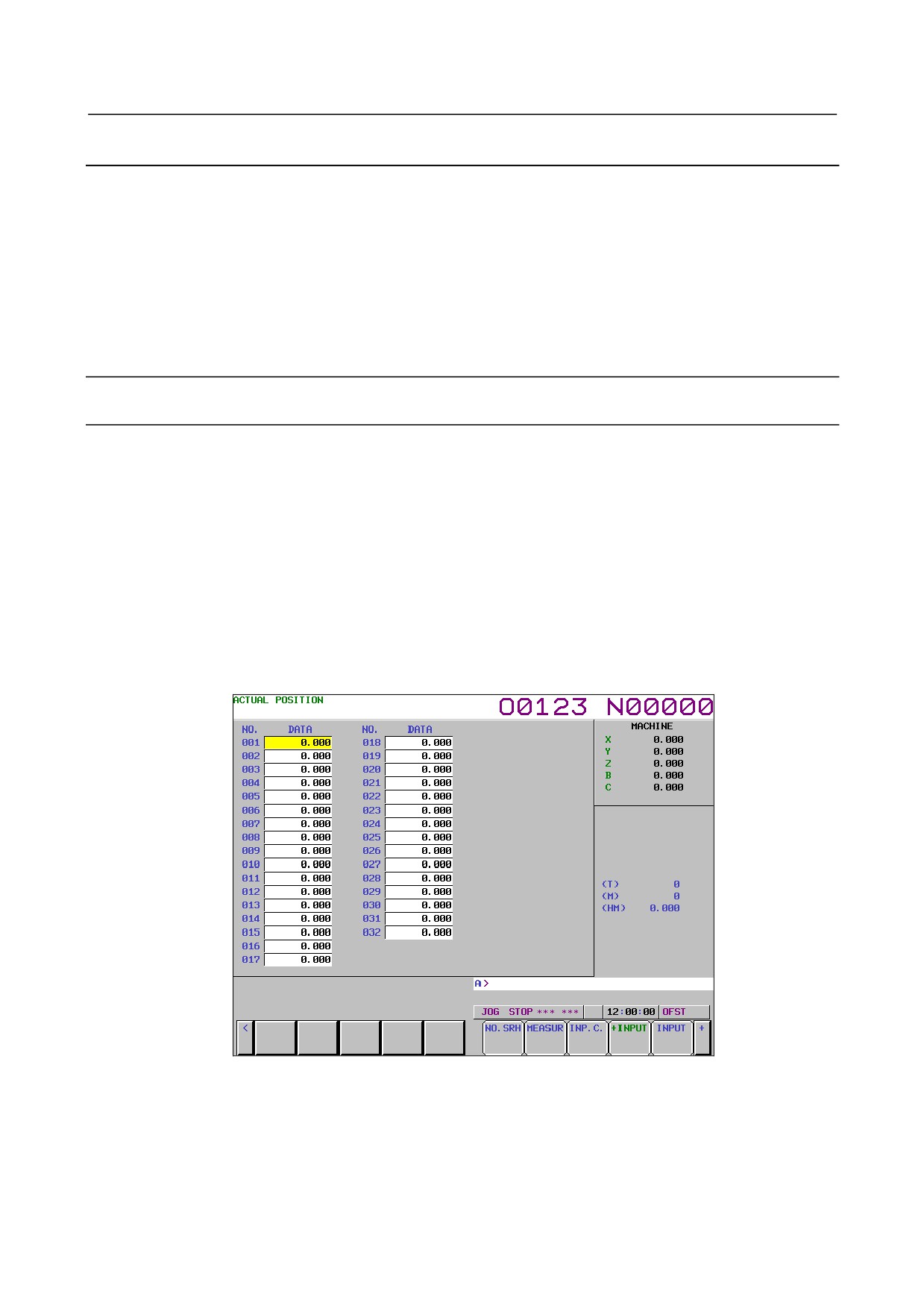
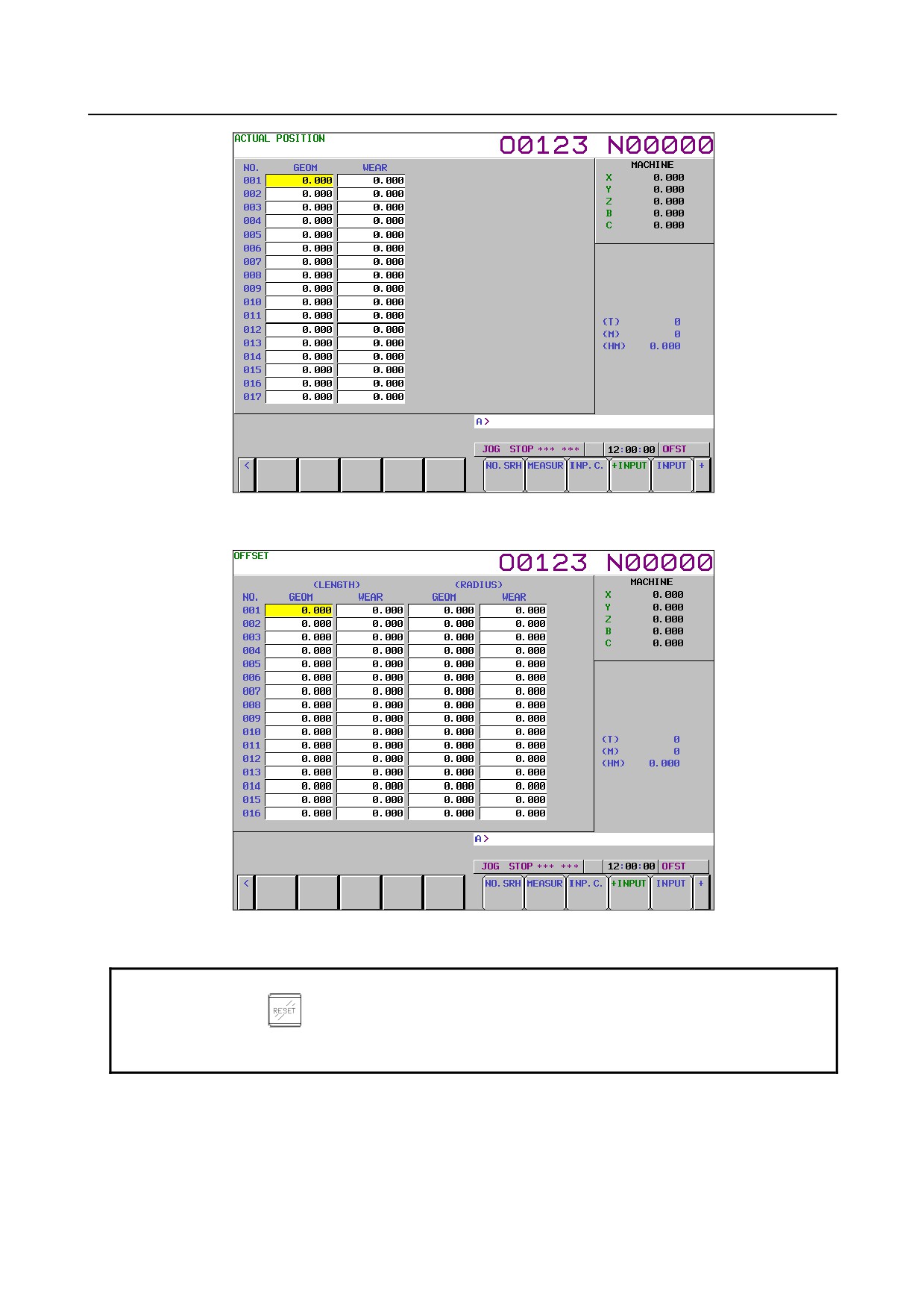
The tool length compensation measurement screen varies slightly depending on whether tool length
compensation memory A, B (geometry compensation and wear compensation are treated differently),
or C
(geometry compensation and wear compensation are treated differently, and cutter
compensation and tool length compensation are treated differently) is used.
Fig. 1.1.3 (a) Tool length compensation measurement screen for tool compensation memory A (10.4-inch
display unit)
- 355 -
1.SETTING AND DISPLAYING DATA OPERATION
B-64484EN-2/02
Fig. 1.1.3 (b) Tool length compensation measurement screen for tool compensation memory B (10.4-inch
display unit)
Fig. 1.1.3 (c) Tool length compensation measurement screen for tool compensation memory C (10.4-inch
display unit)
NOTE
Pressing the
key resets the displayed T and M addresses to 0. Once MEM
or MDI mode has been selected, however, the modal T and M codes are
displayed.
4
Use the numeric keys to enter the distance from the base measurement surface to the measurement
surface, then press soft key [HM INPUT] to set the distance. For details of the measurement surface
and base measurement surface, see Explanations, below.
- 356 -
B-64484EN-2/02
OPERATION
1.SETTING AND DISPLAYING DATA
5
Select the tool for which the tool length compensation value is to be measured.
While "OFST" is blinking at the bottom of the tool length compensation measurement screen, a T
code or M code can be specified in manual handle feed or jog feed mode (manual numeric
command). First, enter Ttttt (where tttt is a T code number), then press the cycle start button on the
machine operator's panel or MDI unit.
The Ttttt command is executed, thus selecting the tool to be measured. Then, usually, enter the M06
command to move the tool to the spindle position. Once the tool for which the tool length
compensation is to be measured has been selected at the spindle position, position the cursor to the
tool offset number with which the tool length compensation for the selected tool is to be stored. The
positioning of the cursor to the offset number is usually done by the operator. Some machines,
however, automatically position the cursor to an appropriate tool offset number upon the completion
of tool selection, if bit 5 (QNI) of parameter No. 5005 is set to 1.
6
Perform manual handle feed or jog feed to move the tool until it touches the measurement surface of
the workpiece or reference block.
7
Press soft key [MEASUR]. The tool length compensation is stored in the tool compensation memory.
If tool compensation memory B or C is being used, the tool length compensation is set as the tool
geometry value, while 0 is set as the tool wear offset. The cursor remains positioned to the set tool
offset number. To automatically advance the cursor to the next tool offset number upon the
completion of the setting an offset, press soft key [MEASUR+], instead of [MEASUR].
8
Once the tool length compensation has been set, the tool is automatically moved to the tool change
position.
9
This completes tool length compensation measurement for a single tool. To measure the tool length
compensations of other tools, repeat steps 5 to 8.
10
Once the tool length compensations of all tools have been measured, set the tool offset measurement
mode switch on the machine operator's panel to OFF. The "OFST" blinking indication is cleared
from the bottom of the screen.
Procedure for measuring the tool length compensation value (for 15/19-inch display
unit)
Procedure
The tool length compensation value can be measured by manually moving the tool until it touches the
workpiece or a reference block. For details of this operation, refer to the manual supplied by the machine
tool builder.
1
Move the tool to the tool change position by means of manual reference position return, for example.
2
Press mode selection switch HANDLE or JOG.
3
Set the tool offset value measurement mode switch on the machine operator's panel to ON. The tool
length compensation measurement screen appears and "OFST" blinks in the status display at the
bottom of the screen.
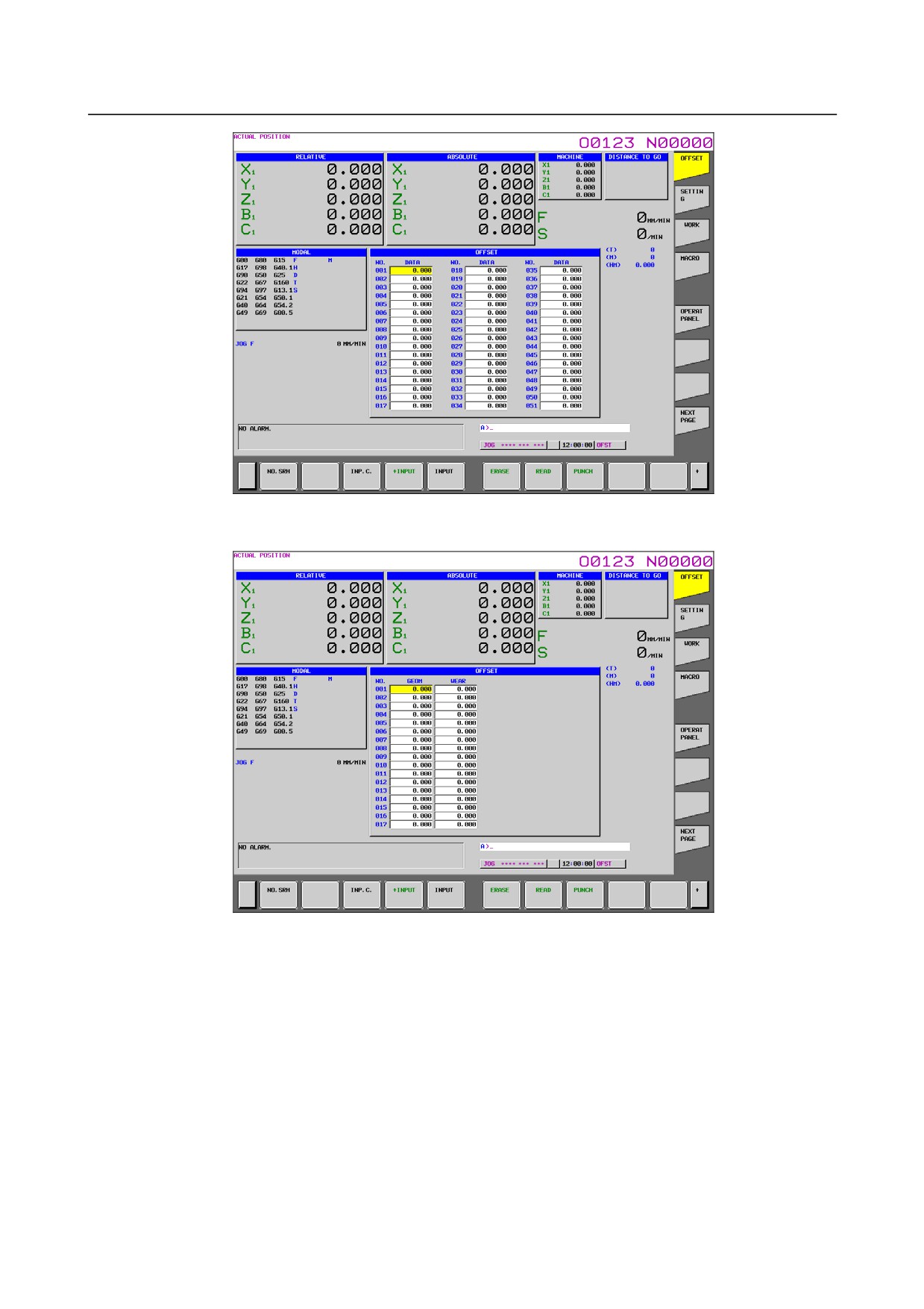
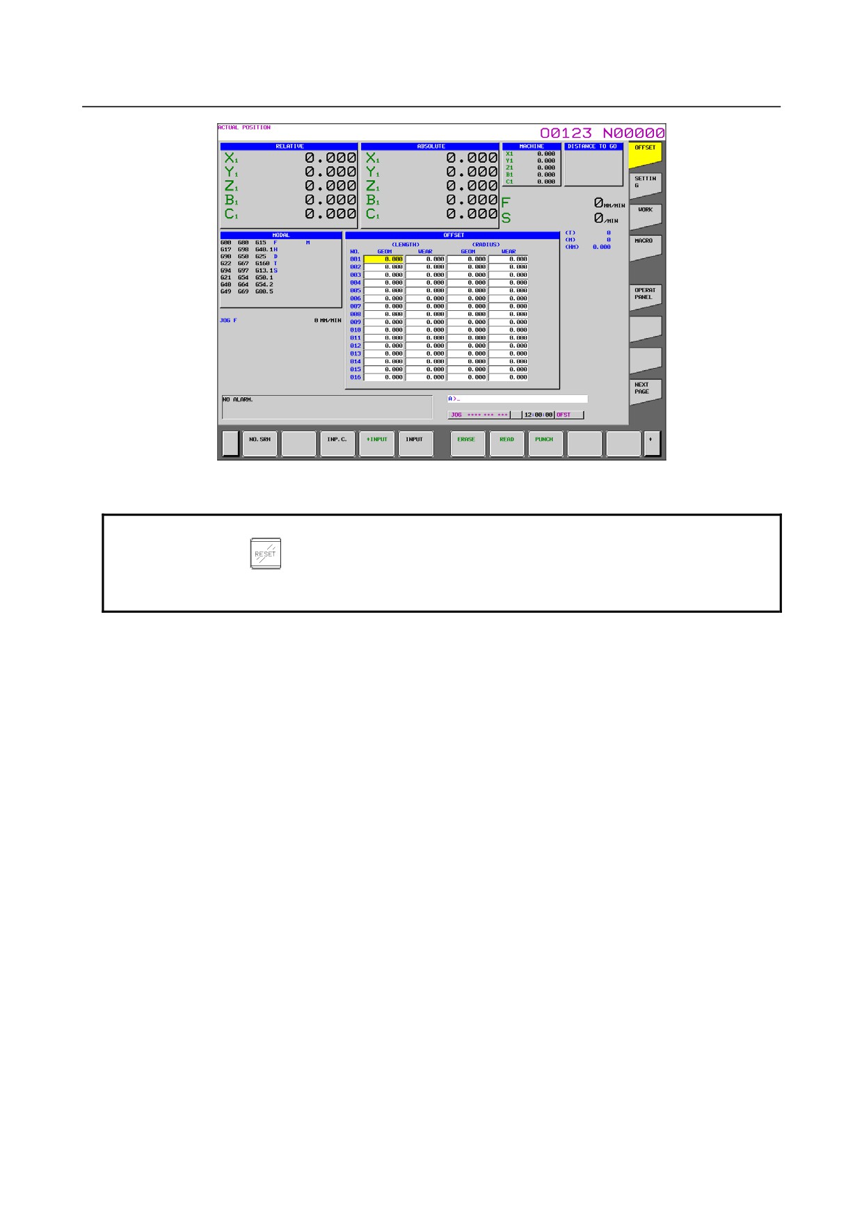
The tool length compensation measurement screen varies slightly depending on whether tool length
compensation memory A, B (geometry compensation and wear compensation are treated differently),
or C
(geometry compensation and wear compensation are treated differently, and cutter
compensation and tool length compensation are treated differently) is used.
- 357 -
1.SETTING AND DISPLAYING DATA OPERATION
B-64484EN-2/02
Fig. 1.1.3 (d) Tool length compensation measurement screen for tool compensation memory A (15-inch
display unit)
Fig. 1.1.3 (e) Tool length compensation measurement screen for tool compensation memory B (15-inch
display unit)
- 358 -
B-64484EN-2/02
OPERATION
1.SETTING AND DISPLAYING DATA
Fig. 1.1.3 (f) Tool length compensation measurement screen for tool compensation memory C (15-inch
display unit)
NOTE
Pressing the
key resets the displayed T and M addresses to 0. Once MEM
or MDI mode has been selected, however, the modal T and M codes are
displayed.
4
Use the numeric keys to enter the distance from the base measurement surface to the measurement
surface, then press horizontal soft key
[HM INPUT] to set the distance. For details of the
measurement surface and base measurement surface, see Explanations, below.
5
Select the tool for which the tool length compensation value is to be measured.
While "OFST" is blinking at the bottom of the tool length compensation measurement screen, a T
code or M code can be specified in manual handle feed or jog feed mode (manual numeric
command). First, enter Ttttt (where tttt is a T code number), then press the cycle start button on the
machine operator's panel or MDI unit. The Ttttt command is executed, thus selecting the tool to be
measured. Then, usually, enter the M06 command to move the tool to the spindle position. Once the
tool for which the tool length compensation is to be measured has been selected at the spindle
position, position the cursor to the tool offset number with which the tool length compensation for
the selected tool is to be stored. The positioning of the cursor to the offset number is usually done by
the operator. Some machines, however, automatically position the cursor to an appropriate tool
offset number upon the completion of tool selection, if bit 5 (QNI) of parameter No. 5005 is set to 1.
6
Perform manual handle feed or jog feed to move the tool until it touches the measurement surface of
the workpiece or reference block.
7
Press horizontal soft key
[MEASUR]. The tool length compensation is stored in the tool
compensation memory. If tool compensation memory B or C is being used, the tool length
compensation is set as the tool geometry value, while 0 is set as the tool wear offset. The cursor
remains positioned to the set tool offset number. To automatically advance the cursor to the next tool
offset number upon the completion of the setting an offset, press horizontal soft key [MEASUR+],
instead of [MEASUR].
8
Once the tool length compensation has been set, the tool is automatically moved to the tool change
position.
9
This completes tool length compensation measurement for a single tool. To measure the tool length
compensations of other tools, repeat steps 5 to 8.
- 359 -
1.SETTING AND DISPLAYING DATA OPERATION
B-64484EN-2/02
10 Once the tool length compensations of all tools have been measured, set the tool offset measurement
mode switch on the machine operator's panel to OFF. The "OFST" blinking indication is cleared
from the bottom of the screen.
Explanation
-
Definition of tool length compensation value
In general, the tool length compensation value can be defined in either of the following two ways. Both
methods are based on the same concept: The difference between the tool nose position of the tool and that
of a reference tool is used as the tool offset.
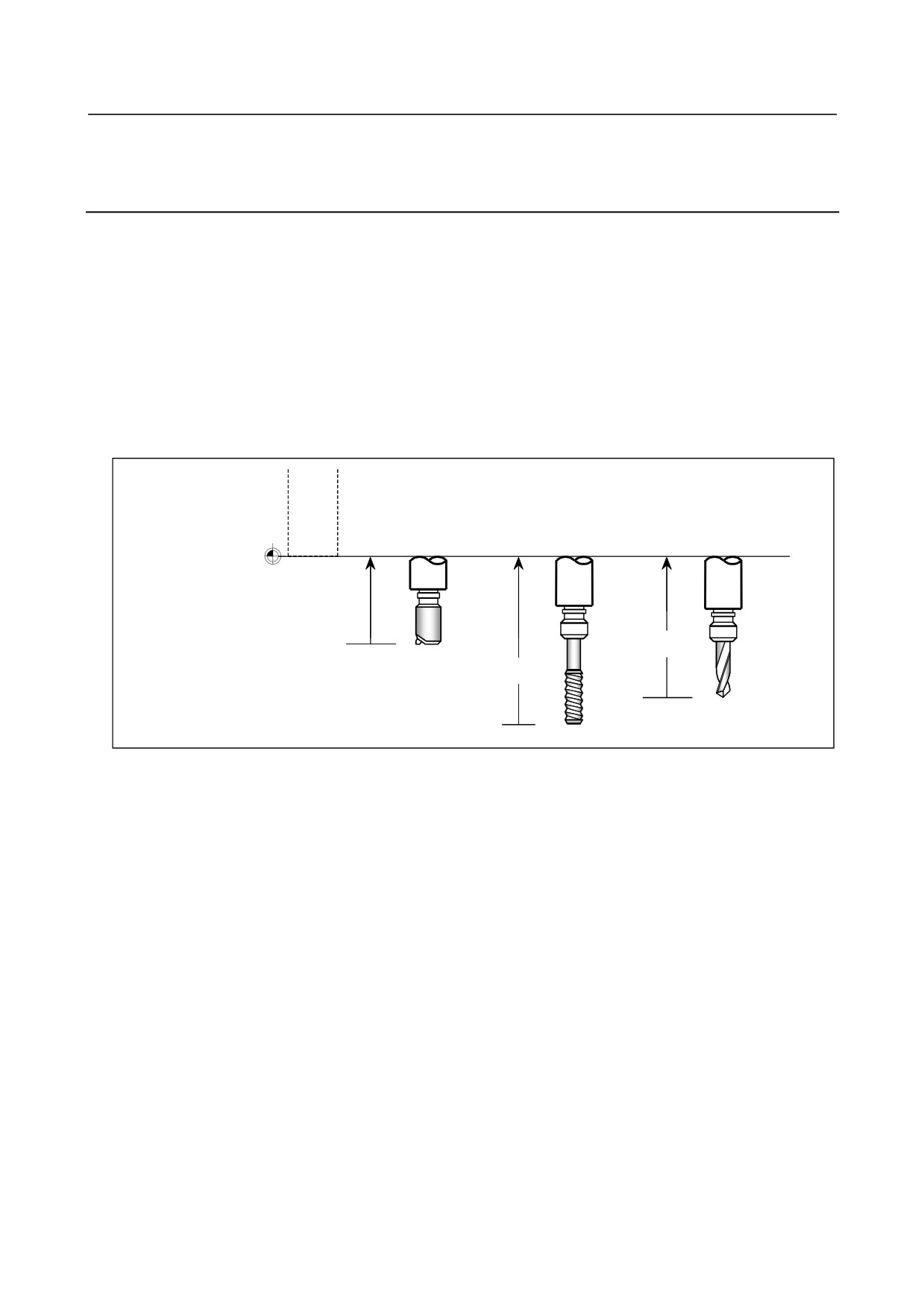
(1) Definition 1
The first method involves using the actual tool length as the tool length compensation. In this case,
the reference tool is an imaginary tool which has its tool nose at the machine zero point when the
machine is positioned to the Z-axis machine zero point. The difference between the tool nose
position of the tool to be measured and that of the reference tool, that is, the distance along the
Z-axis from the machine zero point to the tool nose when the machine is positioned to the Z-axis
machine zero point, is defined as the tool length compensation.
Reference
tool
Machine zero
point
Tool
Tool
Tool
(Reference tool
T01
T02
T03
nose position)
OFSL01
OFSL03
OFSL02
OFSL01 : Tool length compensation for tool T01
OFSL02 : Tool length compensation for tool T02
OFSL03 : Tool length compensation for tool T03
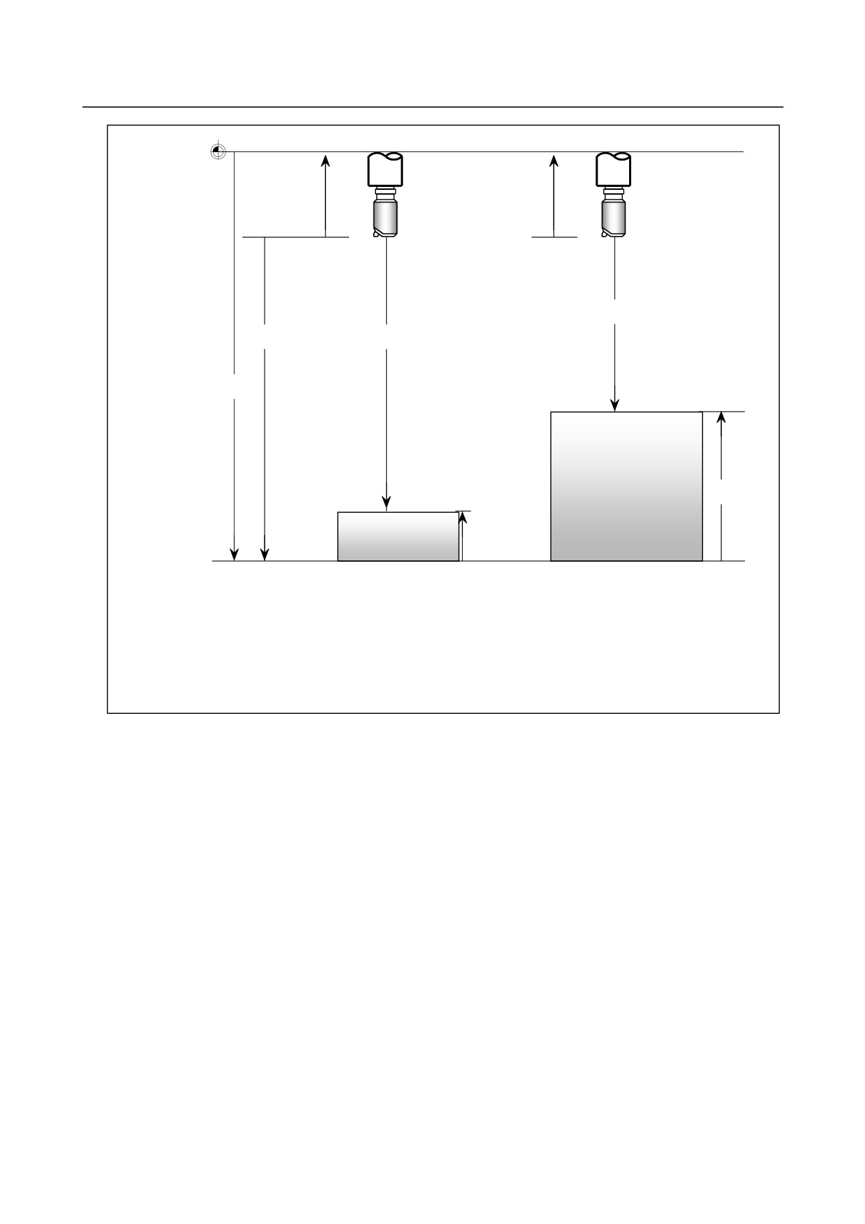
Also, with this function, the tool is manually moved by means of jog feed until its tool nose touches
the top surface of the workpiece or reference block. This surface is called the measurement surface.
Assume that the top surface of the machines table is set as the measurement surface, although this is
actually not allowed because the machine would be damaged. In such a case, distance L from the
machine zero point to the machine table top surface is specific to that machine. Set distance L in a
parameter No. 5022. Assume Zt to be the machine coordinate of the tool at the position where it
would touch the machine table top surface if that surface were set as the measurement surface. The
tool length compensation (OFSL) can then be easily calculated from L and Zt. Because the machine
table top surface cannot actually be used as the measurement surface, however, that surface is
defined as the base measurement surface and the distance from the base measurement surface to the
actual measurement surface, that is, the height of the workpiece or reference block (Hm) must be set.
The tool length compensation value (OFSL) can thus be obtained from the formula shown below.
- 360 -
B-64484EN-2/02
OPERATION
1.SETTING AND DISPLAYING DATA
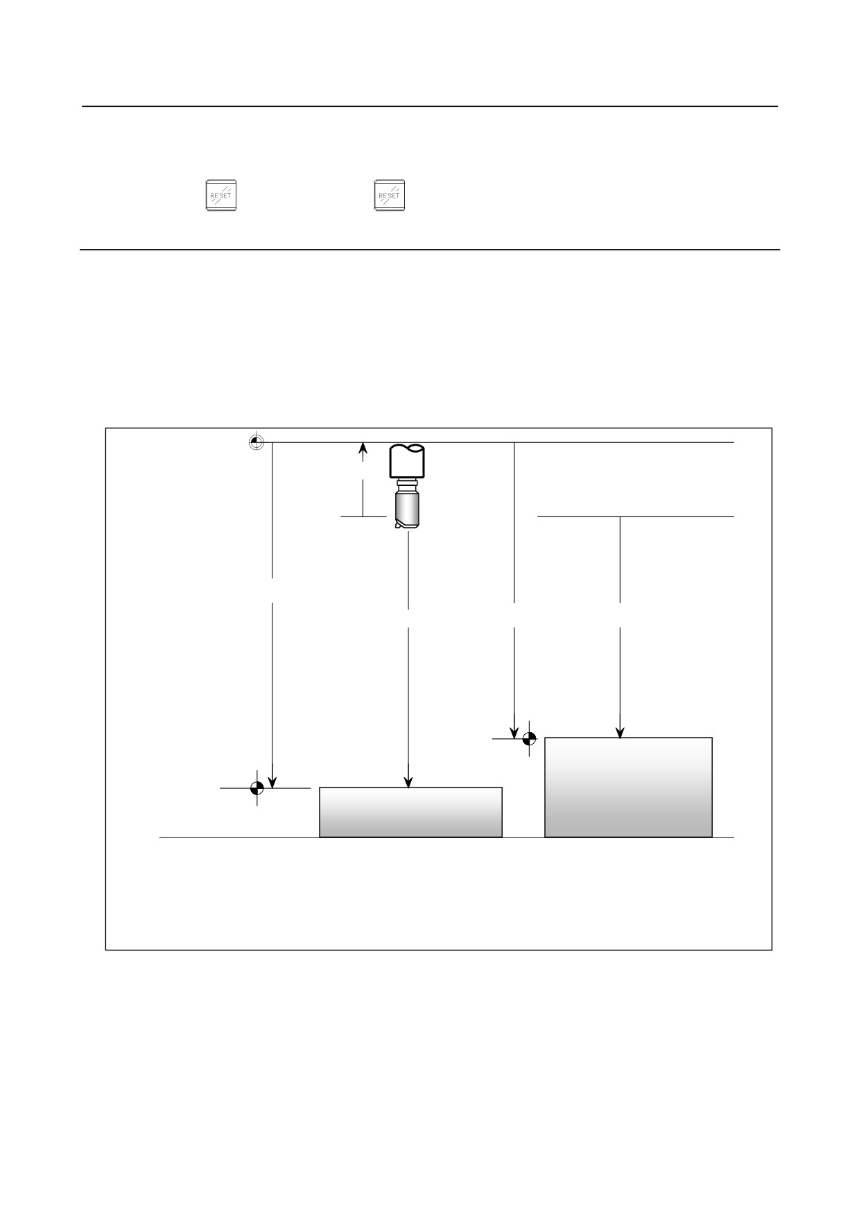
Machine zero
point
Tool
Tool
(Reference tool
OFSL
T01
OFSL
T01
nose position)
Zm
Zt
Zm
L
Measurement surface
Workpiece
Hm
Measurement surface
Reference block
Hm
Base measurement
surface
Machine table
Machine table
L
: Distance from the reference tool nose position to the base measurement surface (machine coordinate of the measurement
surface)
Hm
: Distance from the base measurement surface to the actual measurement surface
Zm
: Distance from the tool nose to be measured to the measurement surface when the tool is positioned to the machine zero point
(Zt
: Distance from the tool nose to be measured to the base measurement surface when the tool is positioned to the machine zero
point)
OFSL: Tool length compensation value (OFSL = Zm - Hm - L)
Defining the actual tool length as the tool length compensation has the advantage of eliminating the
need for remeasuring, even if the workpiece is changed, provided the tool is not worn. Another
advantage is that the tool length compensation need not be re-set when multiple workpieces are
machined. In this case, assign a workpiece coordinate system to each workpiece, using G54 to G59,
and set the workpiece origin offset for each workpiece.
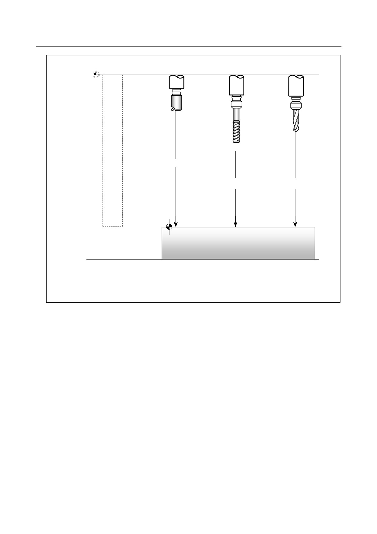
(2) Definition 2
In the second definition method, the tool length compensation is the distance from the tool nose
position to the workpiece coordinate system origin when the machine is positioned to the Z-axis zero
point. A tool length compensation defined in this way will be equal to the difference between the
length of the tool to be measured and that of the reference tool, in the same way as with definition 1.
The reference tool for definition 2 is, however, an imaginary tool which has a tool nose at the
workpiece coordinate system origin when the machine is positioned to the Z-axis zero point.
- 361 -
1.SETTING AND DISPLAYING DATA OPERATION
B-64484EN-2/02
Machine
zero point
Tool
T01
Tool
Tool
T02
T03
OFSL01
OFSL02
OFSL03
Workpiece
Reference coordinate
tool
system origin
Workpiece
OFSL01 : Tool length offset for tool T01
OFSL02 : Tool length offset for tool T02
OFSL03 : Tool length offset for tool T03
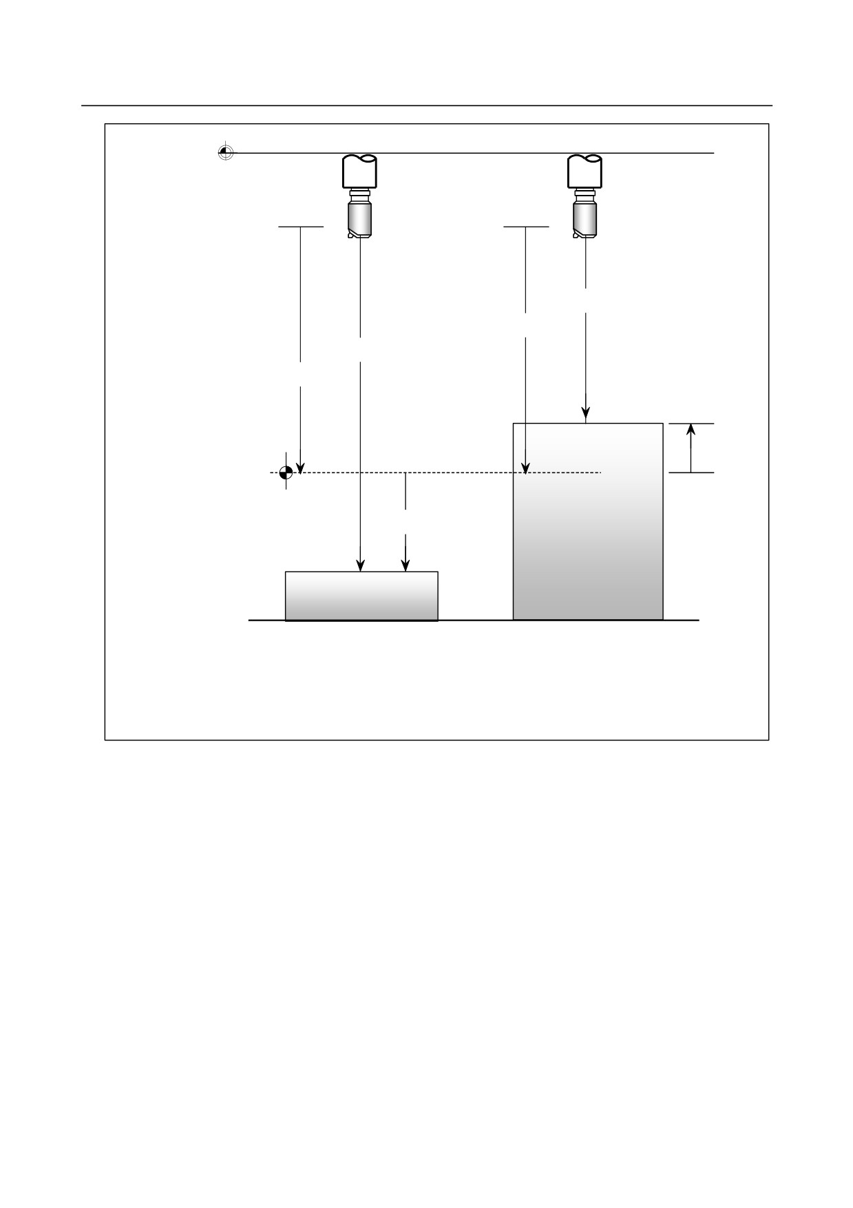
The base measurement surface for this definition is located at the workpiece coordinate system
origin. Because of the reference tool nose is also located at the workpiece coordinate system origin,
distance L from the reference tool nose position to the base measurement surface is 0. Set, therefore,
0 in the parameter for distance L (No. 5022). The actual measurement surface is usually the same as
the base measurement surface, located at the workpiece coordinate system origin. If, however, the
measurement surface is the top surface of the reference block, or if the workpiece coordinate system
origin is located on other than the top surface of the workpiece (for example, when the origin is
shifted from the workpiece top surface by an amount equal to the cutting allowance), set the distance
from the base measurement surface to the actual measurement surface as Hm, such that the tool
length compensation (OFSL) can be calculated using the same formula as that used for definition 1.
- 362 -
B-64484EN-2/02
OPERATION
1.SETTING AND DISPLAYING DATA
Machine
zero point
Tool
Tool
T01
T01
Zm
OFSL
Zm
OFSL
Measurement
surface
Hm
Workpiece coordinate system
origin
(base measurement surface)
Hm
Workpiece
Measurement
surface
Reference block
Machine table
Machine table
L
: Distance from the reference tool tip position to the base measurement surface (= 0)
Hm
: Distance from the base measurement surface to the actual measurement surface
Zm
: Distance from the tip of the tool to be measured to the measurement surface when
the tool is positioned to the machine zero point
OFSL : Tool length offset (OFSL = Zm - Hm - L)
The reference tool for definition 2 has a tool nose at the workpiece coordinate system origin when
the machine is positioned to the Z-axis zero point. Whenever the workpiece is changed, therefore,
the tool length compensation must be remeasured. Remeasuring is not, however, necessary if the
difference between the workpiece coordinate system origin for a new workpiece and that when the
tool length compensation value was measured is set as the new workpiece origin offset (any of G54
to G59). In such a case, the tool length compensation need not be modified, even when the
workpiece is changed.
Taking a different point of view, definition 2 can be thought of as setting the workpiece origin offset
as the tool length compensation for each tool.
-
Measuring the tool length compensation along a specified axis
Because the tool is usually mounted in parallel with the Z-axis, the tool length compensation is measured
by moving the tool along the Z-axis. Some machines, however, have their W-axis in parallel with the
Z-axis, making it necessary to measure the tool length compensation by moving the tool along the W-axis.
Moreover, some machines, when fitted with an attachment, support the mounting of the tool in parallel
with an axis other than the Z-axis. For such a machine, the tool length compensation can be measured
along a specified axis by setting bit 2 (TMA) of parameter No. 5007 to 1.
To measure the tool length compensation along an axis other than the Z-axis, first set distance L from the
reference tool nose position to the base measurement surface, for each of the axes along which the tool
length compensation may be measured, in parameter No. 5022, in addition to distance L along the Z-axis.
- 363 -
1.SETTING AND DISPLAYING DATA OPERATION
B-64484EN-2/02
Next, set distance Hm from the base measurement surface to the actual measurement surface for the axis
along which the tool length compensation is to be measured (see Explanations, below). Finally, move the
tool along that axis until it touches the workpiece or reference block, then enter the name of that axis
before pressing soft key [MEASUR] or [MEASUR+]. When the tool offset is measured along the W-axis,
for example, enter W then press soft key [MEASUR] or [MEASUR+].
-
Tool change position
The tool change position must be set beforehand, using bits 1 (TC3) and 0 (TC2) of parameter No.
5007.
Table 1.1.3 (a)
TC3
TC2
Meaning
0
0
The tool change position is the first reference position (G28)
0
1
The tool change position is the second reference position (G30 P2)
1
0
The tool change position is the third reference position (G30 P3)
1
1
The tool change position is the fourth reference position (G30 P4)
Procedure for measuring the workpiece origin offset (for 8.4/10.4-inch display unit)
In addition to the workpiece origin offset along the tool lengthwise axis, that is, the Z-axis, the workpiece
origin offsets along the X- and Y-axes, on a plane perpendicular to the Z-axis, can also be measured
easily. The workpiece origin offsets along the X- and Y-axes can be measured regardless of whether the
workpiece origin is located on a surface of the workpiece or at the center of a hole to be machined. For
details of this measurement, refer to the manual supplied by the machine tool builder.
-
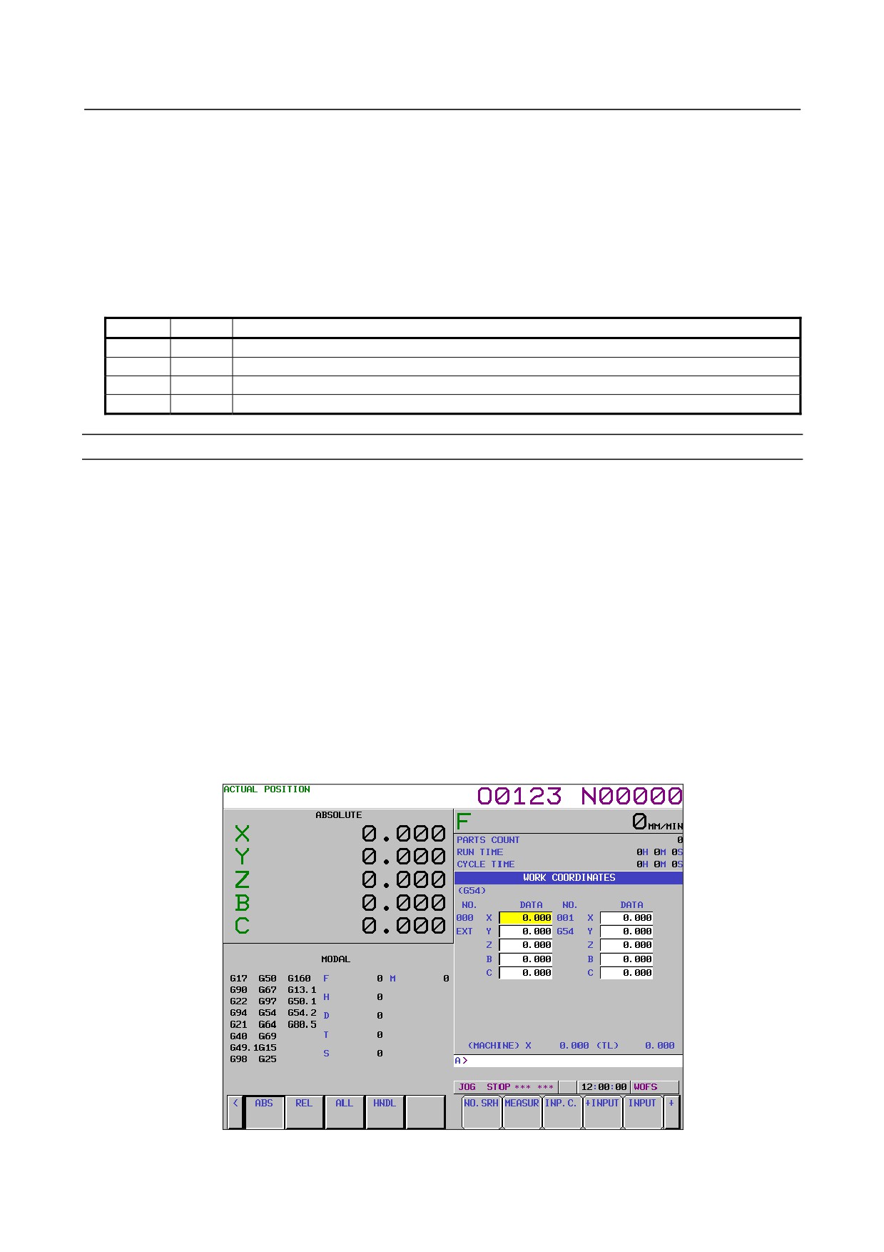
Measuring the Z-axis workpiece origin offset
1
Select a tool using an MDI command, then move it to the spindle position (see the explanation of the
procedure for measuring the tool length compensation). The tool length compensation for the
selected tool must be measured beforehand.
2
Press mode selection switch HANDLE or JOG.
3
Set the workpiece origin offset measurement mode switch on the machine operator's panel to ON.
The workpiece origin offset screen appears and "WOFS" blinks in the status display at the bottom of
the screen.
4
Enter the tool length compensation for the selected tool. Enter the offset using numeric keys then
press soft key [TL-INP].
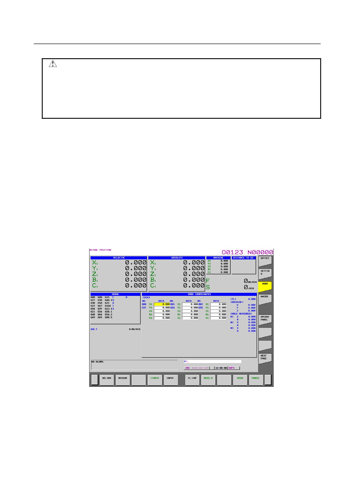
Fig. 1.1.3 (g) Workpiece origin offset setting screen (10.4-inch display unit)
- 364 -
B-64484EN-2/02
OPERATION
1.SETTING AND DISPLAYING DATA
5
Position the cursor to the workpiece origin offset number to be used to store the offset (any of G54
to G59). No problem will arise even if the cursor is positioned to the offset for other than the Z-axis.
6
Move the tool by means of manual handle feed or jog feed until it touches the top surface of the
workpiece.
7
Enter the axis name, Z, press soft key [MEASUR], then press soft key [INPUT]. The Z-axis
workpiece origin offset value is set and the cursor is positioned to the set Z-axis workpiece origin
offset. There is no need to enter Z provided the parameter has been set so that only the Z-axis
workpiece origin offset is to be measured (bit 3 (WMA) of No. 5007 = 0).
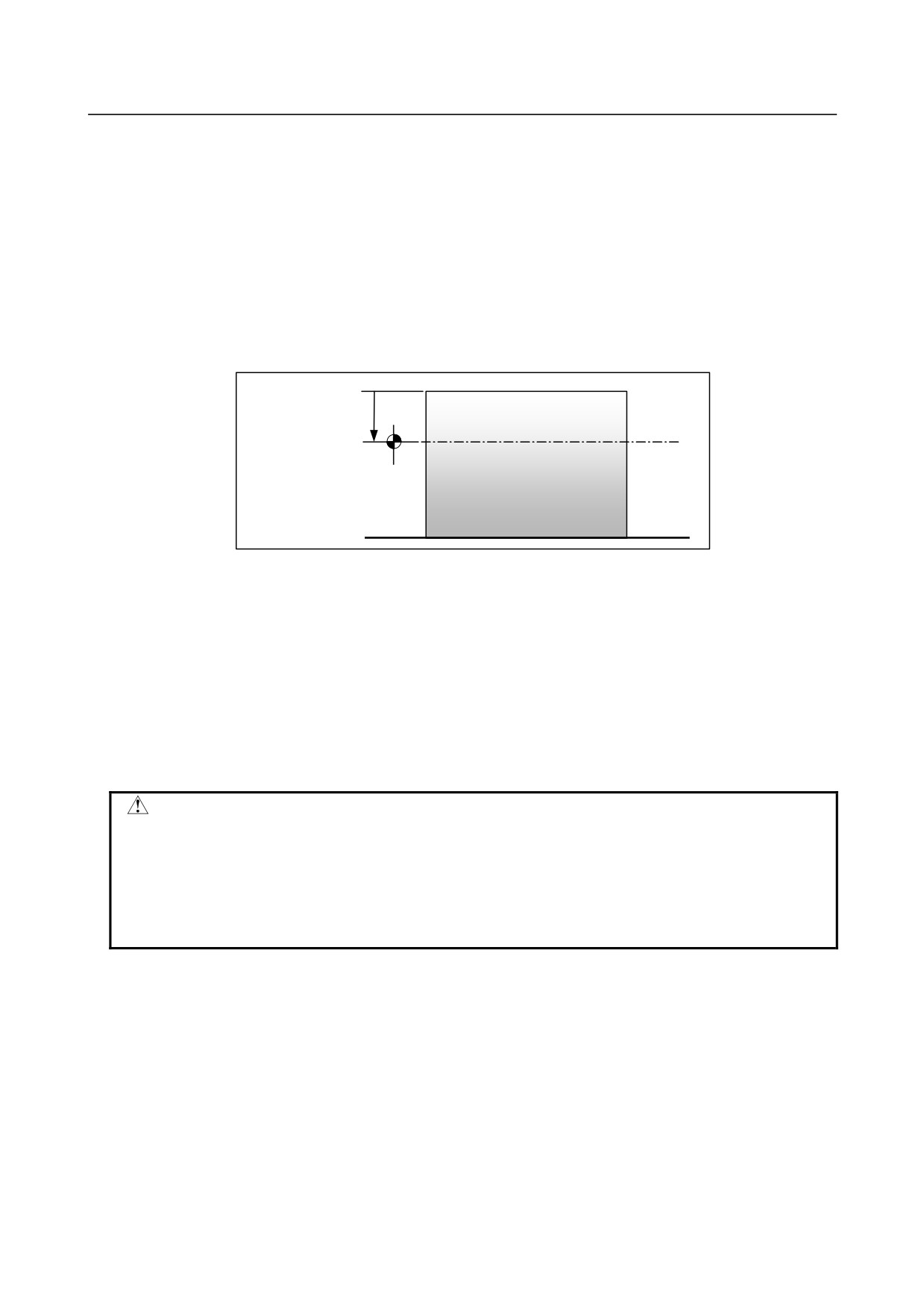
To set the workpiece origin on other than the workpiece top surface (for example, when the origin is
shifted from the workpiece top surface by an amount equal to the cutting allowance), enter the
amount of shift (S in the Fig. 1.1.3 (h)) using the numeric keys, press soft key [MEASUR], then
press soft key [INPUT].
S
Workpiece origin
Workpiece
Fig. 1.1.3 (h)
8
To measure any subsequent workpiece origins, retract the tool from the workpiece, then repeat steps
5 to 7.
-
Measuring the X-/Y-axis workpiece origin offset based on a reference surface
To set the X- or Y-axis workpiece origin offset on a specified surface of the workpiece, set bit 3 (WMA)
of parameter No. 5007 to 1, then follow the same procedure as that for measuring the Z-axis workpiece
origin offset. In step 4, however, enter the cutter compensation value for the selected tool, instead of the
tool length compensation. After entering the cutter compensation value with the numeric keys, press soft
key [TL-INP].
CAUTION
When entering the cutter compensation value, ensure that its sign is entered
correctly.
• When the measurement surface is located in the positive (+) direction relative
to the tool, enter a minus (-) sign.
• When the measurement surface is located in the negative (-) direction relative
to the tool, enter a plus (+) sign.
-
Measuring the X-/Y-axis workpiece origin offset based on a reference hole
1
Connect a measurement probe, fitted with a sensor, to the spindle.
2
Press mode selection switch HANDLE or JOG.
3
Set the workpiece origin offset measurement mode switch on the machine operator's panel to ON.
The workpiece origin offset screen appears and "WOFS" blinks in the status display at the bottom of
the screen, indicating that the preparation required prior to measuring the workpiece origin offset has
been completed.
4
Position the cursor to the workpiece origin offset number to be used to store the offset (any of G54
to G59). No problem will arise even if the cursor is positioned to the offset for other than the X- or
Y-axis.
5
Move the tool by means of manual handle feed or jog feed until the measurement probe touches the
circumference of the hole. Do not move the tool along more than one axis at any one time.
- 365 -
1.SETTING AND DISPLAYING DATA OPERATION
B-64484EN-2/02
6
As soon as the sensor detects contact with the circumference, input a skip signal to the machine, thus
stopping the axial movement of manual handle feed or jog feed. Simultaneously, the position at
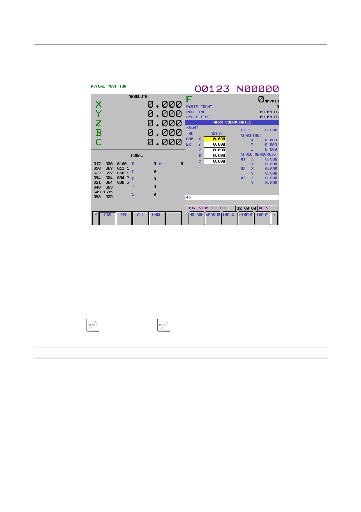
which feed stopped is stored as the first measurement point. The machine coordinates of the stored
measurement point are displayed at the bottom right of the screen, as Fig. 1.1.3 (i):
Fig. 1.1.3 (i) Workpiece origin offset setting screen (10.4-inch display unit)
7
Move the measurement probe to the second measurement point. At this time, the CNC interlocks the
machine to prevent the probe from moving in the direction in which it was moved so as to touch the
current measurement point. For example, when the probe touched the measurement point after being
moved in the +X direction, movement of the probe to the next measurement point is allowed only in
the -X direction. Movement in the +X, +Y, or -Y direction is interlocked until the skip signal is set
to 0. Once the probe touches the second measurement point, follow the same procedure as that for
storing the first measurement point.
8
Once the probe has touched the third measurement point, press soft key
[MEASUR], then
[CENTER]. This calculates the center of the hole from the coordinates of the three measured points,
then sets the X- and Y-axis workpiece origin offsets. To cancel and restart measurement at any point,
press the
key. Pressing the
key clears the coordinates of all stored measurement
points.
Procedure for measuring the workpiece origin offset (for 15/19-inch display unit)
In addition to the workpiece origin offset along the tool lengthwise axis, that is, the Z-axis, the workpiece
origin offsets along the X- and Y-axes, on a plane perpendicular to the Z-axis, can also be measured
easily. The workpiece origin offsets along the X- and Y-axes can be measured regardless of whether the
workpiece origin is located on a surface of the workpiece or at the center of a hole to be machined. For
details of this measurement, refer to the manual supplied by the machine tool builder.
-
Measuring the Z-axis workpiece origin offset
1
Select a tool using an MDI command, then move it to the spindle position (see the explanation of the
procedure for measuring the tool length compensation). The tool length compensation for the
selected tool must be measured beforehand.
2
Press mode selection switch HANDLE or JOG.
3
Set the workpiece origin offset measurement mode switch on the machine operator's panel to ON.
The workpiece origin offset screen appears and "WOFS" blinks in the status display at the bottom of
the screen.
- 366 -
B-64484EN-2/02
OPERATION
1.SETTING AND DISPLAYING DATA
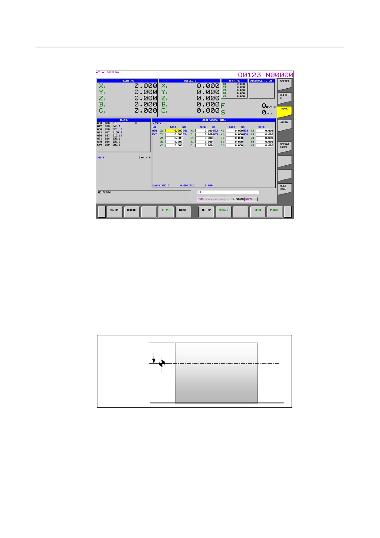
4
Enter the tool length compensation for the selected tool. Enter the offset using numeric keys then
press horizontal soft key [TL-INP].
Fig. 1.1.3 (j) Workpiece origin offset setting screen (15-inch display unit)
5
Position the cursor to the workpiece origin offset number to be used to store the offset (any of G54
to G59). No problem will arise even if the cursor is positioned to the offset for other than the Z-axis.
6
Move the tool by means of manual handle feed or jog feed until it touches the top surface of the
workpiece.
7
Enter the axis name, Z, press horizontal soft key [MEASUR], then press horizontal soft key
[INPUT]. The Z-axis workpiece origin offset value is set and the cursor is positioned to the set
Z-axis workpiece origin offset. There is no need to enter Z provided the parameter has been set so
that only the Z-axis workpiece origin offset is to be measured (bit 3 (WMA) of No. 5007 = 0).
To set the workpiece origin on other than the workpiece top surface (for example, when the origin is
shifted from the workpiece top surface by an amount equal to the cutting allowance), enter the
amount of shift
(S in the Fig.
1.1.3
(k)) using the numeric keys, press horizontal soft key
[MEASUR], then press horizontal soft key [INPUT].
S
Workpiece origin
Workpiece
Fig. 1.1.3 (k)
8
To measure any subsequent workpiece origins, retract the tool from the workpiece, then repeat steps
5 to 7.
-
Measuring the X-/Y-axis workpiece origin offset based on a reference surface
To set the X- or Y-axis workpiece origin offset on a specified surface of the workpiece, set bit 3 (WMA)
of parameter No. 5007 to 1, then follow the same procedure as that for measuring the Z-axis workpiece
origin offset. In step 4, however, enter the cutter compensation value for the selected tool, instead of the
tool length compensation. After entering the cutter compensation value with the numeric keys, press soft
key [TL INPUT].
- 367 -
1.SETTING AND DISPLAYING DATA OPERATION
B-64484EN-2/02
CAUTION
When entering the cutter compensation value, ensure that its sign is entered
correctly.
• When the measurement surface is located in the positive (+) direction relative
to the tool, enter a minus (-) sign.
• When the measurement surface is located in the negative (-) direction relative
to the tool, enter a plus (+) sign.
-
Measuring the X-/Y-axis workpiece origin offset based on a reference hole
1
Connect a measurement probe, fitted with a sensor, to the spindle.
2
Press mode selection switch HANDLE or JOG.
3
Set the workpiece origin offset measurement mode switch on the machine operator's panel to ON.
The workpiece origin offset screen appears and "WOFS" blinks in the status display at the bottom of
the screen, indicating that the preparation required prior to measuring the workpiece origin offset has
been completed.
4
Position the cursor to the workpiece origin offset number to be used to store the offset (any of G54
to G59). No problem will arise even if the cursor is positioned to the offset for other than the X- or
Y-axis.
5
Move the tool by means of manual handle feed or jog feed until the measurement probe touches the
circumference of the hole. Do not move the tool along more than one axis at any one time.
6
As soon as the sensor detects contact with the circumference, input a skip signal to the machine, thus
stopping the axial movement of manual handle feed or jog feed. Simultaneously, the position at
which feed stopped is stored as the first measurement point. The machine coordinates of the stored
measurement point are displayed at the bottom right of the screen, as Fig. 1.1.3 (l):
Fig. 1.1.3 (l) Workpiece origin offset setting screen (15-inch display unit)
7
Move the measurement probe to the second measurement point. At this time, the CNC interlocks the
machine to prevent the probe from moving in the direction in which it was moved so as to touch the
current measurement point. For example, when the probe touched the measurement point after being
moved in the +X direction, movement of the probe to the next measurement point is allowed only in
the -X direction. Movement in the +X, +Y, or -Y direction is interlocked until the skip signal is set
to 0. Once the probe touches the second measurement point, follow the same procedure as that for
storing the first measurement point.
- 368 -
B-64484EN-2/02
OPERATION
1.SETTING AND DISPLAYING DATA
8
Once the probe has touched the third measurement point, press horizontal soft key [MEASUR], then
[CENTER]. This calculates the center of the hole from the coordinates of the three measured points,
then sets the X- and Y-axis workpiece origin offsets. To cancel and restart measurement at any point,
press the
key. Pressing the
key clears the coordinates of all stored measurement
points.
Explanation
-
Z-axis workpiece origin offset
Definitions 1 and 2, described in "Definition of tool length compensation" in Explanations for measuring
the tool length compensation, also apply to the general concept of the Z-axis workpiece origin offset, as
follows:
(1) Definition 1
In definition 1, the Z-axis workpiece origin offset is defined as the distance from the machine zero
point to the origin of the workpiece coordinate system (Fig. 1.1.3 (m)).
Machine zero
i t
Tool
OFSL
OFSWG54
ZmG54
OFSWG55
ZmG55
Workpiece origin
(G55)
Workpiece origin
Workpiece (G55)
(G54)
Workpiece (G54)
OFSL
: Tool length compensation for the tool used to measure the workpiece origin offset
ZmG54
: Amount of movement from the machine zero point to the origin of the G54 workpiece
when measured with a tool having a length of OFSL
ZmG55
: Amount of movement from the machine zero point to the origin of the G55 workpiece
when measured with a tool having a length of OFSL
OFSWG54 : Workpiece origin offset for the G54 workpiece
OFSWG55 : Workpiece origin offset for the G55 workpiece
Fig. 1.1.3 (m)
As can be seen from the Fig. 1.1.3 (m), the Z-axis workpiece origin offset can be calculated from the
following formula:
OFSW=Zm-OFSL
where
OFSW
:
Workpiece origin offset
OFSL
:
Tool length compensation for the tool used to measure the workpiece origin offset
Zm
:
Amount of movement from the machine zero point to the workpiece origin when
measured with a tool having a length of OFSL
- 369 -
1.SETTING AND DISPLAYING DATA OPERATION
B-64484EN-2/02
(2) Definition 2
The tool length compensation in definition 2 equals the Z-axis workpiece origin offset, as described
above. Usually in this case, therefore, the workpiece origin offset need not be set. If, however, the
workpiece is changed after its tool length compensation has been measured, or if multiple
workpieces are machined, the workpiece origin coordinates can be set as follows when assigning
workpiece coordinate systems to G54 to G59, thus eliminating the need to remeasure the tool length
compensation.
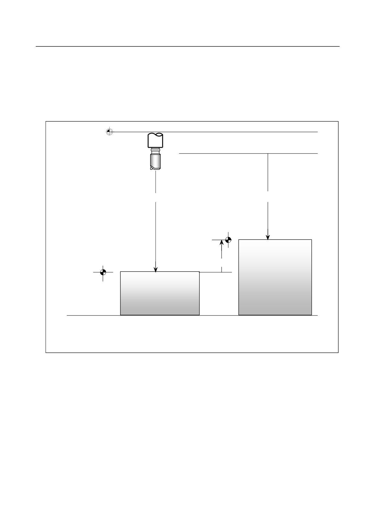
Machine
zero point
Tool
OFSL
ZmG55
Workpiece origin
(G55)
OFSWG55
Workpiece origin
Workpiece (G55)
(G54)
Workpiece (G54)
OFSL
: Tool length compensation measured for the G54 workpiece
ZmG55
: Amount of movement from the machine zero point to the origin of the G55 workpiece when measured with a
tool having a length of OFSL
OFSWG55
: Workpiece origin offset for the G55 workpiece (The workpiece origin offset for the G54 workpiece is 0.)
Fig. 1.1.3 (n)
For definition 2, the workpiece origin offset can be calculated using the same formula as that used
for definition 1:
OFSW = Zm - OFSL
where
OFSW : Workpiece origin offset
OFSL : Tool length compensation for the tool used to measure the workpiece origin offset
Zm
: Amount of movement from the machine zero point to the workpiece origin when measured
with a tool having a length of OFSL
-
X-/Y-axis workpiece origin offset
The X- and Y-axis workpiece origin offsets can be measured regardless of whether the workpiece origin
is located on a surface of the workpiece or at the center of a hole to be machined.
- 370 -
B-64484EN-2/02
OPERATION
1.SETTING AND DISPLAYING DATA
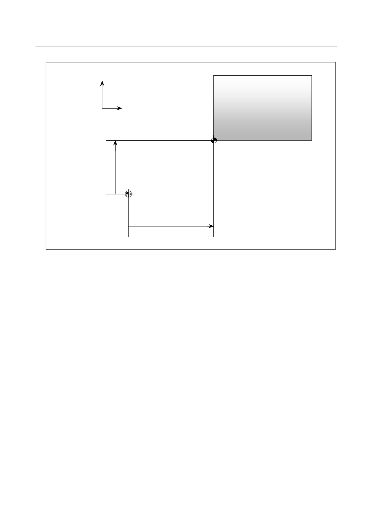
(1) When the workpiece origin is located on a surface
+Y
+X
Workpiece
Workpiece origin
Y-axis workpiece
origin offset
Machine zero point
X-axis workpiece origin offset
Fig. 1.1.3 (o)
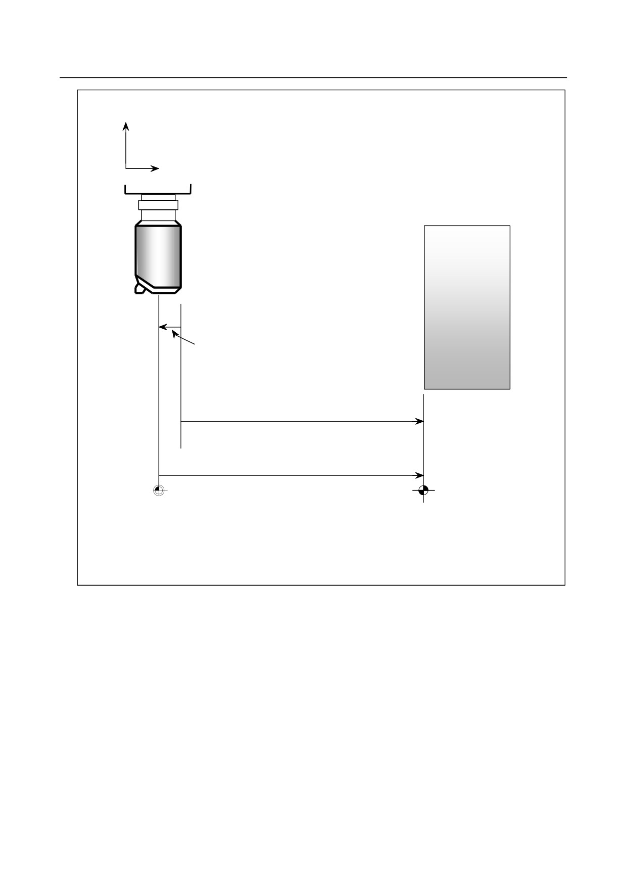
In the case of the Fig. 1.1.3 (o), the workpiece origin is located on a side surface of the workpiece.
The measurement of the X-/Y-axis workpiece origin offset when the origin is located on a surface of
the workpiece is the same as that for the Z-axis workpiece origin offset, but with the following
exception: The tool length compensation for the tool used to measure the offset is used to calculate
the Z-axis workpiece origin offset, while the cutter compensation value for the tool is used to
calculate the X-/Y-axis workpiece origin offset.
- 371 -
1.SETTING AND DISPLAYING DATA OPERATION
B-64484EN-2/02
+Z
+X
Tool
Workpiece
OFSR
Xm
OFSW
Machine zero point
Workpiece origin
OFSR : Cutter compensation value for the tool used to measure the workpiece origin offset
Xm
: Amount of movement from the machine zero point to the workpiece origin when measured with a tool
having a length of OFSR
OFSW : Workpiece origin offset
Fig. 1.1.3 (p)
As can be seen from the Fig. 1.1.3 (p), the workpiece origin offset can be calculated from the
following formula:
OFSW = Xm - OFSR
Pay particularly careful attention, however, to the sign of the cutter compensation value OFSR:
The sign of OFSR is - when the measurement surface is located in the positive (+) direction relative
to the tool center.
The sign of OFSR is + when the measurement surface is located in the negative (-) direction relative
to the tool center.
- 372 -
B-64484EN-2/02
OPERATION
1.SETTING AND DISPLAYING DATA
(2) When the workpiece origin is located at the center of a hole.
+Y
+X
Y-axis workpiece
origin offset
Workpiece
origin
Machine zero point
X-axis workpiece origin offset
Fig. 1.1.3 (q)
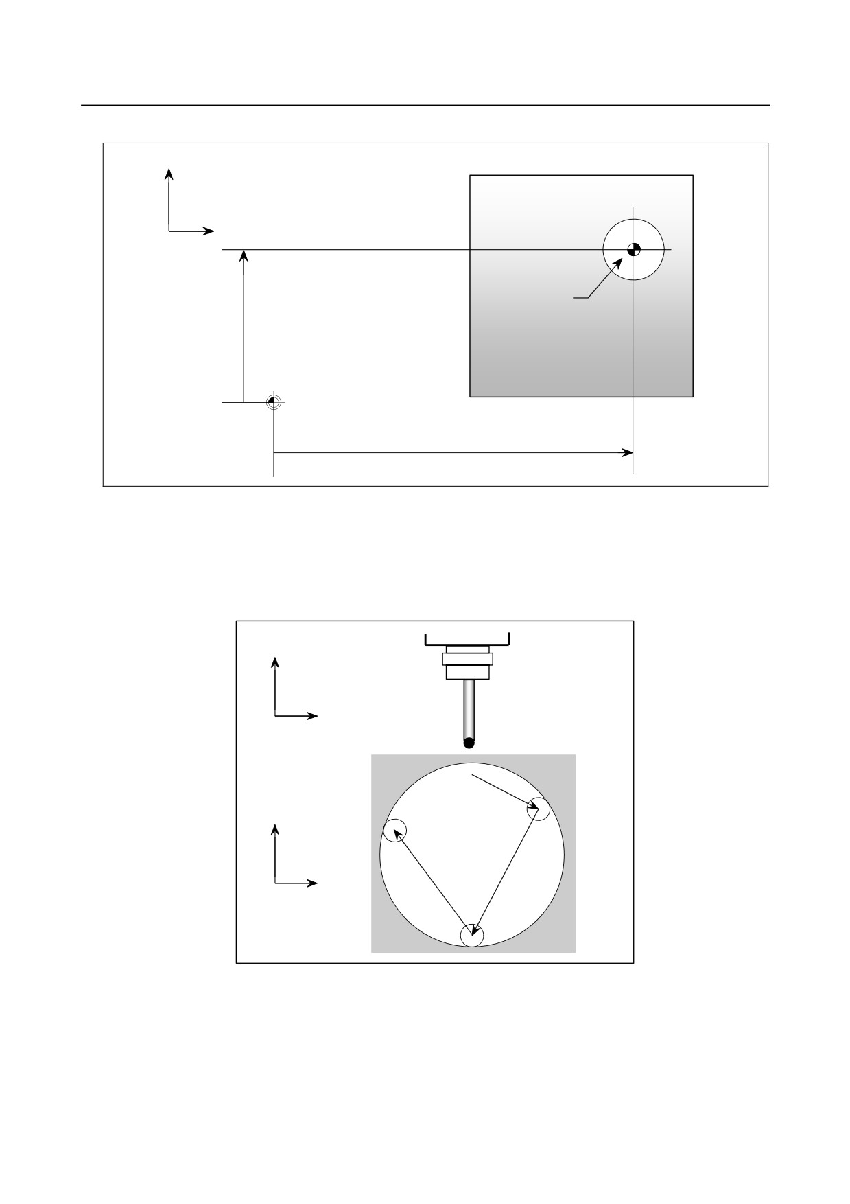
In the case of the Fig. 1.1.3 (q), the workpiece origin is located at the center of a hole in the
workpiece. A measurement probe having a sensor at its tool nose is used to measure the positions of
three arbitrary points on the circumference of the hole. The three points prescribe a unique circle, the
center of which is set as the X-/Y-axis workpiece origin. Set bit 4 (WMH) of parameter No. 5007 to
1 before starting the measurement.
+Z
Measurement probe
having a sensor
+X
+Y
+X
-
Using a skip signal
A measurement probe, fitted with a sensor, can also be used to measure the Z-axis workpiece origin offset
or measure the X-/Y-axis workpiece origin offset based on a surface, in the same way as when measuring
the X-/Y-axis workpiece origin offset based on a hole. By inputting a skip signal as soon as the probe
touches the workpiece surface, feed is automatically stopped. Subsequently, apply the same procedure as
that for each measurement.
- 373 -
1.SETTING AND DISPLAYING DATA OPERATION
B-64484EN-2/02
1.1.4
Setting and Displaying the Rotary Table Dynamic Fixture
Offset
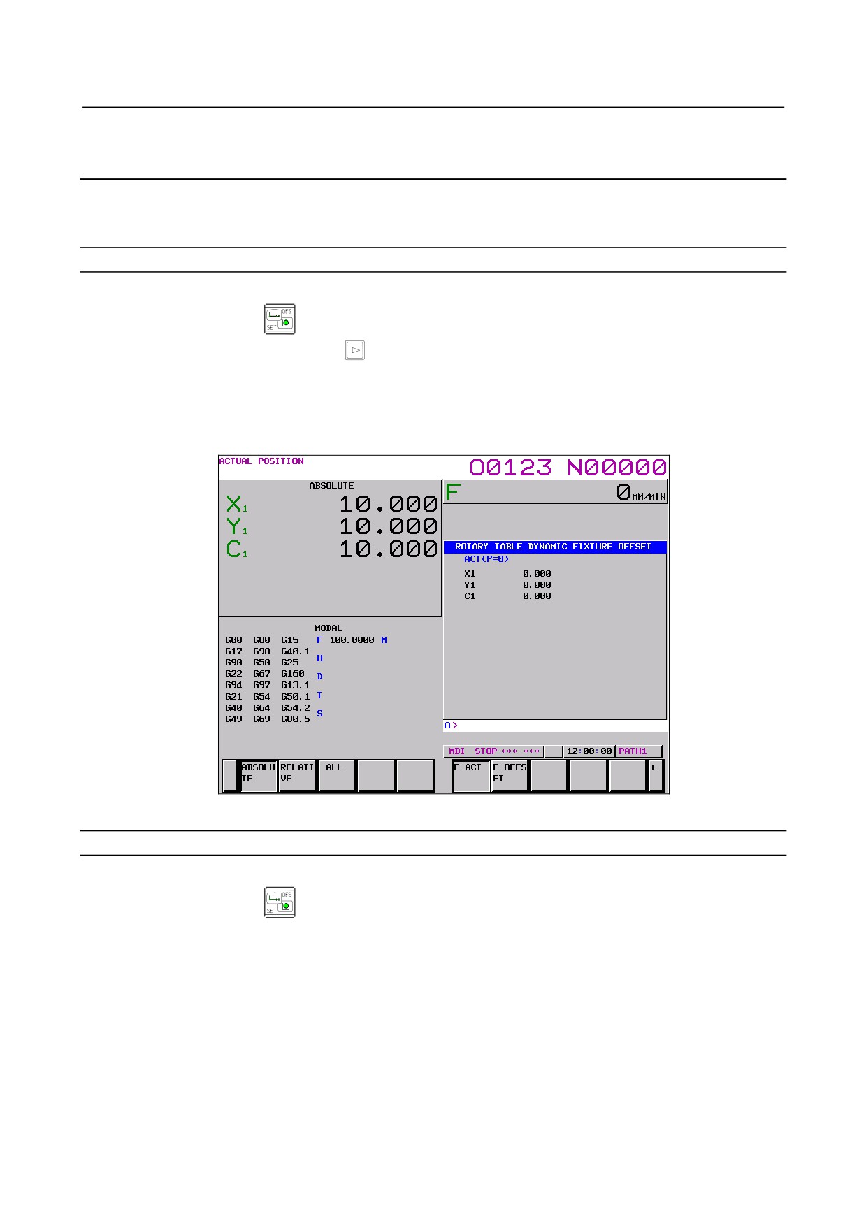
The fixture offset screen is either a fixture offset (ACT) screen for verifying the currently selected fixture
offset value or a fixture offset screen for setting and verifying eight fixture offset value sets.
Active Fixture offset screen (for 8.4/10.4-inch display unit)
Procedure
1
Press function key
2
Press the continuous menu key
several times, until soft key [F-ACT] appears.
3
Press soft key [F-ACT].
The fixture offset (ACT) screen displays.
This screen displays the currently selected fixture offset number (P) and fixture offset vector.
Fig. 1.1.4 (a) Active fixture offset display screen (10.4-inch display unit)
Active Fixture offset screen (for 15/19-inch display unit)
Procedure
1
Press function key
2
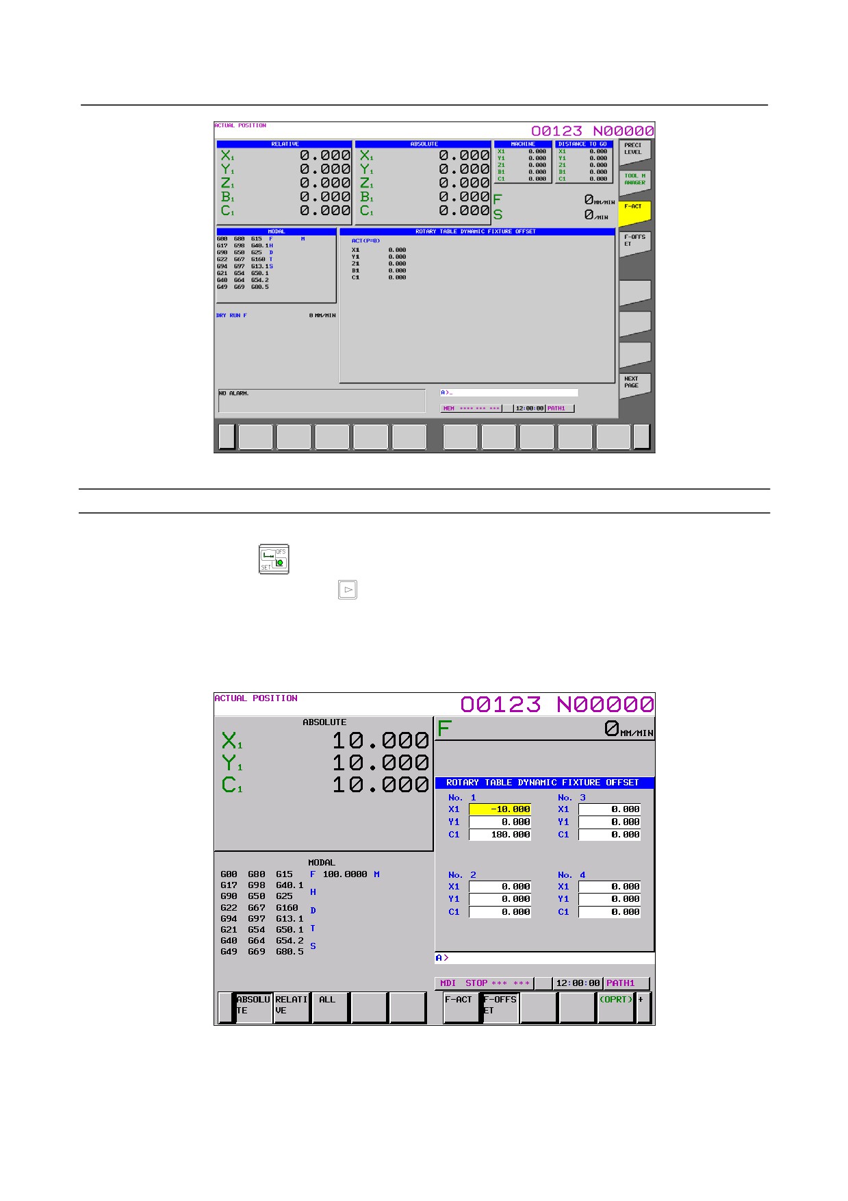
Press vertical soft key [NEXT PAGE] until vertical soft key [F-ACT] appears.
3
Press vertical soft key [F-ACT].
The fixture offset (ACT) screen displays.
This screen displays the currently selected fixture offset number (P) and fixture offset vector.
- 374 -
B-64484EN-2/02
OPERATION
1.SETTING AND DISPLAYING DATA
Fig. 1.1.4 (b) Active fixture offset display screen (15-inch display unit)
Fixture offset setting screen (for 8.4/10.4-inch display unit)
Procedure
1
Press function key
2
Press the continuous menu key
several times, until soft key [F-OFFSET] appears.
3
Press soft key [F-OFFSET] .
The fixture offset (ACT) screen displays.
The number of groups that are displayed on one screen is fixed 1 to 4 groups by number of control axis.
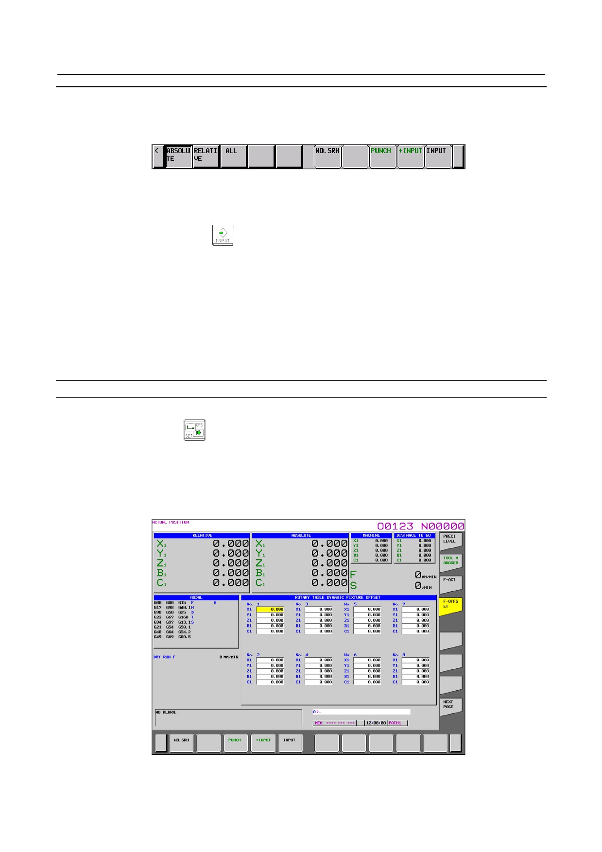
Fig. 1.1.4 (c) Fixture offset setting screen (10.4-inch display unit)
- 375 -
1.SETTING AND DISPLAYING DATA OPERATION
B-64484EN-2/02
Operation
-
Entering numeric values
• Pres soft key [(OPRT)] to display the following operation soft key.
• Use the page and cursor keys, and soft key [NO.SRH] to place cursor at a desired items to be set.
• Enter data, then press soft key [INPUT]
• To add a value to already set data, press soft key [+INPUT].
Data can be set using the
MDI key.
-
Number of groups of fixture offset values
NO. 01 to NO. 08 indicates the number of a group of fixture offset values.
There are eight groups. Soft key [NO. SRH] can be used to search for a desired group number.
-
Inputting fixture offset values
Soft key [F INPUT] can be used to output fixture offset values from an external device.
-
Outputting fixture offset values
Soft key [F OUTPUT] can be used to output fixture offset values to an external device.
Fixture offset setting screen (for 15/19-inch display unit)
Procedure
1
Press function key
2
Press vertical soft key [NEXT PAGE] until vertical soft key [F-OFFSET] appears.
3
Press vertical soft key [F-OFFSET] .
The fixture offset (ACT) screen displays.
The number of groups that are displayed on one screen is fixed 1 to 8 groups by number of control axis.
Fig. 1.1.4 (d) Fixture offset setting screen (15-inch display unit)
- 376 -
B-64484EN-2/02
OPERATION
1.SETTING AND DISPLAYING DATA
Operation
-
Entering numeric values
• Use the page and cursor keys, and horizontal soft key [NO.SRH] to place cursor at a desired items to
be set.
• Enter data, then press horizontal soft key [INPUT]
• To add a value to already set data, press horizontal soft key [+INPUT].
Data can be set using the
MDI key.
-
Number of groups of fixture offset values
NO. 01 to NO. 08 indicates the number of a group of fixture offset values.
There are eight groups. Horizontal soft key [NO. SRH] can be used to search for a desired group number.
-
Inputting fixture offset values
Horizontal soft key [F INPUT] can be used to output fixture offset values from an external device.
-
Outputting fixture offset values
Soft key [F OUTPUT] can be used to output fixture offset values to an external device.
1.1.5
Input of Tool Offset Value Measured B
Explanation
-
Basic procedure for setting the tool offset value
Shown below is the basic procedure for setting the tool offset value:
(1) Execute manual reference position return.
(2) Select manual handle mode or manual continuous feed mode and set the tool compensation value
write mode select signal GQSMC to 1.
(3) Select a tool to be measured.
(4) Use tool offset number select signal OFNC0 to OFNC9 to select the tool offset number to be set.
(5) Near the tool to the touch sensor by manual operation.
(6) When the tool nose touches the contact surface of the touch sensor and the tool offset value write
signal +MIT1 is output, the following operations are performed:
i)
The tool is subject to axis interlock in the axis direction in which the tool is moving and
automatically stops manual operation.
ii)
The calculated tool offset value is set with the tool offset number set by tool offset number
select signal OFNC0 to OFNC9.
(7) For both X-axis and Z-axis, their offset values are set by operations (5) and (6).
(8) Repeat operations (3) to (7) for all necessary tools.
(9) Set the tool compensation value writing mode signal GQSMC to 0.
1.1.6
Spindle Unit Compensation, Nutating Rotary Head Tool
Length Compensation
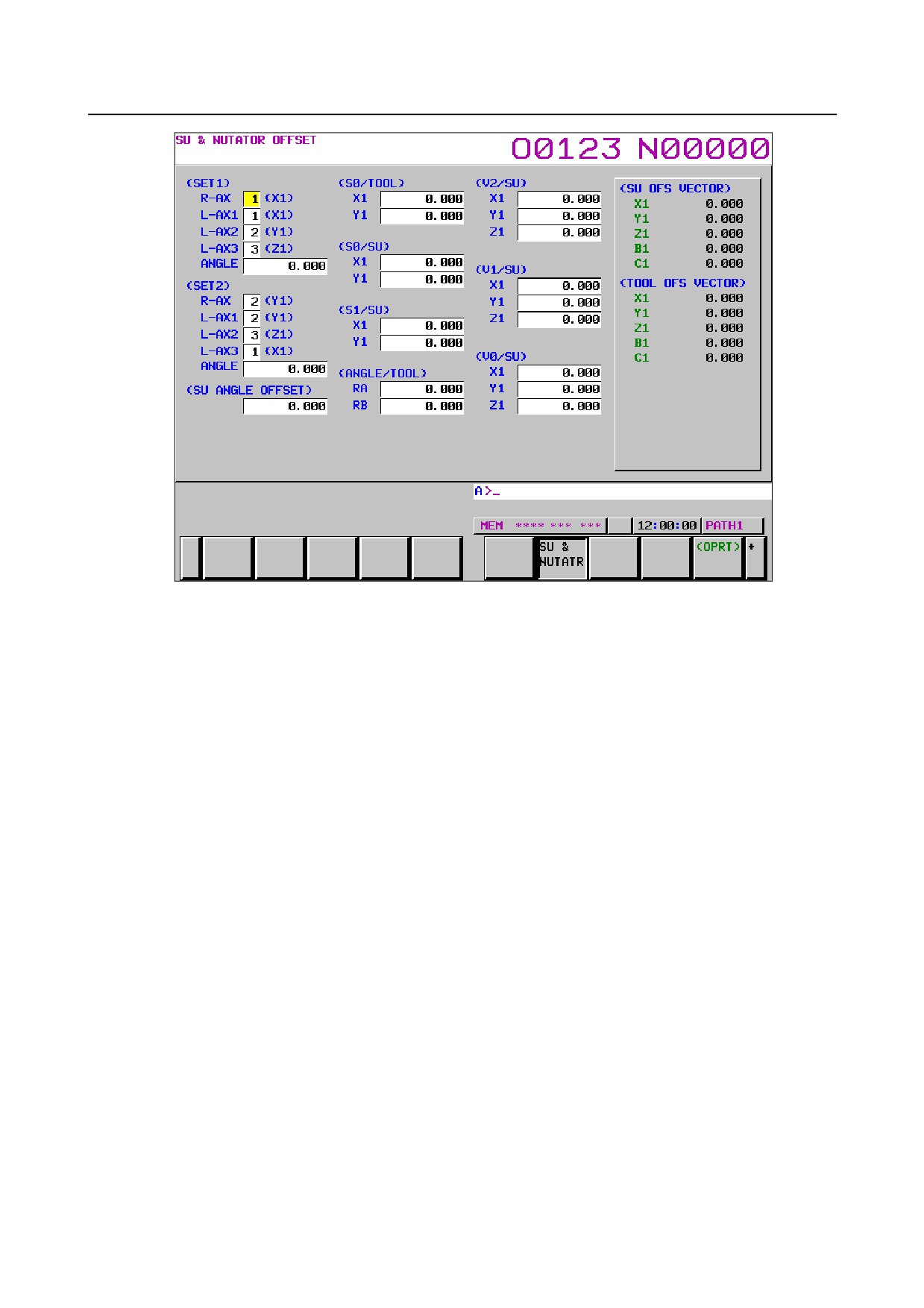
On the spindle unit compensation/nutating rotary head tool length compensation screen, the following
items are displayed:
• Parameters Nos. 25861 to 25888
• Spindle unit compensation vector
• Nutating rotary head tool length compensation vector
If bit 7 (SU3) of parameter No. 25860 is set to 1, parameter input is possible.
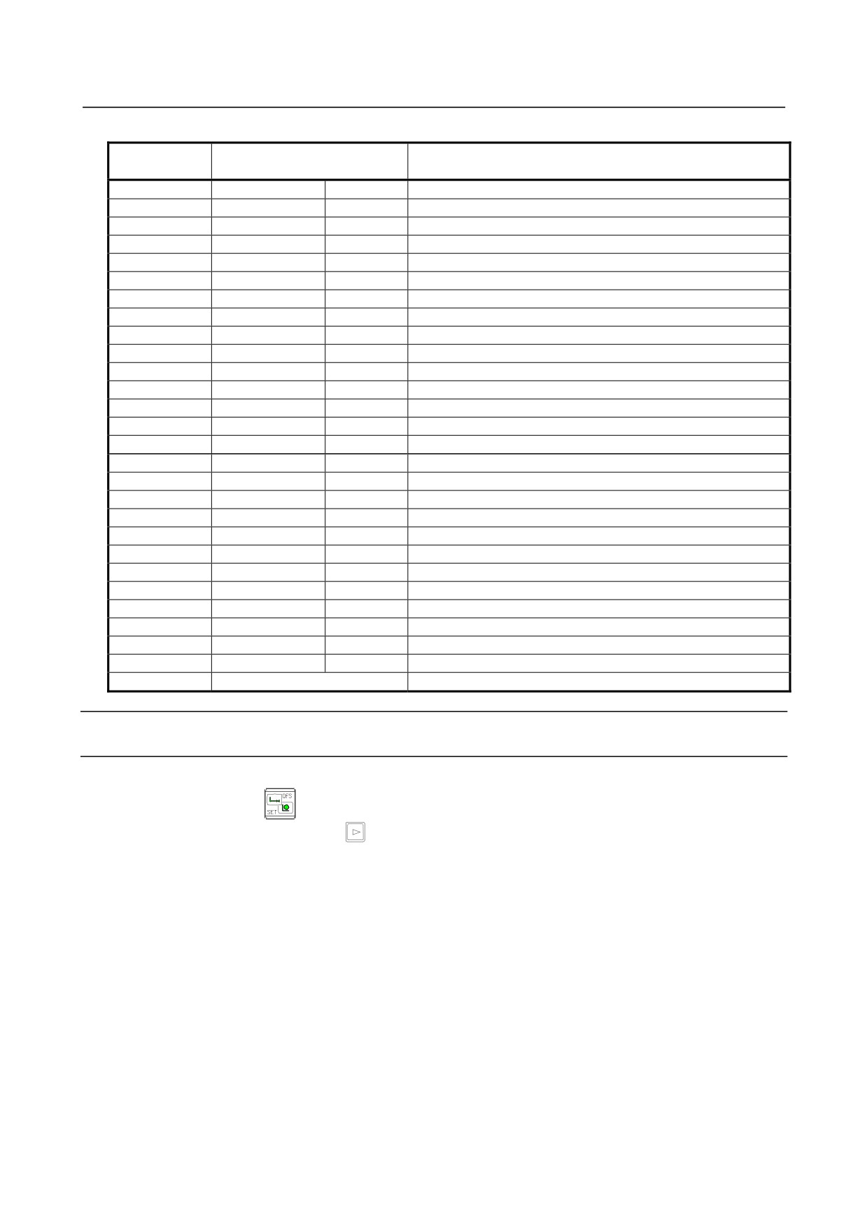
The following table shows the correspondence between the screen names and parameter numbers.
- 377 -
1.SETTING AND DISPLAYING DATA OPERATION
B-64484EN-2/02
Table 1.1.6 Parameter list
Parameter
Screen name
Description
number
25861
(SET1)
R-AX
Axis number of the rotation axis
(1st group)
25862
(SET1)
L-AX1
Axis number of the linear axis 1
(1st group)
25863
(SET1)
L-AX2
Axis number of the linear axis 2
(1st group)
25864
(SET1)
L-AX3
Axis number of the linear axis 3
(1st group)
25865
(SET1)
Inclination
Inclination
(1st group)
25866
(SET2)
R-AX
Axis number of the rotation axis
(2nd group)
25867
(SET2)
L-AX1
Axis number of the linear axis 1
(2nd group)
25868
(SET2)
L-AX2
Axis number of the linear axis 2
(2nd group)
25869
(SET2)
L-AX3
Axis number of the linear axis 3
(2nd group)
25870
(SET2)
Inclination
Inclination
(2nd group)
25871
(V2/SU)
1st line
Component of linear axis 1 of V2 vector
25872
(V2/SU)
2nd line
Component of linear axis 2 of V2 vector
25873
(V2/SU)
3rd line
Component of linear axis 3 of V2 vector
25874
(V1/SU)
1st line
Component of linear axis 1 of V1 vector
25875
(V1/SU)
2nd line
Component of linear axis 2 of V1 vector
25876
(V1/SU)
3rd line
Component of linear axis 3 of V1 vector
25877
(V0/SU)
1st line
Component of linear axis 1 of V0 vector
25878
(V0/SU)
2nd line
Component of linear axis 2 of V0 vector
25879
(V0/SU)
3rd line
Component of linear axis 3 of V0 vector
25880
(S0/SU)
1st line
Rotation axis standard angle of the 1st group
25881
(S0/SU)
2nd line
Rotation axis standard angle of the 2nd group
25882
(S1/SU)
1st line
Rotation axis compensation amount of the 1st group
25883
(S1/SU)
2nd line
Rotation axis compensation amount of the 2nd group
25884
(S0/TOOL)
1st line
Rotation axis standard angle of the 1st group
25885
(S0/TOOL)
2nd line
Rotation axis standard angle of the 2nd group
25886
(ANGLE/TOOL)
RA
Tool axis standard angle (in the plane by the linear axes 2-3)
25887
(ANGLE/TOOL)
RB
Tool axis standard angle (in the plane by the linear axes 3-1)
25888
(SU ANGLE OFFSET)
Inclination compensation amount
Spindle unit compensation/nutating rotary head tool length compensation display
screen
Procedure
1
Press function key
2
Press the continuous menu key
several times, until soft key [SU OFFSET] appears.
3
Press soft key [SU OFFSET].
The SU&NUTATOR OFFSET screen displays.
- 378 -
B-64484EN-2/02
OPERATION
1.SETTING AND DISPLAYING DATA
Fig. 1.1.6 SU&NUTATOR OFFSET screen
- 379 -
B-64484EN-2/02
APPENDIX
A.PARAMETERS
A PARAMETERS
This manual describes all parameters indicated in this manual.
For those parameters that are not indicated in this manual and other parameters, refer to the parameter
manual.
Appendix A, "PARAMETERS", consists of the following sections:
A.1 DESCRIPTION OF PARAMETERS
383
A.2 DATA TYPE
432
A.3 STANDARD PARAMETER SETTING TABLES
433
A.1 DESCRIPTION OF PARAMETERS
#7
#6
#5
#4
#3
#2
#1
#0
0001
FCV
[Input type] Setting input
[Data type] Bit path
#1 FCV Program format
0: Series 16 standard format
1: Series 15 format
NOTE
1 Programs created in the Series 15 program format can be used for
operation on the following functions:
1 Subprogram call M98
2 Multiple repetitive canned cycle G71.7 to G71.6
3 Drilling canned cycle G73, G74, G76, G80 to G89
2 When the program format used in the Series 15 is used for this
CNC, some limits may add. Refer to the Operator’s Manual.
#7
#6
#5
#4
#3
#2
#1
#0
1013
ISEx
ISDx
ISCx
ISAx
[Input type] Parameter input
[Data type] Bit axis
NOTE
When at least one of these parameters is set, the power must be
turned off before operation is continued.
#0 ISAx
#1 ISCx
#2 ISDx
#3 ISEx Increment system of each axis
Increment system
Bit 3 (ISE)
Bit 2 (ISD)
Bit 1 (ISC)
Bit 0 (ISA)
IS-A
0
0
0
1
IS-B
0
0
0
0
- 383 -
A.PARAMETERS
APPENDIX
B-64484EN-2/02
Increment system
Bit 3 (ISE)
Bit 2 (ISD)
Bit 1 (ISC)
Bit 0 (ISA)
IS-C
0
0
1
0
IS-D
0
1
0
0
IS-E
1
0
0
0
1020
Program axis name for each axis
[Input type] Parameter input
[Data type] Byte axis
[Valid data range] 65 to 67, 85 to 90
An axis name (axis name 1: parameter No. 1020) can be arbitrarily selected from A, B, C,
U, V, W, X, Y, and Z. (When G code system A is used with the lathe system, however, U,
V, and W are not selectable.) When bit 0 (EEA) of parameter No. 1000 is set to 1, the
length of an axis name can be extended to three characters by setting axis name 2
(parameter No. 1025) and axis name 3 (parameter No. 1026) (extended axis name).
For axis names 2 and 3, a character from 0 to 9 and A to Z of ASCII code can be
arbitrarily selected. However, the setting of axis name 3 for each axis is invalid if axis
name 2 is not set. Moreover, if a character from 0 to 9 is set as axis name 2, do not use a
character from A to Z as axis name 3.
(Tip) ASCII code
Axis name
X
Y
Z
A
B
C
U
V
W
Setting
88
89
90
65
66
67
85
86
87
When G code system A is used with the lathe system, and the character X, Y, Z, or C is
used as axis name 1 of an axis, a command with U, V, W, or H specified for axis name 1
represents an incremental programming for the axis.
NOTE
1 When a multiple repetitive canned cycle for turning is used, no
character other than X, Y, and Z can be used as the address of the
axis.
2 An address other than addresses A, B, and C cannot be used as
the address of a rotary axis used for the function for tool length
compensation in a specified direction or the tool center point
control function.
3 When the custom macro function is enabled, the same extended
axis name as a reserved word cannot be used. Such an extended
axis name is regarded as a reserved word.
Because of reserved words of custom macros, extended axis
names that start with the following two characters cannot be used:
AB, AC, AD, AN, AS, AT, AX, BC, BI, BP, CA, CL, CO, US, WH,
WR, XO, ZD, ZE, ZO, ZW
4 In a macro call, no extended axis name can be used as an
argument.
1022
Setting of each axis in the basic coordinate system
[Input type] Parameter input
[Data type] Byte axis
[Valid data range] 0 to 7
- 384 -
B-64484EN-2/02
APPENDIX
A.PARAMETERS
To determine a plane for circular interpolation, cutter compensation, and so forth (G17:
Xp-Yp plane, G18: Zp-Xp plane, G19: Yp-Zp plane) and a
3-dimensional tool
compensation space (XpYpZp), specify which of the basic three axes (X, Y, and Z) is
used for each control axis, or a parallel axis of which basic axis is used for each control
axis.
A basic axis (X, Y, or Z) can be specified only for one control axis.
Two or more control axes can be set as parallel axes for the same basic axis.
Setting
Meaning
0
Rotary axis (Neither the basic three axes nor a parallel axis )
1
X axis of the basic three axes
2
Y axis of the basic three axes
3
Z axis of the basic three axes
5
Axis parallel to the X axis
6
Axis parallel to the Y axis
7
Axis parallel to the Z axis
In general, the increment system and diameter/radius specification of an axis set as a
parallel axis are to be set in the same way as for the basic three axes.
1023
Number of the servo axis for each axis
NOTE
When this parameter is set, the power must be turned off before
operation is continued.
[Input type] Parameter input
[Data type] Byte axis
[Valid data range] 0 to Number of controlled axes
Set the servo axis for each control axis.
Usually set to same number as the control axis number.
The control axis number is the order number that is used for setting the axis-type
parameters or axis-type machine signals
• With an axis for which Cs contour control/spindle positioning is to be performed, set
-(spindle number) as the servo axis number.
Example)
When exercising Cs contour control on the fourth controlled axis by using the
first spindle, set -1.
• For tandem controlled axes or electronic gear box (EGB) controlled axes, two axes
need to be specified as one pair. So, make a setting as described below.
Tandem axis: For a master axis, set an odd (1, 3, 5, 7, ...) servo axis number. For a
slave axis to be paired, set a value obtained by adding 1 to the value
set for the master axis.
EGB axis: For a slave axis, set an odd (1, 3, 5, 7, ...) servo axis number. For a
dummy axis to be paired, set a value obtained by adding 1 to the value
set for the slave axis.
1031
Reference axis
[Input type] Parameter input
[Data type] Byte path
[Valid data range] 1 to Number of controlled axes
- 385 -
A.PARAMETERS
APPENDIX
B-64484EN-2/02
The unit of some parameters common to all axes such as those for dry run feedrate and
single-digit F1 feedrate may vary according to the increment system. An increment
system can be selected by a parameter on an axis-by-axis basis. So, the unit of those
parameters is to match the increment system of a reference axis. Set which axis to use as a
reference axis.
Among the basic three axes, the axis with the finest increment system is generally
selected as a reference axis.
#7
#6
#5
#4
#3
#2
#1
#0
1401
RF0
LRP
[Input type] Parameter input
[Data type] Bit path
#1 LRP Positioning (G00)
0: Positioning is performed with non-linear type positioning so that the tool moves
along each axis independently at rapid traverse.
1: Positioning is performed with linear interpolation so that the tool moves in a straight
line.
When using 3-dimensional coordinate system conversion, set this parameter to 1.
#4 RF0 When cutting feedrate override is 0% during rapid traverse,
0: The machine tool does not stop moving.
1: The machine tool stops moving.
#7
#6
#5
#4
#3
#2
#1
#0
1403
ROC
EDT
[Input type] Parameter input
[Data type] Bit path
#3 EDT The function for corner control by feedrate (for a gas cutting machine) is:
0: Disabled.
1: Enabled.
When the feedrate has reduced to the feedrate set in parameter No. 1474, from which the
system regards the number of accumulated pulses as being 0, the next block is executed.
#4 ROC In the threading cycle G76.7, rapid traverse override for retraction after threading is
finished is:
0: Effective
1: Not effective (Override of 100%)
1410
Dry run rate
[Input type] Parameter input
[Data type] Real path
[Unit of data] mm/min, inch/min, degree/min (machine unit)
[Min. unit of data] Depend on the increment system of the reference axis
[Valid data range] Refer to the standard parameter setting table (C)
(When the increment system is IS-B, 0.0 to +999000.0)
Set the dry run rate at the 100% position on the jog feedrate specification dial. The unit of
data depends on the increment system of the reference axis.
- 386 -