FANUC Series 30i-MODEL B, 31i-MODEL B, 32i-MODEL B. For Machining Center System. OPERATOR'S MANUAL - page 12
8.AXIS CONTROL FUNCTIONS
PROGRAMMING
B-64484EN-2/02
Explanation
Override of gear ratio for flexible synchronization
This function enables to override the commanded gear ratio of flexible synchronous control.
Program example
Axis configuration: X,Y,Z,C, and U
Setting of flexible synchronous control:
Master axis : Z, slave axis : U,
M code for turning on the flexible synchronization control mode : M50
M code for turning off the flexible synchronization control mode : M51
G90 G00 X100.0 Y75.0 Z120.0 C0 U0 ;
Move to the start point.
M50 ;
Start Z-U synchronization.
G81.1 Z100.0 Q-25.0 R10.0 F3000. ;
Start chopping.
……………………
……………………
G80 ;
Cancel chopping.
M51 ;
Cancel Z-U synchronization.
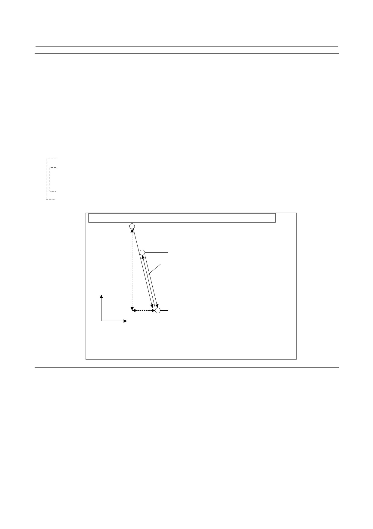
Movement of chopping function by flexible synchronous control
Point R
(1)
Upper dead point
Movement process :
(2)
(1):Movement from point R to lower dead
Zm
point.
(2):Movement from lower dead point to
upper dead point.
(3)
(3):Movement from upper dead point to
Z
lower dead point.
After (1), repeat (2) and (3).
Lower dead point
Xs
X
When flexible synchronization is applied to Z axis (master) and X axis (slave), Amount
of travel Xs of X axis is as follows:
Xs = Zm × Gear ratio for flexible synchronization (parameter No.5680 to No.5693)
× override signal of gear ratio for flexible synchronization
Notes
1
The parameter setting and notes for flexible synchronous control and chopping are applied to this
function.
2
Flexible synchronous control is started and canceled by the flexible synchronous control mode select
signal. To start or cancel flexible synchronization during automatic operation, control the select
signal using the M code set in the relevant parameter.
3
Chopping can be specified using the following two ways: Specifying chopping in the program and
using the chopping start signal. Chopping started by specifying it in the program cannot be canceled
by inputting the signal.
4
Be sure to start or cancel chopping in flexible synchronous control for this function. (See “Program
example”.)
5
Before synchronization starts, the tool must be positioned along the slave axis.
6
When the servo delay compensation function during chopping operation is used with this function,
the compensation amount for the master axis is multiplied by the gear ratio of flexible
synchronization, and the result is output to the slave axis. If you want to adjust the compensation
- 322 -
B-64484EN-2/02
PROGRAMMING
8.AXIS CONTROL FUNCTIONS
amount for the slave axis, adjust the gear ratio using override signals of gear ratio for flexible
synchronization.
7
When this function is used for a rotation axis, the servo delay compensation function during
chopping operation cannot be used.
8.3
PARALLEL AXIS CONTROL
Overview
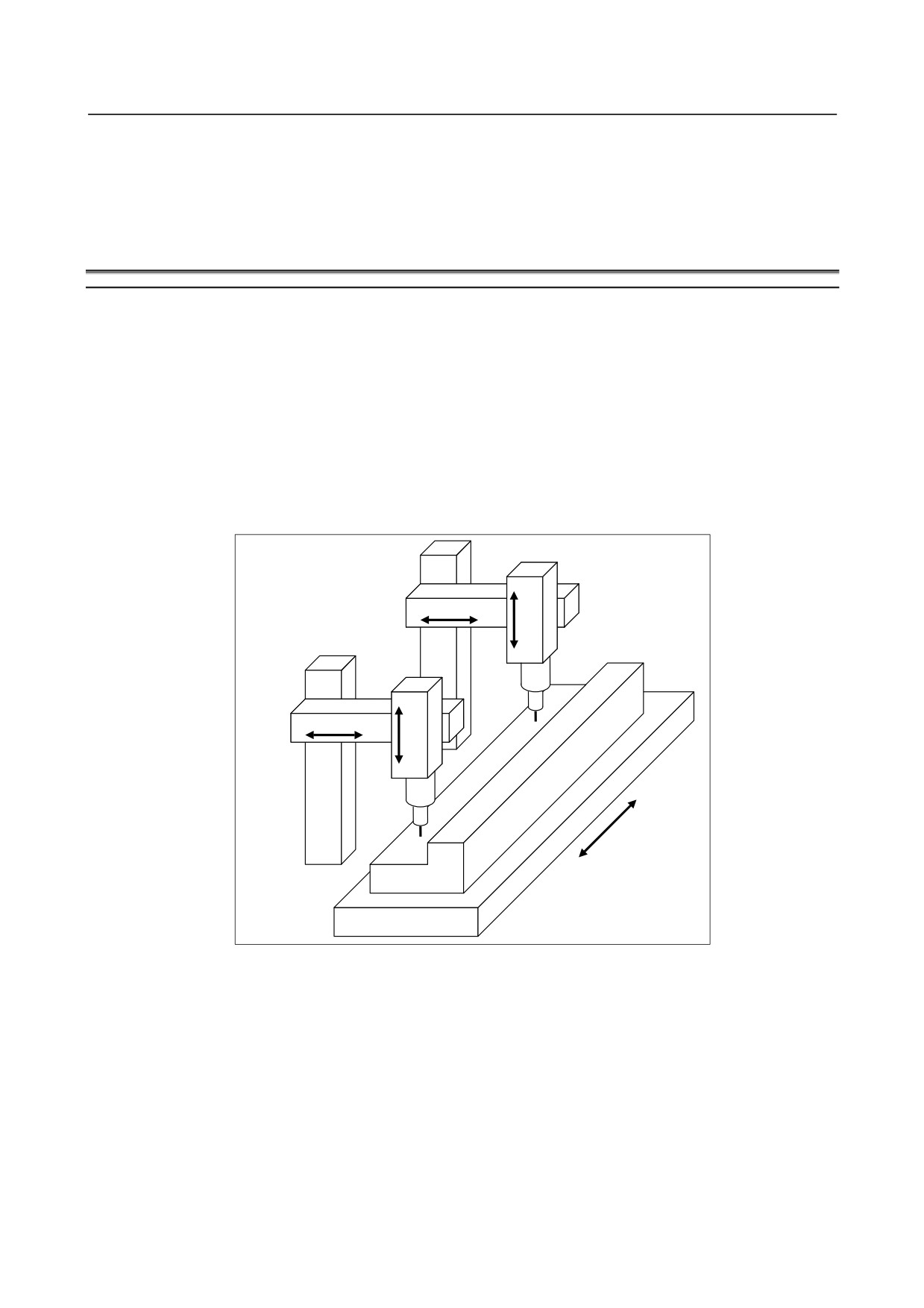
If a machine contains multiple heads and tables to machine multiple workpieces simultaneously, it is
possible to move multiple controlled axes assigned the same axis name, by using a move command for a
single program axis. This is called parallel operation.
Two or more axes that are moved simultaneously when a command for a single program axis, i.e., a
command with a single address, is issued are called parallel axes.
This function is effective to automatic operation, MDI operation, and manual numerical commands on
1-path machining centers. In manual operation, parallel operation is not possible, each controlled axis is
moved independently.
In parallel operation, the controlled axes belonging to a single program axis are moved in the same way in
principle. It is, however, possible to select specified ones from among multiple parallel axes and move
them (park the other axes), using appropriate external signals.
Y2
Z2
Y1
Z1
X
Fig. 8.3 (a)
In the Fig. 8.3 (a), Y1 and Y2 are parallel axes, and are operated in parallel with a command for a single
address Y.
Z1 and Z2 are also parallel axes, and are operated in parallel with a command for a single address Z.
There are two movements of each parallel axis, which are selected with appropriate external input signals.
• Normal (parking off)
The axis moves as commanded.
• Parking (parking on)
The axis ignores the command, and does not move.
- 323 -

8.AXIS CONTROL FUNCTIONS
PROGRAMMING
B-64484EN-2/02
NOTE
1
The parallel axis control function is effective to 1-path machining centers only.
2
The parallel axis control function does not support the functions below.
(1)
Smooth interpolation
(2)
Nano smoothing
(3)
3-dimensional coordinate system conversion
(4)
3-dimensional tool compensation
(5)
Tool length compensation in tool axis direction
(6)
Tool center point control
(7)
Tool posture control
(8)
3-dimensional cutter compensation
(9)
Tilted working plane command
(10) Nano smoothing 2
(11) Workpiece setting error compensation
(12) Tandem control
(13) Twin table control
(14) Synchronous/Composite control
(15) Superimposed Control
3
If coordinate system rotation (G68) is to be specified, the program coordinate
systems of the parallel axes must be identical. In the immediately preceding
block, therefore, it is necessary to execute a move command on all parallel axes,
using an absolute command (G90). (As long as the command is executed, there
may be any axes in parking.)
If the program coordinate systems of the parallel axes are not identical, alarm
PS0508, “G CODE TO NEED G90(PAC)” is issued.
Axis configuration in parallel axis control
The following limitations are imposed on the axis configuration in parallel axis control:
(1) All parallel axes must have the same axis name.
If different axis names are set, the axes cannot be recognized as parallel axes.
(2) To distinguish parallel axes from one another, specify the subscript for each of the axes.
(3) Parallel axes are regarded as controlled axes, and their respective speeds are added to the actual
cutting feedrate display. It is possible not to add the speed of a slave axis to the actual cutting
feedrate display (by setting bit 3 (NDFx) of parameter No. 3115 to 1).
(4) To perform circular interpolation or cutter compensation, it is necessary to specify to which basic
coordinate system each axis belongs, using parameter No. 1022. At this time, make the same settings
for parallel axes.
(5) If parallel axis control is used together with feed axis synchronization control, make sure that the
axes subject to feed axis synchronization control have different axis names.
The following shows an example in which parallel axis control is performed on a machine with five axes
X, Y1, Y2, Z1, and Z2.
Number of controlled axes = 5
Axis
Displayed
Axis name
Subscript
Basic coordinate axis setting
Servo axis number
number
axis name
(No. 1020)
(No. 3131)
(No. 1022)
(No. 1023)
1
X
88
0
1
1
2
Y1
89
1
2
2
3
Y2
89
2
2
3
4
Z1
90
1
3
4
5
Z2
90
2
3
5
- 324 -
B-64484EN-2/02
PROGRAMMING
8.AXIS CONTROL FUNCTIONS
Selecting coordinate systems on parallel axes
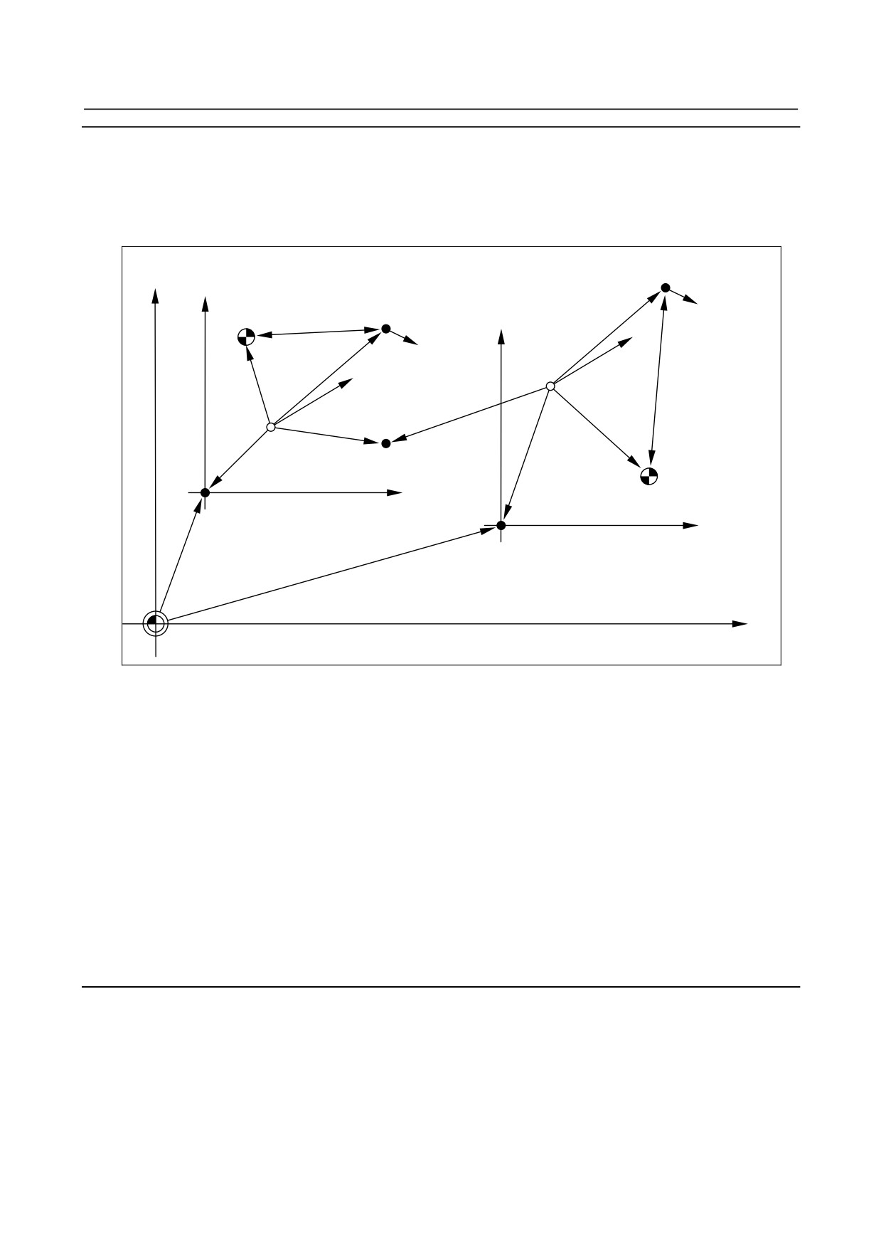
It is possible to set individual workpiece coordinate system offset values for the controlled axes belonging
to the same program axis. This makes it possible to create a program by considering independent
coordinate systems for the individual controlled axes.
For example, if there are two heads, each of which
have two controlled axes (X and Y), the tool
movement is as shown below.
Mid-point of head 2
Y
Y1
Reference position
Mid-point of head 1
of head 1
Y
2
(f)
(e)
Current position of
(f)
tool of head 2
(a)
(d)
(a)
(c)
(d)
(c)
(b)
Current position of
(b)
tool of head 1
(e)
Reference position of
Workpiece coordinate system of
X1
head 2
head 1
Workpiece coordinate system
X2
Workpiece origin offset of
of head 2
head 1
Workpiece origin offset
of head 2
Origin of machine coordinate system
X
(a)
Movement with an incremental command
(Example) G91 X_ Y_;
(b)
Movement with an absolute command
(Example) G90 X0 Y0;
(c)
Move command with the machine coordinate system
Each axis moves to a single point on the machine coordinate system.
(Example) G90 G53 X_ Y_;
(d)
Automatic reference position return (G28, G30)
Each axis returns to the reference position of its controlled axis individually set with a parameter.
(Example) G91 G28 X0 Y0;
(e)
Reference position return check (G27)
A check is performed to see if each axis has returned to its reference position.
(Example) G91 G27 X0 Y0;
(f)
Automatic return to the reference position (G29)
Each axis is positioned to the position specified via its mid-point.
(Example) G91 G29 X30. Y50.;
Tool length compensation and tool offset on parallel axes
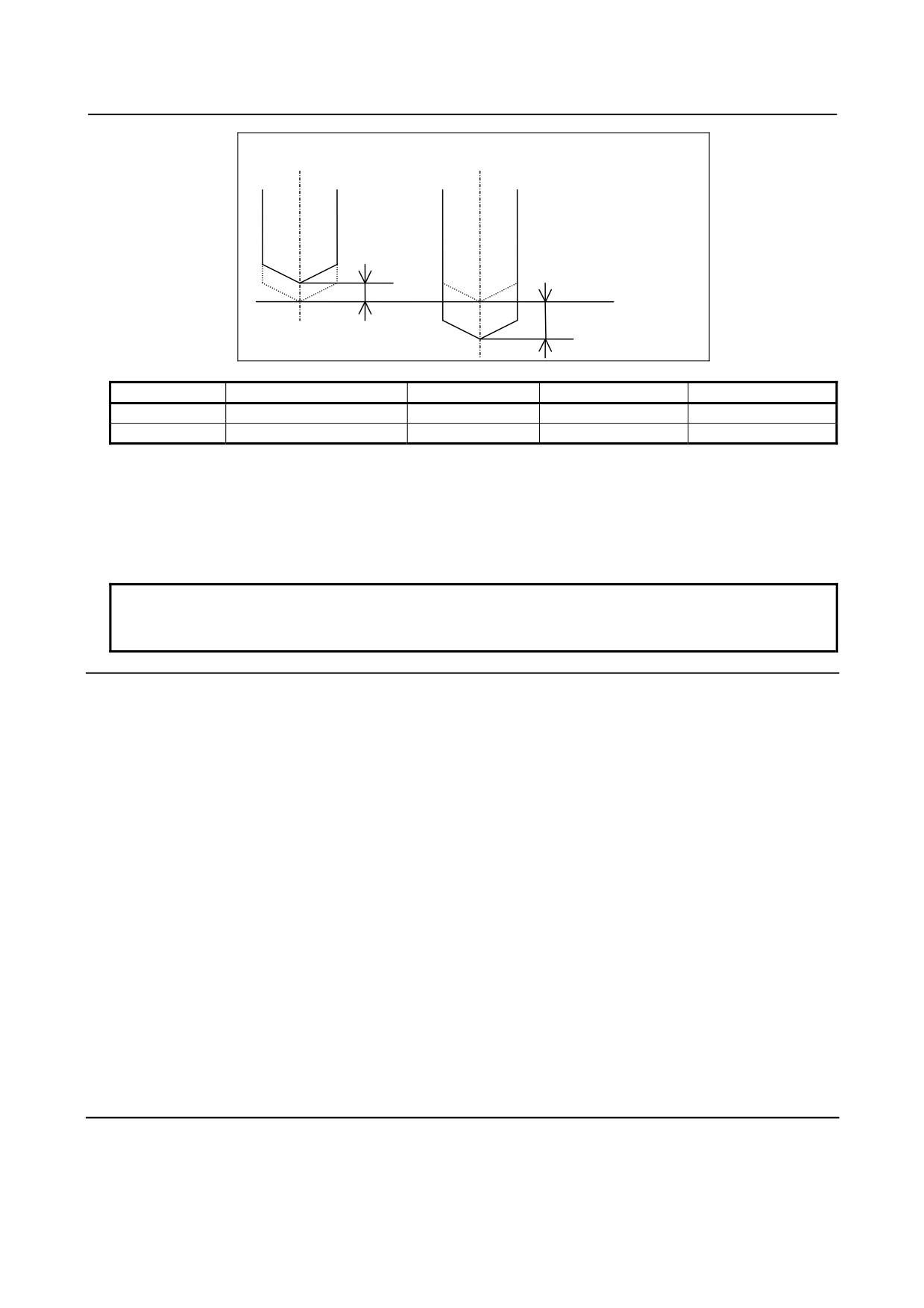
It is possible to set the difference between an H code number and the offset data number selected in
accordance with this number, i.e., bias value, in a parameter for each axis, and perform tool length
compensation on a different tool for each axis. It is also possible to apply an offset in the case of the tool
offset function.
Set the bias value of tool length compensation in parameter No. 10361.
Set the bias amount of tool offset in parameter No. 10360.
- 325 -
8.AXIS CONTROL FUNCTIONS
PROGRAMMING
B-64484EN-2/02
Tool of head 1
Tool of head 2
ε1
ε2
Programmed
position
Head
Offset number
Bias value
Offset data number
Offset value
Head 1
07
10
17
ε1
Head 2
07
20
27
ε2
If parallel operation is to be performed with the third and fourth axes as the Z1- and Z2-axes, let us
assume, for example, that 10 is set in parameter No. 10361 as the bias value for the Z1-axis, and 20 for
the Z2-axis. If a tool length compensation command G43 H07 ; is specified, tool length compensation is
performed by using the offset data number 17 (= 07 + 10) as the offset value for the tool of head 1 and the
offset data number 27 (= 07 + 20) as the offset value for the tool of head 2.
NOTE
The offset value for the offset number 00, i.e., H00, is always 0 regardless of the
bias value.
Travel distances on parallel axes
The travel distances on parallel axes differ as described below depending on whether the command is an
incremental or absolute one.
(1) For an incremental command
•
Rapid traverse and linear interpolation
The travel distances on all parallel axes are the same.
•
Circular interpolation and helical interpolation
The travel distances on all parallel axes are the same.
This means that the same arc is interpolated simultaneously for a multiple number of times.
(2) For an absolute command
•
Rapid traverse and linear interpolation
The end points of all parallel axes are the same.
This means that if the start positions differ, the travel distances on the parallel axes differ.
•
Circular interpolation and helical interpolation
Interpolation is performed using the data for the first un-parked one in the list of controlled
axes, and for the other parallel axes, the same data as that used for interpolation is output.
This means that even if the command is an absolute one, if the start position of a parallel axis differs
from that of the axis the data for which is used for interpolation, the end point differs from the
specified one.
Feedrate calculation
For linear interpolation, the feedrate during parallel operation is calculated by selecting the one of the
parallel axes that has the longest travel distance. The data for the other parallel axes is not reflected in the
calculation of the feedrate.
- 326 -
B-64484EN-2/02
PROGRAMMING
8.AXIS CONTROL FUNCTIONS
(Example)
If the X-axis has parallel axes (X1, X2)
Start point position
X1:0.0
X2:5.0
Y :0.0
Command
G01 G90 X10. Y20. F500
The travel distance on X1 is 10.0 and that on X2 is 5.0. Thus, the feedrate is calculated using the distance
of X1, which is longer, as follows:
Assume that the feedrate on each axis is
2
2
L=
10
+ 20
X1: 500 * 10 / L
X2: 500 * 5 / L
Y : 500 * 20 / L
- 327 -
9.GAS CUTTING MACHINE
PROGRAMMING
B-64484EN-2/02
9 GAS CUTTING MACHINE
Chapter 9, "GAS CUTTING MACHINE", consists of the following sections:
9.1 TOOL OFFSET B
328
9.2 CONER CONTROL BY FEED RATE
331
9.3 AUTOMATIC EXACT STOP CHECK
333
9.4 AXIS SWITCHING
336
9.5 GENTLE CURVE CUTTING
339
9.6 GENTLE NORMAL DIRECTION CONTROL
341
9.1
TOOL OFFSET B
Overview
With the G43H_ or G44H_ command, tool offset not affected by mirror image can be applied.
With the G49 command, tool offset can be canceled without being affected by mirror image.
The offset axes are the first axis and second axis for plane selection.
Format
G43 H_ ; Shifts the coordinate system by an offset value in the + direction.
G44 H_ ; Shifts the coordinate system by an offset value in the - direction.
G49 ; or G43 (or G44) H0 ; Tool offset B cancel
G43 (or G44) : Tool offset in the + (or -) direction
G49 (or H0)
: Tool offset cancel
H_
:
Tool offset number
(G43,G44,G49: Modal G code)
Explanation
By setting bit 0 (GOB) of parameter No. 5033 to 1 and specifying G43H_; or G44H_;, tool offset not
affected by mirror image can be applied. The difference between the programmed tool position and the
tool position actually used for machining can be corrected using this function without modifying the
program, by setting the difference in the offset memory.
By using the H code, specify the offset memory number where a tool offset value is set.
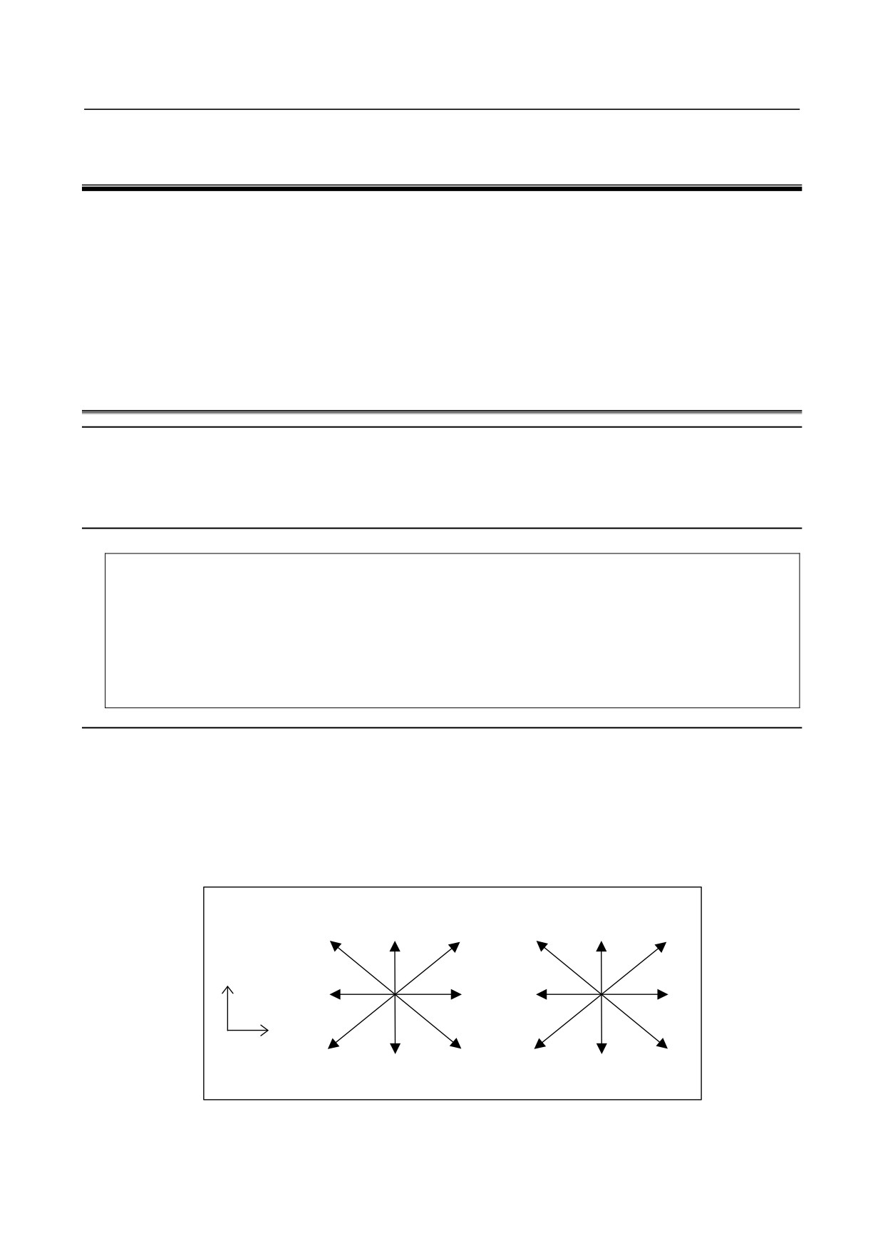
As shown in Fig. 9.1 (a), eight offset directions are present for each of G43 and G44. Select a direction
with parameter No. 5032.
When G43 is specified
When G44 is specified
2
6
3
1
7
5
Y
4
0
0
4
X
5
7
1
3
6
2
Fig. 9.1 (a)
- 328 -
B-64484EN-2/02
PROGRAMMING
9.GAS CUTTING MACHINE
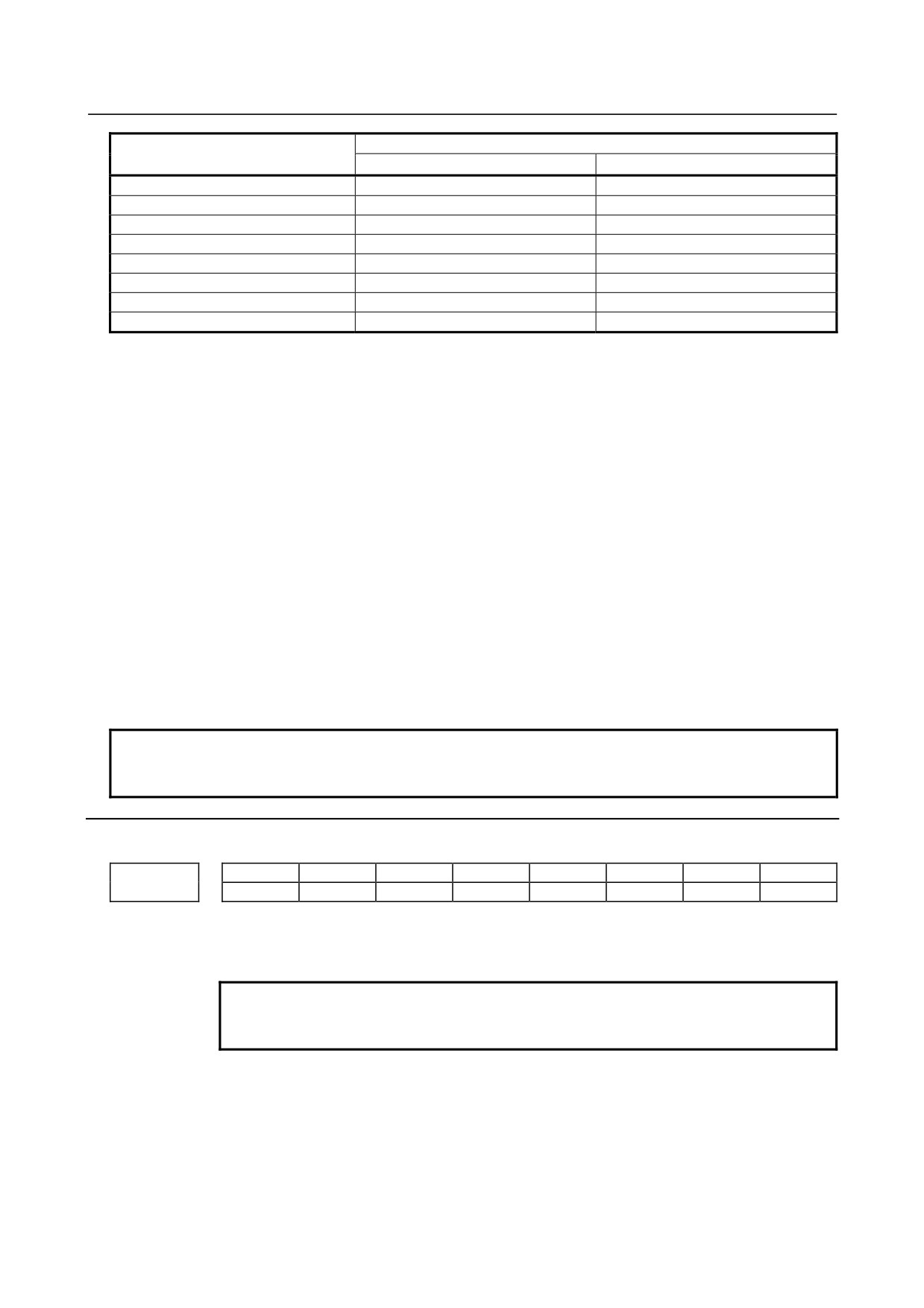
Offset direction
Value set in parameter No. 5032
G43
G44
0
X+a
X-a
1
X+a Y+a
X-a Y-a
2
Y+a
Y-a
3
X-a Y+a
X+a Y-a
4
X-a
X+a
5
X-a Y-a
X+a Y+a
6
Y-a
Y+a
7
X+a Y-a
X-a Y+a
a:
Offset value set in the offset memory number specified with the H code
By specifying
G49 ;
tool offset can be canceled without being affected by mirror image.
For example, this function can correct the difference between the position of the nozzle of the gas cutting
machine actually used for machining and the position of the marking pen for drawing used to check the
program, without modifying the program.
As in the sample program indicated below, the program need not be modified if the difference between
the position of the nozzle of the gas cutting machine and the position of the marking pen is set as an offset
value in offset number 02, and the optional block skip signal BDTn is set to 1 to perform gas cutting or is
set to 0 to perform marking.
O0001;
:
/G43 H02;
:
/G49;
:
%
NOTE
In a G43, G44, or G49 block, no move command must be specified.
Otherwise, an alarm is issued.
Parameter
#7
#6
#5
#4
#3
#2
#1
#0
5033
GOB
[Input type] Parameter input
[Data type] Bit path
NOTE
When this parameter is set, the power must be turned off before
operation is continued.
#0 GOB The tool offset B function (for a gas cutting machine) is:
0: Disabled.
1: Enabled.
- 329 -
9.GAS CUTTING MACHINE
PROGRAMMING
B-64484EN-2/02
5032
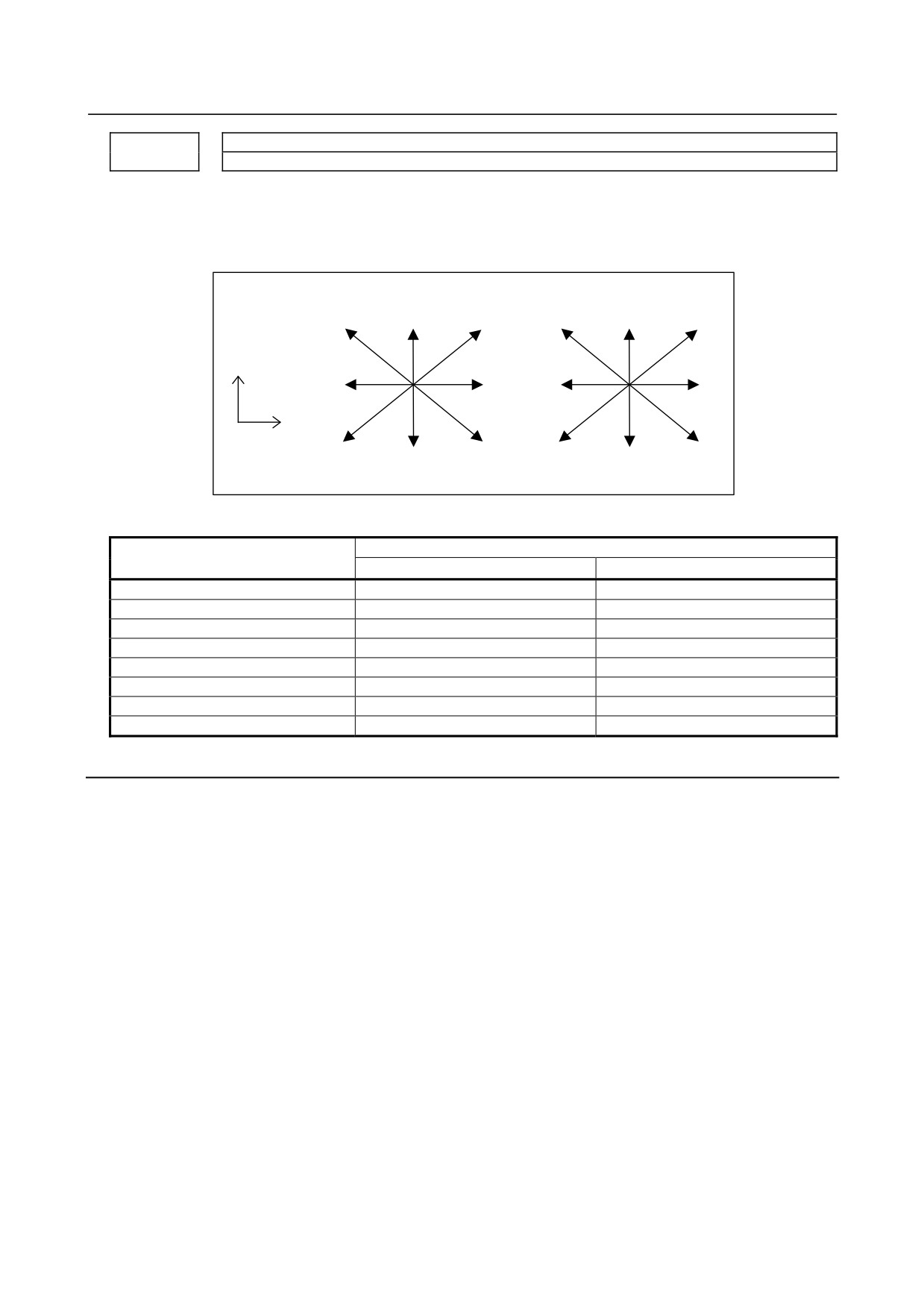
Direction of tool offset B
[Input type] Parameter input
[Data type] Byte path
[Valid data range]
0 to 7
Specify the offset direction of tool offset B (G43, G44).
When G43 is specified
When G44 is specified
2
6
3
1
7
5
Y
4
0
0
4
X
5
7
1
3
6
2
Fig. 9.1 (b)
Offset direction
Value set in parameter No. 5032
G43
G44
0
X+a
X-a
1
X+a Y+a
X-a Y-a
2
Y+a
Y-a
3
X-a Y+a
X+a Y-a
4
X-a
X+a
5
X-a Y-a
X+a Y+a
6
Y-a
Y+a
7
X+a Y-a
X-a Y+a
a:
Offset value set in the offset memory number specified with the H code
Note
• This function is optional. The tool offset B function needs to be specified.
• This function can be used only with the M series.
- 330 -
B-64484EN-2/02
PROGRAMMING
9.GAS CUTTING MACHINE
9.2
CONER CONTROL BY FEED RATE
Overview
If a block for cutting feed is followed by another block for cutting feed, the number of accumulated
pulses in the automatic acceleration/deceleration circuit of each axis in the block being executed is
assumed to be 0 and machining proceeds to the next block when the feedrate being decelerated on each
axis with the automatic acceleration/deceleration circuit has decreased to or below the feedrate set in
parameter No. 1474.
Explanation
If a block (block A) for cutting feed is followed by another block (block B) for cutting feed, the number
of accumulated pulses in the automatic acceleration/deceleration circuit of each axis in block A is
assumed to be 0 and machining proceeds to block B when the feedrate being decelerated on each axis
with the automatic acceleration/deceleration circuit has decreased to or below the feedrate set in
parameter No. 1474.
This function is enabled when block A is followed by block B and one of 1) through 4) is applicable. In
Fig. 9.2 (a), for example, there are accumulated pulses in the shaded area at time t, but machining
proceeds to the next block because the feedrate decelerated by the automatic acceleration/deceleration
circuit has decreased to or below the parameter-set value.
1)
Block A specifies G09 (exact stop check).
2)
Block A is in the G61 mode (exact stop check mode).
3)
In the automatic exact stop check mode, the angle formed by block A and block B is equal to or less
than the automatic exact stop check critical angle (parameter No. 1496).
4)
The in-position check signal SMZ <Gn053.6> is set to 1.
Block A
Block B
Parameter-set
feedrate
t
Time
Fig. 9.2 (a)
Please refer to Subsection, “In-position check” in Connection Manual (FUNCTION) (B-64483EN-1)
about the in-position check signal.
Parameter
#7
#6
#5
#4
#3
#2
#1
#0
1403
EDT
[Input type] Parameter input
[Data type] Bit path
- 331 -
9.GAS CUTTING MACHINE
PROGRAMMING
B-64484EN-2/02
#3 EDT The function for corner control by feedrate (for a gas cutting machine) is:
0: Disabled.
1: Enabled.
When the feedrate has reduced to the feedrate set in parameter No. 1474, from which the
system regards the number of accumulated pulses as being 0, the next block is executed.
1474
Feedrate regarded as accumulated pulse 0. (corner control by feedrate (for gas cutting machine))
[Input type] Parameter input
[Data type] Real axis
[Unit of data] mm/min,inch/min,deg/min (machine unit)
[Valid data range] 0 to 32767
When a cutting feed block (block A) is followed by another cutting feed block (block B),
execution proceeds to block B if the feedrate in the automatic acceleration/deceleration
circuit for each axis is reduced to the setting of this parameter, and the number of
accumulated pulses in the automatic acceleration/deceleration circuit is assumed to be 0.
This setting is used for corner control by feedrate (for a gas cutting machine).
Note
1)
This function is optional. The function for corner control by feedrate needs to be specified.
2)
This function can be used only with the M series.
3)
If a block for cutting feed is followed by a block specifying a miscellaneous function only or a block
for rapid traverse, machining proceeds to the next block when the number of accumulated pulses has
actually decreased to 0.
4)
When enabling this function by setting bit 3 (EDT) of parameter No. 1403 to 1, set bit 5 (NCI) of
parameter No. 1601 to 1 and check only that the specified feedrate is 0 at deceleration time (delay in
acceleration/deceleration is 0).
5)
If a value other than 0 is specified in parameter No. 1474, the number of accumulated pulses in the
automatic acceleration/deceleration circuit of each axis is assumed to be 0 and machining proceeds
to the next block when the feedrate being decelerated on each axis with the automatic
acceleration/deceleration circuit has decreased to or below the feedrate set in parameter No. 1474. So,
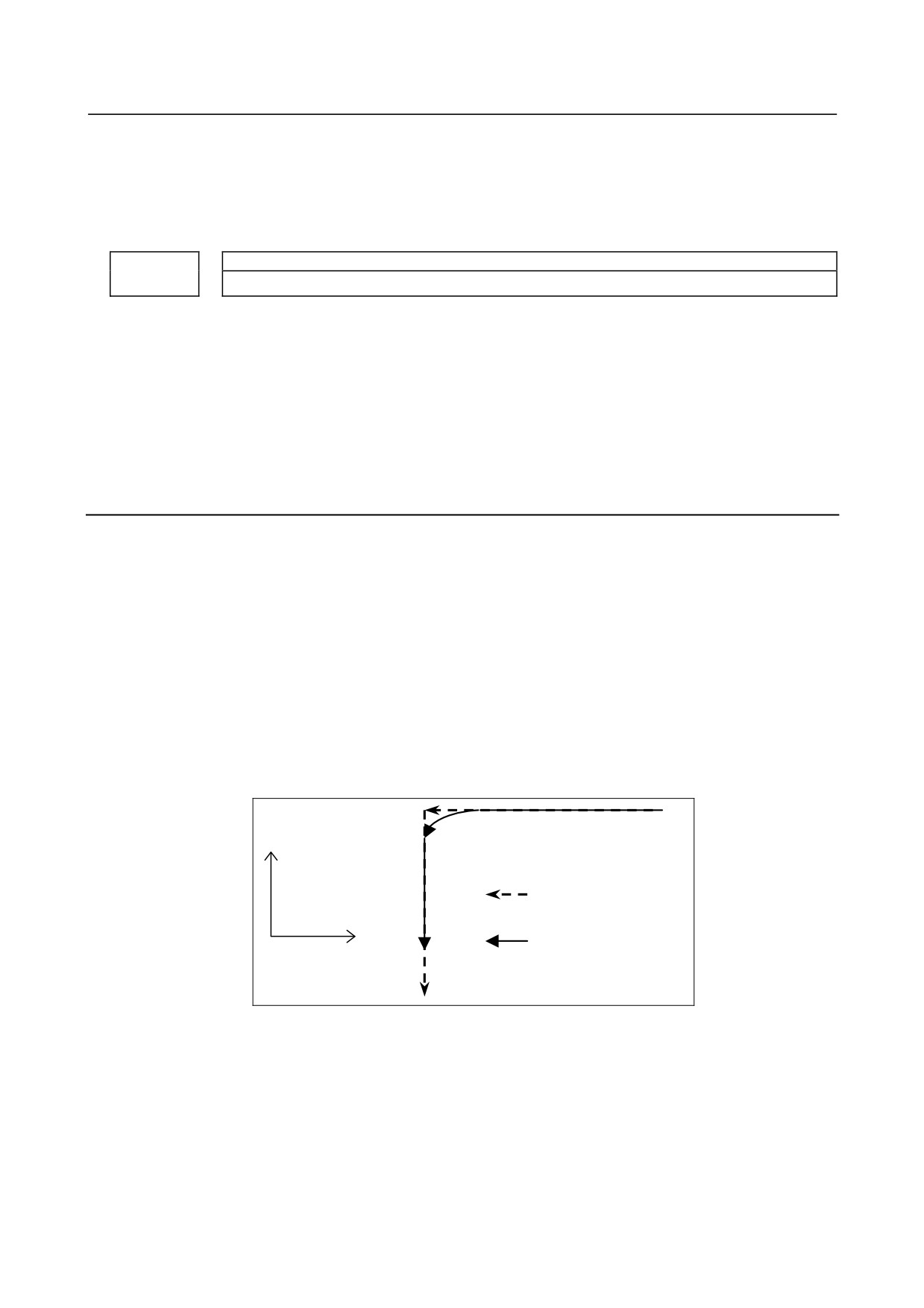
the path at a corner may be round as shown below (Fig. 9.2 (b)).
Y
Programmed path
X
Actual tool center path
Fig. 9.2 (b)
So, when a sharp corner is needed particularly, insert a block such as for dwell (G04) between
successive blocks for cutting feed.
<Example>
G09 G01 X Y
;
G04 X0;
G09 G01 X Y
;
6)
When acceleration/deceleration before interpolation is performed, this function is disabled.
7)
If feed per revolution is specified in one of successive blocks, this function is disabled.
- 332 -

B-64484EN-2/02
PROGRAMMING
9.GAS CUTTING MACHINE
9.3
AUTOMATIC EXACT STOP CHECK
Overview
This function checks the corner inner angle between successive blocks specifying linear interpolation
(G01) or circular interpolation (G02, G03), and performs an exact stop automatically between the blocks
if the angle is equal to or less than the parameter-set critical angle.
Explanation
When successive blocks specify linear interpolation (G01) or circular interpolation (G02, G03) in the
cutting mode (G64), this function checks the corner inner angle between the blocks on the currently
selected plane and determine whether to automatically perform an exact stop. In the figure below, an
exact stop is automatically performed at the end of block A if the corner inner angle θ is equal to or less
than the critical angle set in parameter No. 1496. This operation is equivalent to operation performed
when an exact stop (G09) is specified in block A.
(1)
(2)
A (G01)
A (G01)
θ
B (G01)
θ
B (G03)
(3)
(4)
A (G02)
A (G02)
θ
θ
B (G01)
B (G02)
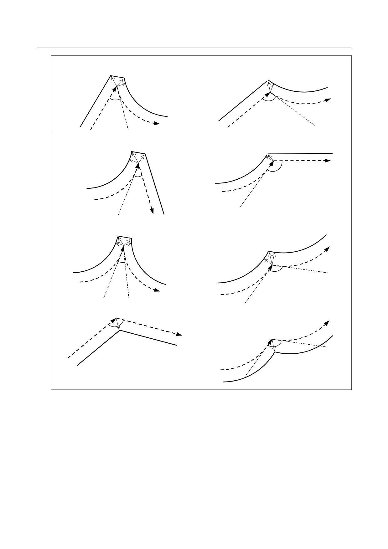
In the tool radius compensation mode as well, an automatic exact stop check is made for the corner inner
angles of the programmed path. At this time, an exact stop is performed at points A and B in the figure
below. (Point S represents a single-block stop point.)
(1)
A
A (S)
Offset vector
•
•B (S)
•
Post-offset path
Programmed path
θ
θ
- 333 -
9.GAS CUTTING MACHINE
PROGRAMMING
B-64484EN-2/02
(2)
A
A
•
• B (S)
• S
θ
θ
(3)
A (S)
A •
•B (S)
•
θ
θ
(4)
A
•
• B (S)
A (S)
•
θ
θ
(5)
θ
•
A (S)
θ
•
A (S)
If a small block specifies linear interpolation (G01) and also specifies the amounts of movement on the
two axes on the currently selected plane that are less than the value set in parameter No. 1497, the exact
stop check function can be disabled in the block.
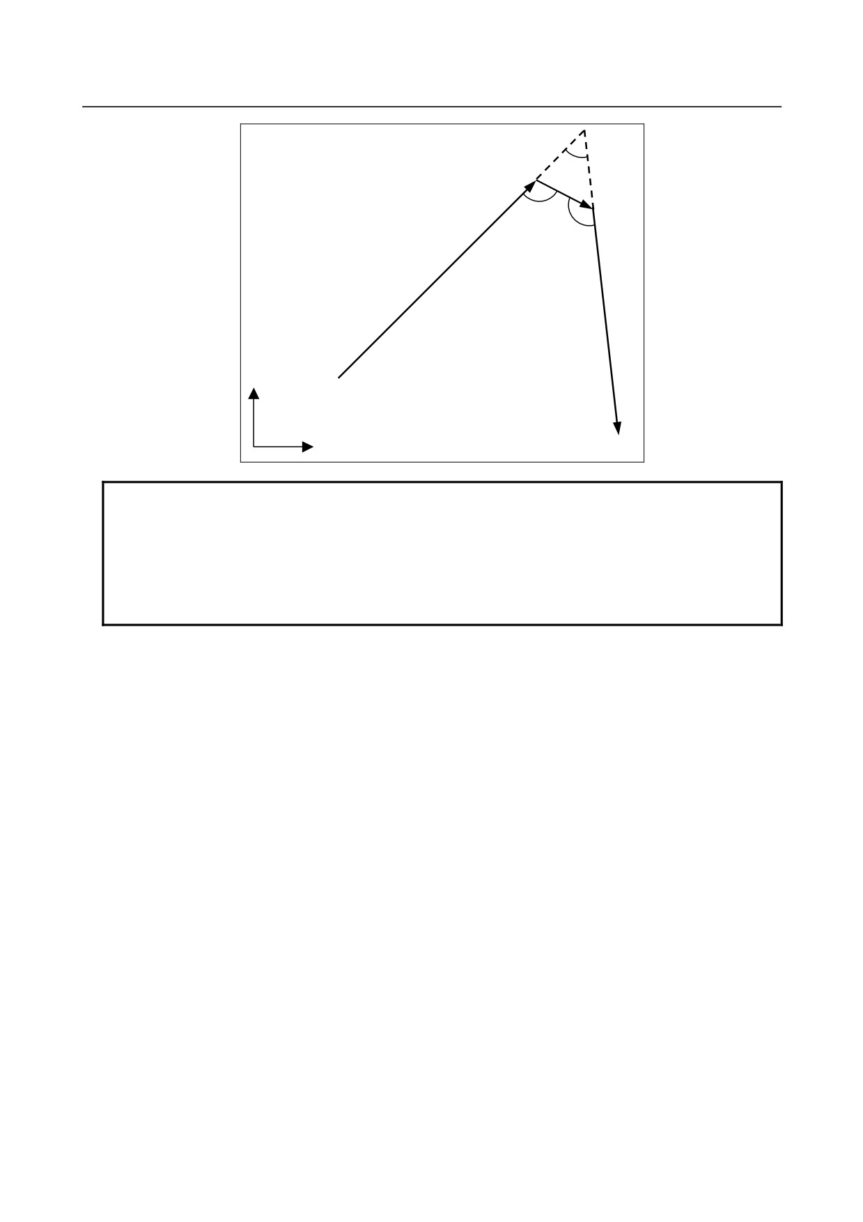
When linear interpolation (G01) is performed for A→B→C→D, an automatic exact stop check is made at
point B based on angle θ1 formed by lines AB and BC and at point C based on angle θ2 formed by lines
BC and CD. If the amount of movement on each of the two axes (X-axis and Y-axis in the figure below)
in the block for BC is less than the value set in parameter No. 1497, an automatic exact stop check is
made at point C based on angle θ3 formed by lines AB and CD.
- 334 -
B-64484EN-2/02
PROGRAMMING
9.GAS CUTTING MACHINE
θ3
B
θ1
C
θ2
X
A
G17 plane
Y
D
NOTE
1 If successive small blocks specify a value less than the value set in parameter
No. 1497, the automatic exact stop check function is disabled in the first small
block and enabled in the next block, and this disable/enable cycle is repeated for
the rest.
2 In the cutter compensation mode, the automatic exact stop check function
cannot be disabled by parameter No. 1497.
- 335 -
9.GAS CUTTING MACHINE
PROGRAMMING
B-64484EN-2/02
9.4
AXIS SWITCHING
Overview
The machine axis to be actually used for movement by specifying X, Y, or Z in memory operation, DNC
operation, or MDI operation can be switched by using the setting data (No. 10371) or the switch on the
machine operator’s panel.
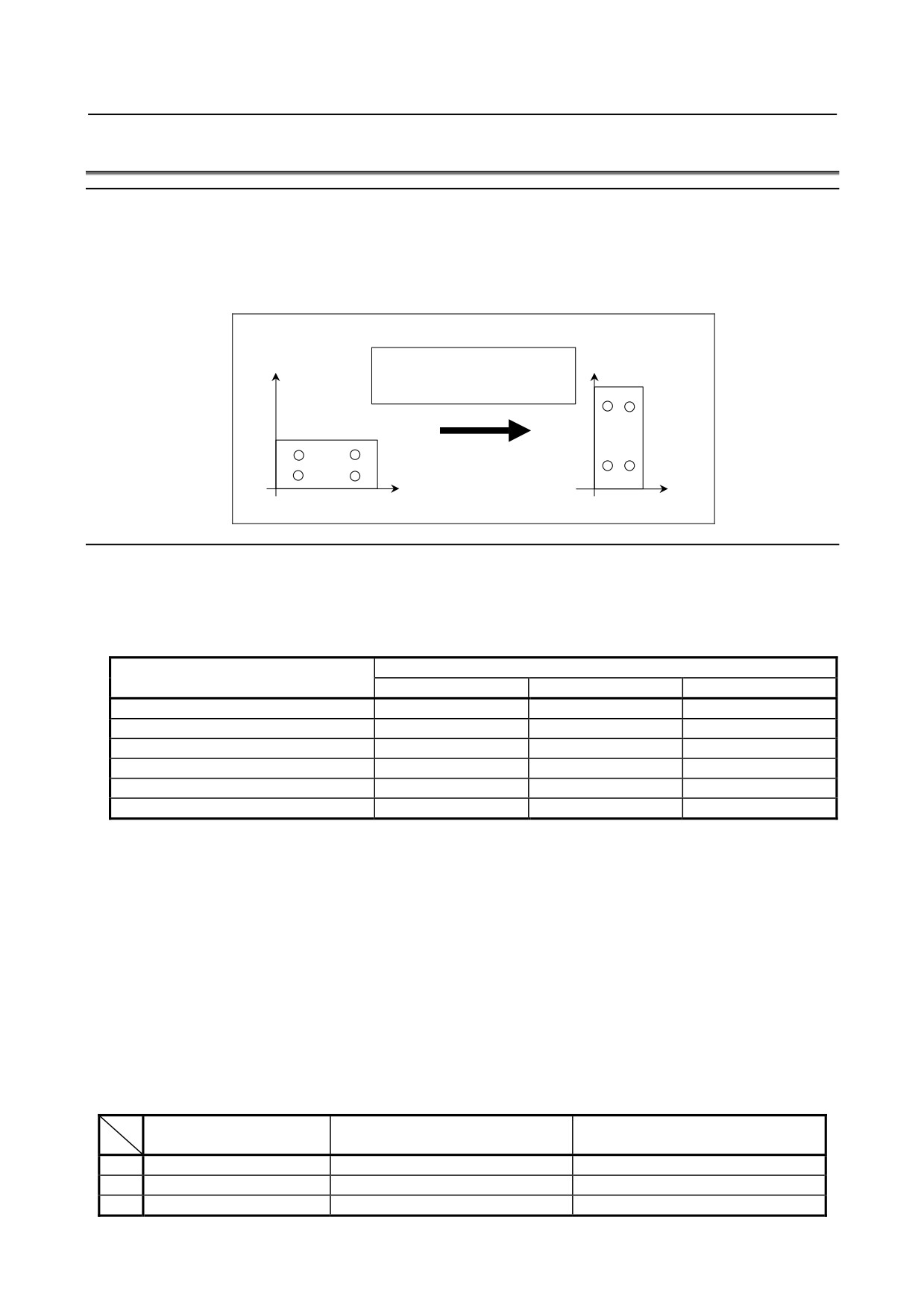
As shown in the example below, this function is useful when the coordinates where a workpiece is
actually set are changed from the programmed coordinates.
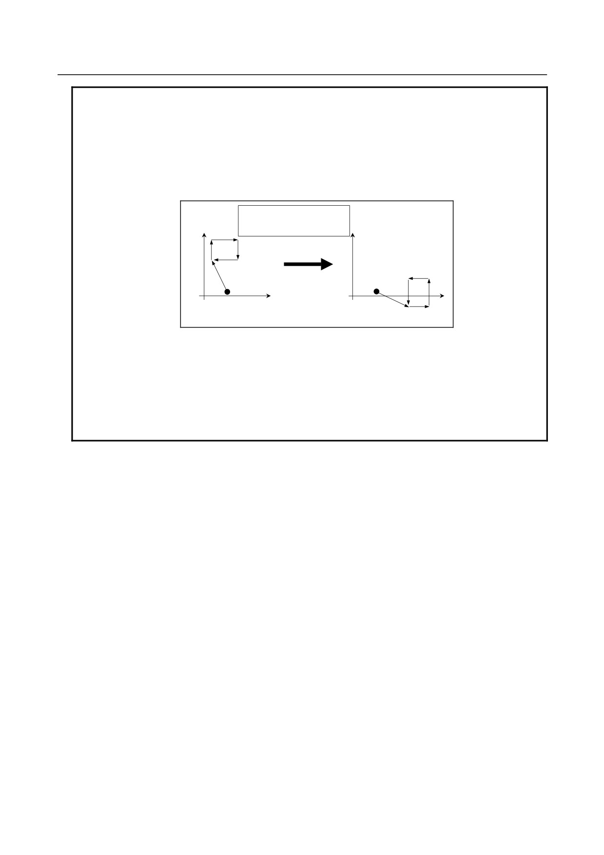
Switches X-axis command to Y-axis command.
Y
Y
Switches Y-axis command to X-axis command.
Switches Z-axis command to Z-axis command.
X
X
Programmed coordinates
Coordinates where workpiece is set
Explanation
・Axis switching No.
Six types of axis switching are possible as indicated below. The program addresses X, Y, and Z in each
type of axis switching correspond to the actually specified axes x, y, and z.
Programmed address
Axis switching No.
X
Y
Z
0
x
y
z
1
x
z
y
2
y
x
z
3
y
z
x
4
z
x
y
5
z
y
x
The axis switching number 0 means that axis switching is not performed.
・Axis switching specification method
(1) Specification based on the setting data
In the setting data (No. 10371), set an axis switching number (0 to 5).
(2) Specification based on programming
Specify programmable parameter input (G10L52) and set an axis switching number (0 to 5) in the
setting data (No. 10371).
(3) Specification using the switch on the machine operator's panel
For the method of specification, refer to the manual issued by the machine tool builder.
The table below indicates the relationship between specification (including programming) based on
setting data and specification using the switch on the machine operator's panel.
Setting of setting data
Setting of switch on machine
Valid setting
(No. 10371)
operator's panel
1
0
0
Axis switching is disabled.
2
1 to 5
0
Setting data
3
0
1 to 5
Switch on machine operator's panel
- 336 -
B-64484EN-2/02
PROGRAMMING
9.GAS CUTTING MACHINE
Setting of setting data
Setting of switch on machine
Valid setting
(No. 10371)
operator's panel
4
1 to 5
1 to 5
Switch on machine operator's panel
When axis switching is not performed, set both of the setting data and the switch on the machine
operator's panel to 0.
・Cases where axis switching is disabled
Axis switching is disabled when the commands below are specified.
(1) Manual operation
(2) Move command for moving to a particular machine position, command related to machine
coordinates, and command for coordinate system setting
(a) Automatic reference position return
G28, G30
(b) Floating reference position return
G30.1
(c) Return from reference position
G29
When bit 0 (RPC) of parameter No. 10370 is set to 1, axis switching is applied to the G29
command.
(d) Stored stroke check
G22, G23
(e) Coordinate system setting
G92, G68.2, G52
(f) Offset value setting
G10
(g) Dwell
G04
(h) Machine coordinate positioning
G53
(3) Real time custom macro
Example
When a command for axis switching is specified, the command is executed by performing program
interpretation in such a way that an address change is made according to the axis switching number.
Example) When axis switching No. = 4 is specified:
Specified command
:
G00 X100.0 Y200.0 Z300.0;
Axis switching command interpretation
:
G00 X200.0 Y300.0 Z100.0;
- 337 -
9.GAS CUTTING MACHINE
PROGRAMMING
B-64484EN-2/02
NOTE
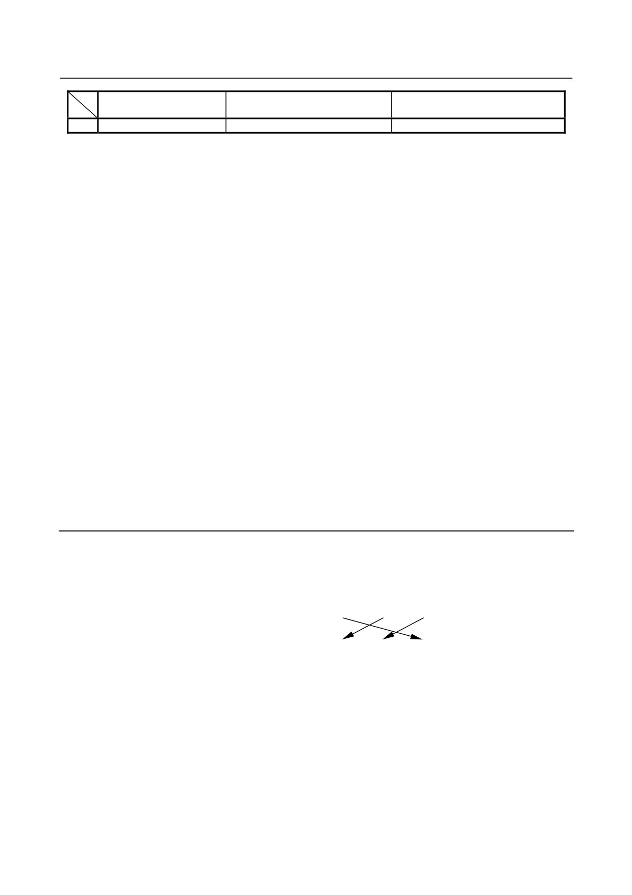
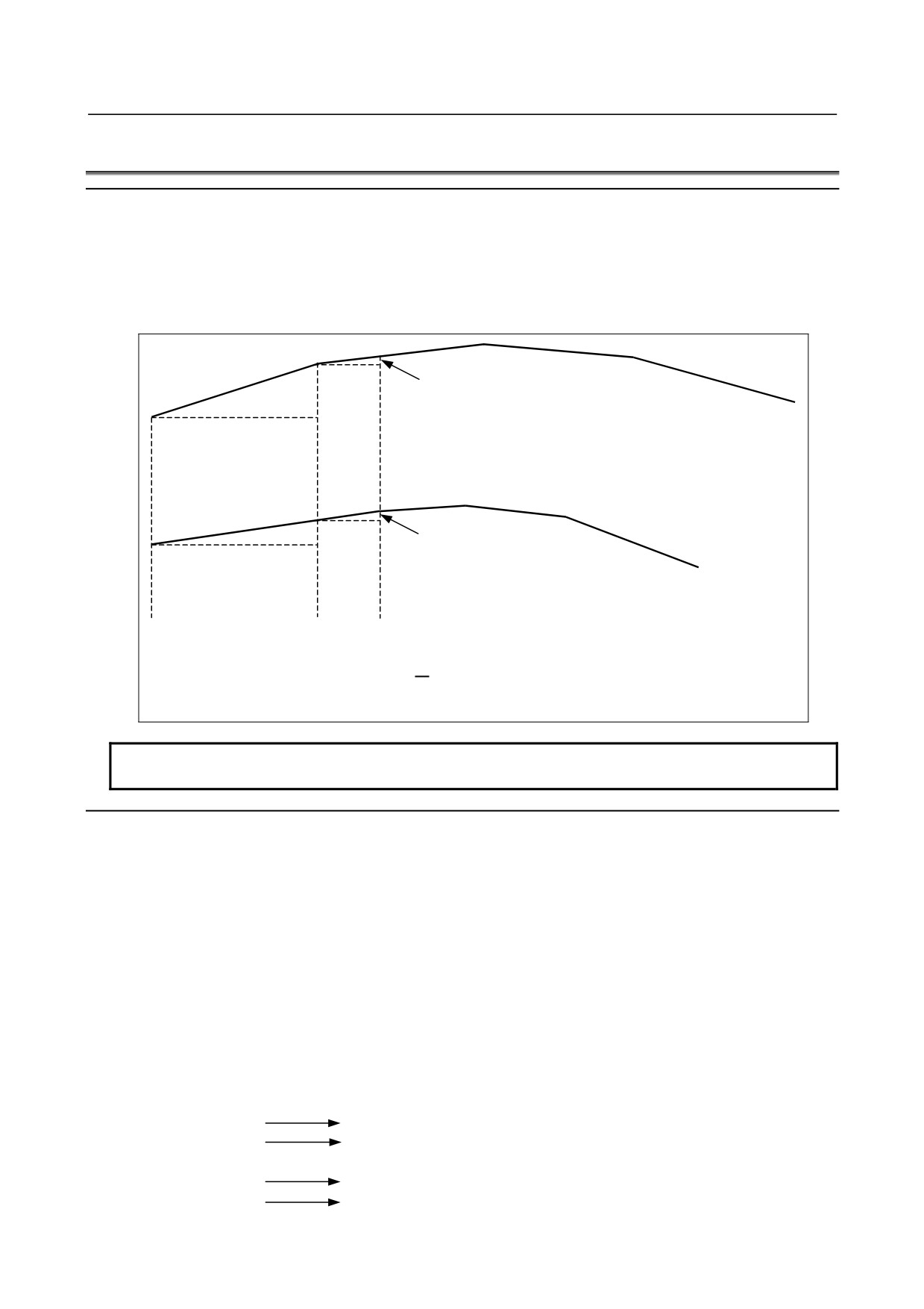
1 When the same program is used by axis switching, for example, the amount and
direction of movement are changed by axis switching, depending on the start
position and whether incremental or absolute programming is used.
(Example)
When the same start position is used but the direction of movement in
incremental programming is changed by axis switching
Switches X-axis command to Y-axis command.
Switches Y-axis command to X-axis command.
Y
Y
Switches Z-axis command to Z-axis command.
Start position
Start position
Programmed coordinates
X
Coordinates after axis switching
X
2 The hole machining axis in a canned cycle and tool length compensation and the
axis to which tool length compensation is applied can be fixed at the Z-axis by
setting bits 1 (TLB) and 0 (TLC) of parameter No. 5001 and bit 0 (FXY) of
parameter No. 5101. Even in this case, however, if program address Z is
changed to the machine axis x or y by axis switching, the hole machining axis
and the axis to which tool length compensation is applied are also changed to x
or y.
- 338 -
B-64484EN-2/02
PROGRAMMING
9.GAS CUTTING MACHINE
9.5
GENTLE CURVE CUTTING
Overview
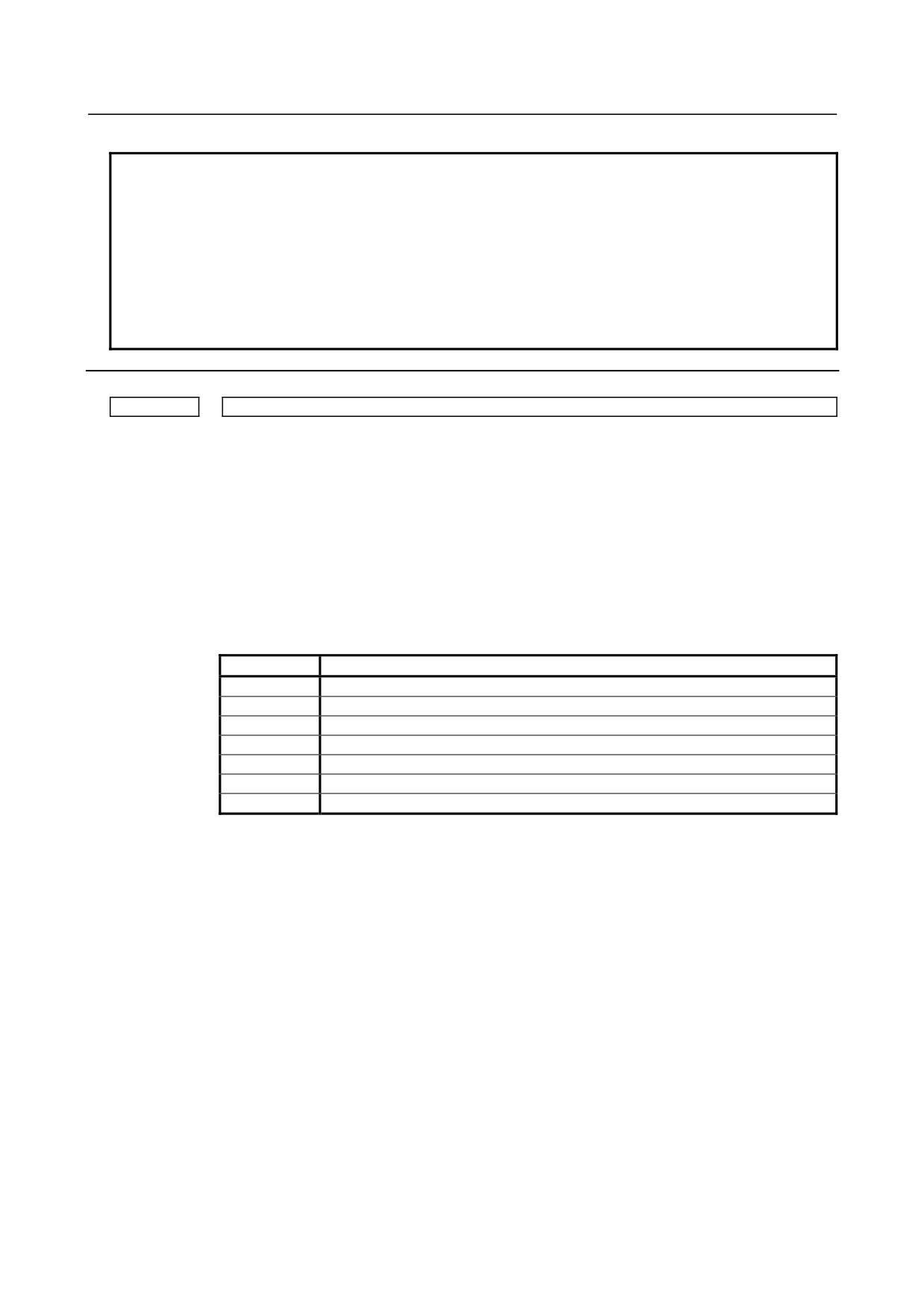
If the V-axis is added as an axis parallel with the Y-axis, the V-axis is treated as an axis parallel with the
Y-axis in the gentle curve cutting cancel mode (G13), and a command for the Y-axis alone is assumed to
be specified for the V-axis as well and enables movement also on the V-axis.
In the gentle curve cutting mode (G12), a command for the Y-axis is valid for the Y-axis alone, and a
command for the V-axis is valid for the V-axis alone.
x2
y2
y1
x1
v1
x2
v2
x1
G12 ;
G01 Xx1 Yy1 Vv1 F
;
Xx2 Yy2 Vv2 ;
NOTE
Be sure to specify G12 or G13 in a block specifying no other commands.
Explanation
If the V-axis is added as an axis parallel with the Y-axis, the V-axis is treated as an axis parallel with the
Y-axis in the gentle curve cutting cancel mode (G13), and a command for the Y-axis alone is assumed to
be specified for the V-axis as well and enables movement also on the V-axis. This means that the setting
of an axis parallel with the Y-axis is equivalent to the specification of the same axis name as the Y-axis.
However, the V-axis is treated as a slave of the Y-axis, so that no command may be specified for the
V-axis. If a command is specified for the V-axis, the alarm PS009, “IMPROPER NC-ADDRESS” is
issued. For details of a parallel axis, see the item of parallel axis control.
In the gentle curve cutting mode (G12), a command for the Y-axis is valid for the Y-axis alone, and a
command for the V-axis is valid for the V-axis alone.
G13;
Gentle curve cutting mode cancel
G12;
Gentle curve cutting mode
<Sample program>
Y move amount V move amount
G13;
G91 Y1000.0;
1000
1000
Y500.0;
500
500
G12;
Y35.0V50.0;
35
50
Y40.0V120.0;
40
120
- 339 -
9.GAS CUTTING MACHINE
PROGRAMMING
B-64484EN-2/02
NOTE
1 Be sure to specify G13 or G12 in a block specifying no other commands.
2 Ensure that the axis number of the basic axis is smaller than the axis number of
a parallel axis. Otherwise, no operation is enabled on the V-axis in the G13
mode.
3 If a command is specified for the V-axis in the G13 mode, the alarm PS0009,
“IMPROPER NC-ADDRESS” is issued.
4 In the G12 mode, do not specify circular interpolation (G02/G03).
5 In the G12 mode, be sure to set the G40 (cutter compensation cancel) mode.
Parameter
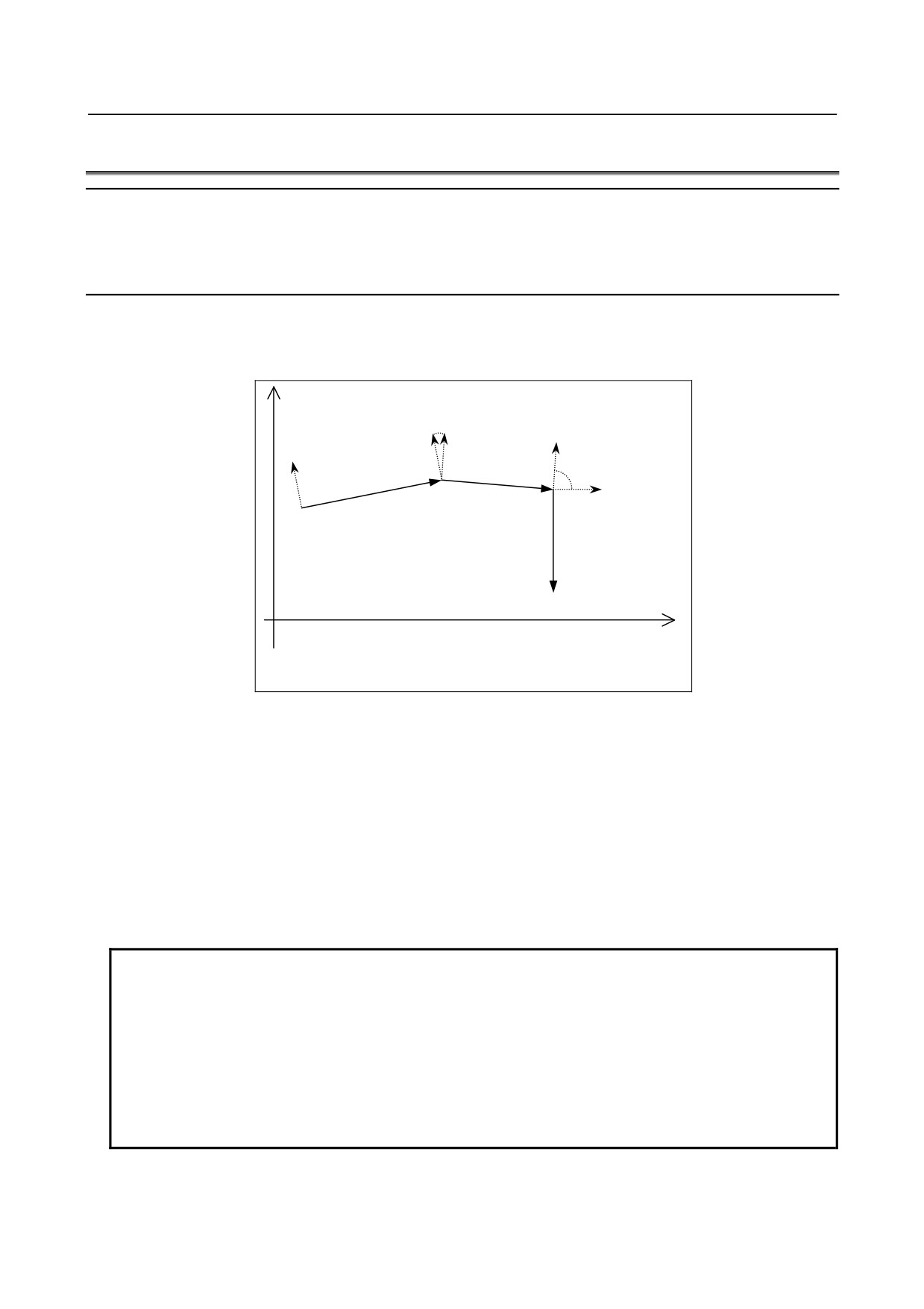
1022
Setting of each axis in the basic coordinate system
[Input type] Parameter input
[Data type] Byte axis
[Valid data range] 0 to 7
To determine a plane for circular interpolation, cutter compensation, and so forth (G17:
Xp-Yp plane, G18: Zp-Xp plane, G19: Yp-Zp plane) and a
3-dimensional tool
compensation space (XpYpZp), specify which of the basic three axes (X, Y, and Z) is
used for each control axis, or a parallel axis of which basic axis is used for each control
axis.
A basic axis (X, Y, or Z) can be specified only for one control axis.
Two or more control axes can be set as parallel axes for the same basic axis.
Setting
Meaning
0
Rotation axis (Neither the basic three axes nor a parallel axis)
1
X axis of the basic three axes
2
Y axis of the basic three axes
3
Z axis of the basic three axes
5
Axis parallel to the X axis
6
Axis parallel to the Y axis
7
Axis parallel to the Z axis
- 340 -
B-64484EN-2/02
PROGRAMMING
9.GAS CUTTING MACHINE
9.6
GENTLE NORMAL DIRECTION CONTROL
Overview
Gentle normal direction control enables movement on a rotary axis (C-axis) under normal direction
control simultaneously with movement on a linear axis (X/Y-axis). This makes the function applicable to
a gas cutting machine.
Explanation
Gentle normal direction control executes C-axis rotation and X/Y-axis movement at the same time when
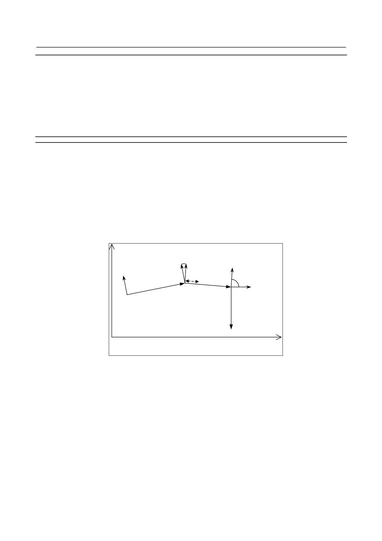
the C-axis rotation angle generated by normal direction control is less than the value of parameter No.
5485.
Y
T1
T2
N2
N1
N3
α: Angle set in parameter No. 5485
X
T1: Rotation angle from N1 to N2 (T1<α)
T2: Rotation angle from N2 to N3 (T2≧α)
Fig. 9.6 (a)
As shown in the Fig. 9.6 (a), when movement in the order of N1, N2, and N3 is specified:
1)
From N1 to N2, because T1 is less than α, the C-axis rotates angle T1 together with the movement of
the X- and Y-axes indicated by N2.
In this case, the movement distance of the C-axis is not included in calculation and the speed on the
XY plane is specified by F. (normal direction control)
2)
From N2 to N3, because T2 is equal to or greater than α, the C-axis rotates angle T2 before
movement of the X- and Y-axes in N3.(gentle normal direction control)
When the angle formed by a line and an arc or the angle formed between arcs is less than the angle set in
parameter No. 5485, the C-axis rotates with the movement of the X- and Y-axes as in the angle formed
between lines.
NOTE
1 When C-axis rotation included in an X/Y-axis move block is performed at the
same time, actual cutting feedrate display in linear interpolation (cutting) mode
shows the feedrate obtained from the following equation:
F’ = F×√(X2+Y2+C2)/√(X2+Y2)
2 The C-axis moves in response to X/Y-axis movement. If the C-axis feedrate
exceeds the maximum cutting speed or rapid traverse rate, however, the C-axis
feedrate is clamped at the maximum cutting speed or rapid traverse rate. The
X/Y-axis feedrate may therefore be different from the specified feedrate.
- 341 -
9.GAS CUTTING MACHINE
PROGRAMMING
B-64484EN-2/02
Limitation
(1) The normal direction control function is required for this function to be used.
(2) If the number of controlled axes including the C-axis exceeds the maximum number of
simultaneously controlled axes, the option for "simultaneously controlled axes expansion" is
required.
(3) F1 digit code cannot be specified.
(4) Restrictions on normal direction control applies to this function as well.
9.6.1
Linear Distance Setting
Explanation
By setting parameter No. 5486 to a travel distance for a block to move until the rotation of a normal
direction axis is completed, the normal direction axis is controlled to start rotation simultaneously with
the command block and terminates it upon completion of movement over the parameter-specified
distance.
This function is valid when the conditions for executing gentle normal direction control for rotating the
normal direction axis simultaneously with the command block are satisfied.
Assuming parameter No. 5486 specifying "a", the normal direction axis rotates an angle of T1 when the
N2 block having started execution reaches distance "a".
When the travel distance of the N2 block is less than or equal to the setting of parameter No. 5486, the
normal direction axis moves that travel distance.
Y
T1
a
T2
N2
N1
N3
X
Fig. 9.6.1 (a)
・Conditions
All of the following conditions must be satisfied for execution of gentle normal direction control:
(1) Gentle normal direction control is valid. (Bit 0 of parameter No. 5484 is set to 1.)
(2) The travel distance of the command block is equal to or more than the setting of parameter No. 5483
maintaining the normal direction angle of the previous block.
(3) The rotation angle calculated under normal direction control is more than the setting of parameter
No. 5482 for rotation of the normal direction control axis.
(4) The rotation angle calculated under normal direction control is less than the setting of parameter No.
5485 for rotation under gentle normal direction control.
This function rotates the normal direction axis according to the travel distance specified by parameter No.
5486 when the travel distance of the command block is more than the setting of parameter No. 5486 while
the conditions for execution of gentle normal direction control are satisfied.
- 342 -
B-64484EN-2/02
PROGRAMMING
9.GAS CUTTING MACHINE
・Limitation
• This function is invalid when the command block contains an arc command, in which case a regular
type of gentle normal direction control is exercised.
• This function cannot be used in inverse time feed mode.
NOTE
1 The normal direction axis moves in response to X/Y-axis movement. If the
feedrate of the normal direction axis exceeds the maximum cutting speed or
rapid traverse rate, however, the feedrate of the normal direction axis is clamped
at the maximum cutting speed or rapid traverse rate. The X/Y-axis feedrate may
therefore be lower that the specified feedrate.
2 When this function is used in a positioning command block, in-position check is
performed before the command block moves the remaining distance after the
rotation of the normal direction axis is completed.
- 343 -
B-64484EN-2/02
OPERATION
1.SETTING AND DISPLAYING DATA
1 SETTING AND DISPLAYING DATA
Chapter 1, "SETTING AND DISPLAYING DATA", consists of the following sections:
1.1 SCREENS DISPLAYED BY FUNCTION KEY
..................................................................347
1.1.1 Setting and Displaying the Tool Compensation Value
347
1.1.2 Tool Length Measurement
352
1.1.3 Tool Length/Workpiece Origin Measurement
355
1.1.4 Setting and Displaying the Rotary Table Dynamic Fixture Offset
374
1.1.5 Input of Tool Offset Value Measured B
377
1.1.6 Spindle Unit Compensation, Nutating Rotary Head Tool Length Compensation
377
SCREENS DISPLAYED BY FUNCTION KEY
1.1
Press function key
to display or set tool compensation values and other data.
This section describes how to display or set the following data:
1.
Tool compensation value
2.
Tool length measurement
3.
Tool length/workpiece origin measurement
4.
Rotary table dynamic fixture offset
5.
Tool offset value
6.
Spindle unit compensation, nutating rotary head tool length compensation
1.1.1
Setting and Displaying the Tool Compensation Value
Tool offset values, tool length compensation values, and cutter compensation values are specified by D
codes or H codes in a program. Compensation values corresponding to D codes or H codes are displayed
or set on the screen.
Procedure for setting and displaying the tool compensation value (for 8.4/10.4-inch
display unit)
Procedure
1
Press function key
For the two-path control, select the path for which tool compensation values are to be displayed with
the tool post selection switch.
2
Press chapter selection soft key [OFFSET] or press function key
several times until the tool
compensation screen is displayed.
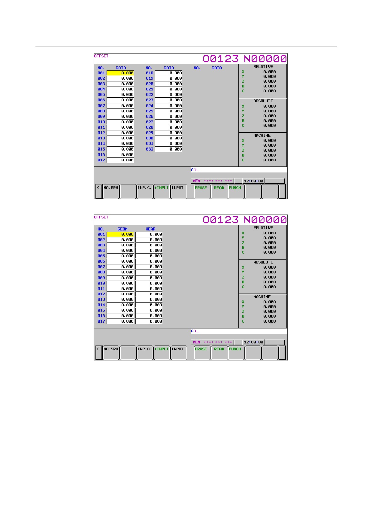
The screen varies according to the type of tool compensation memory.
- 347 -
1.SETTING AND DISPLAYING DATA OPERATION
B-64484EN-2/02
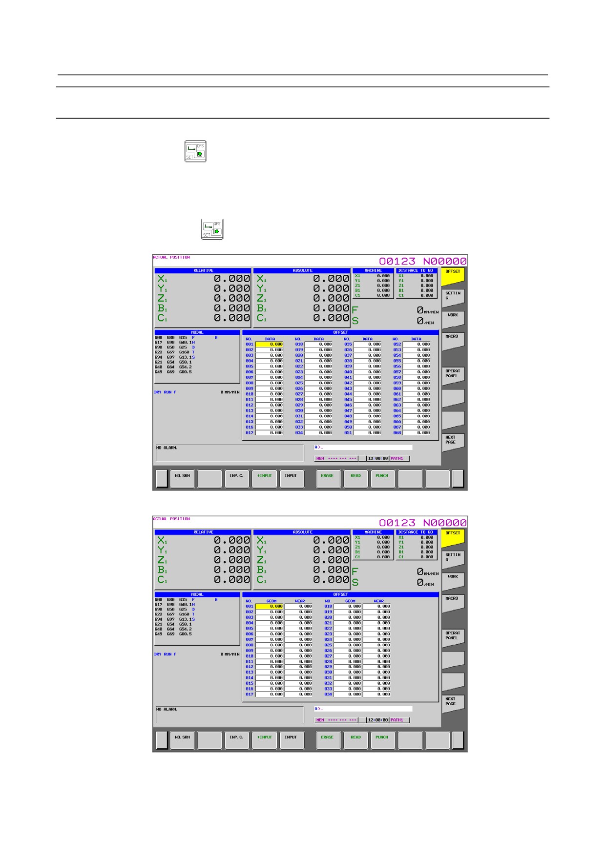
Fig. 1.1.1 (a) Tool compensation memory A (10.4-inch display unit)
Fig. 1.1.1 (b) Tool compensation memory B (10.4-inch display unit)
- 348 -
B-64484EN-2/02
OPERATION
1.SETTING AND DISPLAYING DATA
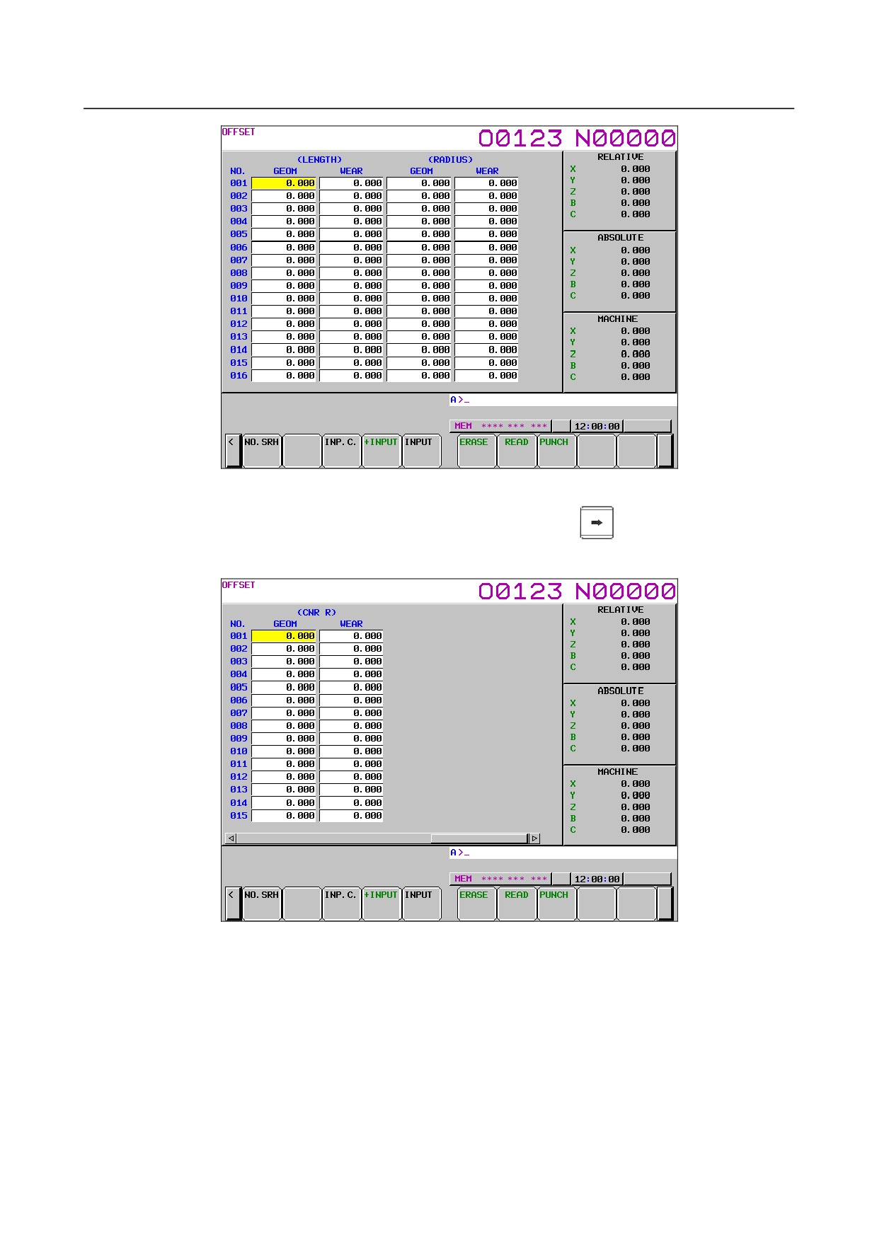
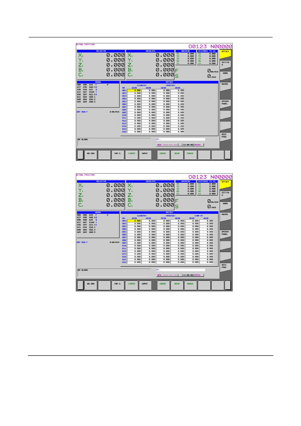
Fig. 1.1.1 (c) Tool compensation memory C (10.4-inch display unit)
If the cutting point command option is enabled, press the MDI key
several times on the tool
compensation memory C screen, the corner R offset setting screen is displayed.
Fig. 1.1.1 (d) Screen used for the cutting point command (10.4-inch display unit)
3
Move the cursor to the compensation value to be set or changed using page keys and cursor keys, or
enter the compensation number for the compensation value to be set or changed and press soft key
[NO.SRH].
4
To set a compensation value, enter a value and press soft key [INPUT].
To change the compensation value, enter a value to add to the current value (a negative value to
reduce the current value) and press soft key [+INPUT]. Or, enter a new value and press soft key
[INPUT].
- 349 -
1.SETTING AND DISPLAYING DATA OPERATION
B-64484EN-2/02
Procedure for setting and displaying the tool compensation value (for 15/19-inch
display unit)
Procedure
1
Press function key
For the two-path control, select the path for which tool compensation values are to be displayed with
the tool post selection switch.
2
Press the chapter selection key, in Fig.1.1.1 (e) Tool compensation memory A (15-inch display unit),
vertical soft key [OFFSET].
Or, press function key
several times until the tool compensation screen is displayed.
The screen varies according to the type of tool compensation memory.
Fig.1.1.1 (e) Tool compensation memory A (15-inch display unit)
Fig. 1.1.1 (f) Tool compensation memory B (15-inch display unit)
- 350 -
B-64484EN-2/02
OPERATION
1.SETTING AND DISPLAYING DATA
Fig. 1.1.1 (g) Tool compensation memory C (15-inch display unit)
Fig. 1.1.1 (h) Screen used for the cutting point command (15-inch display unit)
3
Move the cursor to the compensation value to be set or changed using page keys and cursor keys, or
enter the compensation number for the compensation value to be set or changed and press horizontal
soft key [NO.SRH].
4
To set a compensation value, enter a value and press horizontal soft key [INPUT].
To change the compensation value, enter a value to add to the current value (a negative value to
reduce the current value) and press horizontal soft key [+INPUT]. Or, enter a new value and press
horizontal soft key [INPUT].
Explanation
-
Decimal point input
A decimal point can be used when entering a compensation value.
- 351 -
1.SETTING AND DISPLAYING DATA OPERATION
B-64484EN-2/02
-
Other setting method
An external input/output device can be used to input or output a tool offset value. See Chapter III-8 in
OPERATOR’S MANUAL (Common to T/M). A tool length compensation value can be set by measuring
the tool length as described in the next subsection.
-
Tool compensation memory
There are tool compensation memories A, B, and C, which are classified as follows:
Tool compensation memory A
D codes and H codes are treated the same. Tool geometry compensation and tool wear compensation
are treated the same.
Tool compensation memory B
D codes and H codes are treated the same. Tool geometry compensation and tool wear compensation
are treated differently.
Tool compensation memory C
D codes and H codes are treated differently. Tool geometry compensation and tool wear
compensation are treated differently.
-
Disabling entry of compensation values
The entry of compensation values may be disabled by setting bit 0 (WOF) and bit 1 (GOF) of parameter
No.3290 (not applied to tool compensation memory A).
And then, the input of tool compensation values from the MDI can be inhibited for a specified range of
offset numbers. The first offset number for which the input of a value is inhibited is set in parameter No.
3294. The number of offset numbers, starting from the specified first number, for which the input of a
value is inhibited is set in parameter No. 3295.
Consecutive input values are set as follows:
1)
When compensation values are input consecutively from offset numbers for which the input of
values is enabled to offset numbers for which the input of values is inhibited, a warning is issued,
but the compensation values in the range of the offset numbers for which the input of values is
enabled are set.
2)
When compensation values are input consecutively from offset numbers for which the input of
values is inhibited to offset numbers for which the input of values is enabled, a warning is issued and
the compensation values are not set.
1.1.2
Tool Length Measurement
The length of the tool can be measured and registered as the tool length compensation value by moving
the reference tool and the tool to be measured until they touch the specified position on the machine.
The tool length can be measured along the X-, Y-, or Z-axis.
Procedure for tool length measurement (for 8.4/10.4-inch display unit)
Procedure
1
Use manual operation to move the reference tool until it touches the specified position on the
machine (or workpiece.)
2
Press function key
several times until the current position display screen with relative
coordinates is displayed.
- 352 -
B-64484EN-2/02
OPERATION
1.SETTING AND DISPLAYING DATA
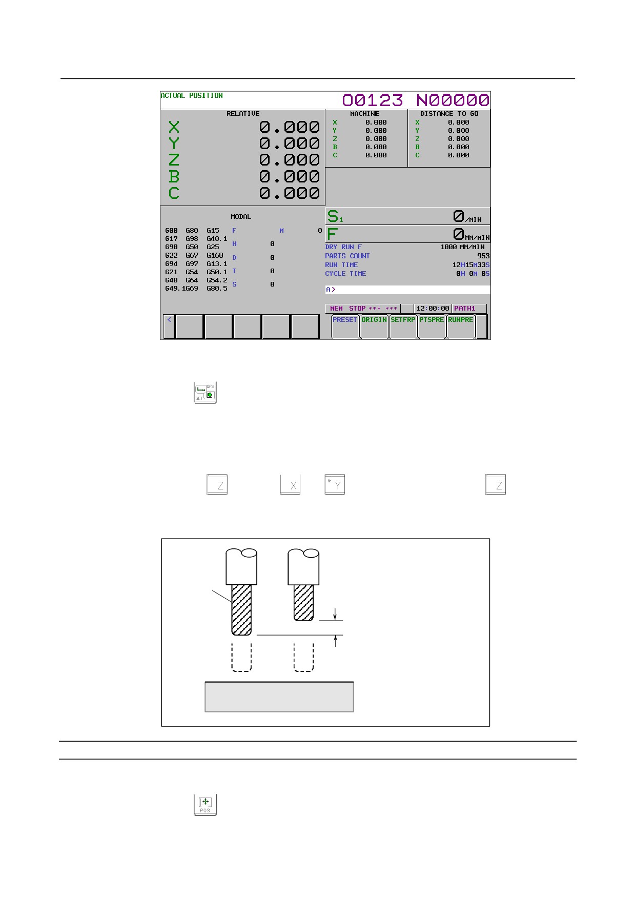
Fig. 1.1.2 (a) Current position display screen (10.4-inch display unit)
3
Reset the relative coordinate for the Z-axis to 0.
4
Press function key
several times until the tool compensation screen is displayed.
5
Use manual operation to move the tool to be measured until it touches the same specified position.
The difference between the length of the reference tool and the tool to be measured is displayed in
the relative coordinates on the screen.
6
Move the cursor to the compensation number for the target tool (the cursor can be moved in the
same way as for setting tool compensation values).
7
Press the address key
. If either
or
key is depressed instead of
key, the X or
Y axis relative coordinate value is input as an tool length compensation value.
8
Press the soft key [INP.C.]. The Z axis relative coordinate value is input and displayed as an tool
length compensation value.
Reference
tool
The difference is set as a tool
length offset value
A prefixed position
Procedure for tool length measurement (for 15/19-inch display unit)
1
Use manual operation to move the reference tool until it touches the specified position on the
machine (or workpiece.)
2
Press function key
to display the overall position display screen.
- 353 -
1.SETTING AND DISPLAYING DATA OPERATION
B-64484EN-2/02
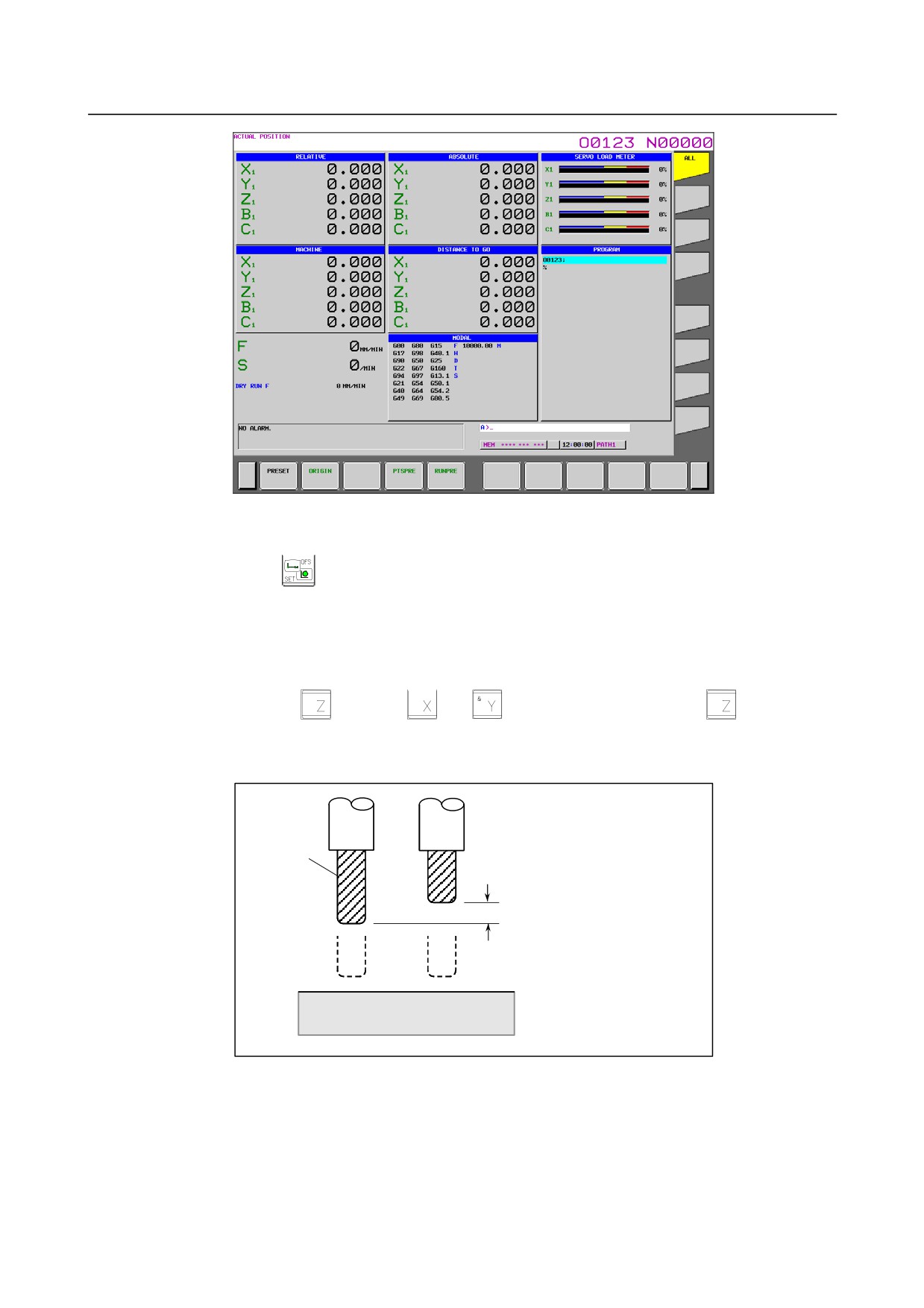
Fig. 1.1.2 (b) Current position display screen (15-inch display unit)
3
Reset the relative coordinate for the Z-axis to 0.
4
Press function key
several times until the tool compensation screen is displayed.
5
Use manual operation to move the tool to be measured until it touches the same specified position.
The difference between the length of the reference tool and the tool to be measured is displayed in
the relative coordinates on the screen.
6
Move the cursor to the compensation number for the target tool (the cursor can be moved in the
same way as for setting tool compensation values).
7
Press the address key
. If either
or
key is depressed instead of
key, the X or
Y axis relative coordinate value is input as an tool length compensation value.
8
Press the horizontal soft key [INP.C.]. The Z axis relative coordinate value is input and displayed as
an tool length compensation value.
Reference
tool
The difference is set as a tool
length offset value
A prefixed position
- 354 -