FANUC Series 30i-MODEL B, 31i-MODEL B, 32i-MODEL B. For Machining Center System. OPERATOR'S MANUAL - page 10
6.COMPENSATION FUNCTION
PROGRAMMING
B-64484EN-2/02
Limitation
-
Manual operation that cannot change an active offset value
In a mode other than the manual handle feed mode/incremental feed mode/jog feed mode, no active offset
value can be changed.
Moreover, no active offset value can be changed in the manual reference position return mode.
Even in the modes mentioned above, do not change an active offset value in the following operations:
•
3-dimensional manual feed
•
Manual numerical command
•
PMC axis control
-
Axis that disables an active offset value from being changed
With a rotation axis, no tool length compensation/cutter compensation value can be changed using this
function.
6.14 ROTARY TABLE DYNAMIC FIXTURE OFFSET
Overview
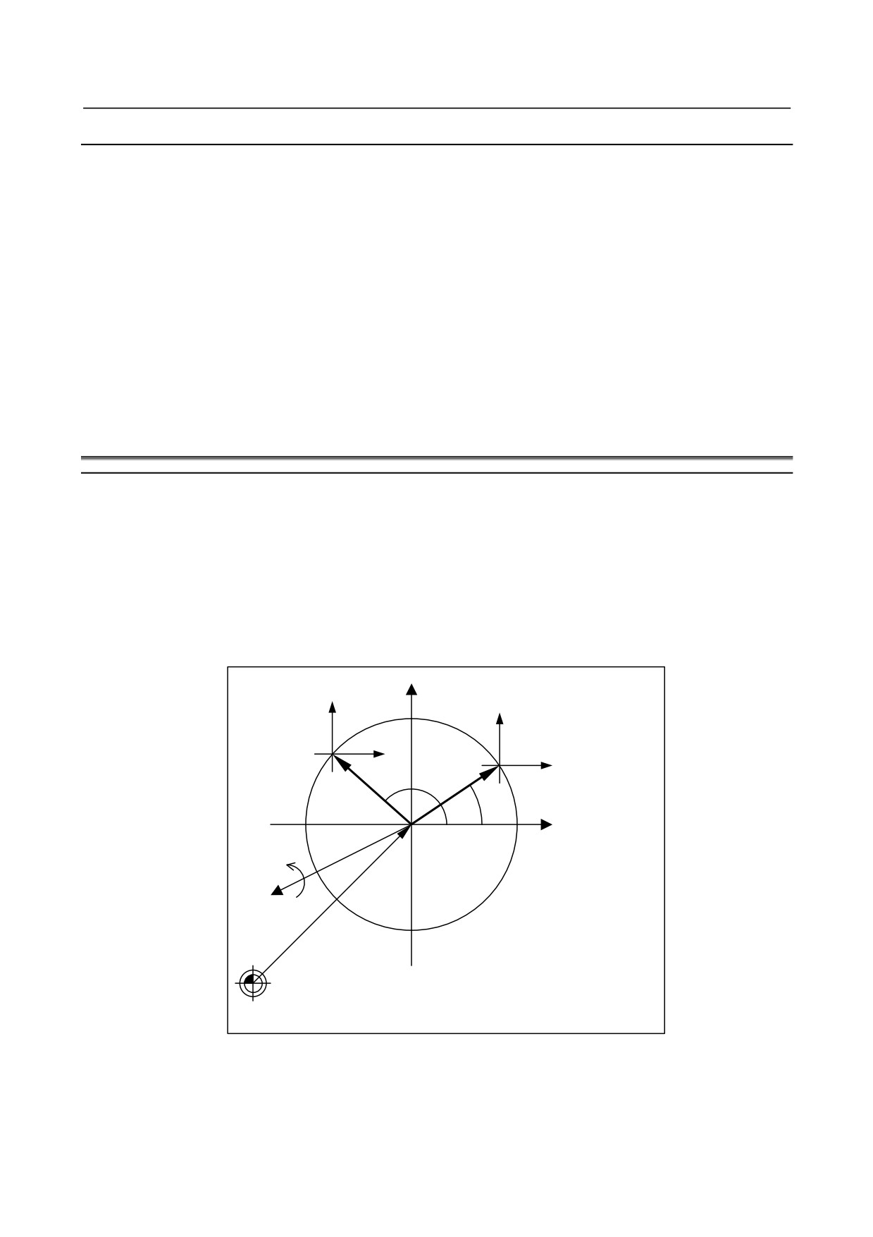
The rotary table dynamic fixture offset function saves the operator the trouble of resetting the workpiece
coordinate system when the rotary table rotates before cutting is started. With this function the operator
simply sets the position of a workpiece placed at a certain position on the rotary table as a reference
fixture offset. If the rotary table rotates, the system automatically obtains a current fixture offset from the
angular displacement of the rotary table and creates a suitable workpiece coordinate system. After the
reference fixture offset is set, the workpiece coordinate system is prepared dynamically, wherever the
rotary table is located.
The zero point of the workpiece coordinate system is obtained by adding the fixture offset to the offset
from the workpiece reference point.
Y
Y
Y
X
X
F0
F
θ
θ
0
X
Rotation axis
center
C
Z
W
W : Workpiece origin offset value
θ0
: Reference angle
F0 : Reference fixture offset value
Machine
system origin
θ
: Rotation axis angle
F
: Fixture offset value
Fig. 6.14 (a) Fixture offset
- 262 -
B-64484EN-2/02
PROGRAMMING
6.COMPENSATION FUNCTION
Format
-
Fixture offset command
G54.2 Pn ;
n : Reference fixture offset value number (1 to 8)
-
Fixture offset cancel command
G54.2 P0 ;
NOTE
1 In the G54.2 mode, a change made to the setting of parameter or to the
reference fixture offset becomes effective when the next block is buffered.
2 It depends on the current continuous-state code of the 01 group whether a
change in the fixture offset vector causes a movement. If the system is in a
mode other than the G00 or G01 mode (G02, G03, etc.), the movement is made
temporarily in the G01 mode.
3 When a rotation axis that is related to fixture offset, command is specified in the
G54.2 mode, the vector is calculated with the coordinate value of the end of the
block and the movement is performed to the command position on the
coordinate system pointed by the vector .
4 In calculation of the fixture offset, the coordinate of the rotation axis on the
workpiece coordinate system is used. If a tool offset or another offset is applied,
the coordinate before the offset is used.
If mirror image or scaling is performed, the coordinate before the operation is
used.
Explanation
-
Fixture offset command
When a command G54.2Pn is specified, a fixture offset value is calculated from the current rotation angle
and the data specified with n, and enable the fixture offset value.
If n = 0, the fixture offset value is disabled.
-
When a move command is specified for a rotation axis in G54.2 mode
When a command to move the tool about a rotation axis involved with a fixture offset is specified in the
G54.2 mode, the coordinates about the rotation axis at the end of the block are used to calculate a vector.
The tools moved to the specified position on the workpiece coordinate system that is indicated by the
vector.
-
Operation at reset
Whether to cancel the fixture offset at a reset depends on the settings of bit 6 (CLR) of parameter No.
3402 and of bit 7 (C23) of parameter No. 3408.
When CLR is set to 0 or CLR and C23 are set to 1, the vector before the reset is saved.
When CLR is set to 1 and C23 is set to 0, the vector is cleared. The machine does not move by the cleared
vector regardless of the setting of bit 0 (FTP) of parameter No. 7570, however.
-
Data setting
(1) Setting a group of three parameters which specify one rotation axis and two linear axes constituting
the plane of rotation (Parameters Nos. 7580 to 7588).
In each group, specify the number of the rotation axis as the first parameter and the numbers of the
linear axes as the second and third parameters. The rotation in the normal direction about the rotation
axis must agree with the rotation from the positive side of the linear axis set as the second parameter
to the positive side of the linear axis set as the third parameter.
- 263 -
6.COMPENSATION FUNCTION
PROGRAMMING
B-64484EN-2/02
Example)
Suppose that a machine has four axes, X, Y, Z, and C. The X-, Y-, and Z-axes form a
right-handed coordinate system. The C-axis is a rotation axis. When viewed from the positive
side of the Z-axis, a rotation in the normal direction about the C-axis is treated as the
counterclockwise rotation around the Z-axis.
For this machine, specify the parameters as follows
First parameter : 4 (C-axis)
Second parameter : 1 (X-axis)
Third parameter : 2 (Y-axis)
Up to three groups of parameters can be set. In calculation of the fixture offset, the data of the
rotation axis specified in the first group is calculated first. Then, the data of the second and third
groups are calculated.
If a machine has two or more rotation axes and the plane of rotation depends on the rotation about
another rotation axis, the plane of rotation is set when the angular displacement about the rotation
axis is 0.
(2)
Setting the reference angle of the rotation axis and the corresponding reference fixture offset
Set the reference angle of the rotation axis and the fixture offset that corresponds to the reference
angle.
Set the data on the fixture offset screen. Eight groups of data items can be specified.
(3)
Setting a parameter for enabling or disabling the fixture offset of each axis
(bit 0 (FAX) of parameter No. 7575)
For the axis for which the fixture offset is enabled, set the parameter to 1. This need not be specified
for a rotation axis.
(4)
Setting the type of fixture offset (bit 0 (FTP) of parameter No. 7570)
Specify whether to cause a movement according to the increment or decrement of the fixture offset
vector when the vector changes (when G54.2 is specified or when a rotation axis movement occurs
in the G54.2 mode).
When 0 is set, the movement is made. (The current position on the workpiece coordinate system
does not change. The position on the machine coordinate system changes.)
When 1 is set, the movement is not made. (The current position on the workpiece coordinate system
changes. The position on the machine coordinate system does not change.)
-
Input/output of fixture offset
The data can be programmed and can be input from and output to external equipment, as described
below:
(1) Setting the reference fixture offset by G10
G10 L21 Pn P ;
n: Reference fixture offset number
P: Reference fixture offset or reference angle of each axis
With this command, a reference fixture offset or reference angle can be programmed.
If the command is executed in the G90 mode, the specified value is set directly. If the command is
executed in the G91 mode, the sum of the specified value and the previous value is set.
(2) Reading/writing based on a custom macro system variable
The following system variable number can be used to read and write a reference fixture offset value
or a reference angle. However, it is impossible to write to a system variable area (5500 to 5508) if n
= 0.
System variable number = 5500 + 20 * n + m
n: Fixture offset number (1 to 8)
(The current offset is used if n = 0.)
m: Axis number (1 to number of controlled axes)
- 264 -
B-64484EN-2/02
PROGRAMMING
6.COMPENSATION FUNCTION
NOTE
The custom macro function is needed.
(3) Output to external units
Selecting [OUTPUT] on the fixture offset screen enables outputting to external units such as a
floppy cassette and memory card via RS-232-C.
Output data is in the G10 format with no program number.
NOTE
The reader/punch interface function is needed.
(4) Input from an external units.
Selecting [NPUT] on the program edit screen, the data can be input from a Floppy Cassette and
memory card via RS-232-C.
(Amount of the Fixture offset is set by inputting as NC program, and executing it.)
NOTE
The reader/punch interface function is needed.
-
Calculating a Fixture Offset values
(1) Relationship between the rotation axes and linear axes
First group
: 4 (B-axis) , 3 (Z-axis) , 1 (X-axis)
Second group : 5 (C-axis) , 1 (X-axis) , 2 (Y-axis)
Third group
: 0
,
0
,
0
(2) Reference angle and reference fixture offset
X : F0X
Y : F0Y
Z : F0Z
B : θ0
C : φ0
If the above data is set up, the method of calculating fixture offset value is as follows:
O
: Rotary table center
W
: Workpiece origin offset value
F0
:Fixture offset value when B=θ0, C=φ0
FA
:Fixture offset value (FAX,FAY,FAZ) when B=0, C=0
F
: Fixture offset value (FX,FY,FZ) when B=θ, C=φ
Then, the following expression is used for fixture offset calculation.
⎡F
AX
⎤
⎡
cos
(
−θ
0
)
0
sin
(
−θ
0
)
⎤⎡cos
(
−φ
0
)
−sin
(
−φ
0
)
0⎤⎡F
0X
⎤
⎢
⎥
⎢
⎥⎢
⎥⎢
⎥
F
AY
=
0
1
0
sin
(
−φ
0
)
cos
(
−φ
0
)
0
F
0Y
⎢
⎥
⎢
⎥⎢
⎥⎢
⎥
⎢F
AZ
⎥
⎢−sin
(
−θ
0
)
0
cos
(
−θ
0
)
⎥⎢
0
0
1⎥⎢F
0Z
⎥
⎣
⎦
⎣
⎦⎣
⎦⎣
⎦
⎡F
X
⎤
⎡cos
(
φ
)
−sin
(
φ
)
0⎤⎡
cos
(
θ
)
0
sin
(
θ
)
⎤⎡F
AX
⎤
⎢
⎥
⎢
⎥⎢
⎥⎢
⎥
F
Y
=
sin
(
φ
)
cos
(
φ
)
0
0
1
0
F
AY
⎢
⎥
⎢
⎥⎢
⎥⎢
⎥
⎢F
Z
⎥
⎢
0
0
1⎥⎢−sin
(
θ
)
0
cos
(
θ
)
⎥⎢F
AZ
⎥
⎣
⎦
⎣
⎦⎣
⎦⎣
⎦
-
If manual intervention is made on the rotation axis
When the automatic operation is stopped by the SBK stop or similar in the G54.2 mode, and a manual
movement is made about the rotation axis, the vector of the fixture offset does not change. When a
rotation axis command is specified in automatic operation or in MDI operation or When G54.2 is
specified, the vector is calculated.
- 265 -
6.COMPENSATION FUNCTION
PROGRAMMING
B-64484EN-2/02
When manual intervention is performed with bit 3 (CFA) of parameter No. 7570 =0 and in the manual
absolute switch is set on and then a rotation axis command is specified in the incremental (G91) mode,
the vector is calculated using the coordinates which do not reflect the amount of manual intervention.
Example)
N1 G90 G00 C10.0 ;
N2 G54.2 P1 ;
After executing the program, perform manual intervention with the manual absolute switch is set to
on. Then, movement of +20.0 about the C-axis.
After restart
N3 G91 C30.0 ;
is specified, the coordinate value of C-axis is 60.0 in the workpiece coordinate system.
In the fixture offset calculation, however, the coordinate value of C-axis is considered as 40.0.
If, in N3, the bit 3 (CFA) of parameter No. 7570 is 1 and bit 1 (ABS) of parameter No. 7001 is 1, the
coordinate value of C-axis is considered as 10.0 (30.0 - 20.0) as specified when the calculation is
performed.
Limitation
-
Command for suppressing fixture offset calculation
If the following commands are specified for the rotation axis in the G54.2 mode, the fixture offset vector
is not calculated:
Command related to the machine coordinate system: G53
Command specifying a change of the workpiece coordinate system: G54 to G59, G54.1, G92, and G52
Command specifying a return to the reference position: G27, G28, G29, G30, G30.1
-
Rotation axis used for fixture offset
The rotation axis used for polar coordinate interpolation (G12.1) cannot be set as the rotation axis for the
fixture offset.
-
Rotation axis roll over
When using the rotary axis roll over function, always specify 360 degrees for the amount of travel per
revolution of the rotation axis.
-
Functions that cannot be specified
In the G54.2 mode, the functions listed below cannot be specified.
Coordinate system rotation function
Figure copying function
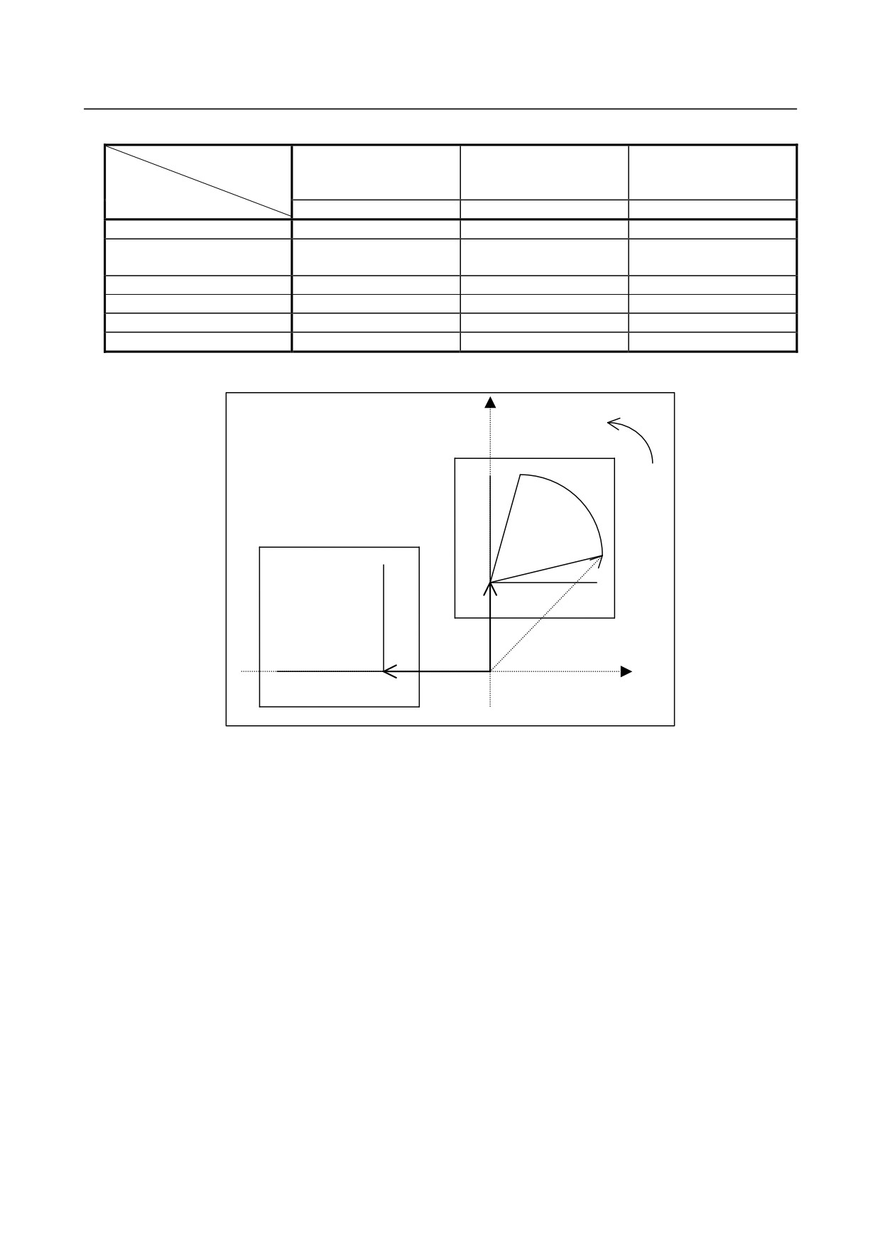
Example
Parameter
No. 7580=4 (C-axis)
No. 7581=1 (X-axis)
No. 7582=2 (Y-axis)
Nos. 7583 to 7588=0
No. 7575#0(X)=1 (The offset is valid for the X-axis.)
No. 7575#0(Y)=1 (The offset is valid for the Y-axis.)
No. 7570#0=0 (When No. 7570#0=1, the values in square brackets ([ ]) are calculated.)
Data of fixture offset 1 (n = 1)
C= 180.0 (reference angle)
X= -10.0
Y= 0.0
When these parameters and data are set, the machine operates as shown below :
- 266 -
B-64484EN-2/02
PROGRAMMING
6.COMPENSATION FUNCTION
Table 6.14 (a) Example of fixture offset
Coordinates
Position on the
Position on the
workpiece coordinate
machine coordinate
Fixture offset
system (ABSOLUTE)
system (MACHINE)
Program
X
Y
C
X
Y
C
X
Y
C
N1 G90 G00 X0 Y0 C90. ;
0.0
0.0
90.0
0.0
0.0
90.0
0.0
0.0
0.0
N2 G54.2 P1 ;
0.0
0.0
90.0
0.0
10.0
90.0
0.0
10.0
0.0
[0.0
-10.0
90.0]
[0.0
0.0
90.0]
[0.0
10.0
0.0]
N3 G01 X10. Y2. F100. ;
10.0
2.0
90.0
10.0
12.0
90.0
0.0
10.0
0.0
N4 G02 X2. Y10. R10. ;
2.0
10.0
90.0
2.0
20.0
90.0
0.0
10.0
0.0
N5 G01 X0 Y0 ;
0.0
0.0
90.0
0.0
10.0
90.0
0.0
10.0
0.0
…
The values enclosed in brackets ([ ]) apply when bit 0 (FTP) of parameter No. 7570 is set to 1.
Y
C
C=90°
N4
C=180°
N5
N3
N2
[N3]
X
Machine coordinate system
zero point
Fig. 6.14 (b) Example of fixture offset
When G54.2 P1 is specified in the N2 block, the fixture offset vector (X=0, Y=10.0) is calculated. The
vector is handled in the same way as the offset from the workpiece reference point. The current position
on the workpiece coordinate system is (X=0, Y=-10.0). If bit 0 (FTP) of parameter 7570 is set to 0, the
tool is moved according to the vector. The resultant position on the workpiece coordinate system is (X=0,
Y=0), the position before the command is specified.
- 267 -
6.COMPENSATION FUNCTION
PROGRAMMING
B-64484EN-2/02
6.15 TOOL AXIS DIRECTION TOOL LENGTH COMPENSATION
Overview
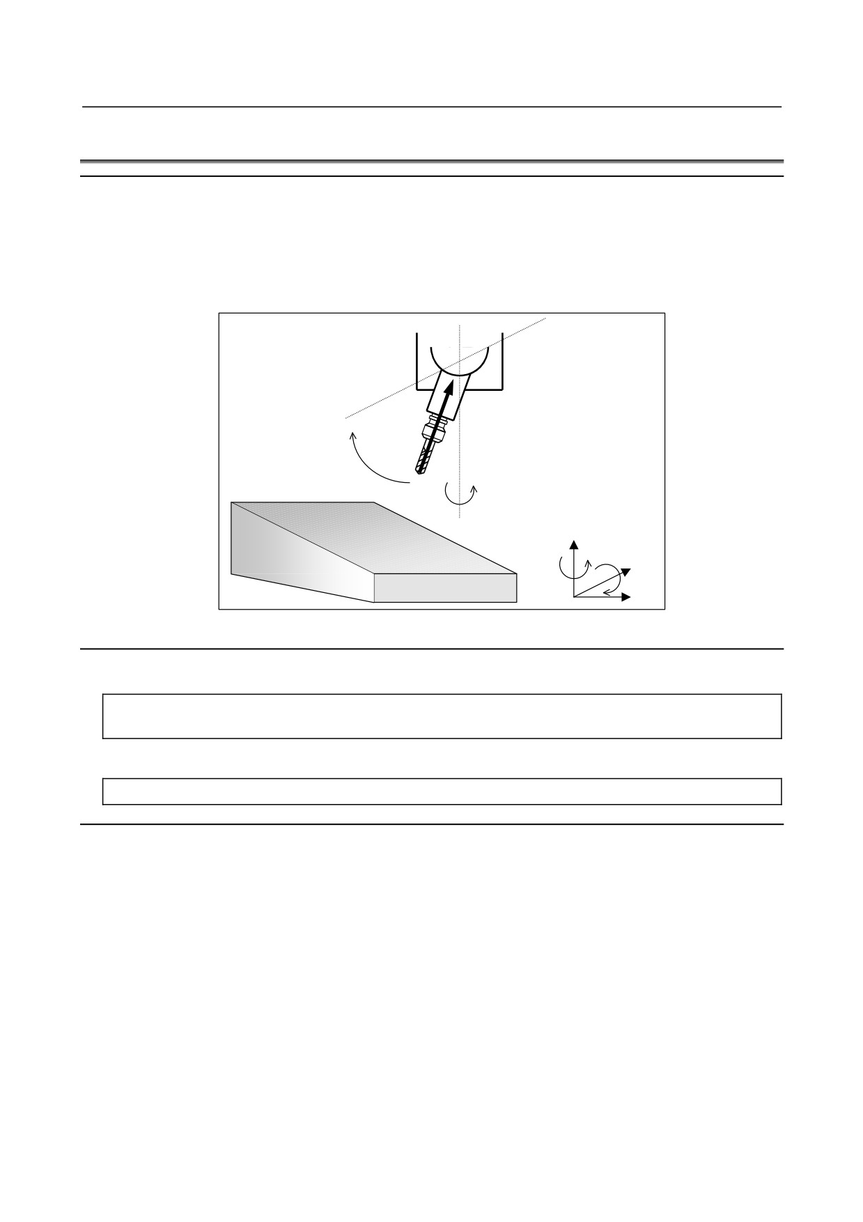
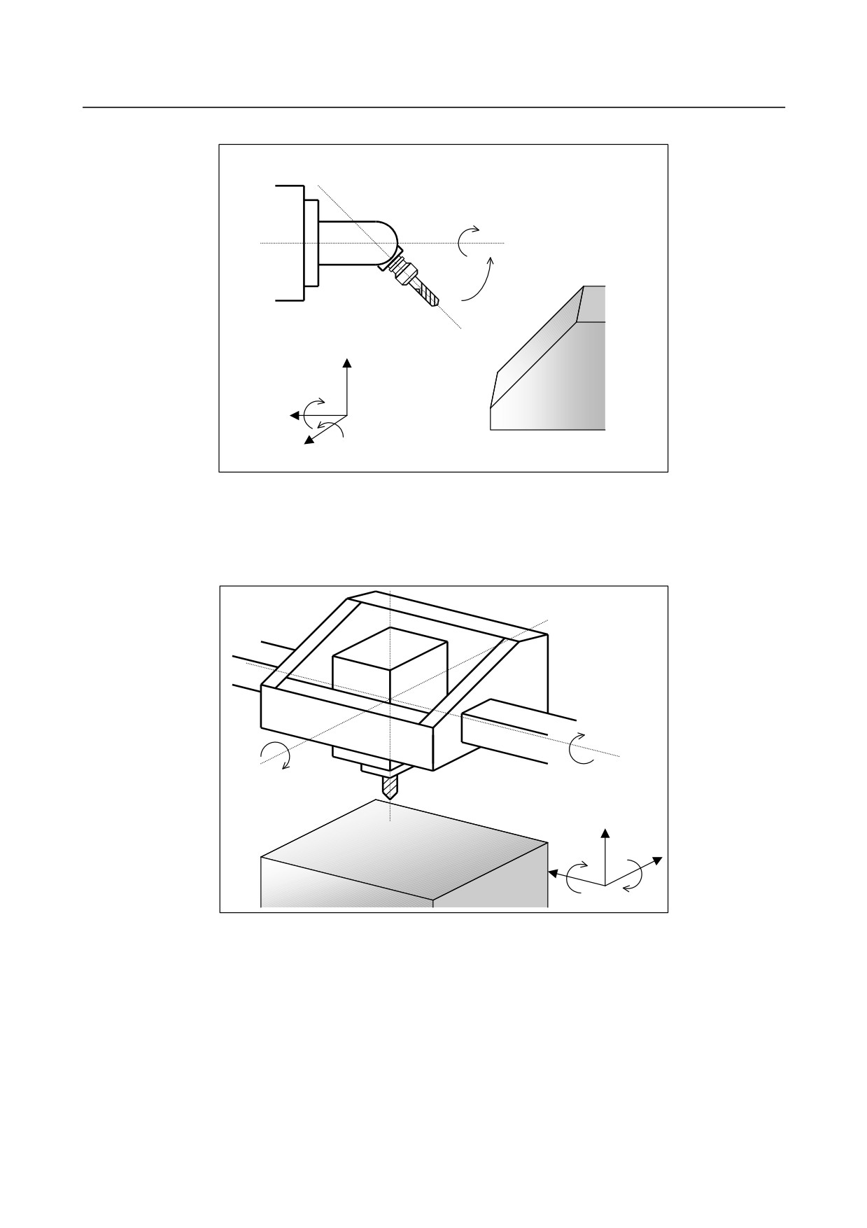
When a five-axis machine that has two axes for rotating the tool is used, tool length compensation can be
performed in a specified tool axis direction on a rotation axis. When a rotation axis is specified in tool
axis direction tool length compensation mode, tool length compensation is applied in a specified tool axis
direction on the rotation axis by the compensation value specified in the H code. That is, movement is
made along the three linear axes (Xp, Yp, Zp). Unless otherwise noted in the explanation of this function,
the two rotation axes are assumed to be the B-axis and C-axis.
Tool axis direction
B
C
Z
Workpiece
C
B
Y
X
Fig. 6.15 (a) Tool Axis Direction Tool Length Compensation
Format
-
Tool axis direction tool length compensation command
G43.1 Hn ;
n: Compensation number
-
Tool axis direction tool length compensation cancel command
G49 ;
Explanation
- Command for tool axis direction tool length compensation
The tool compensation vector changes as the offset value changes or movement is made on a rotation axis.
When the tool compensation vector changes, movement is made according to the change value along the
X-axis, Y-axis, and Z-axis.
When the command specifies movement on a rotation axis only, the position of the tool tip is the same
both before and after execution of the command. (During rotation axis movement, however, the tool tip
moves.)
- Examples of machine configuration and rotation axis calculation formats
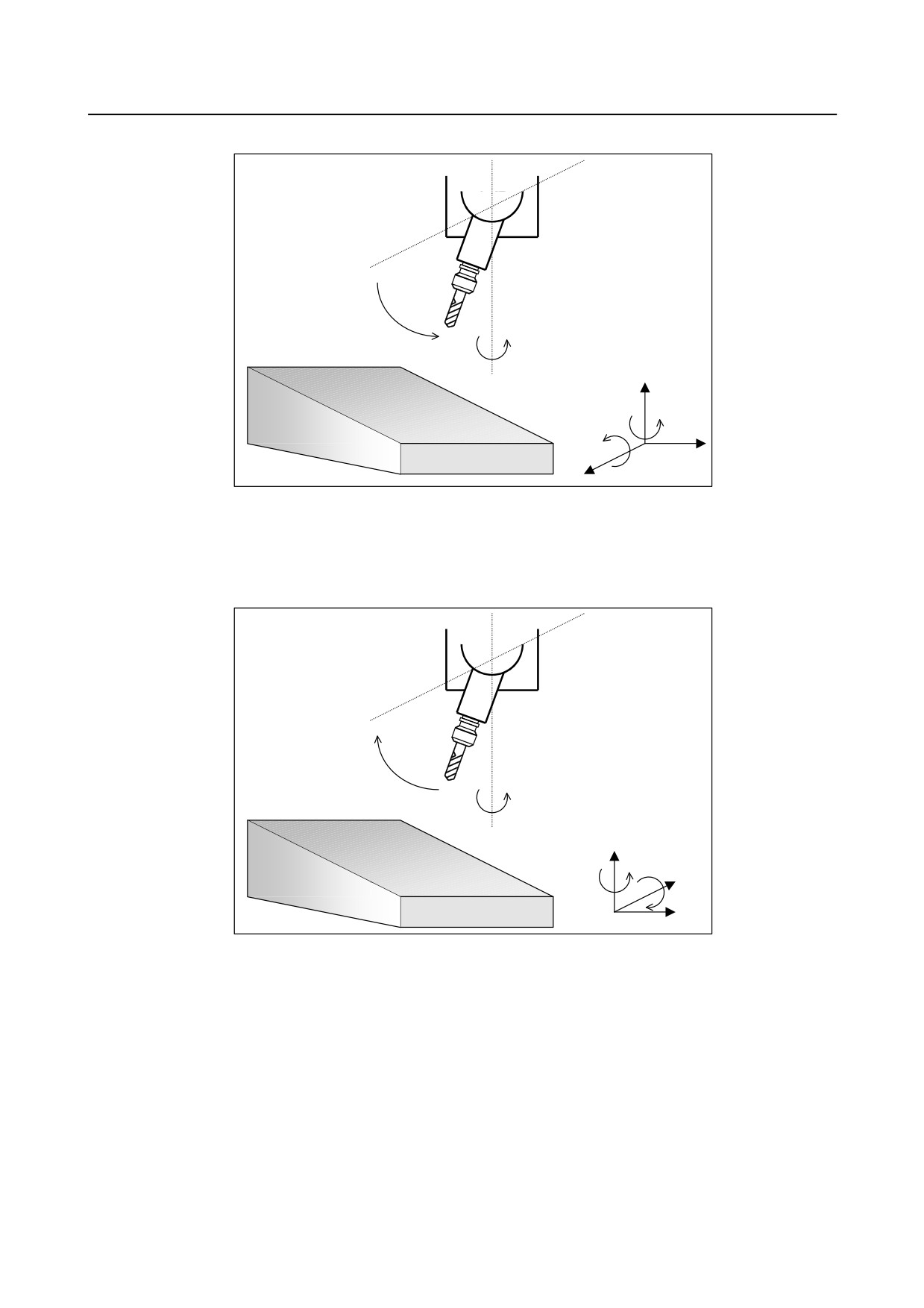
Let Vx, Vy, Vz, Lc, a, b, and c be as follows :
Vx,Vy,Vz: Tool compensation vectors along the X-axis, Y-axis, and Z-axis
Lc
:
Offset value
a,b,c
:
Absolute coordinates on the A-axis, B-axis and C-axis
Then, the tool compensation vector on each axis in each machine configuration is indicated below.
- 268 -
B-64484EN-2/02
PROGRAMMING
6.COMPENSATION FUNCTION
(1) A-axis and C-axis, with the tool axis on the Z-axis
A
C
Z
Workpiece
C
A
Y
X
Vx = Lc * sin(a) * sin(c)
Vy = -Lc * sin(a) * cos(c)
Vz = Lc * cos(a)
(2) B-axis and C-axis, with the tool axis on the Z-axis
B
C
Z
Workpiece
C
B
Y
X
Vx = Lc * sin(b) * cos(c)
Vy = Lc * sin(b) * sin(c)
Vz = Lc * cos(b)
- 269 -
6.COMPENSATION FUNCTION
PROGRAMMING
B-64484EN-2/02
(3) A-axis and B-axis, with the tool axis on the X-axis
A
B
Z
A
Workpiece
X
B
Y
Vx = Lc * cos(b)
Vy = Lc * sin(b) * sin(a)
Vz = -Lc * sin(b) * cos(a)
(4) A-axis and B-axis, with the tool axis on the Z-axis, and the B-axis used as the master
B
A
Z
B
X
Workpiece
Y
A
Vx = Lc * cos(a) * sin(b)
Vy = -Lc * sin(a)
Vz = Lc * cos(a) * cos(b)
- 270 -
B-64484EN-2/02
PROGRAMMING
6.COMPENSATION FUNCTION
(5) A-axis and B-axis, with the tool axis on the Z-axis, and the A-axis used as the master
A
B
Z
B Y
Workpiece
X
A
Vx = Lc * sin(b)
Vy = -Lc * sin(a) * cos(b)
Vz = Lc * cos(a) * cos(b)
-
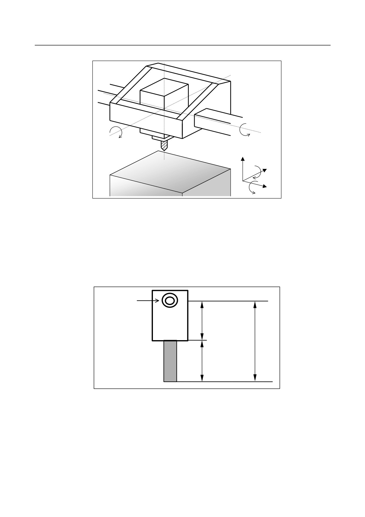
Tool holder offset
The machine-specific length from the rotation center of the tool rotation axes (A- and B-axes, A- and
C-axes, and B- and C-axes) to the tool mounting position is referred to as the tool holder offset. Unlike a
tool length offset value, a tool holder offset value is set in parameter No.19666. When tool axis direction
tool length compensation is applied, the sum of the tool holder offset and tool length offset is handled as a
tool length for compensation calculation.
Rotation center
Tool holder offset
Tool
length
Tool length offset
Fig. 6.15 (b)Tool Holder Offset
-
Parameter-based rotation angle specification
A tool compensation vector is found from the coordinates on the rotation axes for controlling the tool axis
direction. However, the configuration of some machines is such that the tool axis is inclined using a fixed
attachment. In such a case, the rotation angles of the rotation axes can be set using parameters.
Set bit 1 (RAP) of parameter No. 19650 to 1, and set the coordinates in parameter No. 19658.
- 271 -
6.COMPENSATION FUNCTION
PROGRAMMING
B-64484EN-2/02
-
Rotation axis origin compensation
This function compensates for a slight shift of the rotation axis origin caused, for example, by thermal
displacement. Specify a compensation value in parameter No. 19660.
When the tool axis is on the Z-axis, and the rotation axes are the B-axis and C-axis, a compensation
vector is calculated as follows :
Xp = Lc * sin(B-Bz) * cos(C-Cz)
Yp = Lc * sin(B-Bz) * sin(C-Cz)
Zp = Lc * cos(B-Bz)
Xp,Yp,Zp
: Compensation pulse on each axis after origin shift compensation
Lc
: Offset value
B,C
: Machine position on B-axis and C-axis
Bz,Cz
: Origin compensation value on B-axis and C-axis
-
Rotation axis offset
Set offsets relative to the rotation angles of the rotation axes in parameter No. 19659. The compensation
vector calculation formula is the same as that used for rotation axis origin compensation, except that Bp
and Cp are changed to rotation axis offsets.
When rotation axis origin compensation and rotation offsetting are set at the same time, both
compensations are performed.
When the tool axis is on the Z-axis, and the rotation axes are the B-axis and C-axis, compensation vector
calculation is performed as follows :
Xp = Lc * sin(B-(Bz+Bo)) * cos(C-(Cz+Co))
Yp = Lc * sin(B-(Bz+Bo)) * sin(C-(Cz+Co))
Zp = Lc * cos(B-(Bz+Bo))
Bz,Cz
: B-axis and C-axis origin compensation values
Bo,Co
: B-axis and C-axis rotation axis offset values
Limitation
- Automatic reference position return command (G28, G29, G30)
Never specify an automatic reference position return command (G28, G29, or G30) in tool axis direction
tool length compensation mode.
- Machine coordinate system positioning (G53)
Machine coordinate system positioning (G53) cannot be performed in tool length compensation mode in
tool axis direction.
6.15.1 Control Point Compensation of Tool Length Compensation
Along Tool Axis
Normally, the control point of tool length compensation along the tool axis is the point of intersection of
the centers of two rotation axes. The machine coordinates also indicate this control point.
This section explains the compensation performed when the centers of the two rotation axes do not
intersect and also explains how to place the control point at a convenient position on the machine.
Explanation
-
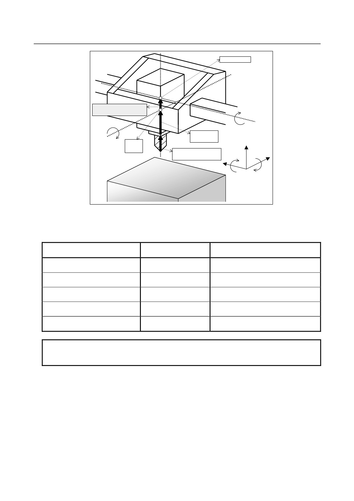
Compensation of the rotation centers of two rotation axes
Compensation when the rotation centers of two rotation axes do not match is performed.
The length from the tool mounting position to the first rotation axis center is set as the tool holder offset
value in parameter No. 19666.
The vector from the first rotation axis center to the second rotation axis center is set as the rotation center
compensation vector in parameter No. 19661. Since parameter No. 19661 is an axis type parameter, the
compensation amount for three axes (X, Y, and Z) can be set in this parameter.
- 272 -
B-64484EN-2/02
PROGRAMMING
6.COMPENSATION FUNCTION
B axis center
Rotation center
compensation vector
B
Tool holder
offset
A
A axis
Z
center
Tool length
B
X
compensation amount
Y
A
Workpiece
Fig. 6.15.1 (a) Compensation of Rotation Centers of Two Rotation Axes
According to the machine type, set the values listed in the Table 6.15 (a):
Table 6.15 (a) Setting the Tool Holder Offset and Rotation Center Compensation Vector
Tool holder offset
Rotation center compensation vector
Machine type
Parameter No. 19666
Parameter No. 19661
(1) A- and C-axes. Tool axis is Z-axis.
Length from tool mounting
Vector from A-axis center to C-axis center
position to A-axis center
(2) B- and C-axes. Tool axis is Z-axis.
Length from tool mounting
Vector from B-axis center to C-axis center
position to B-axis center
(3) A- and B-axes. Tool axis is X-axis.
Length from tool mounting
Vector from B-axis center to A-axis center
position to B-axis center
(4) A- and B-axes. Tool axis is Z-axis.
Length from tool mounting
Vector from A-axis center to B-axis center
B-axis is master.
position to A-axis center
(5) A- and B-axes. Tool axis is Z-axis.
Length from tool mounting
Vector from B-axis center to A-axis center
A-axis is master
position to B-axis center
NOTE
When using the spindle center compensation described blow, set the length from
the tool mounting position to the spindle center as the tool holder offset.
-
Spindle center compensation
Compensation of the spindle center is performed.
The amount of spindle center compensation is set in parameter No. 19662. Since parameter No. 19662 is
an axis type parameter, the compensation amount for three axes (X, Y, and Z) can be set in this
parameter.
- 273 -
6.COMPENSATION FUNCTION
PROGRAMMING
B-64484EN-2/02
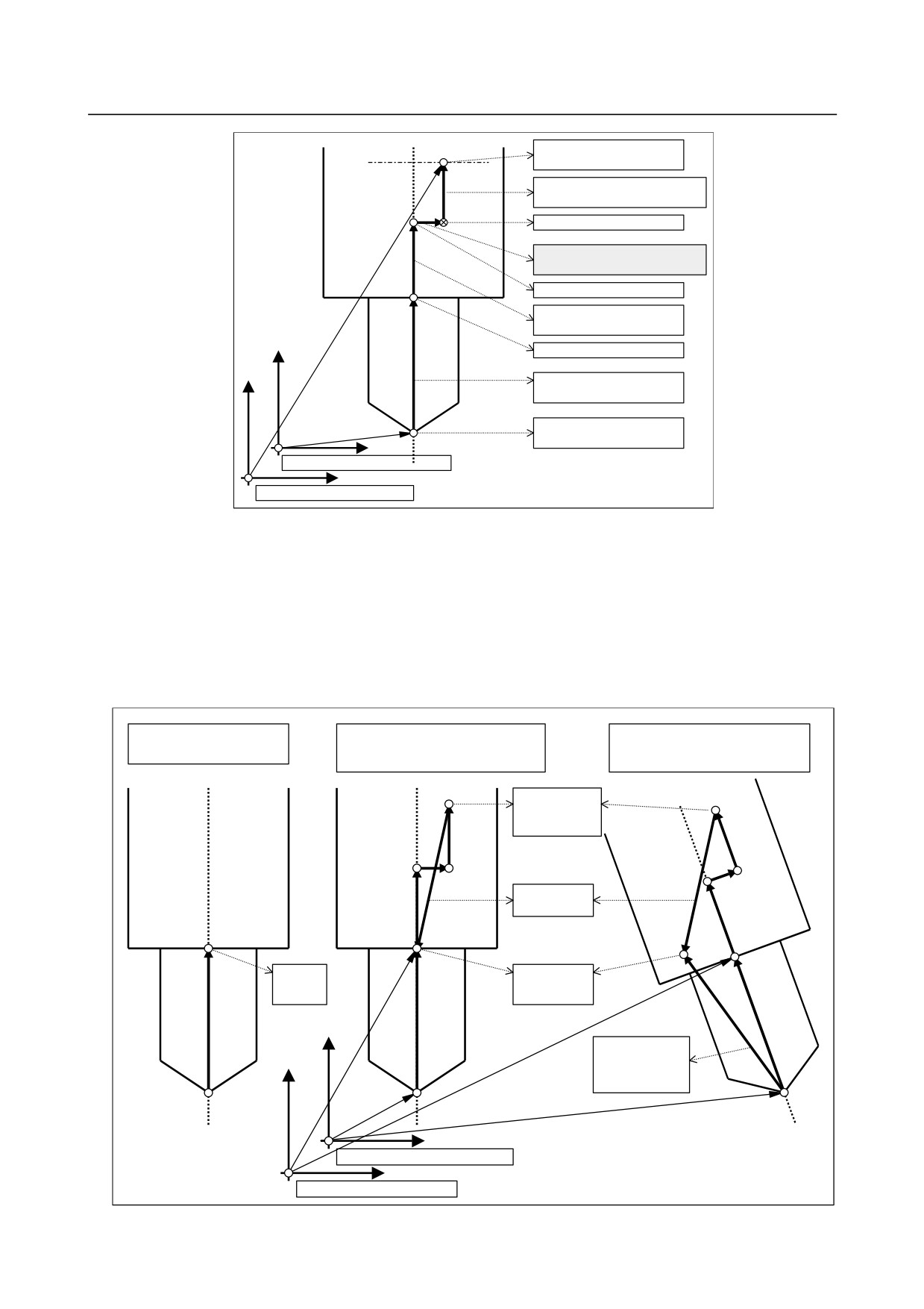
Second rotation axis
center (control point)
Rotation center compensation
vector parameter(No.19661)
First rotation axis center
Spindle center compensation
vector parameter(No.19662)
Spindle center
Tool holder offset
parameter(No.19666)
Tool mounting position
Tool length
compensation amount
Tool tip
(programmed point)
Workpiece coordinate origin
Machine coordinate origin
Fig. 6.15.1 (b) Spindle Center Compensation
-
Shifting the control point
Conventionally, the center of a rotation axis was used as the control point. The control point can now be
shifted as shown in the figure below.
Then, when the rotation axis is at the 0-degree position also in tool length compensation along the tool
axis
(G43.1), the control point can be set to the same position as that for ordinary tool length
compensation (G43).
The control point here is indicated with machine coordinates.
When linear interpolation is specified, for example, this control point moves linearly.
Ordinary tool length
Tool lenght compensation along
Tool length compensation along
compensation(G43)
tool axis (G43.1):
tool axis (G43.1) :
Whin tool is not tilted
When tool is tilted
Control
point before
shift
Shift
vector
Control
Control
point
point
Tool length
compensation
vector
Workpiece coordinate origin
Machine coordinate origin
Fig. 6.15.1 (c) Shift of the Control Point
- 274 -

B-64484EN-2/02
PROGRAMMING
6.COMPENSATION FUNCTION
The method of shifting the control point can be selected using the following parameters:
Table 6.15 (b) Methods of Shifting the Control Point
Bit 5 (SVC) of
Bit 4 (SPR) of
Shift of controlled point
parameter No. 19665
parameter No. 19665
0
-
Shift is not performed an not done conventionally.
The controlled point is shifted according to the result of the
following automatic calculation:
1
0
-(rotation center compensation vector (parameter No. 19661)
+ spindle center compensation vector (parameter No. 19662)
+ tool holder offset (parameter No. 19666))
The controlled point is shifted.
1
1
As the shift vector, the vector set in parameter No. 19667 is
used.
- Equation for each machine type
Vx, Vy, Vz
: Tool length compensation vector
A, B, C
: Absolute coordinates of A-, B-, and C-axes
To
: Tool offset value
Ho
: Tool holder offset value
Jx, Jy, Jz
: Rotation center compensation vector
Cx, Cy, Cz
: Spindle center compensation vector
Sx, Sy, Sz
: Shift vector
Suppose the above. Then, the tool length compensation vector for each axis is calculated depending on
the machine type, as follows:
(1) A-axis and C-axis. The tool axis is the Zaxis.
⎡Vx⎤
⎡cos
C
−sin
C
0⎤⎛⎡1
0
0
⎤⎡
Cx
⎤
⎡Jx⎤⎞
⎡Sx⎤
⎜
⎟
⎢
⎥
⎢
⎥
⎢
⎥⎢
⎥
⎢
⎥
⎢
⎥
Vy
=
sin
C
cos
C
0
⎜
0
cos
A
−sin
A
Cy
+
Jy
⎟
+
Sy
⎢
⎥
⎢
⎥
⎢
⎥⎢
⎥
⎢
⎥
⎢
⎥
⎜
⎟
⎢Vz⎥
⎢
0
0
1⎥
⎢0
sin
A
cos
A
⎥⎢To +
Ho
+Cz⎥
⎢Jz⎥
⎢Sz⎥
⎣
⎦
⎣
⎦⎝⎣
⎦⎣
⎦
⎣
⎦⎠
⎣
⎦
(2) B-axis and C-axis. The tool axis is the Z-axis.
⎡Vx⎤
⎡cos
C
−sin
C
0⎤⎛⎡
cos
B
0
sin
B⎤⎡
Cx
⎤
⎡Jx⎤⎞
⎡Sx⎤
⎜
⎟
⎢
⎥
⎢
⎥
⎢
⎥⎢
⎥
⎢
⎥
⎢
⎥
Vy
=
sin
C
cos
C
0
⎜
0
1
0
Cy
+
Jy
⎟
+
Sy
⎢
⎥
⎢
⎥
⎢
⎥⎢
⎥
⎢
⎥
⎢
⎥
⎜
⎟
⎢Vz⎥
⎢
0
0
1⎥
⎢−sin
B
0
cos
B⎥⎢To+
Ho
+Cz⎥
⎢Jz⎥
⎢Sz⎥
⎣
⎦
⎣
⎦⎝⎣
⎦⎣
⎦
⎣
⎦⎠
⎣
⎦
(3) A-axis and B-axis. The tool axis is the X-axis.
⎡Vx⎤
⎡1
0
0
⎤⎛⎡
cos
B
0
sin
B⎤⎡To+
Ho
+Cx⎤
⎡Jx⎤⎞
⎡Sx⎤
⎜
⎟
⎢
⎥
⎢
⎥
⎢
⎥⎢
⎥
⎢
⎥
⎢
⎥
Vy
=
0
cos
A
−sin
A
⎜
0
1
0
Cy
+
Jy
⎟
+
Sy
⎢
⎥
⎢
⎥
⎢
⎥⎢
⎥
⎢
⎥
⎢
⎥
⎜
⎟
⎢Vz⎥
⎢0
sin
A
cos
A
⎥
⎢−sin
B
0
cos
B⎥⎢
Cz
⎥
⎢Jz⎥
⎢Sz⎥
⎣
⎦
⎣
⎦⎝⎣
⎦⎣
⎦
⎣
⎦⎠
⎣
⎦
(4) A-axis and B-axis. The tool axis is the Z-axis, and the B-axis is the master.
⎡Vx⎤
⎡
cos
B
0
sin
B⎤⎛⎡1
0
0
⎤⎡
Cx
⎤
⎡Jx⎤⎞
⎡Sx⎤
⎜
⎟
⎢
⎥
⎢
⎥
⎢
⎥⎢
⎥
⎢
⎥
⎢
⎥
Vy
=
0
1
0
⎜
0
cosA
−sin
A
Cy
+
Jy
⎟
+
Sy
⎢
⎥
⎢
⎥
⎢
⎥⎢
⎥
⎢
⎥
⎢
⎥
⎜
⎟
⎢Vz⎥
⎢−sin
B
0
cos
B⎥
⎢0
sin
A
cos
A
⎥⎢To +
Ho
+Cz⎥
⎢Jz⎥
⎢Sz⎥
⎣
⎦
⎣
⎦⎝⎣
⎦⎣
⎦
⎣
⎦⎠
⎣
⎦
(5) A-axis and B-axis. The tool axis is the Z-axis and the A-axis is the master.
⎡Vx⎤
⎡1
0
0
⎤⎛⎡
cos
B
0
sin
B⎤⎡
Cx
⎤
⎡Jx⎤⎞
⎡Sx⎤
⎜
⎟
⎢
⎥
⎢
⎥
⎢
⎥⎢
⎥
⎢
⎥
⎢
⎥
Vy
=
0
cos
A
−sin
A
⎜
0
1
0
Cy
+
Jy
⎟
+
Sy
⎢
⎥
⎢
⎥
⎢
⎥⎢
⎥
⎢
⎥
⎢
⎥
⎜
⎟
⎢Vz⎥
⎢0
sin
A
cos
A
⎥
⎢−sin
B
0
cos
B⎥⎢To+
Ho
+Cz⎥
⎢Jz⎥
⎢Sz⎥
⎣
⎦
⎣
⎦⎝⎣
⎦⎣
⎦
⎣
⎦⎠
⎣
⎦
The shift vector (Sx, Sy, Sz) is calculated as follows:
(A) When bit 5 (SVC) of parameter No. 19665 = 0, the vector is set to 0.
(B) When bit 5 (SVC) of parameter No. 19665 = 1, and bit 4 (SBP) of parameter No. 19665 = 0:
When the machine type is other than (3)
- 275 -
6.COMPENSATION FUNCTION
PROGRAMMING
B-64484EN-2/02
⎡
Sx⎤
⎡
Cx
+
Jx
⎤
⎢
⎥
⎢
⎥
Sy
=
−
Cy
+
Jy
⎢
⎥
⎢
⎥
⎢Sz⎥
⎢Cz
+
Jz
+
Ho⎥
⎣
⎦
⎣
⎦
When the machine type is (3)
⎡
Sx⎤
⎡Cx
+
Jx
+
Ho⎤
⎢
⎥
⎢
⎥
Sy
=
−
Cy
+
Jy
⎢
⎥
⎢
⎥
⎢Sz⎥
⎢
Cz
+
Jz
⎥
⎣
⎦
⎣
⎦
(C) When bit 5 (SVC) of parameter No. 19665 = 1, and bit 4 (SBP) of parameter No. 19665 = 1, the
vector specified in parameter No. 19667 is set.
6.16 SPINDLE UNIT COMPENSATION, NUTATING ROTARY
HEAD TOOL LENGTH COMPENSATION
Overview
For a machine with multiple spindle units, characteristic parameters, compensation amounts, tool axis
directions, etc. can be set for each unit. By compensating a selected unit during machining, it is possible
to create programs not influenced by spindle unit compensation amounts/tool length compensation
amounts.
If a spindle unit is controlled with a rotation axis, the compensation amount is automatically calculated
from the rotation angle of the rotation axis to perform compensation.
Application example
As shown in Fig. 6.16 (a), let us consider a spindle unit controlled with the C-axis. When the rotation axis
(C-axis) is rotated, the spindle unit compensation vector/nutating rotary head tool length compensation
vector are calculated from that angle to perform compensation.
When C axis is at standard position
When C axis has rotated 180° from standard position
C
C
VS0
VS0
S
S
VS1
VS1
Z
Y
VN
VN
P
P
X
S
:
Reference point
P
:
Specified point
:
Standard tool
VS0 , VS1
:
Vector of spindle unit compensation
VN
:
Vector of nutating rotary head tool length compensation
If a standard tool is not used, VN is the vector from the tool center point to the specified point.
Fig. 6.16 (a) Example of vector of spindle unit compensation and nutating rotary head tool length
compensation
- 276 -

B-64484EN-2/02
PROGRAMMING
6.COMPENSATION FUNCTION
Format
-
Spindle unit compensation
G44.9 ; Enables spindle unit compensation
G49.9 ; Disables spindle unit compensation
The G44.9 command calculates the spindle unit compensation amount from the preset data and the angle
of the rotation axis, and enables compensation.
The G49.9 command cancels spindle unit compensation.
If, in G44.9 mode, the rotation axis related to spindle unit compensation is rotated, the vector is
recalculated by using the end point value of that rotation axis.
-
Nutating rotary head tool length compensation
G43.3 Hn ; Enables nutating rotary head tool length compensation
G49
; Disables nutating rotary head tool length compensation
n : Tool compensation amount number
The G43.3 command calculates the tool length compensation amount from the tool compensation amount
data specified for n and the angle of the rotation axis, and enables compensation.
The G49 command cancels tool length compensation.
If, in G43.3 mode, the rotation axis related to tool length compensation is rotated, the tool length
compensation vector is recalculated by using the end point value of that rotation axis.
-
Mode retention function
When the power is turned on or the system is reset in spindle unit compensation (G44.9) and nutating
rotary head tool length compensation (G43.3), G44.9 and G43.3 modes, as well as the tool compensation
amount and the vector, are retained.
(1) Retention of G44.9 and G43.3 modes when the power is turned on or the system is reset
By making either of the following parameter settings, G44.9 mode is retained when the power is
turned on or the system is reset.
•
Bit 6 (CLR) of parameter No. 3402 is set to 0.
•
Bit 6 (CLR) of parameter No. 3402 is set to 1 and bit 3 (C27) of parameter No. 3409 is set to 1.
By making either of the following parameter settings, G43.3 mode and H code are retained when the
power is turned on or the system is reset.
•
Bit 6 (CLR) of parameter No. 3402 is set to 0.
•
Bit 6 (CLR) of parameter No. 3402 is set to 1, bit 0 (C08) of parameter No. 3407 is set to 1, and
bit 7 (CFH) of parameter No. 3409 is set to 1.
(2) Calculation of G44.9 and G43.3 vectors when the power is turned on
By setting bit 2 (SCV) of parameter No. 25860 to 1, the spindle unit compensation vector is
calculated when the power is turned on.
By setting bit
3 (NCV) of parameter No. 25860 to 1, the nutating rotary head tool length
compensation vector is calculated when the power is turned on.
Parameter
#7
#6
#5
#4
#3
#2
#1
#0
3402
CLR
[Input type] Parameter input
[Data type] Bit path
#6 CLR Reset button on the MDI panel, external reset signal, reset and rewind signal, and
emergency stop signal
0: Cause reset state.
1: Cause clear state.
- 277 -
6.COMPENSATION FUNCTION
PROGRAMMING
B-64484EN-2/02
For the reset and clear states, refer to Appendix in the OPERATOR’S MANUAL.
#7
#6
#5
#4
#3
#2
#1
#0
3406
C07
C06
C05
C04
C03
C02
C01
#7
#6
#5
#4
#3
#2
#1
#0
3407
C15
C14
C13
C12
C11
C10
C09
C08
#7
#6
#5
#4
#3
#2
#1
#0
3408
C23
C22
C21
C20
C19
C18
C17
C16
#7
#6
#5
#4
#3
#2
#1
#0
3409
CFH
C30
C29
C28
C27
C26
C25
C24
[Input type] Parameter input
[Data type] Bit
C01 to C30 If bit 6 (CLR) of parameter No.3402 is set to 1, set a group of G codes to be placed in the
cleared state when the CNC is reset by the
key of the MDI panel, the external reset
signal, the reset & rewind signal, or the emergency stop signal.
The Table 6.16 (a) indicates the correspondence between bits and G code groups
The setting of a bit has the following meaning:
0: Places the G code group in the cleared state.
1: Does not place G code group in the cleared state.
Table 6.16 (a)
Parameter
G code group
C01
01
C02
02
C03
03
:
:
C30
30
#7 CFH When bit 6 (CLR) of parameter No.3402 is 1, the
key on the MDI panel, the
external reset signal, the reset and rewind signal, or emergency stop will,
0: Clear F codes, H codes (for the M series), D codes (for the M series), and T codes
(for the T series).
1: Not clear F codes, H codes (for the M series), D codes (for the M series), and T
codes (for the T series).
#7
#6
#5
#4
#3
#2
#1
#0
25860
NCV
SCV
[Input type] Parameter input
[Data type] Bit path
#2 SCV At power-on, a spindle unit compensation vector is:
0: Not calculated.
1: Calculated.
NOTE
This parameter is effective in the case of either of the following
settings:
• Bit 6 (CLR) of parameter No. 3402 = 0
• Bit 6 (CLR) of parameter No. 3402 = 1 and bit 3 (C27) of
parameter No. 3409 = 1
- 278 -
B-64484EN-2/02
PROGRAMMING
6.COMPENSATION FUNCTION
#3 NCV At power-on, an nutating rotary head tool length compensation vector is:
0: Not calculated.
1: Calculated.
NOTE
This parameter is effective in the case of either of the following
settings:
• Bit 6 (CLR) of parameter No. 3402 = 0
• Bit 6 (CLR) of parameter No. 3402 = 1, bit 0 (C08) of parameter
No. 3407 = 1, and bit 7 (CFH) of parameter No. 3409 = 1
- 279 -
7. MEMORY OPERATION
USING Series 15 FORMAT
PROGRAMMING
B-64484EN-2/02
7 MEMORY OPERATION USING Series 15
PROGRAM FORMAT
Overview
Memory operation of the program registered in Series 15 program format is possible by setting the setting
bit 1 (FCV) of parameter No. 0001 to 1.
Explanation
Data formats for tool radius compensation, subprogram call, and canned cycles are different between the
Series 30i and Series 15. The Series 15 program formats can be processed for memory operation.
Other data formats must comply with the Series 30i. When a value out of the specified range for the
Series 30i is registered, an alarm occurs. Functions not available in the Series 30i cannot be registered or
used for memory operation.
-
Address for the tool radius compensation offset number
Offset numbers are specified by address D in the Series 15.
When an offset number is specified by address D, the modal value specified by address H is replaced with
the offset number specified by address D.
-
Subprogram call
If a subprogram number of more than four digits is specified, the four low-order digits are regarded as the
subprogram number.
If no repeat count is specified, 1 is assumed.
Table 7 (a) Subprogram call program format
CNC
Program format
M98 P{{{{ L{{{{ ;
Series 15
P : Subprogram number
L : Repetition count (1 to 9999)
M98 P{{{
;
Series 30
Repetition count
Subprogram number (1 to 9999)
If, however, the custom macro option is enabled, both formats can be used.
-
Address for the canned cycle repetition count for drilling
The Series 15 and this CNC use different addresses for the canned cycle repetition count for drilling as
listed in Table 7 (b).
Table 7 (b) Address for the canned cycle repetition count for drilling
CNC
Address
Series 15
L
Series 30
K
- 280 -

7.MEMORY OPERATION
B-64484EN-2/02
PROGRAMMING
USING Series 15 FORMAT
7.1
MULTIPLE REPETITIVE CYCLE
The multiple repetitive cycle is canned cycles to make CNC programming easy. For instance, the data of
the finish work shape describes the tool path for rough machining. And also, a canned cycles for the
threading is available.
NOTE
1 Explanatory figures in this section use the ZX plane as the selected plane,
diameter programming for the X-axis, and radius programming for the Z-axis.
When radius programming is used for the X-axis, change U/2 to U and X/2 to X.
2 A multiple repetitive cycle can be performed on any plane (including parallel
axes for plane definition).
- 281 -
7. MEMORY OPERATION
USING Series 15 FORMAT
PROGRAMMING
B-64484EN-2/02
7.1.1
Stock Removal in Turning (G71.7)
There are two types of stock removal in turning : Type I and II.
To use type II, the "multiple repetitive canned cycle 2" option function is required.
Format
ZpXp plane
G71.7 P(ns) Q(nf) U(Δu) W(Δw) I(Δi) K(Δk) D(Δd) F(f ) S(s ) T(t );
N (ns) ;
The move commands for the target figure from A to A’ to B are specified in
- - -
the blocks with sequence numbers ns to nf.
N (nf) ;
YpZp plane
G71.7 P(ns) Q(nf) V(Δw) W(Δu) J(Δk) K(Δi) D(Δd) F(f ) S(s ) T(t );
N (ns) ;
- - -
N (nf) ;
XpYp plane
G71.7 P(ns) Q(nf) U(Δw) V(Δu) I(Δk) J(Δi) D(Δd) F(f ) S(s ) T(t );
N (ns) ;
- - -
N (nf) ;
Δd
: Depth of cut
The cutting direction depends on the direction AA’.
ns
: Sequence number of the first block for the program of finishing shape.
nf
: Sequence number of the last block for the program of finishing shape.
Δu
: Distance of the finishing allowance in the direction of the second axis on the plane
(X-axis for the ZX plane)
Δw : Distance of the finishing allowance in the direction of the first axis on the plane (Z-axis
for the ZX plane)
Δi
: Distance of the finishing allowance for rough cutting in the direction of the second axis
on the plane (X-axis for the ZX plane)
Δk
: Distance of the finishing allowance for rough cutting in the direction of the first axis on
the plane (Z-axis for the ZX plane)
f,s,t : Any F , S, or T function contained in blocks ns to nf in the cycle is ignored, and the F,
S, or T function in this G71.7 block is effective.
Decimal
Unit
Diameter/radius programming
Sign
point input
Depends on the increment
Not
Δd
Radius programming
Not allowed
system for the reference axis.
required
Depends on the increment
Depends on diameter/radius programming
Δu
Required
Allowed
system for the reference axis.
for the second axis on the plane.
Depends on the increment
Depends on diameter/radius programming
Δw
Required
Allowed
system for the reference axis.
for the first axis on the plane.
Depends on the increment
Not
Δi
Radius programming
Allowed
system for the reference axis.
required
- 282 -
7.MEMORY OPERATION
B-64484EN-2/02
PROGRAMMING
USING Series 15 FORMAT
Decimal
Unit
Diameter/radius programming
Sign
point input
Depends on the increment
Not
Δk
Radius programming
Allowed
system for the reference axis.
required
(R)
C
B
A
(R)
Δd
(F)
45°
e
(F)
Target figure
Δu/2
+X
A’
(F): Cutting feed
ΔW
+Z
(R): Rapid traverse
e: Escaping amount(parameter No.5133)
Fig. 7.1.1 (a) Cutting path (type I) of the stock removal in turning without the finishing allowance for rough
cutting
C
B
(R)
A
(R)
Δd
(R)
(F)
45°
e
(F)
Target figure
Δi
Δu/2
+X
A’
(F): Cutting feed
ΔK
(R): Rapid traverse
+Z
ΔW
e: Escaping amount(parameter No.5133)
Fig. 7.1.1 (b) Cutting path (type I) of the stock removal in turning with the finishing allowance for rough
cutting
Explanation
-
Operations
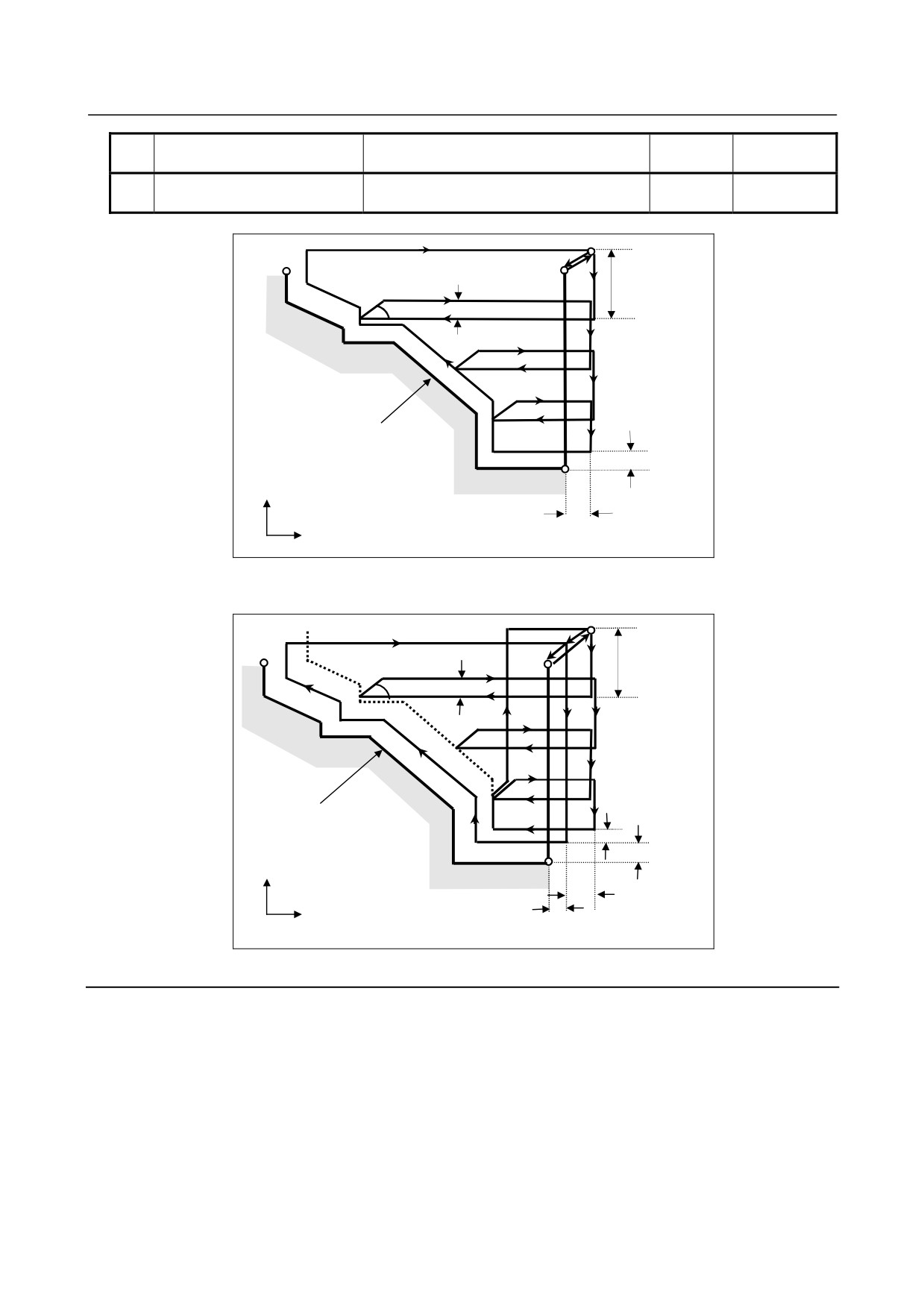
If the target figure from A to A' to B is provided by a program, the tool grinds by the depth of cut Δd. The
path differs as described below, depending on whether the finishing allowance for rough cutting is
specified or not.
(1) If the finishing allowance for rough cutting is not specified
The tool grinds by the depth of cut Δd, leaving the finishing allowances of Δu/2 and Δw, and after
the last cut, performs rough cutting as finishing in accordance with the target figure program.
- 283 -
7. MEMORY OPERATION
USING Series 15 FORMAT
PROGRAMMING
B-64484EN-2/02
(2) If the finishing allowance for rough cutting is specified
The tool grinds by the depth of cut Δd, leaving the finishing allowances of Δu/2+Δi and Δw+Δk, and
after the last cut, returns to the start point (A) and then performs rough cutting as finishing along the
target figure, to remove the allowances of Δi and Δk.
After rough cutting as finishing, the block next to the sequence block specified at Q is executed.
NOTE
1 F, S, and T functions which are specified in the move command between points
A and B are ineffective and those specified in G71.7 block or the previous block
are effective. M and second auxiliary functions are treated in the same way as F,
S, and T functions.
2 When an option of constant surface speed control is selected, G96 or G97
command specified in the move command between points A and B are
ineffective, and that specified in G71.7 block or the previous block is effective.
-
Escaping amount (e)
Set an escaping amount (e) in parameter No. 5133.
No.
Unit
Diameter/radius programming
Sign
Depends on the increment system for the
5133
Radius programming
Not required
reference axis.
-
Target figure
Patterns
The following four cutting patterns are considered. All of these cutting cycles cut the workpiece with
moving the tool in parallel to the first axis on the plane (Z-axis for the ZX plane). At this time, the signs
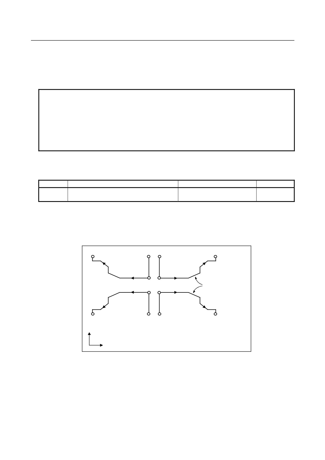
of the finishing allowances of Δu and Δw are as follows:
B
A
A
B
U(+)…W(+)
U(+)…W(-)
A'
A'
Both linear and
A'
A'
circular interpolation
are possible
U(-)…W(+)
U(-)…W(-)
B
A
A
B
+X
+Z
Fig. 7.1.1 (c) Four target figure patterns
Limitation
(1) For U(+), a figure for which a position higher than the cycle start point is specified cannot be
machined.
For U(-), a figure for which a position lower than the cycle start point is specified cannot be
machined.
(2) For type I, the figure must show monotone increase or decrease along the first and second axes on
the plane.
(3) For type II, the figure must show monotone increase or decrease along the first axis on the plane.
- 284 -
7.MEMORY OPERATION
B-64484EN-2/02
PROGRAMMING
USING Series 15 FORMAT
-
Start block
In the start block in the program for a target figure (block with sequence number ns in which the path
between A and A’ is specified), G00 or G01 must be specified. If it is not specified, alarm PS0065,
“G00/G01 IS NOT IN THE FIRST BLOCK OF SHAPE PROGRAM” is issued.
When G00 is specified, positioning is performed along A-A’. When G01 is specified, linear interpolation
is performed with cutting feed along A-A’. In this start block, also select type I or II.
-
Check functions
During cycle operation, whether the target figure shows monotone increase or decrease is always
checked.
NOTE
When tool nose radius compensation is applied, the target figure to which
compensation is applied is checked.
The following checks can also be made.
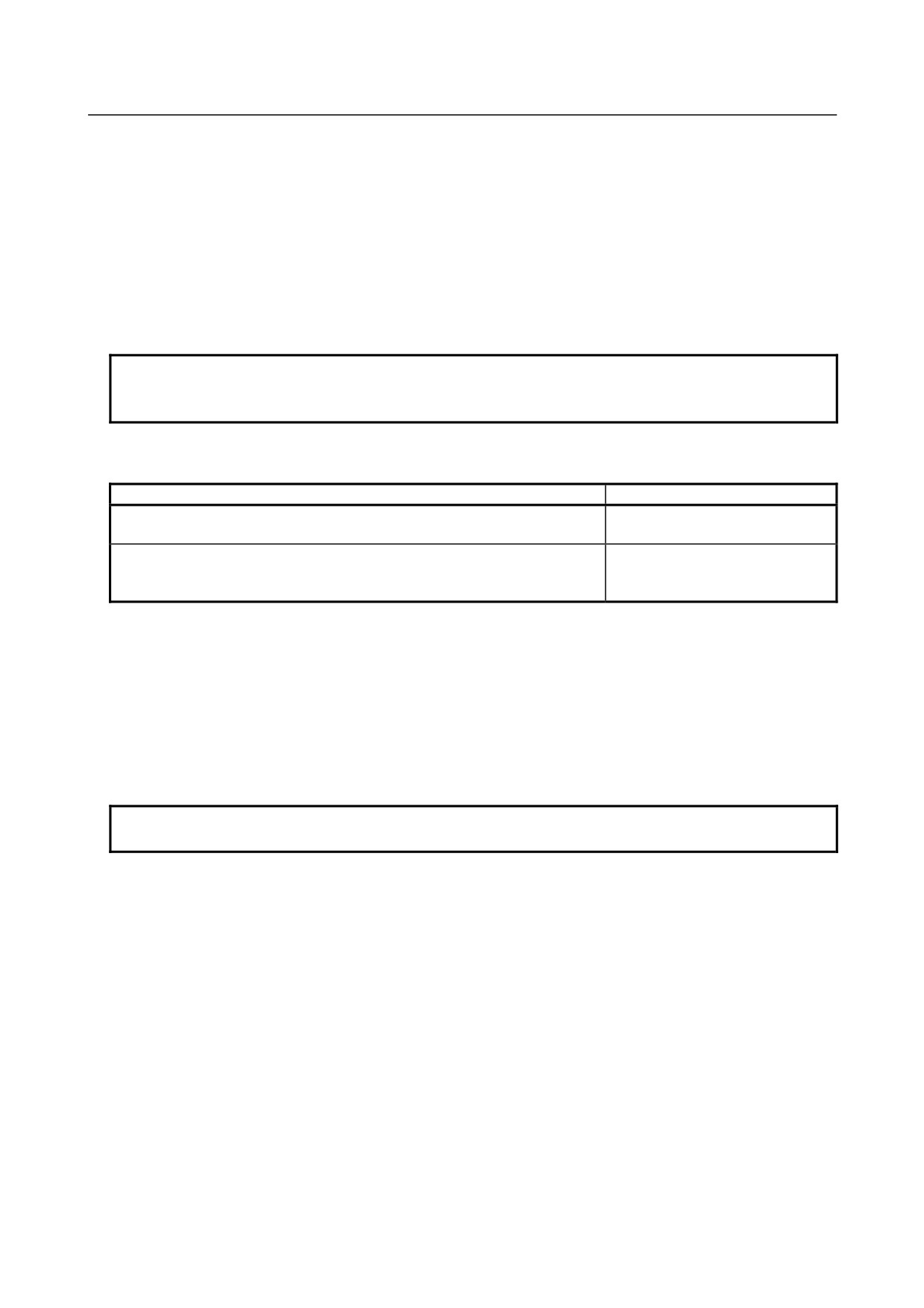
Check
Related parameter
Checks that a block with the sequence number specified at address Q is
Enabled when bit 2 (QSR) of
contained in the program before cycle operation.
parameter No. 5102 is set to 1.
Checks the target figure before cycle operation.
Enabled when bit 2 (FCK) of
(Also checks that a block with the sequence number specified at address Q is
parameter No. 5104 is set to 1.
contained.)
-
Types I and II
Selection of type I or II
For G71.7, there are types I and II.
When the target figure has pockets, be sure to use type II.
Escaping operation after rough cutting in the direction of the first axis on the plane (Z-axis for the ZX
plane) differs between types I and II. With type I, the tool escapes to the direction of 45 degrees. With
type II, the tool cuts the workpiece along the target figure. When the target figure has no pockets,
determine the desired escaping operation and select type I or II.
NOTE
To use type II, the multiple repetitive canned cycle II option is required.
Selecting type I or II
In the start block for the target figure (sequence number ns), select type I or II.
(1) When type I is selected
Specify the second axis on the plane (X-axis for the ZX plane). Do not specify the first axis on the
plane (Z-axis for the ZX plane).
(2) When type II is selected
Specify the second axis on the plane (X-axis for the ZX plane) and first axis on the plane (Z-axis for
the ZX plane).
To use type II without movement along the first axis on the plane (Z-axis for the ZX plane) in the
first block, specify the first axis with a travel distance of 0.
-
Type I
(1) In the block with sequence number ns, only the second axis on the plane (X-axis for the ZX plane)
must be specified.
- 285 -
7. MEMORY OPERATION
USING Series 15 FORMAT
PROGRAMMING
B-64484EN-2/02
Example
ZX plane
G71.7 P100 Q200
;
N100 X_ ;(Specifies only the second axis on the plane.)
: ;
: ;
N200
;
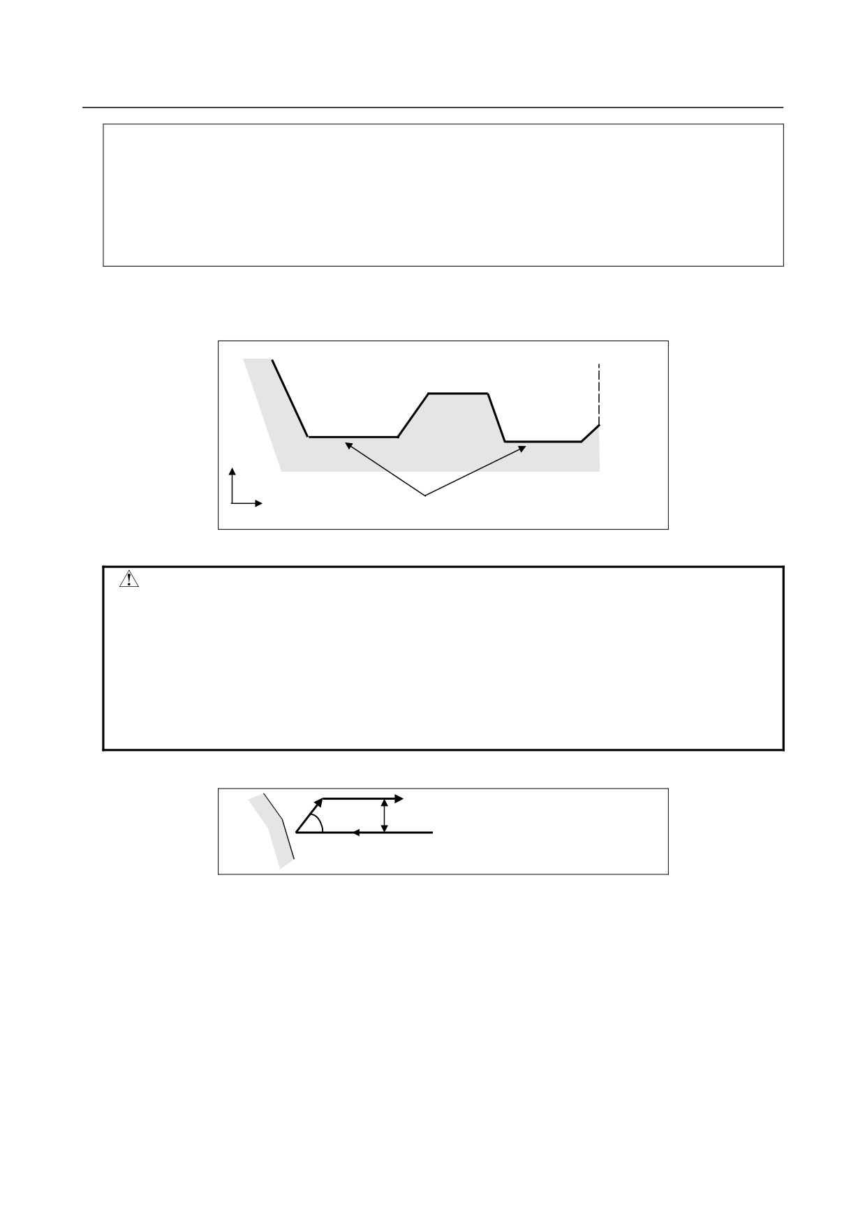
(2) The figure along path A'-B must show monotone increase or decrease in the directions of both axes
forming the plane (Z- and X-axes for the ZX plane). It must not have any pocket as shown in the Fig.
7.1.1 (d).
B
A
A’
X
Z
No pockets are allowed.
Fig. 7.1.1 (d) Figure which does not show monotone increase or decrease (type I)
CAUTION
If a figure does not show monotone change along the first or second axis on the
plane, alarm PS0064, “THE FINISHING SHAPE IS NOT A MONOTONOUS
CHANGE(FIRST AXES)” or PS0329, “THE FINISHING SHAPE IS NOT A
MONOTONOUS CHANGE(SECOND AXES)” is issued. If the movement does
not show monotone change, but is very small, and it can be determined that the
movement is not dangerous, however, the permissible amount can be specified
in parameters Nos. 5145 and 5146 to specify that the alarm is not issued in this
case.
(3) The tool escapes to the direction of 45 degrees in cutting feed after rough cutting.
Escaping amount e (specified in the
45°
parameter No. 5133)
Fig. 7.1.1 (e) Cutting in the direction of 45 degrees (type I)
(4) Immediately after the last cutting, rough cutting is performed as finishing along the target figure. Bit
1 (RF1) of parameter No. 5105 can be set to 1 so that rough cutting as finishing is not performed. If,
however, the finishing allowance for rough cutting is specified, rough cutting as finishing is always
performed.
- 286 -
7.MEMORY OPERATION
B-64484EN-2/02
PROGRAMMING
USING Series 15 FORMAT
-
Type II
(R)
(F)
C
(R)
B
A
Δd
(R)
(F)
Δd
(F)
Target figure
Δu/2
A’
+X
(F): Cutting feed
ΔW
+Z
(R): Rapid traverse
Fig. 7.1.1 (f) Cutting path in stock removal in turning (type II)
When the target figure program from A to A’ to B is specified, the tool grinds by the depth of cut Δd. The
difference from type I is that the tool cuts up along the figure after rough cutting in the first axis on the
plane (Z-axis for the ZX plane).
The path differs as described below, depending on whether the finishing allowance for rough cutting is
specified or not.
(1) If the finishing allowance for rough cutting is not specified
The tool grinds by the depth of cut Δd, leaving the finishing allowances of Δu/2 and Δw, and after
grinding with the last cut (and after grinding the area of Pn to Pm in the Fig. 7.1.1 (f) because the
area is parallel to the Z-axis and is, therefore, regarded as a single pocket), returns to the start point
(A) and performs rough cutting as finishing in accordance with the target figure program, leaving the
allowances of Δu/2 and Δw.
(2) If the finishing allowance for rough cutting is specified
The tool grinds by the depth of cut Δd, leaving the finishing allowances of Δu/2+Δi and Δw+Δk, and
after the last cut, returns to the start point (A) and then performs rough cutting as finishing in
accordance with the target figure program, to remove the allowances of Δi and Δk.
After rough cutting as finishing, the block next to the sequence block specified at Q is executed.
Type II differs from type I in the following points:
(1) In the block with sequence number ns, the two axes forming the plane (X-axis and Z-axis for the ZX
plane) must be specified. To use type II without movement along the Z-axis on the ZX plane in the
first block, specify the Z axis with a travel distance of 0.
Example
ZX plane
G71.7 P100 Q200
;
N100 X_ Z_ ; (Specifies the two axes forming the plane.)
:;
:;
N200
;
(2) The figure need not show monotone increase or decrease in the direction of the second axis on the
plane (X-axis for the ZX plane) and it may have concaves (pockets).
- 287 -
7. MEMORY OPERATION
USING Series 15 FORMAT
PROGRAMMING
B-64484EN-2/02
+X
10
3
2
1
・・・
+Z
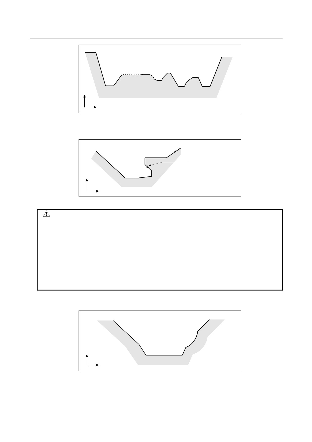
Fig. 7.1.1 (g) Figure having pockets (type II)
The figure must show monotone change in the direction of the first axis on the plane (Z-axis for the
ZX plane), however. The following figure cannot be machined.
Monotone change is not
observed along the Z-
axis.
+X
+Z
Fig. 7.1.1 (h) Figure which cannot be machined (type II)
CAUTION
For a figure along which the tool moves backward along the first axis on the
plane during cutting operation (including a vertex in an arc command), the
cutting tool may contact the workpiece. For this reason, for a figure which does
not show monotone change, alarm PS0064, "THE FINISHING SHAPE IS NOT A
MONOTONOUS CHANGE(FIRST AXES)" or PS0329, "THE FINISHING SHAPE
IS NOT A MONOTONOUS CHANGE(SECOND AXES)" is issued. If the
movement does not show monotone change, but is very small, and it can be
determined that the movement is not dangerous, however, the permissible
amount can be specified in parameter No. 5145 to specify that the alarm is not
issued in this case.
The first cut portion need not be vertical. Any figure is permitted if monotone change is shown in
the direction of the first axis on the plane (Z-axis for the ZX plane).
+X
+Z
Fig. 7.1.1 (i) Figure which can be machined (type II)
- 288 -
7.MEMORY OPERATION
B-64484EN-2/02
PROGRAMMING
USING Series 15 FORMAT
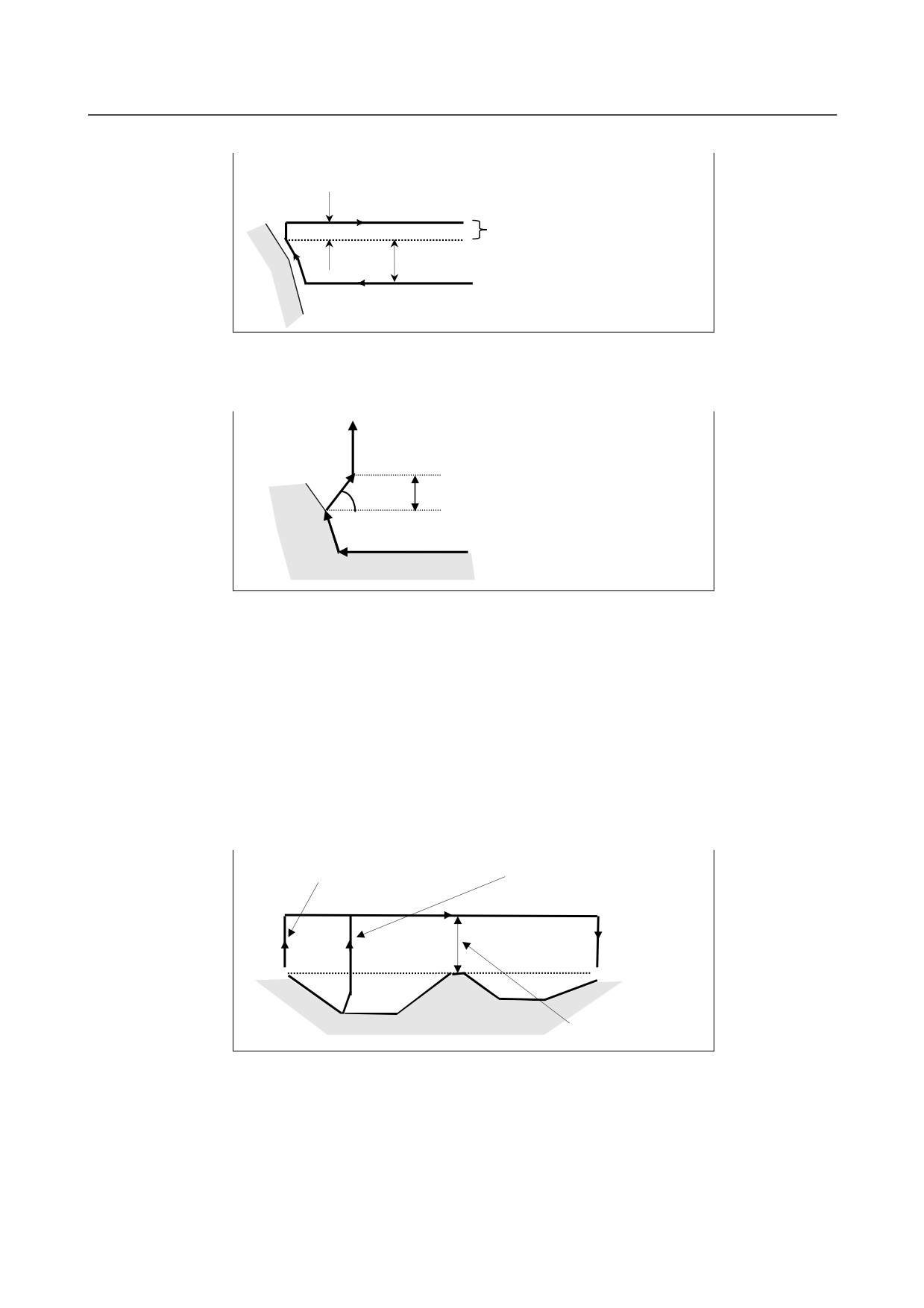
(3) After turning, the tool cuts the workpiece along its figure and escapes in cutting feed.
Escaping amount e (specified in the parameter No. 5133)
Escaping after cutting
Depth of cut Δd (specified in the command or
parameter No. 5132)
Fig. 7.1.1 (j) Cutting along the workpiece figure (type II)
The escaping amount after cutting (e) can be specified at parameter No. 5133.
When moving from the bottom, however, the tool escapes to the direction of 45 degrees.
e (specified in the parameter No. 5133)
45°
Bottom
Fig. 7.1.1 (k) Escaping from the bottom to the direction of 45 degrees
(4) When a position parallel to the first axis on the plane (Z-axis for the ZX plane) is specified in a
block in the program for the target figure, it is assumed to be at the bottom of a pocket.
(5) After all rough cutting terminates along the first axis on the plane (Z-axis for the ZX plane), the tool
temporarily returns to the cycle start point. At this time, when there is a position whose height equals
to that at the start point, the tool passes through the point in the position obtained by adding depth of
cut Δd to the position of the figure and returns to the start point.
Then, rough cutting is performed as finishing along the target figure. At this time, the tool passes
through the point in the obtained position (to which depth of cut Δd is added) when returning to the
start point.
Bit 2 (RF2) of parameter No. 5105 can be set to 1 so that rough cutting as finishing is not performed.
Escaping operation after rough cutting
Escaping operation after
as finishing
rough cutting
Start point
{
{
Depth of cut Δd
Fig. 7.1.1 (l) Escaping operation when the tool returns to the start point (type II)
- 289 -
7. MEMORY OPERATION
USING Series 15 FORMAT
PROGRAMMING
B-64484EN-2/02
(6)
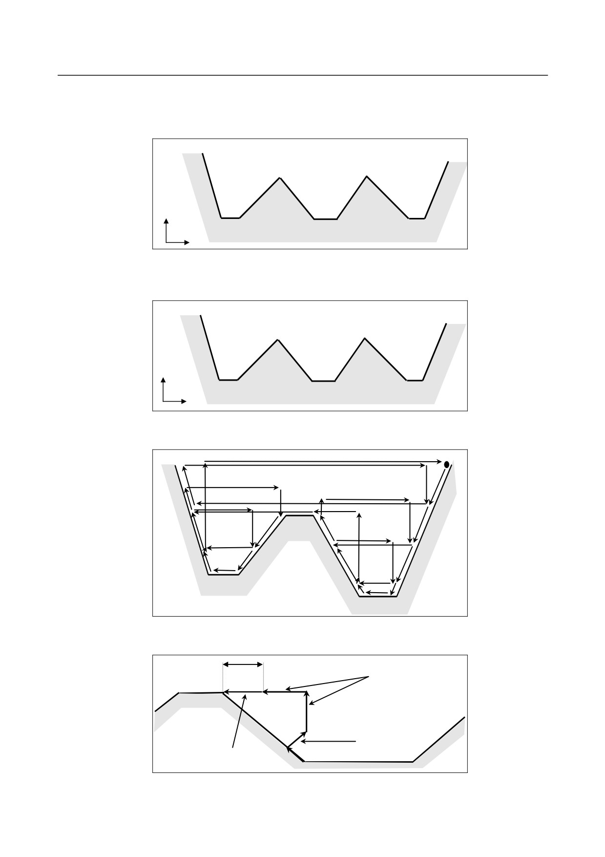
Order and path for rough cutting of pockets
Rough cutting is performed in the following order.
(a) When the figure shows monotone decrease along the first axis on the plane (Z-axis for the ZX
plane)
Rough cutting is performed in the order <1>, <2>, and <3>
from the rightmost pocket.
<3>
<2>
<1>
+X
+Z
Fig. 7.1.1 (m) Rough cutting order in the case of monotone decrease (type II)
(b) When the figure shows monotone increase along the first axis on the plane (Z-axis for the ZX
plane)
Rough cutting is performed in the order <1>, <2>, and <3>
from the leftmost pocket.
<1>
<2>
<3>
+X
+Z
Fig. 7.1.1 (n) Rough cutting order in the case of monotone increase (type II)
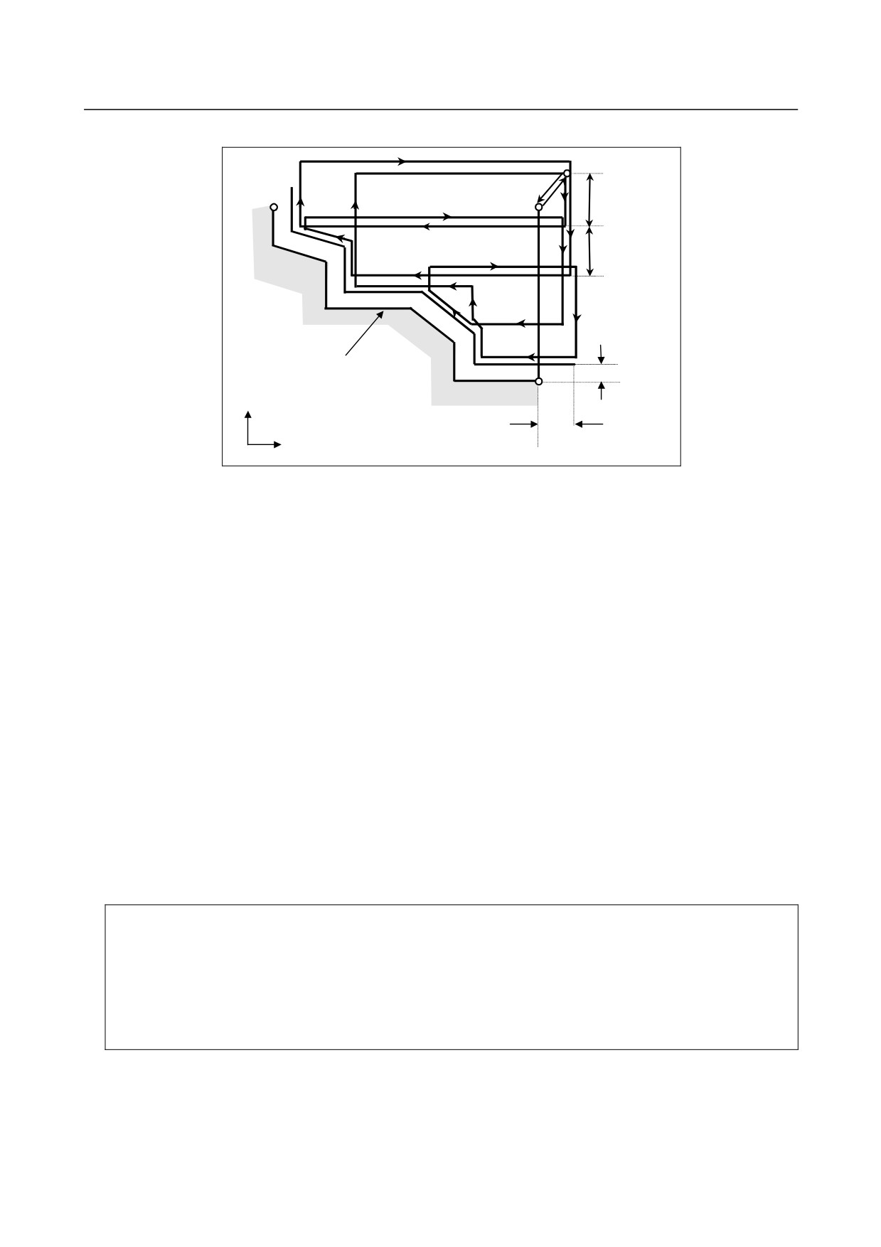
The path in rough cutting is as shown Fig. 7.1.1 (o).
35
4
3
1
34
5
24
9
10
25
2
23
29
22
21
11
6
28
30
8
26
15
27
7
33
31
12
14
20
16
32
13
19
18
17
Fig. 7.1.1 (o) Cutting path for multiple pockets (type II)
The Fig. 7.1.1 (p) shows how the tool moves after rough cutting for a pocket in detail.
g
Rapid traverse
21
22
•
D
20
Escaping from
the bottom
19
Cutting feed
Fig. 7.1.1 (p)
- 290 -
7.MEMORY OPERATION
B-64484EN-2/02
PROGRAMMING
USING Series 15 FORMAT
Cuts the workpiece at the cutting feedrate and escapes to the direction of 45 degrees. (Operation 19)
Then, moves to the height of point D in rapid traverse. (Operation 20)
Then, moves to the position the amount of g before point D. (Operation 21)
Finally, moves to point D in cutting feed.
The clearance g to the cutting feed start position is set in parameter No. 5134.
For the last pocket, after cutting the bottom, the tool escapes to the direction of 45 degrees and returns to
the start point in rapid traverse. (Operations 34 and 35)
CAUTION
1 This CNC differs from the FANUC Series 16i/18i/21i in cutting of a pocket.
The tool first cuts the nearest pocket to the start point. After cutting of the pocket
terminates, the tool moves to the nearest but one pocket and starts cutting.
2 When the figure has a pocket, generally specify a value of 0 for Δw (finishing
allowance). Otherwise, the tool may dig into the wall on one side.
3 This CNC differs from the FANUC Series 16i/18i/21i in the path of cutting after
turning depending on the figure of the workpiece. When the tool becomes
moving only along the first axis on the plane (Z-axis for the ZX plane) according
to the figure of the workpiece during cutting, it starts retraction along the second
axis on the plane (X-axis for the ZX plane).
-
Tool nose radius compensation
When using tool nose radius compensation, specify a tool nose radius compensation command (G41,
G42) before a multiple repetitive canned cycle command (G70.7, G71.7, G72.7, G73.7) and specify the
cancel command (G40) outside the programs (from the block specified with P to the block specified with
Q) specifying a target finishing figure. If tool nose radius compensation is specified in the program
specifying a target finishing figure, alarm PS0325,
“UNAVAILABLE COMMAND IS IN SHAPE
PROGRAM”, is issued.
Program example
G42;
Specify this command before a multiple repetitive canned cycle command.
G71.7P10Q20D10000;
N10G00X0;
:
N20X50.;
G40;
Specify this command after the program specifying a target finishing figure.
When this cycle is specified in the tool nose radius compensation mode, offset is temporarily canceled
during movement to the start point. Start-up is performed in the first block. Offset is temporarily canceled
again at the return to the cycle start point after termination of cycle operation. Start-up is performed again
according to the next move command. This operation is shown in the Fig. 7.1.1 (q).
- 291 -