FANUC Series 30i-MODEL B, 31i-MODEL B, 32i-MODEL B. For Machining Center System. OPERATOR'S MANUAL - page 8
6.COMPENSATION FUNCTION
PROGRAMMING
B-64484EN-2/02
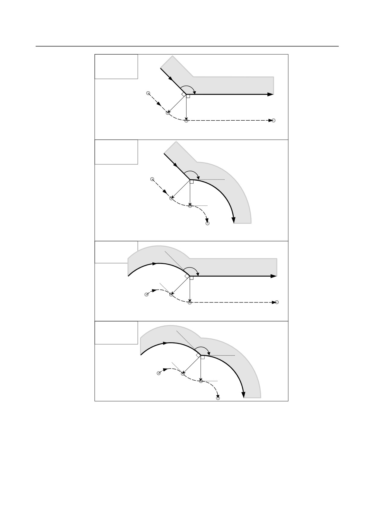
Linear→Linear
(Circular
connection type)
α
Workpiece
L
r
Programmed path
r
C
S
L
Tool center path
Linear→Circular
(Circular
connection type)
α
r
Work-
L
r
piece
C
S
C
Tool center path
Programmed path
Circular→Linear
(Circular
connection type)
α
Workpiece
Programmed path
r
r
C
C
S
L
Tool center path
Circular→Circular
(Circular
connection type)
α
Programmed path
r
Work-
r
piece
C
Tool center path
C
S
C
- 202 -
B-64484EN-2/02
PROGRAMMING
6.COMPENSATION FUNCTION
-
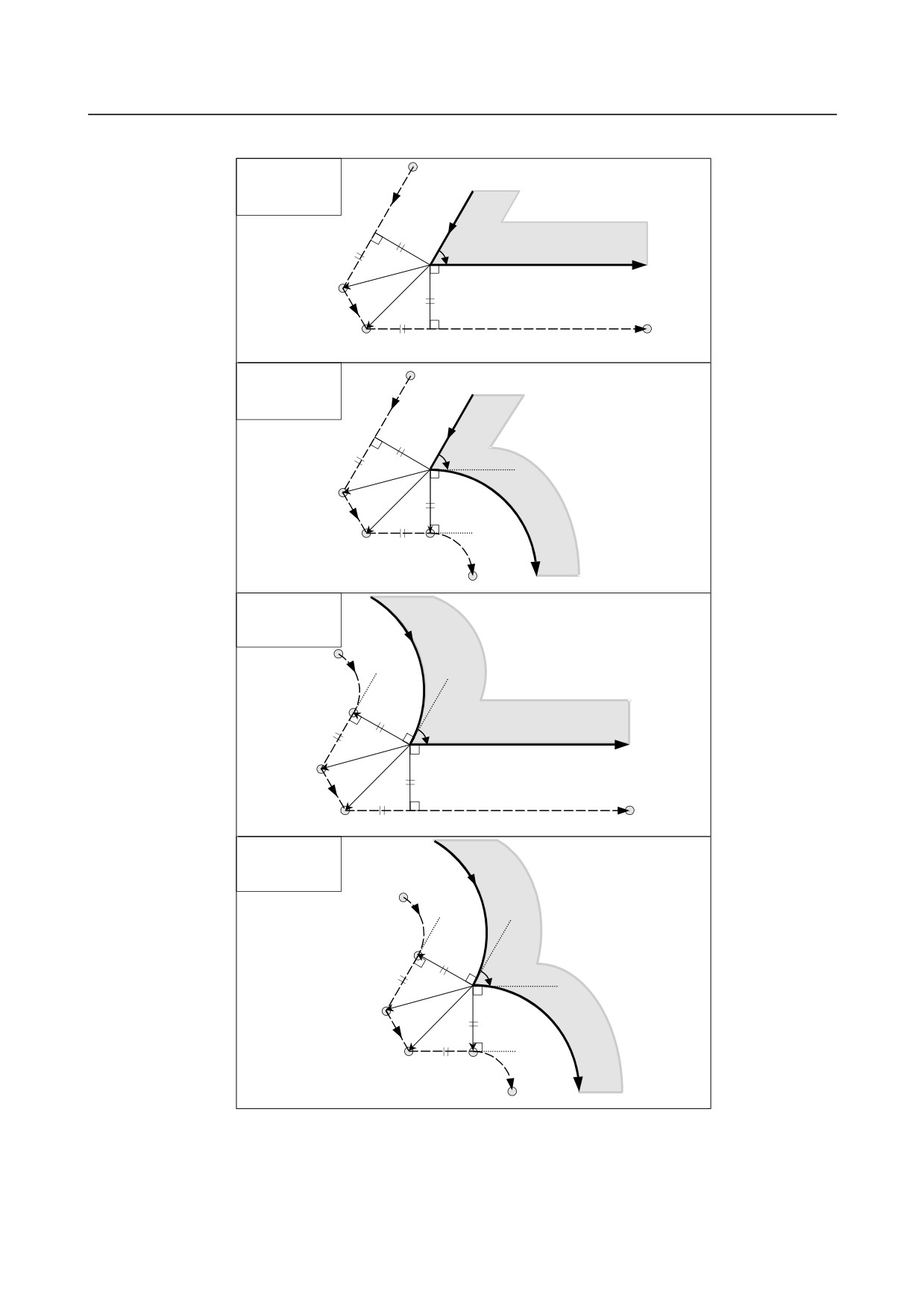
Tool movement around the outside corner at an acute angle (α<90°)
Linear→Linear
(Linear
connection type)
L
Workpiece
α
r
L
Programmed path
r
L
S
L
L
Tool center path
Linear→Circular
(Linear
connection type)
L
r
α
L
Work-
r
piece
L
S
L
C
Programmed path
Tool center path
Circular→Linear
(Linear
connection type)
C
Workpiece
r
α
L
Programmed path
r
L
S
L
L
Tool center path
Circular→Circular
(Linear
connection type)
C
r
α
L
Work-
r
piece
L
S
L
C
Tool center path
Programmed path
- 203 -
6.COMPENSATION FUNCTION
PROGRAMMING
B-64484EN-2/02
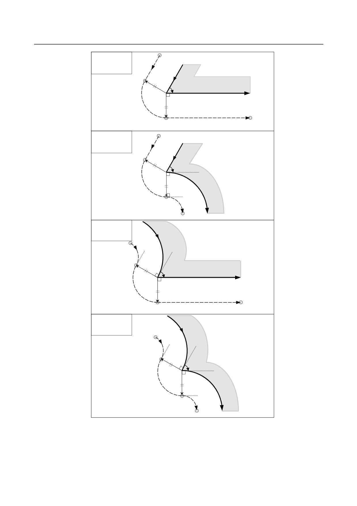
Linear→Linear
(Circular
connection type)
L
Workpiece
r
α
Programmed path
r
C
S
L
Tool center path
Linear→Circular
(Circular
connection type)
L
α
r
r
Work-
piece
C
S
C
Programmed path
Tool center path
Circular→Linear
(Circular
connection type)
C
Workpiece
r
α
Programmed path
r
C
S
L
Tool center path
Circular→Circular
(Circular
connection type)
C
r
α
Work-
r
piece
C
S
C
Tool center path
Programmed path
- 204 -

B-64484EN-2/02
PROGRAMMING
6.COMPENSATION FUNCTION
-
When it is exceptional
End point for the arc is not on the arc
If the end of a line leading to an arc is not on the arc, the system assumes that the cutter compensation has
been executed with respect to an imaginary circle that has the same center as the arc and passes the
specified end point. Based on this assumption, the system creates a vector and carries out compensation.
The same description applies to tool movement between two circular paths.
End the arc
Work-
piece
Imaginary circle
Programmed path
r
r
Tool center path
r
C
L
L
Center of the arc
L S
There is no inner intersection
If the tool radius / tool nose radius compensation value is sufficiently small, the two circular tool center
paths made after compensation intersect at a position (P). Intersection P may not occur if an excessively
large value is specified for tool radius ⋅ tool nose radius compensation. When this is predicted, PS0033
occurs at the end of the previous block and the tool is stopped.
For example, tool center paths along arcs A and B intersect at P when a sufficiently small value is
specified for tool radius ⋅ tool nose radius compensation. If an excessively large value is specified, this
intersection does not occur.
Alarm occurs and the tool stops
When the cutter or tool nose radius
compensation value is large
When the cutter or tool nose radius
compensation value is small
Center of the arc B
Center of the arc A
Programmed path
r
r
Arc A
Arc B
P
- 205 -
6.COMPENSATION FUNCTION
PROGRAMMING
B-64484EN-2/02
-
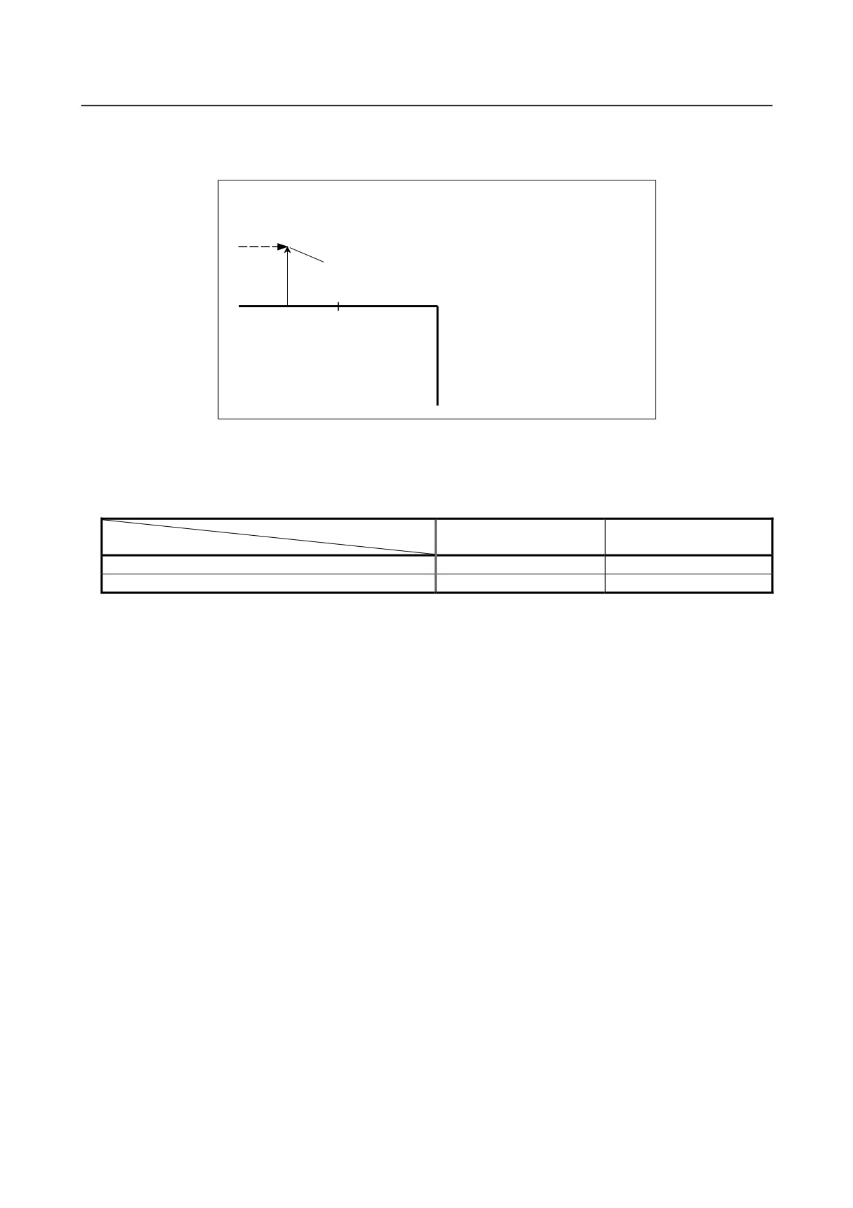
When the center of the arc is identical with the start point or the end point
If the center of the arc is identical with the start point or end point, PS0041 is displayed, and the tool will
stop at the start point of the preceding block of the arc.
(G41)
N5 G91 G01 X50.0 ;
Tool center path
N6 X50.0 ;
N7 G02 X100.0 I0 J0 ;
Alarm is displayed and the
N8 G01 Y-100.0 ;
tool stops
N5
N6
N7
Programmed path
N8
-
Change in the offset direction in the offset mode
The offset direction is decided by G codes (G41 and G42) for tool radius ⋅ tool nose radius compensation
and the sign of the compensation value as follows.
Sign of compensation
+
-
G code
G41
Left side offset
Right side offset
G42
Right side offset
Left side offset
The offset direction can be changed in the offset mode. If the offset direction is changed in a block, a
vector is generated at the intersection of the tool center path of that block and the tool center path of a
preceding block.
However, the change is not available in the start-up block and the block following it.
- 206 -
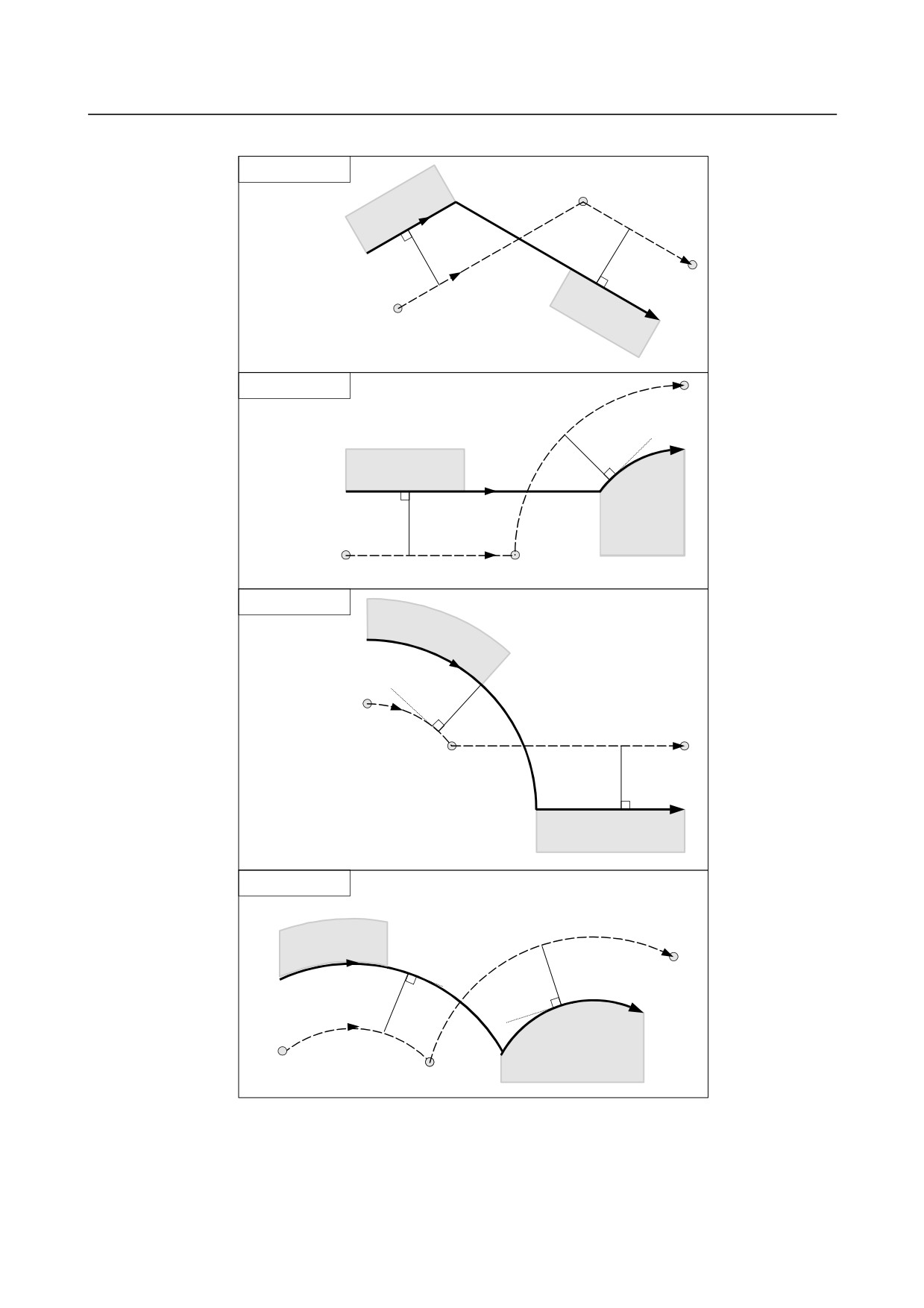
B-64484EN-2/02
PROGRAMMING
6.COMPENSATION FUNCTION
-
Tool center path with an intersection
Linear→Linear
Workpiece
S
G42
L
Intersection
r
r
Programmed path
L
G41
Tool center path
Workpiece
Linear→Circular
C
r
Workpiece
G41
G42
Programmed path
r
Workpiece
Intersection
Tool center path
L
S
Circular→Linear
Workpiece
G42
Programmed path
r
Tool center path
C
L
S
Intersection
r
G41
Workpiece
Circular→Circular
C
Workpiece
G42
r
Programmed path
r
G41
C
Tool center path
Workpiece
S
Intersection
- 207 -
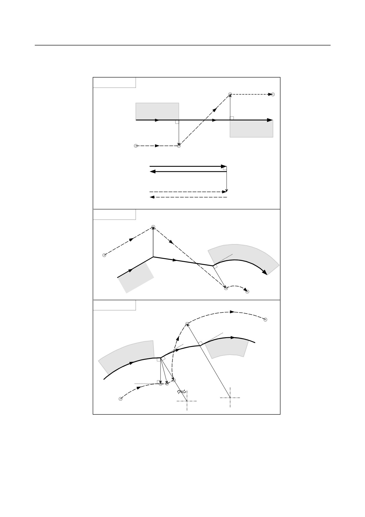
6.COMPENSATION FUNCTION
PROGRAMMING
B-64484EN-2/02
-
Tool center path without an intersection
When changing the offset direction in block A to block B using G41 and G42, if intersection with the
offset path is not required, the vector normal to block B is created at the start point of block B.
Linear→Linear
S
L
W orkpiece
r
(G42)
Programmed path
G42
G41
B
A
L
W orkpiece
r
Tool center path
L
S
G42
Programmed path
G41
r
Tool center path
S
L
Linear→Circular
Intersection
S
L
L
Tool center path
A
(G41)
B
G42
(G41)
r
Programmed path
S
Circular→Circular
C
S
An arc whose end position
r
is not on the arc
C
G41
(G42)
Programmed path
(G42)
r
r
L
C
L
S
Center
Center
Tool center path
-
The length of tool center path larger than the circumference of a circle
Normally there is almost no possibility of generating this situation. However, when G41 and G42 are
changed, or when a G40 was commanded with address I, J, and K this situation can occur.
- 208 -
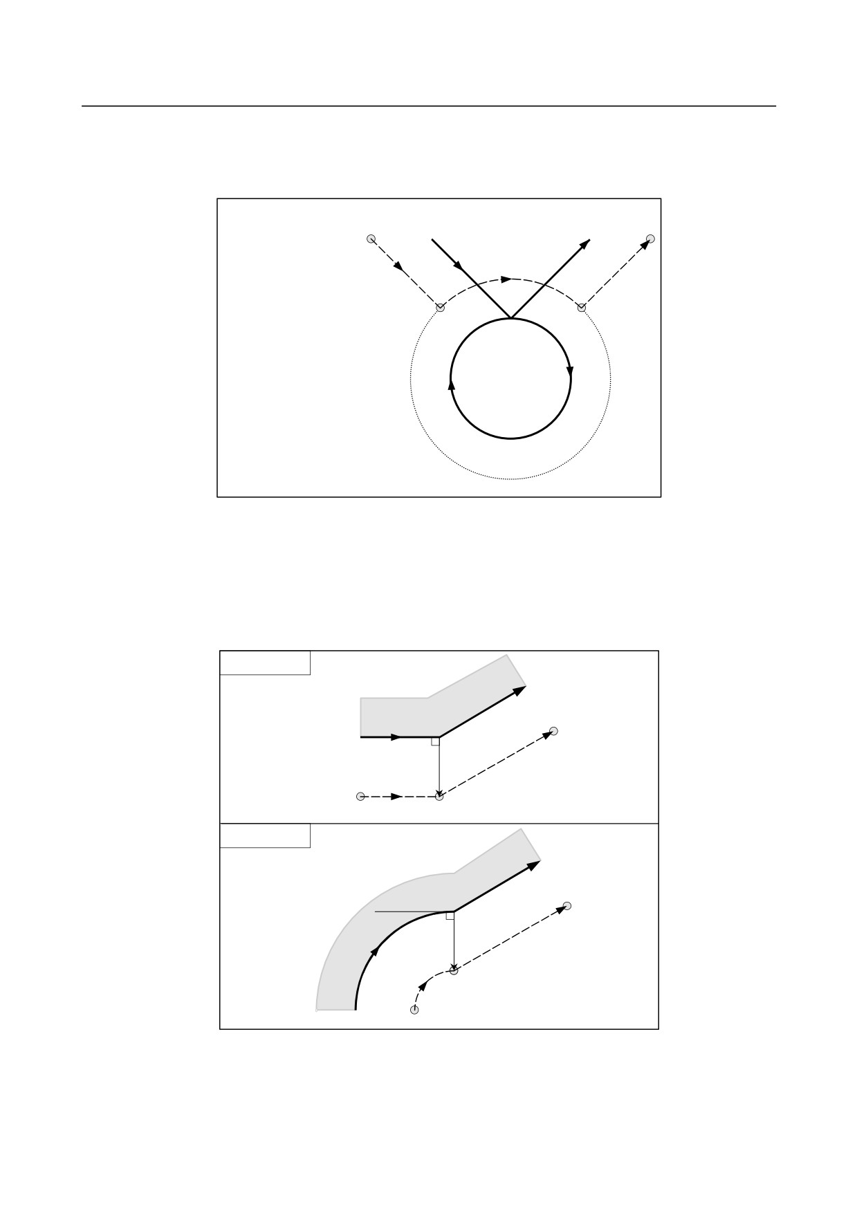
B-64484EN-2/02
PROGRAMMING
6.COMPENSATION FUNCTION
The cutter compensation is not performed with more than one circle circumference: an arc is formed from
P1 to P2 as shown. Depending on the circumstances, an alarm may be displayed due to the "Interference
Check" described later. To execute a circle with more than one circumference, the circle must be
specified in segments.
Tool center path Programmed path
N5
N7
P1
P2
(G42)
N5 G01 G91 X500.0 Y-700.0 ;
N6
N6 G41 G02 J-500.0 ;
N7 G42 G01 X500.0 Y700.0 ;
-
Cutter compensation G code in the offset mode
The offset vector can be set to form a right angle to the moving direction in the previous block,
irrespective of machining inner or outer side, by commanding the cutter compensation G code (G41, G42)
in the offset mode, independently. If this code is specified in a circular command, correct circular motion
will not be obtained.
When the direction of offset is expected to be changed by the command of cutter compensation G code
(G41, G42), see "Change in the offset direction in the offset mode".
Linear→Linear
A block specified by G42
G42 mode
r
L
L
Tool center path
S
Intersection
Circular→Linear
A block specified by G42
r
G42 mode
L
C
S
Intersection
Programmed path
-
Command canceling the offset vector temporarily
During offset mode, if G92 (workpiece coordinate system setting) or G52 (local coordinate system
setting) is commanded, the offset vector is temporarily cancelled and thereafter offset mode is
automatically restored.
- 209 -
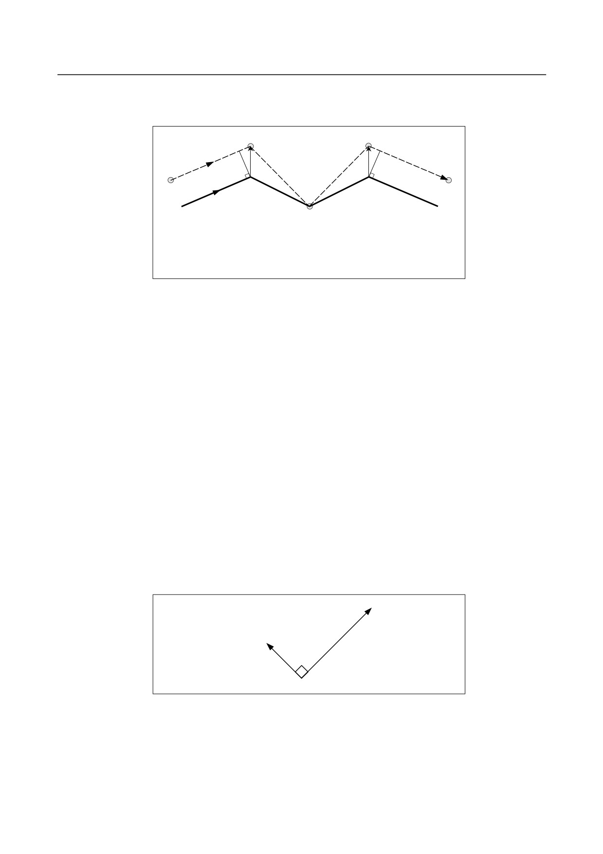
6.COMPENSATION FUNCTION
PROGRAMMING
B-64484EN-2/02
In this case, without movement of offset cancel, the tool moves directly from the intersecting point to the
commanded point where offset vector is canceled.
Also when restored to offset mode, the tool moves directly to the intersecting point.
S
S
L
L
L
L
Tool center path
S
N5
N6
N8
Programmed path
N7
G92 block
(G41)
N5 G01 X700.0 Y300.0 ;
N6 X600.0 Y-300.0 ;
N7 G92 X200.0 Y100.0 ;
N8 G01 X800.0 Y400.0 ;
Before specifying G28 (reference position return), G29 (movement from reference position), G30 (second,
third, and fourth reference position return), G30.1 (floating reference position return), and G53 (machine
coordinate system selection) commands, cancel offset mode, using G40. If an attempt is made to specify
any of the commands in offset mode, the offset vector temporarily disappears.
-
If I, J, and K are specified in a G00/G01 mode block
At the start of cutter compensation or in that mode, by specifying I, J, and K in a positioning mode (G00)
or linear interpolation mode (G01) block, it is possible to set the compensation vector at the end point of
that block in the direction vertical to that specified by I, J, and K. This makes it possible to change the
compensation direction intentionally.
IJ type vector (XY plane)
The following explains the compensation vector (IJ type vector) to be created on the XY compensation
plane (G17 mode). (The same explanation applies to the KI type vector on the G18 plane and the JK type
vector on the G19 plane.) It is assumed that the compensation vector (IJ type vector) is the vector with a
size equal to the compensation value and vertical to the direction specified by I and J, without performing
intersection calculation on the programmed path. I and J can be specified both at the start of cutter
compensation and in that mode. If they are specified at the start of compensation, any start-up type set in
the appropriate parameter will be invalid, and an IJ type vector is assumed.
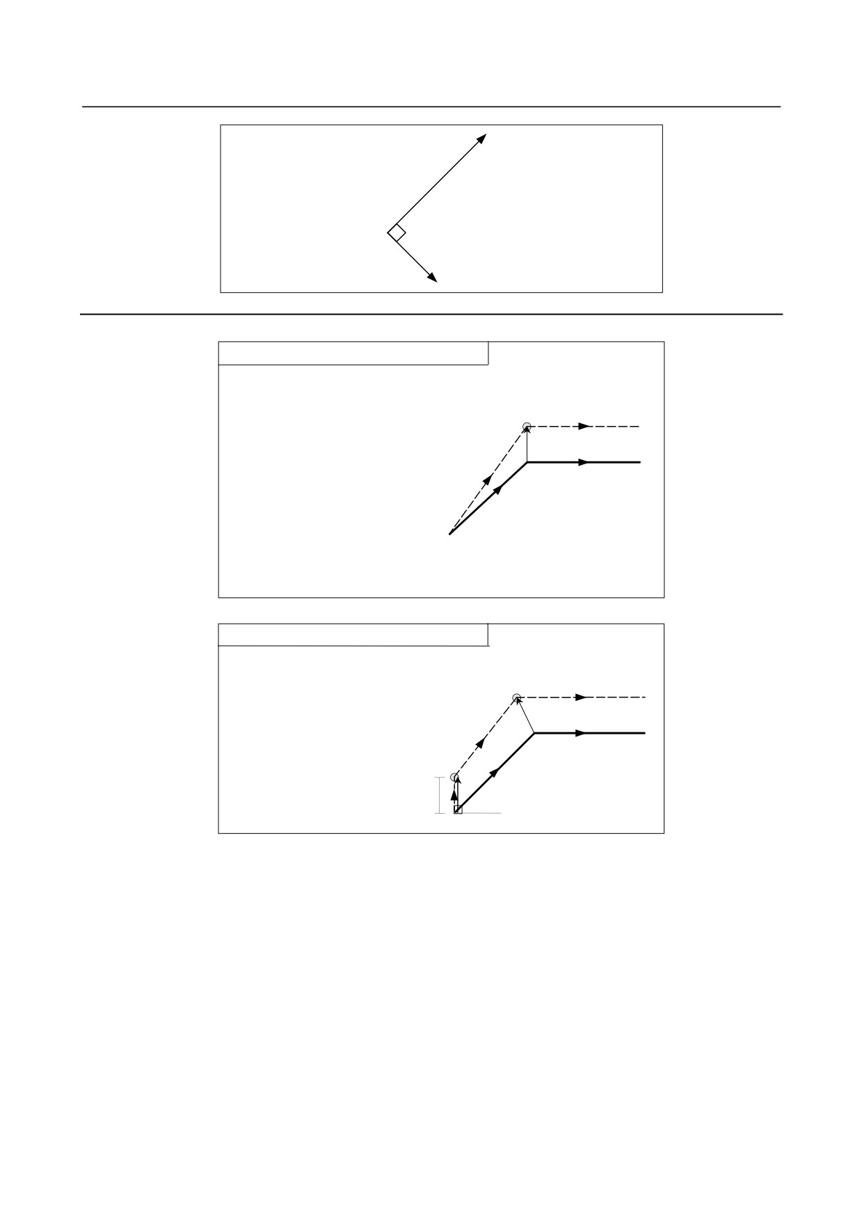
Offset vector direction
In G41 mode, the direction specified by I, J, and K is assumed an imaginary tool movement direction, and
an offset vector is created vertical to that direction and on the left side.
Compensation vector
I, J, K
In G42 mode, the direction specified by I, J, and K is assumed an imaginary tool movement direction, and
an offset vector is created vertical to that direction and on the right side.
- 210 -
B-64484EN-2/02
PROGRAMMING
6.COMPENSATION FUNCTION
I, J, K
Compensation vector
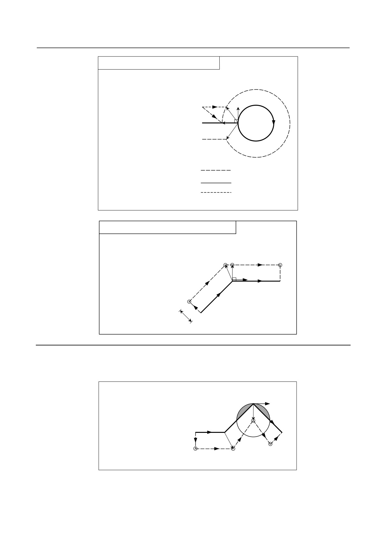
Example
If I and J are specified at the start of compensation (with
tool movement)
N50
N40
(G40)
N30
N10 G91 G41 X100.0 Y100.0
N20
N60
I1 D1 ;
N20 G04 X1000 ;
D1
Tool center path
N30 G01 F1000 ;
N10
N40 S300 ;
N50 M50 ;
Programmed path
N60 X150. ;
Note) In N10, a vector is
specified with a size of D1
in the direction vertical to
the X axis, using I1.
If I and J are specified at the start of compensation
(without tool movement)
(G40)
N30
N10 G41 I1 D1 ;
N20 G91 X100. Y100. ;
Tool nose radius
N30 X150. ;
center path
N20
Note) In N10, a vector is
Programmed path
specified with a size
of D1 in the direction
N10
vertical to the X axis,
using I1.
D1
- 211 -
6.COMPENSATION FUNCTION
PROGRAMMING
B-64484EN-2/02
If I and J are specified at the start of compensation (with
tool movement)
(G17 G41 G91 D1)
N10 G00 X150. J50. ;
N20 G02 I50. ;
(I,J)
N30 G00 X-150. ;
<2>
Note) In N10, a vector is specified
N10
N20
with a size of D1 in the
N30
direction vertical to the Y axis,
<1>
<2>
using J50.
<1> IJ type vector
<2> Vector determined with
intersection calculation
Tool center path
Programmed path
Path determined with
intersection calculation
If I and J are specified in a block without tool movement in
compensation mode
N30
N40
Tool center
S S
path
Start-up/cancel type C
N20
N50
N10 G41 D1 G01 F1000 ;
(I, J)
N20 G91 X100. Y100. ;
Programmed path
N30 I10. ;
N40 X150. ;
N50 G40 ;
N10
D1
Limitation
If an IJ type vector is specified, tool interference may occur due to that vector alone, depending on the
direction. If this occurs, no interference alarm will occur, or no interference avoidance will be performed.
Overcutting may, therefore, result.
Overcutting
(I, J)
Start-up/cancel
Type C
N40
N30
Programmed
N10 G42 D1 F1000 ;
N20
path
N20 G91 X100. ;
N30 X100. Y-100. I10. ;
N50
N10
N40 X100. Y-100. ;
N50 G40 ;
Tool center path
-
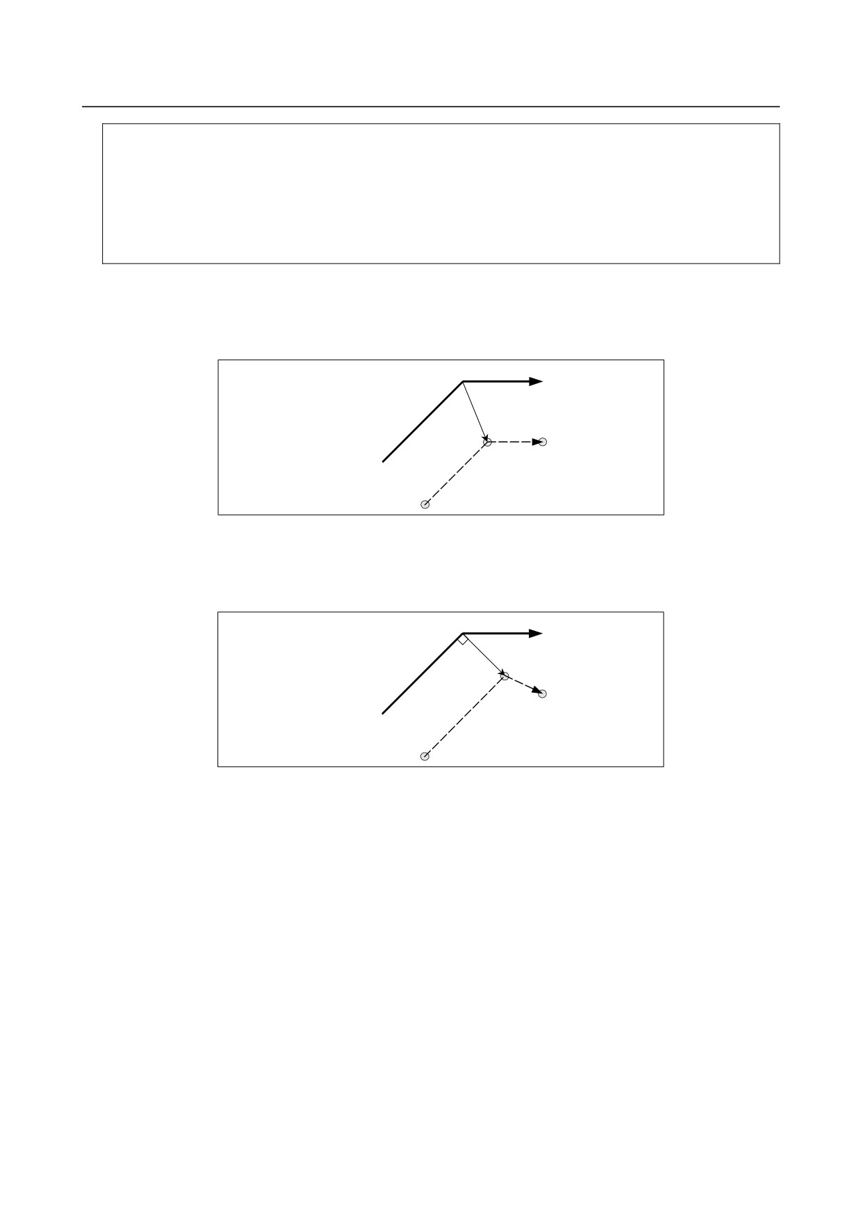
A block without tool movement
The following blocks have no tool movement. In these blocks, the tool will not move even if cutter
compensation is effected.
- 212 -
B-64484EN-2/02
PROGRAMMING
6.COMPENSATION FUNCTION
M05 ;
:
M code output
S21 ;
:
S code output
G04 X10.0 ;
:
Dwell
G22 X100000 ;
:
Machining area setting
G10 L11 P01 R10.0 ;
:
Cutter compensation value setting/changing
(G17) Z200.0 ;
:
Move command not included in the offset plane.
G90 ;, O10 ;, N20 ;
:
G, O, and N codes only
G91 X0 ;
:
Move distance is zero.
-
A block without tool movement specified in offset mode
Unless the number of blocks without movement consecutively specified is more than N-2 blocks (where
N is the number of blocks to read in offset mode (parameter No. 19625)) in offset mode, the vector and
the tool center path will be as usual. This block is executed at the single block stop point.
N6 G91 X100.0 Y100.0 ;
N7
N8
Programmed path
N7 G04 X10.0 ;
N8 X100.0 ;
N6
L
Tool center path
SS
L
Block N7 is executed here.
In offset mode, the number of blocks without movement consecutively specified must not exceed N-2
(where N is the number of blocks to read in offset mode (parameter No. 19625). If commanded, a vector
whose length is equal to the offset value is produced in a normal direction to tool motion in earlier block,
so overcutting may result.
N6 G91 X100.0 Y100.0 ;
N7,N8
N9
N7 S21 ;
Programmed path
N8 G04 X10.0 ;
N9 X100.0 ;
N6
(No. of blocks to read in
offset mode = 3)
L
Tool center path
SSS
L Blocks N7 and N8 are executed here.
-
If an M/G code that suppresses buffering is specified
If an M/G code that suppresses buffering is specified in offset mode, it is no longer possible to read and
analyze subsequent blocks regardless of the number of blocks to read in offset mode, which is determined
by parameter No. 19625. Then, intersection calculation and a interference check, described later, are no
longer possible. If this occurs, overcutting may occur because a vertical vector is output in the
immediately preceding block.
- 213 -
6.COMPENSATION FUNCTION
PROGRAMMING
B-64484EN-2/02
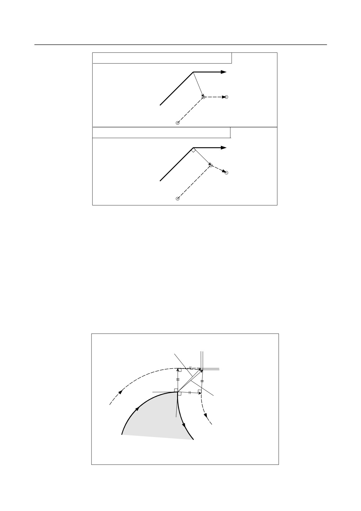
If an M code (M50) that suppresses buffering is not specified
(G42)
N6
Programmed path
N5 G91 G01 X40.0 Y40.0 ;
N6 X40.0 ;
:
:
N5
L
Tool center path
S
L
Intersection
If an M code (M50) that suppresses buffering is specified
(G42)
N6
N7
Programmed path
N5 G91 G01 X40.0 Y40.0 ;
N6 M50 ;
N7 X40.0 ;
N5
:
L
:
Tool center path
SS
L
Block N6 is executed here.
-
Workpiece coordinate system or local coordinate system command in the
offset mode
If the local coordinate system (G52) or workpiece coordinate system (G92) is specified in the cutter
compensation (G41 or G42) or 3-dimensional cutter compensation (G41.2 to G41.6 or G42.2 to G42.6)
mode, G52 or G92 is assumed to be a buffering masked G code. The subsequent blocks are not executed
until the G52 or G92 block is executed.
-
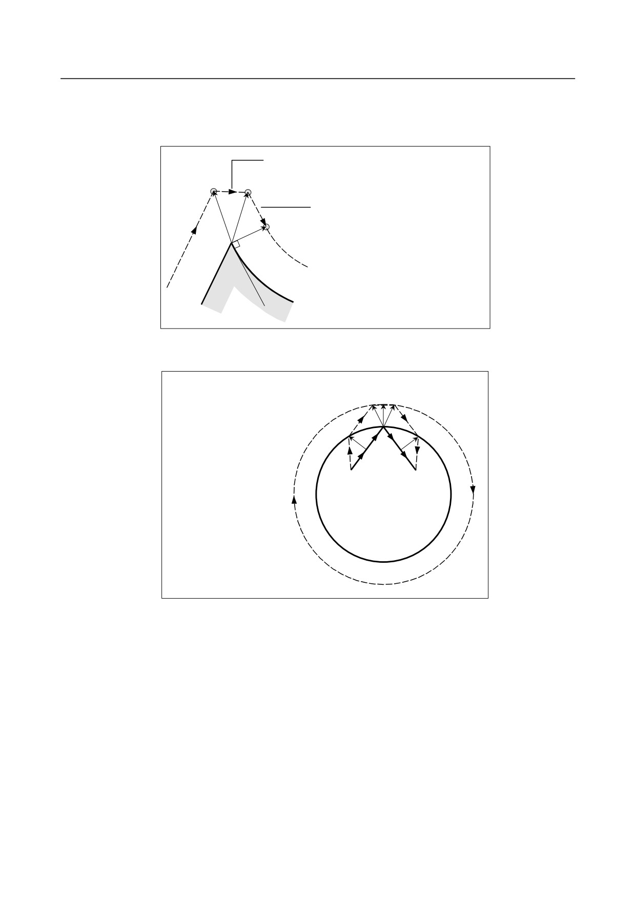
Corner movement
When two or more offset vectors are produced at the end of a block, the tool moves linearly from one
vector to another. This movement is called the corner movement.
If these vectors almost coincide with each other (the distance of corner movement between the vectors is
judged short due to the setting of parameter No. 5010), corner movement is not performed. In this case,
the vector to the single block stop point takes precedence and remains, while other vectors are ignored.
This makes it possible to ignore the very small movements arising from performing cutter compensation,
thereby preventing velocity changes due to interruption of buffering.
ΔVX
This vector is ignored, if
ΔVX ≤ ΔVlimit and
ΔVY ≤ ΔVlimit
ΔVY
r
S
r
The vector to the single block
stop point remains even if
N1
ΔVX ≤ ΔVlimit and ΔVY ≤ Vlimit.
N1
Tool center path
N2
Programmed path
ΔVlimit is determined with the setting of parameter (No. 5010).
- 214 -
B-64484EN-2/02
PROGRAMMING
6.COMPENSATION FUNCTION
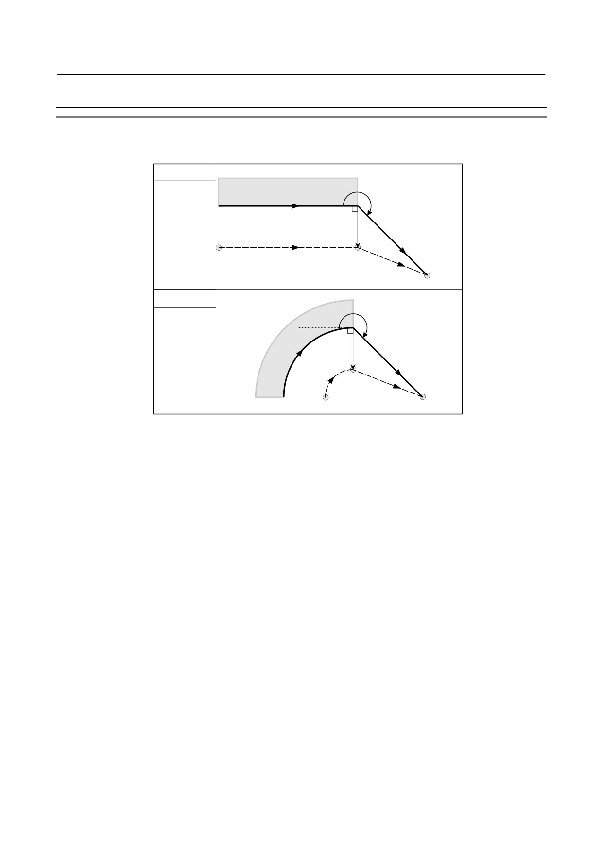
If the vectors are not judged to almost coincide (therefore, are not erased), movement to turn around the
corner is performed. The corner movement that precedes the single block stop point belongs to the
previous block, while the corner movement that succeeds the single block stop point belongs to the latter
block.
This move belongs to block N6, thus, the feedrate is equal
to that in block N6.
S
This move belongs to block N7, thus, the
feedrate is equal to that in block N7.
N6
N7
However, if the path of the next block is semicircular or more, the above function is not performed.
The reason for this is as follows:
P2 P3 P4 P5
N4 G41 G91 G01 X150.0 Y200.0 ;
N5 X150.0 Y200.0 ;
N6 G02 J-600.0 ;
N7 G01 X150.0 Y-200.0 ;
P1
P6
N8 G40 X150.0 Y-200.0 ;
N5 N7
N4
N8
N6
Programmed path
Tool center path
If the vector is not ignored, the tool path is as follows:
P1 → P2 → P3 → (Circle) → P4 → P5 → P6
But if the distance between P2 and P3 is negligible, the point P3 is ignored. Therefore, the tool path is as
follows:
P2 → P4
Namely, circle cutting by the block N6 is ignored.
-
Interruption of manual operation
For manual operation during the offset mode, see "Manual Absolute ON and OFF."
- 215 -
6.COMPENSATION FUNCTION
PROGRAMMING
B-64484EN-2/02
6.6.4
Tool Movement in Offset Mode Cancel
Explanation
-
If the cancel block is a block with tool movement, and the tool moves around
the inside (180° ≤ α)
Linear→Linear
Workpiece
α
Programmed path
r
G40
L
S
Tool center path
L
Circular→Linear
α
Work-
piece
r
G40
S
C
L
Programmed path
Tool center path
- 216 -
B-64484EN-2/02
PROGRAMMING
6.COMPENSATION FUNCTION
-
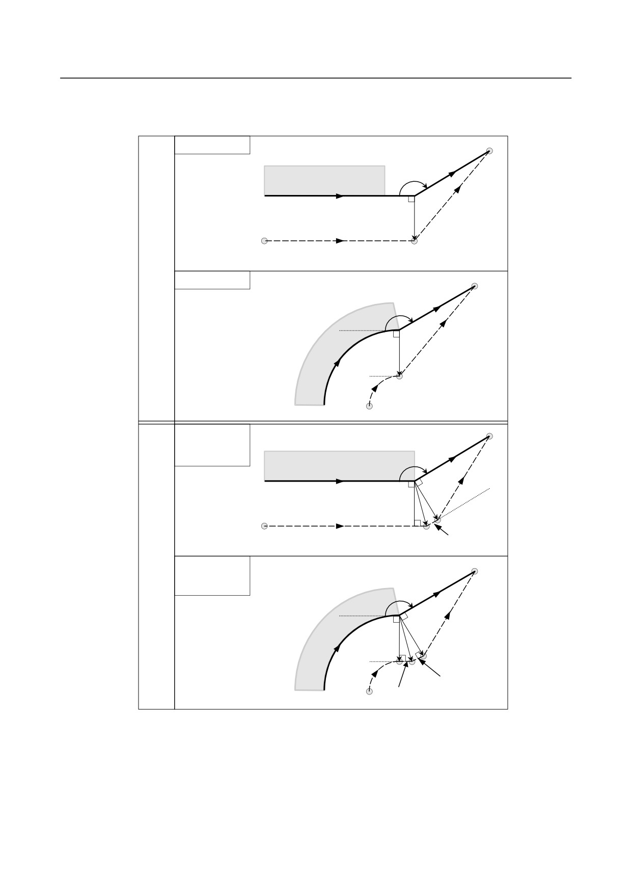
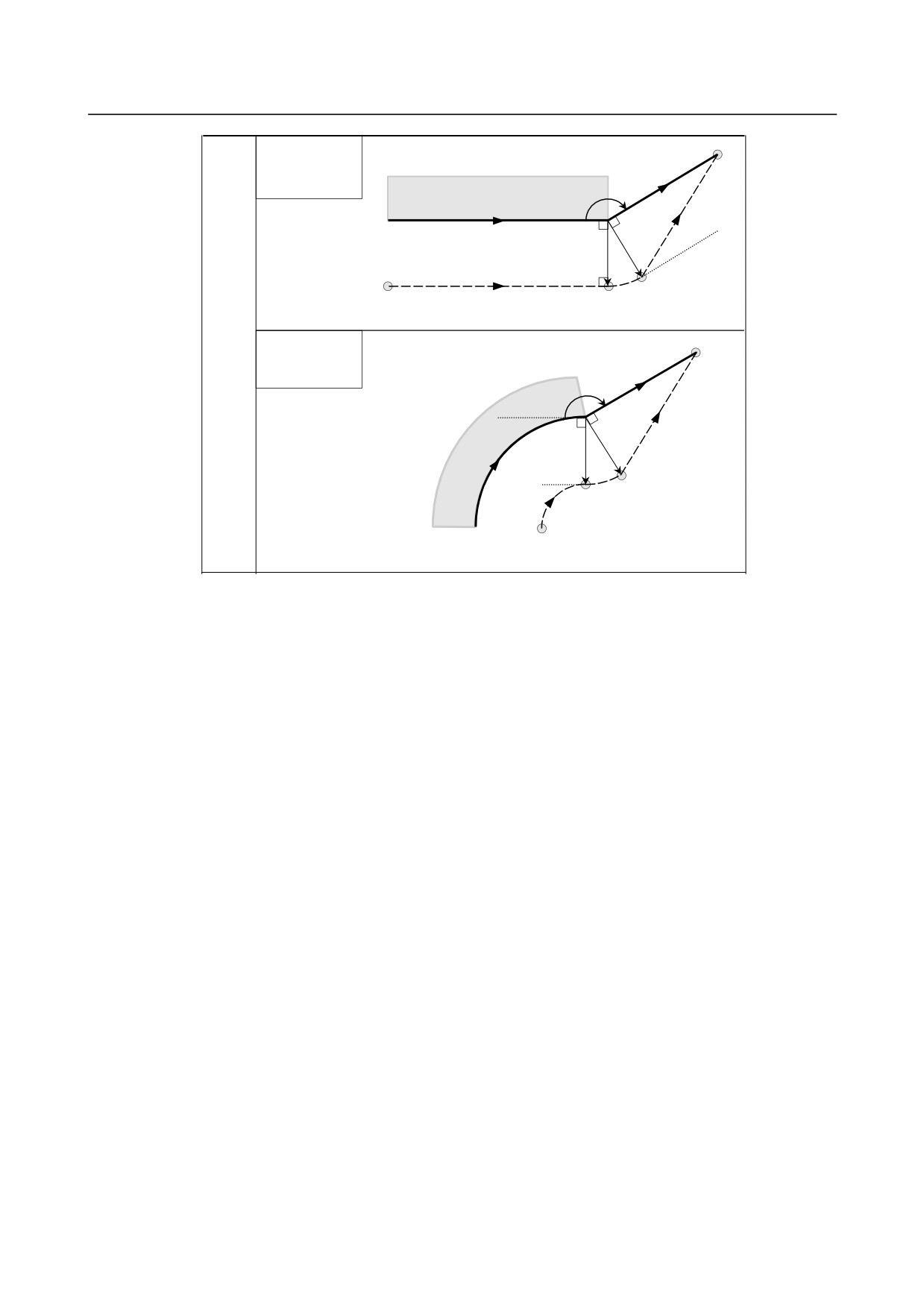
If the cancel block is a block with tool movement, and the tool moves around
the outside at an obtuse angle (90° ≤ α < 180°)
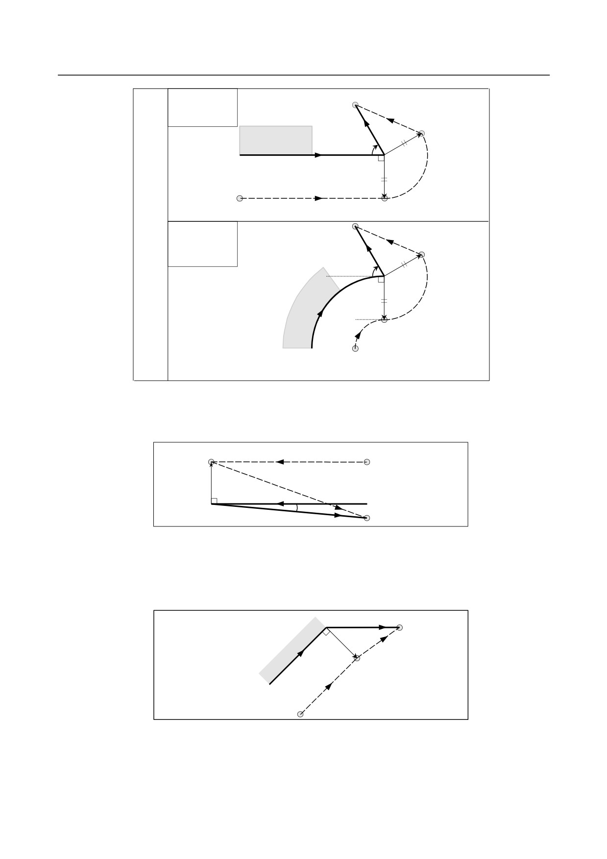
Tool path has two types A and B, and they are selected by bit 0 (SUP) of parameter No. 5003.
Linear→Linear
G40
Workpiece
α
Programmed path
L
r
Tool center path L
S
Type
A
Circular→Linear
G40
α
L
Work-
piece
r
S
C
Programmed path
Tool center path
Linear→Linear
(Linear
connection type)
G40
Workpiece
α
L
Programmed path
r
Tool center path
Intersection
L
S
Type
B
Circular→Linear
(Linear
connection type)
G40
α
L
Work-
r
piece
r
S
C
Inter-
L
section
L
Programmed path
Tool center path
- 217 -
6.COMPENSATION FUNCTION
PROGRAMMING
B-64484EN-2/02
Linear→Linear
(Circular
connection type)
G40
Workpiece
α
L
Programmed path
r
C S
Tool center path
Type
B
Circular→Linear
(Circular
connection type)
G40
α
L
Work-
r
piece
r
C S
C
Programmed path
Tool center path
- 218 -

B-64484EN-2/02
PROGRAMMING
6.COMPENSATION FUNCTION
-
If the cancel block is a block with tool movement, and the tool moves around
the outside at an acute angle (α<90°)
Tool path has two types A and B, and they are selected by bit 0 (SUP) of parameter No. 5003.
Linear→Linear
G40
W orkpiece
L
α
Programmed path
G42
r
Tool center path
L
S
Type
A
Circular→Linear
G40
L
α
W ork-
r
piece
G42
S
C
Tool center path
Programmed path
Linear→Linear
(Linear
connection type)
L
W orkpiece
G40
α
r
L
Programmed path
S
r
L
Tool center path
L
L
Type
B
Circular→Linear
L
(Linear
connection type)
α
r
L
S
W ork-
r
piece
L
L
C
Tool center path
Programmed path
- 219 -
6.COMPENSATION FUNCTION
PROGRAMMING
B-64484EN-2/02
Linear→Linear
(Circular
connection type)
L
S
Workpiece
G40
α
r
Programmed path
r
C
Tool center path
L
Type
B
Circular→Linear
L
(Circular
connection type)
S
α
r
C
Work-
r
piece
C
S
Tool center path
Programmed path
-
If the cancel block is a block with tool movement, and the tool moves around
the outside at an acute angle of 1 degree or less in a linear → linear manner
(α≤1°)
S
Tool center path
L
r
L
Programmed path
(G42)
1° or less
G40
-
A block without tool movement specified together with offset cancel
For types A and B
In the block preceding the cancel block, a vector is created with a size equal to the tool radius ⋅ tool
nose radius compensation value in the vertical direction. The tool does not operate in the cancel
block. The remaining vectors are canceled with the next move command.
N6 G91 X100.0 Y100.0 ;
N7
N8
N7 G40 ;
N8 X130.0 ;
N6
L
Programmed path
SS
L
Tool center path
- 220 -
B-64484EN-2/02
PROGRAMMING
6.COMPENSATION FUNCTION
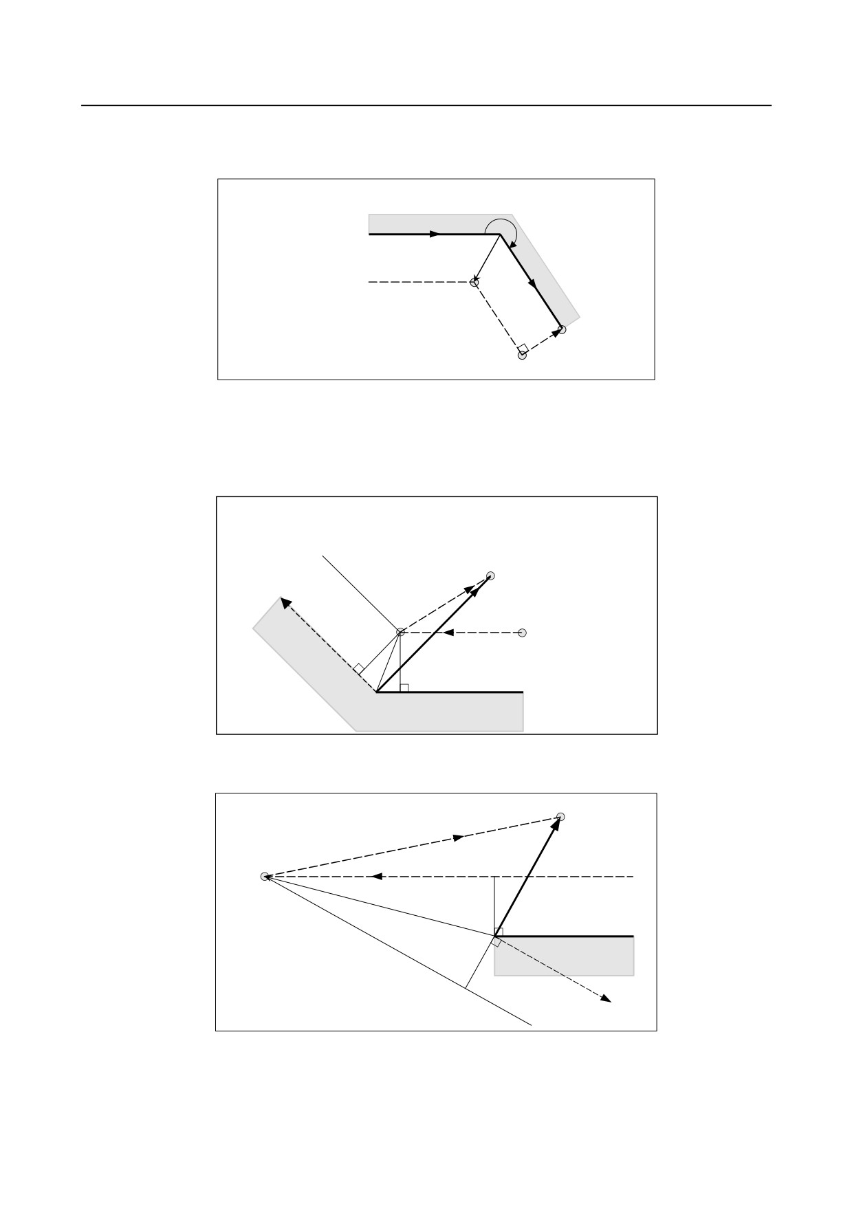
For type C
The tool shifts by the compensation value in the direction vertical to the block preceding the cancel
block.
α
Programmed path
Tool center path
S
G40 (without
movement)
L
L
S
-
Block containing G40 and I_J_K_
The previous block contains G41 or G42
If a G41 or G42 block precedes a block in which G40 and I_, J_, K_ are specified, the system assumes
that the path is programmed as a path from the end point determined by the former block to a vector
determined by (I,J), (I,K), or (J,K). The direction of compensation in the former block is inherited.
N1 (G42 mode) ;
In the N1 block, the tool nose radius center moves
towards P.
N2 G40 Xa Yb I_ J_ ;
In the N2 block, the tool nose radius moves towards E.
E(a, b)
(I, J)
G40
N2
P
Tool center path
S
N1
r
r
(G42) Programamed path
Workpiece
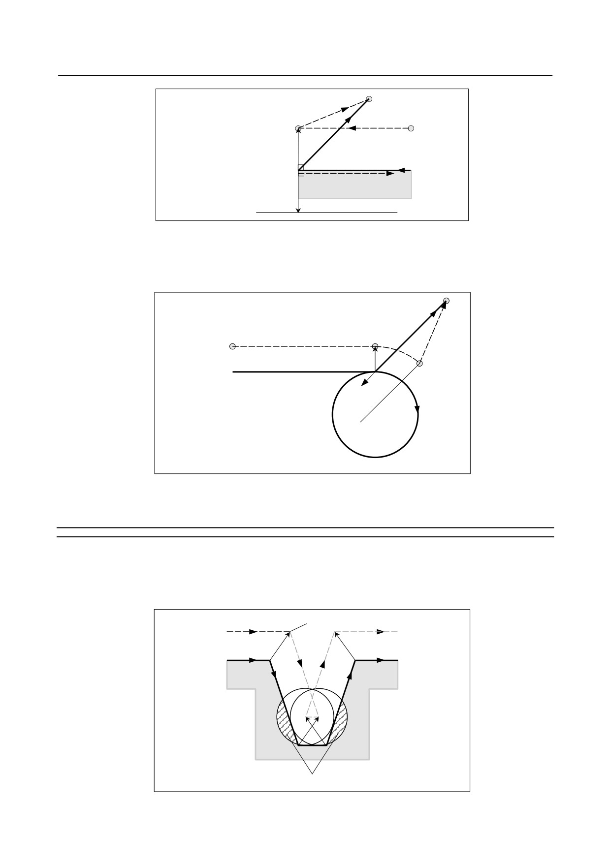
In this case, note that the CNC obtains an intersection of the tool path irrespective of whether inner or
outer side machining is specified.
E
G40
P
Tool center path
S
r
Programmed path
(G42)
r
(I, J)
When an intersection is not obtainable, the tool comes to the normal position to the previous block at the
end of the previous block.
- 221 -
6.COMPENSATION FUNCTION
PROGRAMMING
B-64484EN-2/02
E
P
G40
Tool center path
S
r
(G42) Programmed path
(I, J)
r
-
Length of the tool center path larger than the circumference of a circle
In the Example shown below, the tool does not trace the circle more than once. It moves along the arc
from P1 to P2. The interference check function described below may raise an alarm.
To make the tool trace a circle more than once, program two or more arcs.
P1
Tool center path
P2
Programmed path
N7
N5
(I, J)
N6
(G41)
N5 G01 G91 X100.0 ;
N6 G02 J-60.0 ;
N7 G40 G01 X50.0 Y50.0 I-10.0 J-10.0 ;
6.6.5
Prevention of Overcutting Due to Tool Radius / Tool Nose
Radius Compensation
Explanation
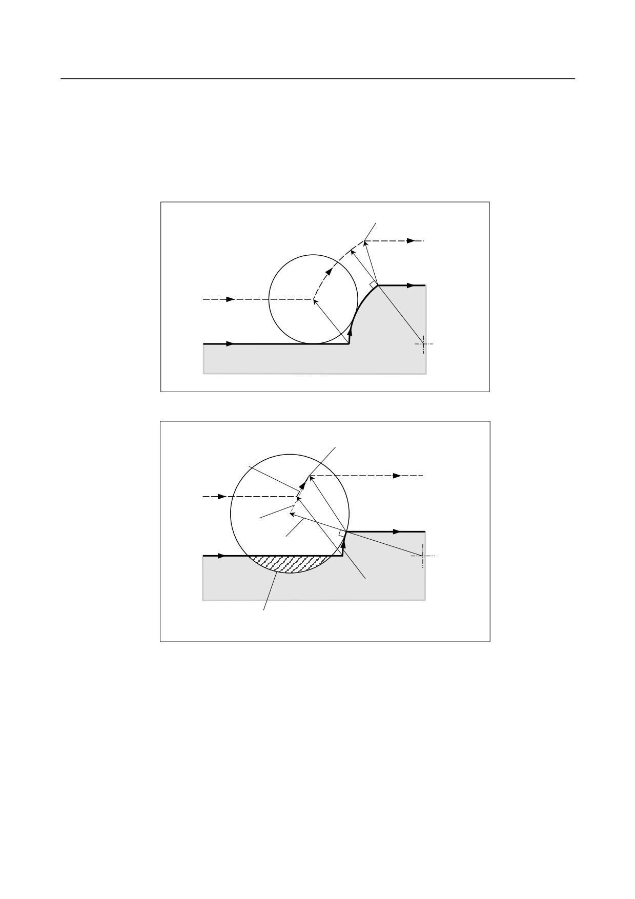
-
Machining a groove smaller than the diameter of the tool
Since the cutter compensation forces the tool center path to move in the reverse of the programmed
direction, overcutting will result. In this case an alarm is displayed and the CNC stops at the start of the
block.
An alarm is displayed and
Tool center path
the operation stops
Programmed path
Workpiece
Overcutting if the operation would not stop
Fig. 6.6.5 (a) Machining a groove smaller than the diameter of the tool
- 222 -
B-64484EN-2/02
PROGRAMMING
6.COMPENSATION FUNCTION
-
Machining a step smaller than the tool radius
For a figure in which a workpiece step is specified with an arc, the tool center path will be as shown in
Fig. 6.6.5 (b). If the step is smaller than the tool radius, the tool center path usually compensated as
shown in Fig. 6.6.5 (c) may be in the direction opposite to the programmed path. In this case, the first
vector is ignored, and the tool moves linearly to the second vector position. The single block operation is
stopped at this point. If the machining is not in the single block mode, the cycle operation is continued.
If the step is of linear, no alarm will be generated and cut correctly. However uncut part will remain.
Single block stop point
S
Tool center path
Programmed path
S
Arc center
Workpiece
Fig. 6.6.5 (b) Machining a step larger than the tool radius
Single block stop point
Linear movement
S
Tool center path
Path to be taken if
the
Programmed path
vector is not ignored
The first vector is ignored
Arc center
Arc
Workpiece
An overcutting will result if the first vector is not ignored.
However, tool moves linearly.
Fig. 6.6.5 (c) Machining a step smaller than the tool radius
-
Starting compensation and cutting along the Z-axis
It is usually used such a method that the tool is moved along the Z axis after the cutter compensation
(normally XY plane) is effected at some distance from the workpiece at the start of the machining. In the
case above, if it is desired to divide the motion along the Z axis into rapid traverse and cutting feed,
follow the procedure below.
Let us consider the program in the Fig. 6.6.5 (d), assuming the number of blocks to read in cutter
compensation mode (parameter No. 19625) to be 3.
- 223 -
6.COMPENSATION FUNCTION
PROGRAMMING
B-64484EN-2/02
N1 G91 G00 G41 X500.0 Y500.0 D1 ;
N3 G01 Z-300.0 F100 ;
N6 Y1000.0 F200 ;
After compensation
Workpiece
N6
N3:Move command in Z axis (one block)
N1
Fig. 6.6.5 (d)
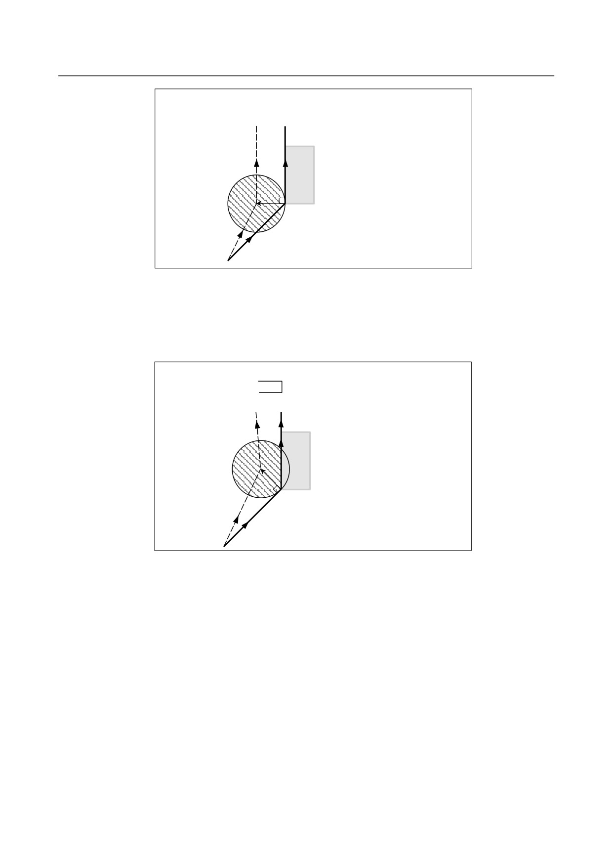
In the program example in the Fig. 6.6.5 (d), when executing block N1, blocks N3 and N6 are also
entered into the buffer storage, and by the relationship among them the correct compensation is
performed as in the Fig. 6.6.5 (d).
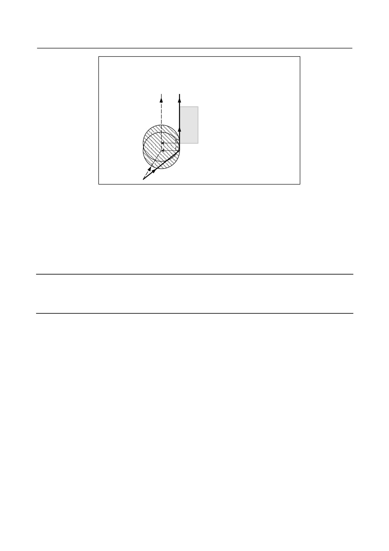
Then, suppose that the block N3 (move command in Z axis) is divided into N3 and N5 in the Fig. 6.6.5
(e).
N1 G91 G00 G41 X500.0 Y500.0 D1 ;
N3 G01 Z-250.0 ;
N5 G01 Z-50.0 F100 ;
N6 Y1000.0 F200 ;
After compensation
Workpiece
N6
N3, N5:Move command for the Z axis (two blocks)
N1
Fig. 6.6.5 (e)
At this time, because the number of blocks to read is 3, blocks up to N5 can be read at the start of N1
compensation, but block N6 cannot be read. As a result, compensation is performed only on the basis of
the information in block N1, and a vertical vector is created at the end of the compensation start block.
Usually, therefore, overcutting will result as shown in the Fig. 6.6.5 (e).
In such a case, it is possible to prevent overcutting by specifying a command with the exactly the same
direction as the advance direction immediately before movement along the Z axis beforehand, after the
tool is moved along the Z axis using the above rule.
- 224 -
B-64484EN-2/02
PROGRAMMING
6.COMPENSATION FUNCTION
N1 G91 G00 G41 X500.0 Y400.0 D1 ;
N2 Y100.0 ;
N3 Z-250.0 ;
N5 G01 Z-50.0 F100 ;
N6 Y1000.0 F200 ;
After compensation
N6
W orkpiece
N3, N5 : Move command for the Z axis (2 blocks)
N2
N1
Fig. 6.6.5 (f)
As the block with sequence N2 has the move command in the same direction as that of the block with
sequence N6, the correct compensation is performed.
Alternatively, it is possible to prevent overcutting in the same way by specifying an IJ type vector with
the same direction as the advance direction in the start-up block, as in N1 G91 G00 G41 X500. Y500. I0
J1 D1;, after the tool has moved along the Z axis.
6.6.6
Interference Check
Tool overcutting is called interference. The interference check function checks for tool overcutting in
advance. However, all interference cannot be checked by this function. The interference check is
performed even if overcutting does not occur.
Explanation
-
Condition under which an interference check is possible
To perform an interference check, it is necessary to read at least three blocks with tool movement. If,
therefore, three or more blocks with tool movement cannot be read in offset mode because blocks without
tool movement, such as independent auxiliary function and dwell, are specified in succession, excessive
or insufficient cutting may occur because an interference check fails. Assuming the number of blocks to
read in offset mode, which is determined by parameter No. 19625, to be N and the number of commands
in those N blocks without tool movement that have been read to be M, the condition under which an
interference check is possible is
(N - 3) ≥ M.
For example, if the maximum number of blocks to read in offset mode is 8, an interference check is
possible even if up to five blocks without tool movement are specified. In this case, three adjacent blocks
can be checked for interference, but any subsequent interference that may occur cannot be detected.
-
Interference check method
Two interference check methods are available, direction check and circular angle check. Bit 1 (CNC) of
parameter No. 5008 and bit 3 (CNV) of parameter No. 5008 are used to specify whether to enable these
methods.
- 225 -
6.COMPENSATION FUNCTION
PROGRAMMING
B-64484EN-2/02
Parameter CNV
Parameter CNC
Operation
An interference check is enabled, and a direction check and a circular
0
0
angle check can be performed.
An interference check is enabled, and only a circular angle check is
0
1
performed.
1
-
An interference check is disabled.
NOTE
There are no settings for performing a direction check only.
-
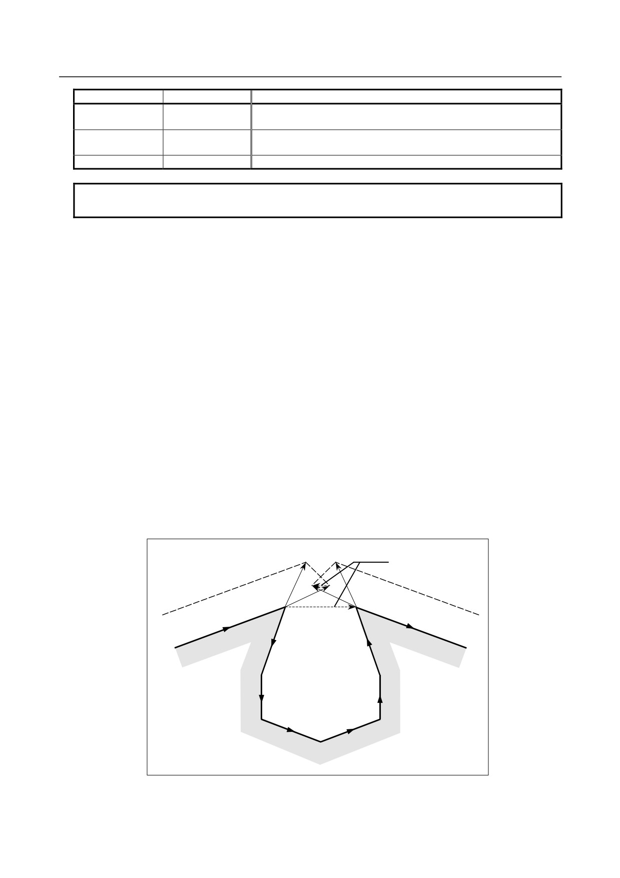
Interference reference <1> (direction check)
Assuming the number of blocks to read during cutter compensation to be N, a check is first performed on
the compensation vector group calculated in
(block
1 - block
2) to be output this time and the
compensation vector group calculated in (block N-1 - block N); if they intersect, they are judged to
interfere. If no interference is found, a check is performed sequentially in the direction toward the
compensation vector group to be output this time, as follows:
(Block 1 - block 2) and (block N-2 - block N-1)
(Block 1 - block 2) and (block N-3 - block N-2)
:
:
(Block 1 - block 2) and (block 2 - block 3)
Even if multiple number of compensation vector groups are generated, a check is performed on all pairs.
The judgment method is as follows: For a check on the compensation vector group in (block 1 - block 2)
and those in (block N-1 - block N), the direction vector from the specified (end point of block 1) to the
(end point of block N-1) is compared with the direction vector from the (point resulting from adding the
compensation vector to be checked to the end of block 1) to the (point resulting from adding the
compensation vector to be checked to the end of block N-1), and if the direction is 90o or greater or 270o
or less, they are judged to intersect and interfere. This is called a direction check.
Example of interference standard <1>
(If the block 1 end-point vector intersects with the block 7 end-point vector)
The direction differs by
180°.
Tool center path
Programmed path
Block 2
Block 7
Block 1
Block 8
Block 3
Block 6
Block 4
Block 5
- 226 -
B-64484EN-2/02
PROGRAMMING
6.COMPENSATION FUNCTION
Example of interference standard <1>
(If the block 1 end-point vector intersects with the block 2 end-point vector)
Programmed path
Tool center path
Block 1
The directions of
these two paths are
different (180°).
Block 2
-
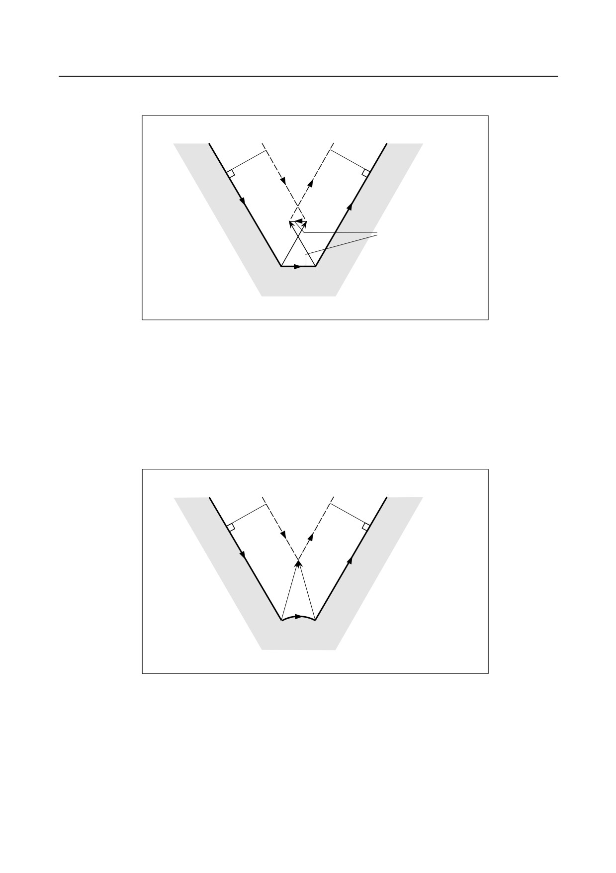
Interference reference <2> (circular angle check)
In a check on three adjacent blocks, that is, a check on the compensation vector group calculated on
(block 1 - block 2) and the compensation vector group calculated on (block 2 - block 3), if block 2 is
circular, a check is performed on the circular angle between the start and end points of the programmed
path and the circular angle of the start and end point of the post-compensation path, in addition to
direction check <1>. If the difference is 180o or greater, the blocks are judged to interfere. This is called a
circular angle check.
Example of <2> (if block 2 is circular and the start point of the post-compensation arc coincide with the
end point)
Tool center path
Programmed path
Block 3
Block 1
Programmed path
Block 2
- 227 -
6.COMPENSATION FUNCTION
PROGRAMMING
B-64484EN-2/02
-
When interference is assumed although actual interference does not occur
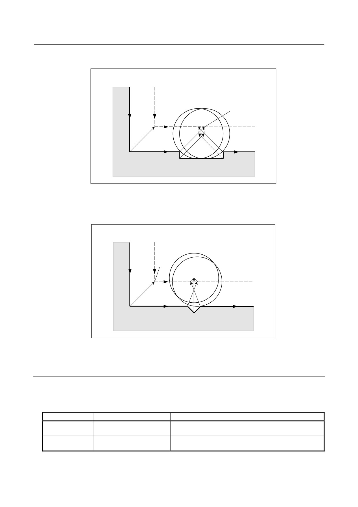
<1> Depression which is smaller than the tool radius ⋅ tool nose radius compensation value
Programmed
path
Tool center path
Stopped
A
C
B
There is no actual interference, but since the direction programmed in block B is opposite to that of
the path after the cutter compensation, the tool stops and an alarm is displayed.
<2> Groove which is smaller than the tool radius ⋅ tool nose radius compensation value
Programmed
path
Tool center path
Stopped
A
B
C
Like <1>, an alarm is displayed because of the interference as the direction is reverse in block B.
6.6.6.1 Operation to be performed if an interference is judged to
occur
The operation to be performed if an interference check judges that an interference (due to overcutting)
occurs can be either of the following two, depending on the setting of bit 5 (CAV) of parameter No.
19607.
Parameter CAV
Function
Operation
Interference check alarm
An alarm stop occurs before the execution of the block in
0
function
which overcutting (interference) occurs.
Interference check avoidance
The tool path is changed so that overcutting (interference)
1
function
does not occur, and processing continues.
- 228 -
B-64484EN-2/02
PROGRAMMING
6.COMPENSATION FUNCTION
6.6.6.2 Interference check alarm function
-
Interference other than those between adjacent three blocks
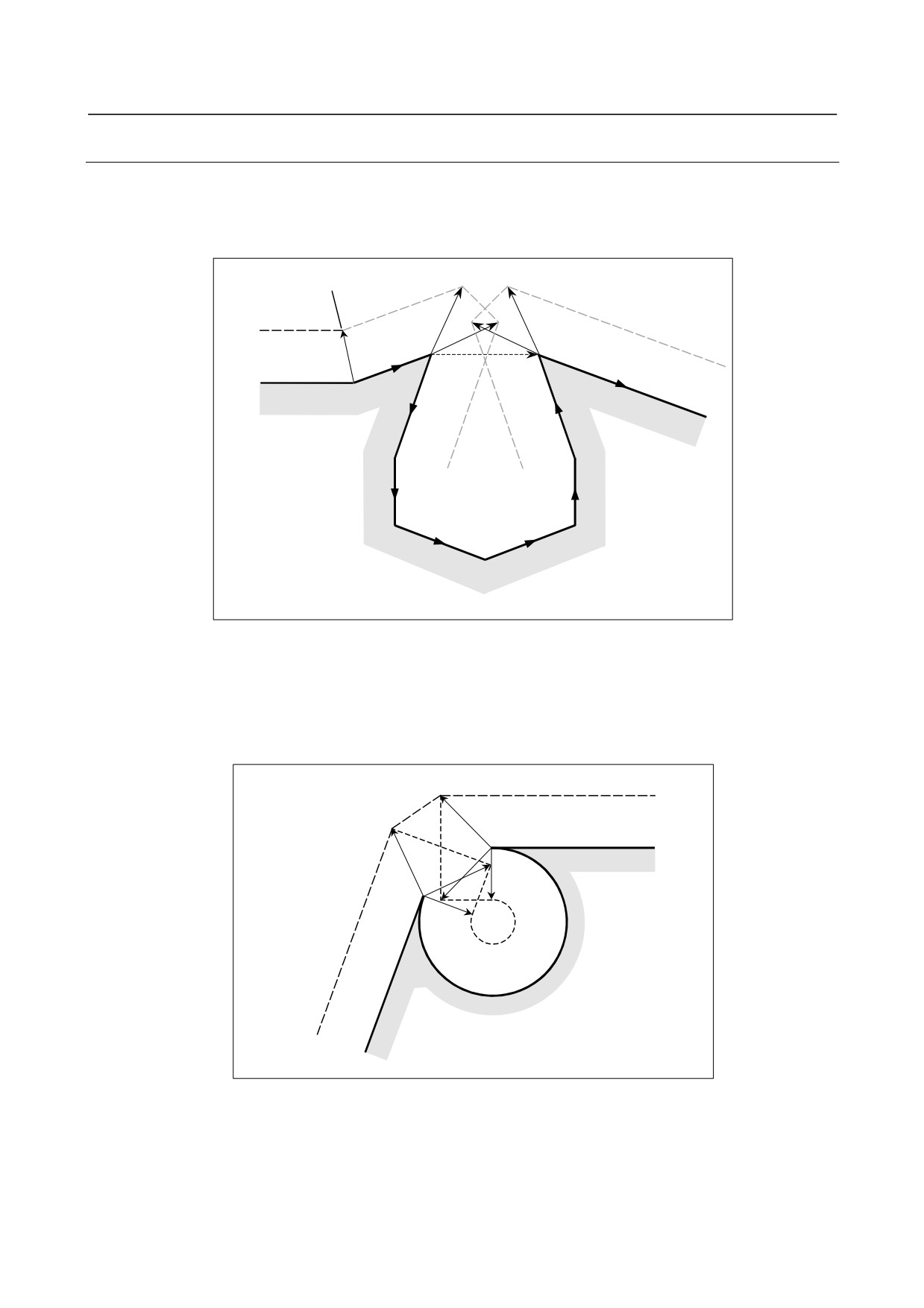
If the end-point vector of block 1 and the end-point vector of block 7 are judged to interfere as shown in
the Fig. 6.6.6.2 (a), an alarm will occur before the execution of block 1 so that the tool stops. In this case,
the vectors will not be erased.
Stopped
Tool center path
Block 1
Block 8
Programmed path
Block 2
Block 7
Block 3
Block 6
Block 4
Block 5
Fig. 6.6.6.2 (a)
-
Interference between adjacent three blocks
If an interference is judged to occur between adjacent three blocks, the interfering vector, as well as any
vectors existing inside of it, is erased, and a path is created to connect the remaining vectors. In the
Example shown in the Fig. 6.6.6.2 (b), V2 and V5 interfere, so that V2 and V5 are erased, so are V3 and V4,
which are inside of them, and V1 is connected to V6. The operation during this time is linear interpolation.
V6
V1
V2
V5
V4
V3
Tool center path
Programmed path
Fig. 6.6.6.2 (b)
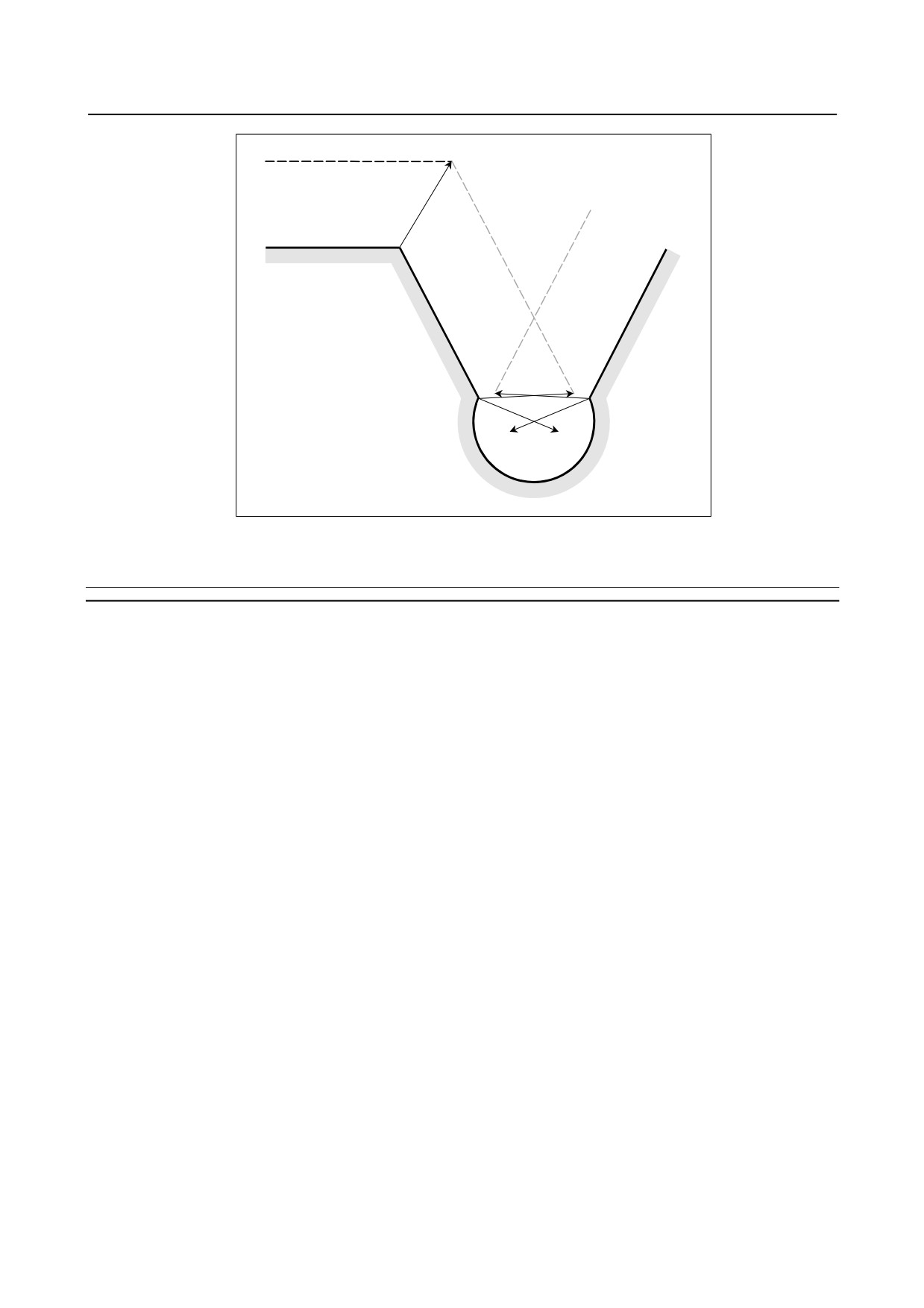
If, after vector erasure, the last single vector still interferes, or if there is only one vector at the beginning
and it interferes, an alarm will occur immediately after the start of the previous block (end point for a
single block) and the tool stops. In the Example shown in the Fig. 6.6.6.2 (c), V2 and V3 interfere, but,
even after erasure, an alarm will occur because the final vectors V1 and V4 interfere.
- 229 -
6.COMPENSATION FUNCTION
PROGRAMMING
B-64484EN-2/02
Stopped
Tool center path
Programmed path
V4
V1
V3
V2
Fig. 6.6.6.2 (c)
6.6.6.3 Interference check avoidance function
Overview
If a command is specified which satisfies the condition under which the interference check alarm function
generates an interference alarm, this function suppresses the generation of the interference alarm, but
causes a new compensation vector to be calculated as a path for avoiding interference, thereby continuing
machining. For the path for avoiding interference, insufficient cutting occurs in comparison with the
programmed path. In addition, depending on the specified figure, no path for avoiding interference can be
determined or the path for avoiding interference may be judged dangerous. In such a case, an alarm stop
will occur. For this reason, it is not always possible to avoid interference for all commands.
-
Interference avoidance method
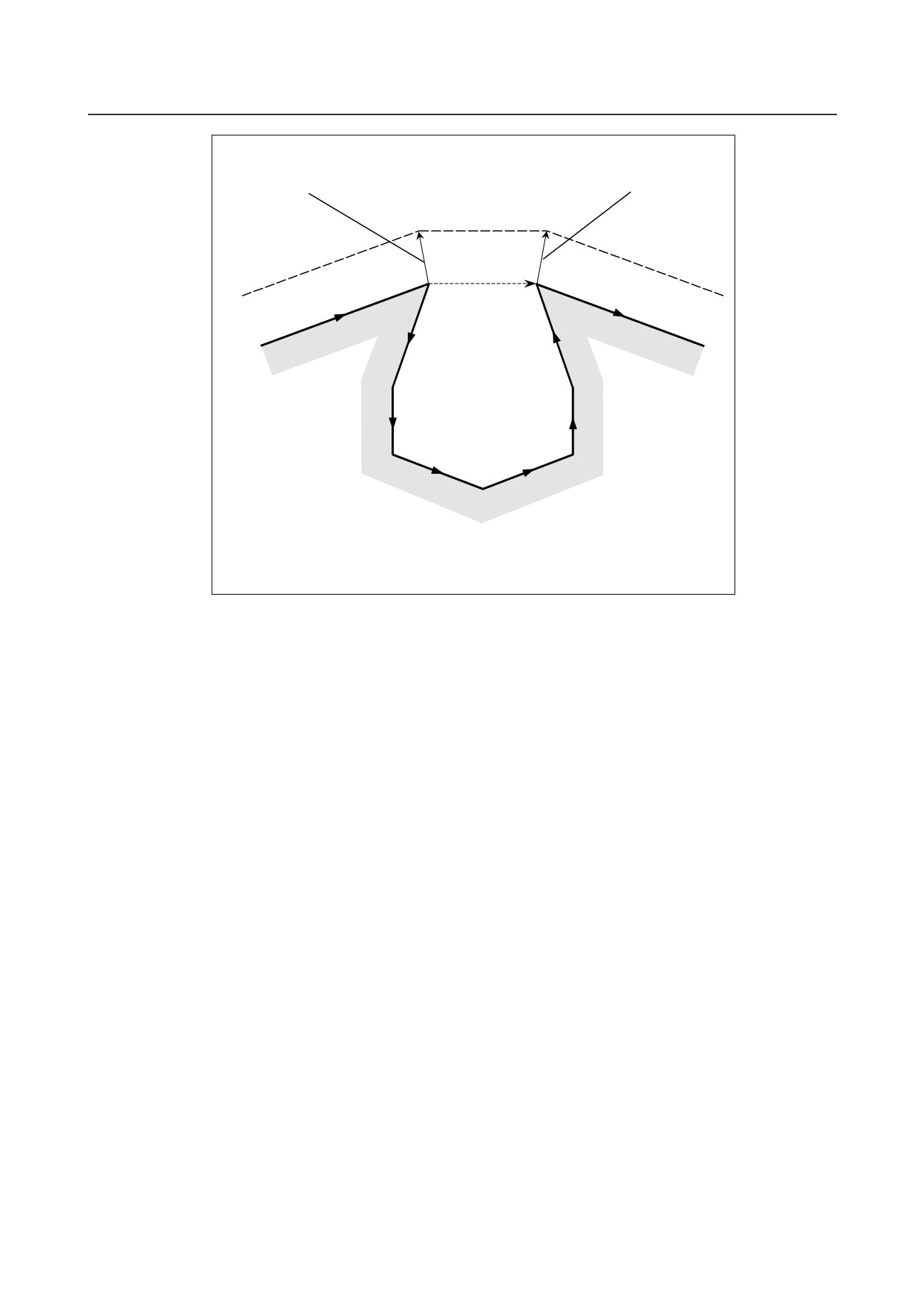
Let us consider a case in which an interference occurs between the compensation vector between (block 1
- block 2) and the compensation vector between (block N-1 - block N). The direction vector from the end
point of block 1 to the end point of block N-1 is called a gap vector. At this time, a post-compensation
intersection vector between (block 1 - gap vector) and a post-compensation intersection vector between
(gap vector - block N) is determined, and a path connecting them is created.
- 230 -
B-64484EN-2/02
PROGRAMMING
6.COMPENSATION FUNCTION
Post-compensation intersection vector
Post-compensation intersection vector
between gap vector and block 8
between block 1 and gap vector
Movement o f block 7
Post-compensation
path
Gap vector
Block 1
Block 8
Block 2
Block 7
Programmed path
Block 3
Block 6
Block 4
Block 5
In this case, the post-compensation end points of blocks 2 to 6 coincide with the end
point of block 1. Thus, after compensation, blocks 2 to 6 will be blocks without tool
movement.
Fig. 6.6.6.3 (a)
If the post-compensation intersection vector of
(block
1 - gap vector) and the post-compensation
intersection vector of (gap vector - block N) further intersect, vector erasure is first performed in the same
way as in "Interference between adjacent three blocks". If the last vectors that remains still intersects, the
post-compensation intersection vector of (block 1 - block N) is re-calculated.
- 231 -