FANUC Series 30i-MODEL B, 31i-MODEL B, 32i-MODEL B. For Machining Center System. OPERATOR'S MANUAL - page 6
5. FUNCTIONS TO SIMPLIFY
PROGRAMMING
PROGRAMMING
B-64484EN-2/02
-
Target figure
Patterns
As in the case of G71.7, there are four target figure patterns. Be careful about signs of Δu, Δw, Δi, and Δk
when programming this cycle.
-
Start block
In the start block in the program for a target figure (block with sequence number ns in which the path
between A and A’ is specified), G00 or G01 must be specified. If it is not specified, alarm PS0065 is
issued.
When G00 is specified, positioning is performed along A-A’. When G01 is specified, linear interpolation
is performed with cutting feed along A-A’.
-
Check functions
The following check can be made.
Check
Related parameter
Checks that a block with the sequence number specified at address Q is
Enabled when bit 2 (QSR) of
contained in the program before cycle operation.
parameter No. 5102 is set to 1.
-
Tool nose radius compensation
Like G71.7, this cycle operation is performed according to the figure determined by the tool nose radius
compensation path when the offset vector is 0 at start point A and start-up is performed in a block
between path A-A'.
- 142 -
5.FUNCTIONS TO SIMPLIFY
B-64484EN-2/02
PROGRAMMING
PROGRAMMING
5.8.4
Finishing Cycle (G70.7)
After rough cutting by G71.7, G72.7 or G73.7, the following command permits finishing.
Format
G70.7 P(ns) Q(nf) ;
ns : Sequence number of the first block for the program of finishing shape.
nf : Sequence number of the last block for the program of finishing shape.
Explanation
-
Operations
The blocks with sequence numbers ns to nf in the program for a target figure are executed for finishing.
The F, S, T, M, and second auxiliary functions specified in the G71.7, G72.7, or G73.7 block are ignored
and the F, S, T, M, and second auxiliary functions specified in the blocks with sequence numbers ns to nf
are effective.
When cycle operation terminates, the tool is returned to the start point in rapid traverse and the next
G70.7 cycle block is read.
-
Target figure
Check function
Following check can be made.
Check
Related parameter
Checks that a block with the sequence number specified at address Q is
Enabled when bit 2 (QSR) of
contained in the program before cycle operation.
parameter No. 5102 is set to 1.
-
Storing P and Q blocks
When rough cutting is executed by G71.7, G72.7, or G73.7, up to three memory addresses of P and Q
blocks are stored. By this, the blocks indicated by P and Q are immediately found at execution of G70.7
without searching memory from the beginning for them. After some G71.7, G72.7, and G73.7 rough
cutting cycles are executed, finishing cycles can be performed by G70.7 at a time. At this time, for the
fourth and subsequent rough cutting cycles, the cycle time is longer because memory is searched for P
and Q blocks.
Example
G71.7 P100 Q200 - - - ;
N100 - - - ;
- - - ;
- - - ;
N200 - - - ;
G71.7 P300 Q400 - - - ;
N300 - - - ;
- - - ;
- - - ;
N400 - - - ;
- - - ;
- - - ;
G70.7 P100 Q200 ; (Executed without a search for the first to third cycles)
G70.7 P300 Q400 ; (Executed after a search for the fourth and subsequent
cycles)
- 143 -
5. FUNCTIONS TO SIMPLIFY
PROGRAMMING
PROGRAMMING
B-64484EN-2/02
NOTE
The memory addresses of P and Q blocks stored during rough cutting cycles by
G71.7, G72.7, and G73.7 are erased after execution of G70.7.
All stored memory addresses of P and Q blocks are also erased by a reset.
-
Return to the cycle start point
In a finishing cycle, after the tool cuts the workpiece to the end point of the target figure, it returns to the
cycle start point in rapid traverse.
NOTE
The tool returns to the cycle start point always in the nonlinear positioning mode
regardless of the setting of bit 1 (LRP) of parameter No. 1401.
Before executing a finishing cycle for a target figure with a pocket cut by G71.7
or G72.7, check that the tool does not interfere with the workpiece when
returning from the end point of the target figure to the cycle start point.
-
Tool nose radius compensation
When using tool nose radius compensation, specify a tool nose radius compensation command (G41 or
G42) before a multiple repetitive canned cycle command (G70.7) and specify the cancel command (G40)
after the multiple repetitive canned cycle command (G70.7).
Program example
G42;
Specify this command before a multiple repetitive canned cycle command.
G70.7P10Q20;
G40;
Specify this command after a multiple repetitive canned cycle command.
Like G71.7, this cycle operation is performed according to the figure determined by the tool nose radius
compensation path when the offset vector is 0 at start point A and start-up is performed in a block
between path A-A'.
- 144 -
5.FUNCTIONS TO SIMPLIFY
B-64484EN-2/02
PROGRAMMING
PROGRAMMING
Example
Stock removal in facing (G72.7)
X axis
2
Start point
7
Z axis
60
10
10
10
20
20
2
190
(Diameter designation for X axis, metric input)
N010
G90G92 X220.0 Z190.0 ;
N011
G00 X176.0 Z132.0 ;
N012
G72.7 W7.0 R1.0 ;
N013
G72.7 P014 Q019 U4.0 W2.0 F0.3 S550 ;
N014
G00 Z56.0 S700 ;
N015
G01 X120.0 Z70.0 F0.15 ;
N016
Z80.0 ;
N017
X80.0 Z90.0 ;
N018
Z110.0 ;
N019
X36.0 Z132.0 ;
N020
G70.7 P014 Q019 ;
Escaping amount:
1.0
Finishing allowance (4.0 in diameter in the X direction, 2.0 in the Z direction)
- 145 -
5. FUNCTIONS TO SIMPLIFY
PROGRAMMING
PROGRAMMING
B-64484EN-2/02
Pattern repeating (G73.7)
16
B
X axis
Z axis
0
2
14
20
40
10
40
10
20
40
220
(Diameter designation, metric input)
N010
G90G92 X260.0 Z220.0 ;
N011
G00 X220.0 Z160.0 ;
N012
G73.7 U14.0 W14.0 R3 ;
N013
G73.7 P014 Q019 U4.0 W2.0 F0.3 S0180 ;
N014
G00 X80.0 Z120.0 ;
N015
G01 Z100.0 F0.15 S0600 ;
N016
X120.0 Z90.0;
N017
Z70.0 S0400 ;
N018
G02 X160.0 Z50.0 R20.0 ;
N019
G01 X180.0 Z40.0 S0280 ;
N020
G70.7 P014 Q019 ;
- 146 -
5.FUNCTIONS TO SIMPLIFY
B-64484EN-2/02
PROGRAMMING
PROGRAMMING
5.8.5
End Face Peck Drilling Cycle (G74.7)
This cycle enables chip breaking in outer diameter cutting. If the second axis on the plane (X-axis
(U-axis) for the ZX plane) and address P are omitted, operation is performed only along the first axis on
the plane (Z-axis for the ZX plane), that is, a peck drilling cycle is performed.
Format
G74.7R (e) ;
G74.7X_ Z_ P(Δi) Q(Δk) R(Δd) F (f ) ;
e
: Return amount
This designation is modal and is not changed until the other value is designated.
Also this value can be specified by the parameter No. 5139, and the parameter is
changed by the program command.
X_,Z_ : Coordinate of the second axis on the plane (X-axis for the ZX plane) at point B and
Coordinate of the first axis on the plane (Z-axis for the ZX plane) at point C
For an absolute command, coordinates (X,Z)
For an incremental command, travel distance (Δx, Δz)
Δi
: Travel distance in the direction of the second axis on the plane (X-axis for the ZX
plane)
Δk
: Depth of cut in the direction of the first axis on the plane (Z-axis for the ZX plane)
Δd
: Relief amount of the tool at the cutting bottom
f
: Feedrate
Diameter/radius
Decimal
Unit
Sign
programming
point input
Depends on the increment system
e
Radius programming
Not required
Allowed
for the reference axis.
Depends on the increment system
Δi
Radius programming
Not required
Not allowed
for the reference axis.
Depends on the increment system
Δk
Radius programming
Not required
Not allowed
for the reference axis.
Depends on the increment system
Δd
Radius programming
Note
Allowed
for the reference axis.
NOTE
Normally, specify a positive value for Δd. When X and Δi are omitted, specify a
value with the sign indicating the direction in which the tool is to escape.
- 147 -
5. FUNCTIONS TO SIMPLIFY
PROGRAMMING
PROGRAMMING
B-64484EN-2/02
Δk'
Δk
Δk
Δk
Δk
[0<Δk’≤Δk]
Δd
A
Δi
C
(R)
(R)
(F)
(F)
(F)
(F)
Δx/2
(R)
(R)
(R)
(R)
Δi
[0<Δi’≤Δi]
Δi’
X
Z
Δz
B
+X
(R) ... Rapid traverse
(F) ... Cutting feed
e
+Z
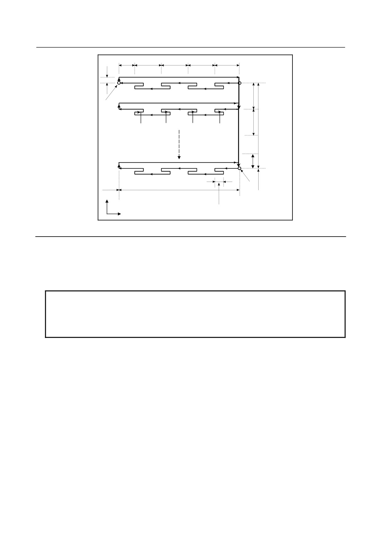
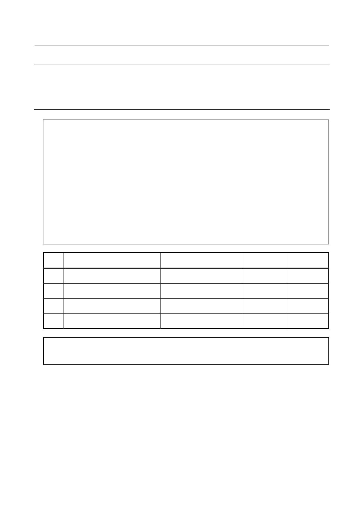
Fig. 5.8.5 (a) Cutting path in end face peek drilling cycle
Explanation
-
Operations
A cycle operation of cutting by Δk and return by e is repeated.
When cutting reaches point C, the tool escapes by Δd. Then, the tool returns in rapid traverse, moves to
the direction of point B by Δi, and performs cutting again.
NOTE
1 For e and Δd, the same address must be specified. They are distinguished from
each other according to whether an axis, such as X, Y, and Z is specified. That
is, if an axis is specified, the address is regarded as being that for Δd.
2 A cycle operation is performed with a G74.7 command with an axis specified.
-
Tool nose radius compensation
Tool nose radius compensation cannot be applied.
- 148 -
5.FUNCTIONS TO SIMPLIFY
B-64484EN-2/02
PROGRAMMING
PROGRAMMING
5.8.6
Outer Diameter / Internal Diameter Drilling Cycle (G75.7)
This cycle is equivalent to G74.7 except that the second axis on the plane (X-axis for the ZX plane)
changes places with the first axis on the plane (Z-axis for the ZX plane). This cycle enables chip breaking
in end facing. It also enables grooving during outer diameter cutting and cutting off (when the Z-axis and
Q are omitted for the first axis on the plane).
Format
G75.7R (e) ;
G75.7X_ Z_ P(Δi) Q(Δk) R(Δd) F (f ) ;
e
: Return amount
This designation is modal and is not changed until the other value is designated.
Also this value can be specified by the parameter No. 5139, and the parameter is
changed by the program command.
X_,Z_ : Coordinate of the second axis on the plane (X-axis for the ZX plane) at point B and
Coordinate of the first axis on the plane (Z-axis for the ZX plane) at point C
For an absolute command, coordinates (X,Z)
For an incremental command, travel distance (Δx, Δz)
Δi
: Depth of cut in the direction of the second axis on the plane (X-axis for the ZX plane)
Δk
: Travel distance in the direction of the first axis on the plane (Z-axis for the ZX plane)
Δd
: Relief amount of the tool at the cutting bottom
f
: Feedrate
Diameter/radius
Decimal
Unit
Sign
programming
point input
Depends on the increment system
e
Radius programming
Not required
Allowed
for the reference axis.
Depends on the increment system
Δi
Radius programming
Not required
Not allowed
for the reference axis.
Depends on the increment system
Δk
Radius programming
Not required
Not allowed
for the reference axis.
Depends on the increment system
Δd
Radius programming
Note
Allowed
for the reference axis.
NOTE
Normally, specify a positive value for Δd. When Z and Δk are omitted, specify a
value with the sign indicating the direction in which the tool is to escape.
- 149 -
5. FUNCTIONS TO SIMPLIFY
PROGRAMMING
PROGRAMMING
B-64484EN-2/02
C
(R)
A
(R)
(F)
Δi
(R)
e
(F)
Δi
(R)
Δx/2
(F)
Δi
(R)
(F)
Δi
(R)
(F)
Δi’
B
Δd
Δk
X
Z
Δz
+X
(R)…Rapid traverse
(F)…Cutting feed
+Z
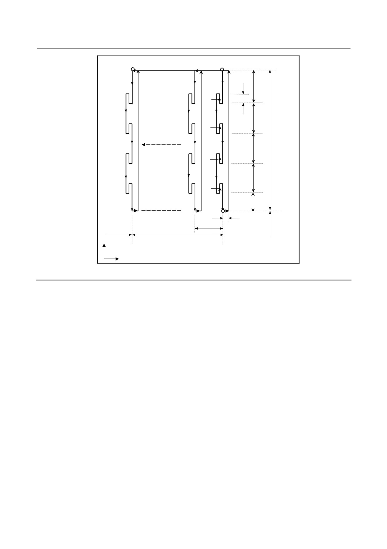
Fig. 5.8.6 (a) Outer diameter/internal diameter drilling cycle
Explanation
-
Operations
A cycle operation of cutting by Δi and return by e is repeated.
When cutting reaches point B, the tool escapes by Δd. Then, the tool returns in rapid traverse, moves to
the direction of point C by Δk, and performs cutting again.
Both G74.7 and G75.7 are used for grooving and drilling, and permit the tool to relief automatically. Four
symmetrical patterns are considered, respectively.
-
Tool nose radius compensation
Tool nose radius compensation cannot be applied.
- 150 -

5.FUNCTIONS TO SIMPLIFY
B-64484EN-2/02
PROGRAMMING
PROGRAMMING
5.8.7
Multiple Threading Cycle (G76.7)
This threading cycle performs one edge cutting by the constant amount of cut.
Format
G76.7 P(m) (r) (a) Q(Δdmin) R(d ) ;
G76.7 X_ Z_ R(i ) P(k ) Q(Δd) F (L ) ;
m : Repetitive count in finishing (1 to 99)
This value can be specified by the parameter No. 5142, and the parameter is changed
by the program command.
r
: Chamfering amount (0 to 99)
When the thread lead is expressed by L, the value of L can be set from 0.0L to 9.9L in
0.1L increment (2-digit number). This value can be specified by the parameter No.
5130, and the parameter is changed by the program command.
a
: Angle of tool nose (thread angle)
One of six kinds of angle, 80°, 60°, 55°, 30°, 29°, and 0°, can be selected, and specified
by 2-digit number. This value can be specified by the parameter No. 5143, and the
parameter is changed by the program command.
m, r, and a are specified by address P at the same time.
(Example)When m=2, r=1.2L, a=60°, specify as shown below (L is lead of thread).
P
02
12
60
a
r
m
Δdmin : Minimum cutting depth
When the cutting depth of one cycle operation becomes smaller than this limit, the
cutting depth is clamped at this value. This value can be specified by parameter
No. 5140, and the parameter is changed by the program command.
d
: Finishing allowance
This value can be specified by parameter No. 5141, and the parameter is changed
by the program command.
X_,Z_ : Coordinates of the cutting end point (point D in the Fig. 5.8.7 (a)) in the direction of
the length
For an absolute command, coordinates (X,Z)
For an incremental command, travel distance (Δx, Δz)
i
: Taper amount
If i = 0, ordinary straight threading can be made.
k
: Height of thread
Δd
: Depth of cut in 1st cut
L
: Lead of thread
- 151 -
5. FUNCTIONS TO SIMPLIFY
PROGRAMMING
PROGRAMMING
B-64484EN-2/02
Diameter/radius
Decimal
Unit
Sign
programming
point input
Depends on the increment system
Δdmin
Radius programming
Not required
Not allowed
for the reference axis.
Depends on the increment system
d
Radius programming
Not required
Allowed
for the reference axis.
Depends on the increment system
i
Radius programming
Required
Allowed
for the reference axis.
Depends on the increment system
k
Radius programming
Not required
Not allowed
for the reference axis.
Depends on the increment system
Δd
Radius programming
Not required
Not allowed
for the reference axis.
E
(R)
A
(R)
(R)
Δx/2
B
(F)
Δd
D
i
k
X
r
C
Z
Δz
+X
+Z
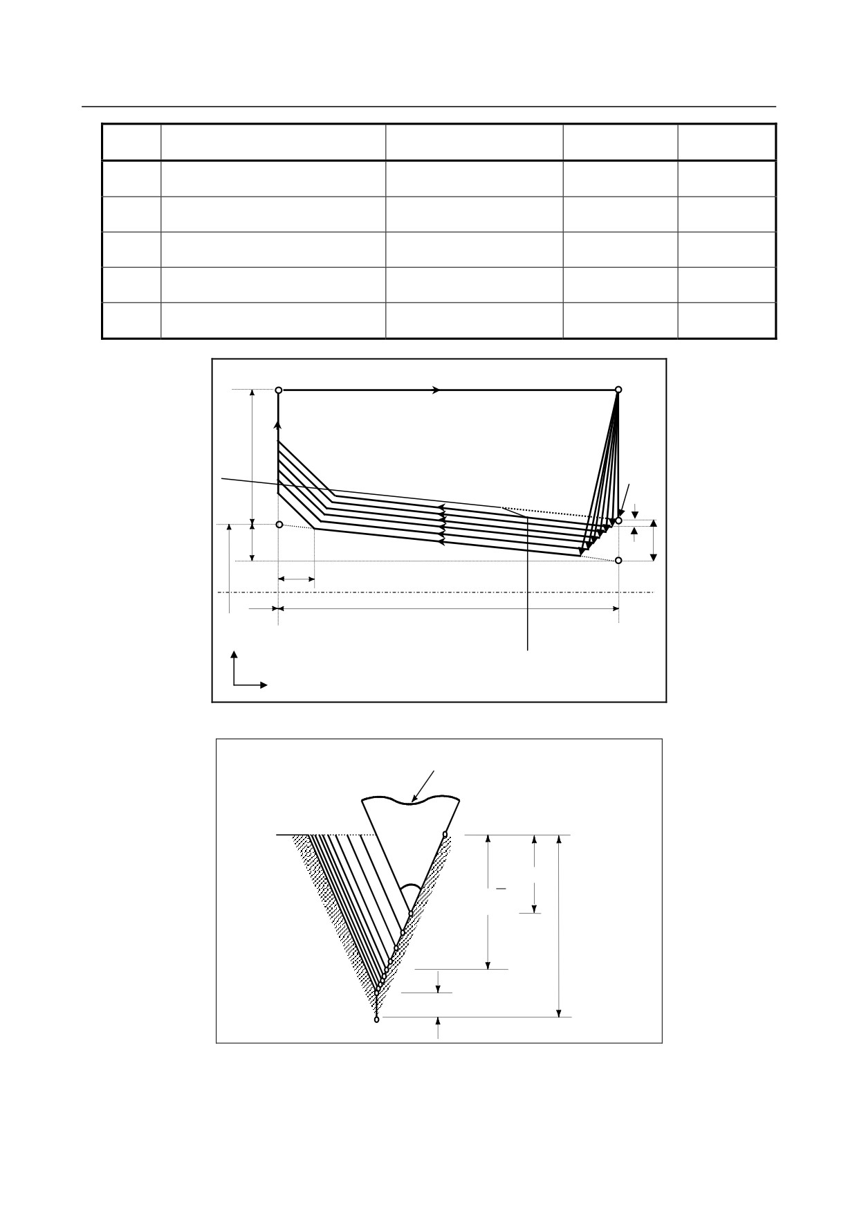
Fig. 5.8.7 (a) Cutting path in multiple threading cycle
Tool nose
B
a
Δd
Δd√n
1st
2nd
k
3rd
nth
d
Fig. 5.8.7 (b) Detail of cutting
- 152 -
5.FUNCTIONS TO SIMPLIFY
B-64484EN-2/02
PROGRAMMING
PROGRAMMING
-
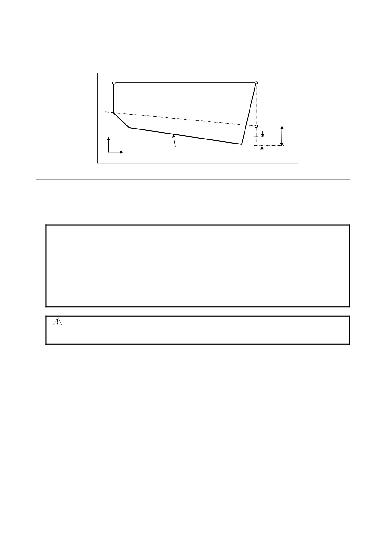
Repetitive count in finishing
The last finishing cycle (cycle in which the finishing allowance is removed by cutting) is repeated.
+X
k
+Z
Last finishing cycle
d (finishing allowance)
Fig. 5.8.7 (c)
Explanation
-
Operations
This cycle performs threading so that the length of the lead only between C and D is made as specified in
the F code. In other sections, the tool moves in rapid traverse.
NOTE
1 The meanings of the data specified by address P, Q, and R determined by the
presence of X (U) and Z (W).
2 The cycle machining is performed by G76.7 command with X and Z
specification.
3 The values specified at addresses P, Q, and R are modal and are not changed
until another value is specified.
4 Specify a value smaller than the height of thread as the finishing allowance. (d <
k)
CAUTION
Notes on threading are the same as those on G33 threading. For feed hold in a
threading cycle, however, see "Feed hold in a threading cycle" described below.
-
Relationship between the sign of the taper amount and tool path
The signs of incremental dimensions for the cycle shown in Fig. 5.8.7 (a) are as follows:
Cutting end point in the direction of the length for X and Z:
Minus (determined according to the directions of paths A-C and C-D)
Taper amount (i)
: Minus (determined according to the direction of path A-C)
Height of thread (k)
: Plus (always specified with a plus sign)
Depth of cut in the first cut (Δd)
: Plus (always specified with a plus sign)
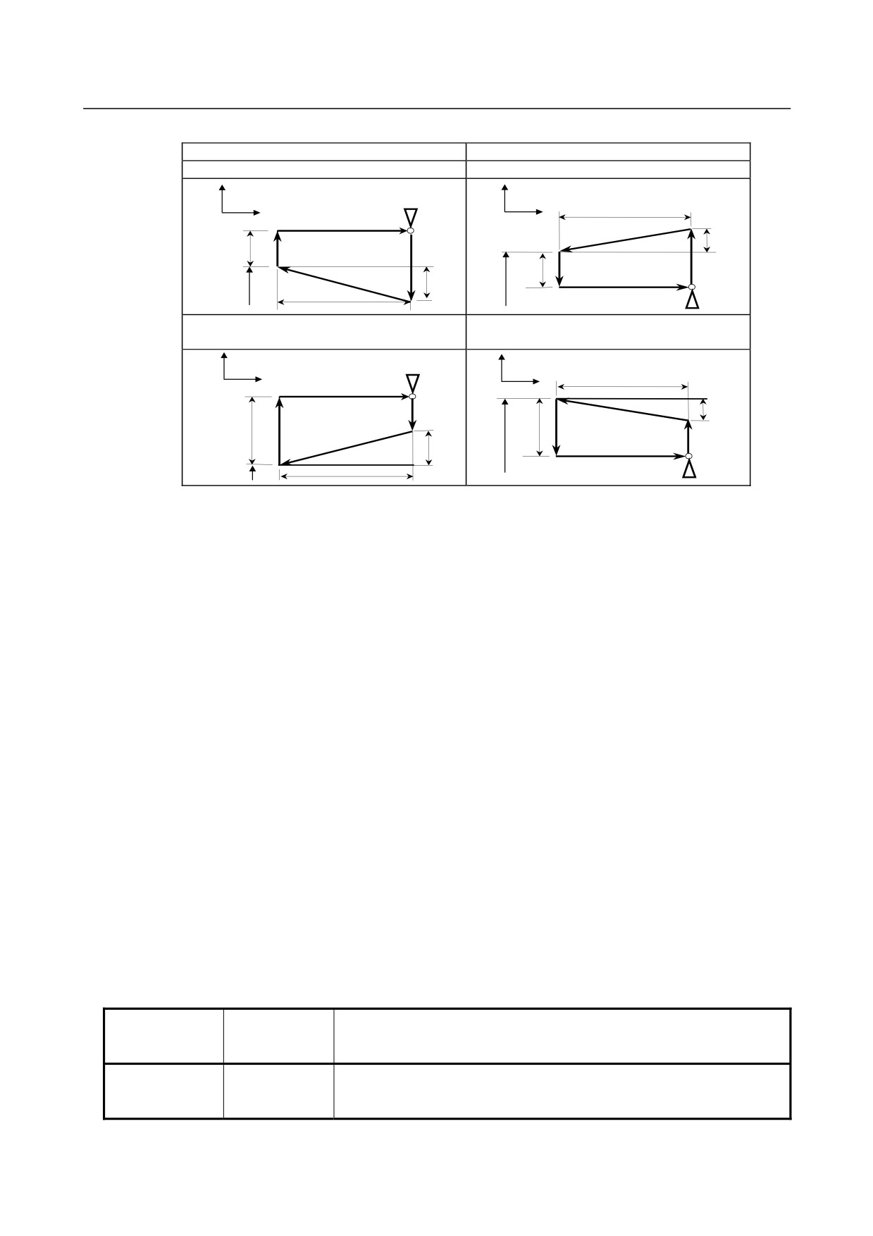
The four patterns shown in the Table 5.8.7 (a) are considered corresponding to the sign of each address. A
female thread can also be machined.
- 153 -
5. FUNCTIONS TO SIMPLIFY
PROGRAMMING
PROGRAMMING
B-64484EN-2/02
Table 5.8.7 (a)
Outer diameter machining
Internal diameter machining
1.
Δx < 0, Δz < 0, i < 0
2.
Δx > 0, Δz < 0, i > 0
X
X
Z
Z
Δz
4
(R)
2
(F)
i
Δx/2
3
(R)
1
(R)
X/2
Δx/2
3
(R)
1
(R)
i
X/2
2
(F)
Δz
4
(R)
3.
Δx < 0, Δz < 0, i > 0
4.
Δx > 0, Δz < 0, i <0
at |i |≦ |Δ x / 2|
at |i |≦ |Δ x / 2|
X
X
Z
Δz
Z
4
(R)
1
(R)
i
2
(F)
X/2
Δx/2
3
(R)
Δx/2
3
(R)
2
(F)
1
(R)
i
4
(R)
Δz
X/2
-
Acceleration/deceleration after interpolation for threading
Acceleration/deceleration after interpolation for threading is acceleration/deceleration of exponential
interpolation type. By setting bit 5 (THLx) of parameter No. 1610, the same acceleration/deceleration as
for cutting feed can be selected. (The settings of bits 1 (CTBx) and 0 (CTLx) of parameter No. 1610 are
followed.) However, as a time constant and FL feedrate, the settings of parameter No. 1626 and No. 1627
for the threading cycle are used.
-
Time constant and FL feedrate for threading
The time constant for acceleration/deceleration after interpolation for threading specified in parameter No.
1626 and the FL feedrate specified in parameter No. 1627 are used.
-
Thread chamfering
Thread chamfering can be performed in this threading cycle. A signal from the machine tool initiates
thread chamfering.
The maximum amount of thread chamfering (r) that can be specified in the command is 99 (9.9L). The
amount can be specified in a range from 0.1L to 12.7L in 0.1L increments in parameter No. 5130.
A thread chamfering angle between 1 to 89 degrees can be specified in parameter No. 5131. When a
value of 0 is specified in the parameter, an angle of 45 degrees is assumed.
For thread chamfering, the same type of acceleration/deceleration after interpolation, time constant for
acceleration/deceleration after interpolation, and FL feedrate as for threading are used.
-
Retraction after chamfering
The Table 5.8.7 (b) lists the feedrate, type of acceleration/deceleration after interpolation, and time
constant of retraction after chamfering.
Table 5.8.7 (b)
Bit 0 (CFR) of
Parameter No.
parameter No.
Description
1466
1611
Uses the type of acceleration/deceleration after interpolation for threading,
0
Other than 0
time constant for threading (parameter No. 1626), FL feedrate (parameter
No. 1627), and retraction feedrate specified in parameter No. 1466.
- 154 -
5.FUNCTIONS TO SIMPLIFY
B-64484EN-2/02
PROGRAMMING
PROGRAMMING
Bit 0 (CFR) of
Parameter No.
parameter No.
Description
1466
1611
Uses the type of acceleration/deceleration after interpolation for threading,
0
0
time constant for threading (parameter No. 1626), FL feedrate (parameter
No. 1627), and rapid traverse rate specified in parameter No. 1420.
Before retraction a check is made to see that the specified feedrate has
become 0 (delay in acceleration/deceleration is 0), and the type of
1
acceleration/deceleration after interpolation for rapid traverse is used
together with the rapid traverse time constant and the rapid traverse rate
(parameter No. 1420).
By setting bit 4 (ROC) of parameter No. 1403 to 1, rapid traverse override can be disabled for the feedrate
of retraction after chamfering.
NOTE
During retraction, the machine does not stop with an override of 0% for the
cutting feedrate regardless of the setting of bit 4 (RF0) of parameter No. 1401.
-
Shifting the start angle
The threading start angle cannot be shifted.
-
Feed hold in a threading cycle
When the threading cycle retract function is not used, the machine stops at the end point of retraction
after chamfering (point E on the cutting path for a multiple threading cycle) by feed hold applied during
threading.
-
Feed hold when the threading cycle retract function is used
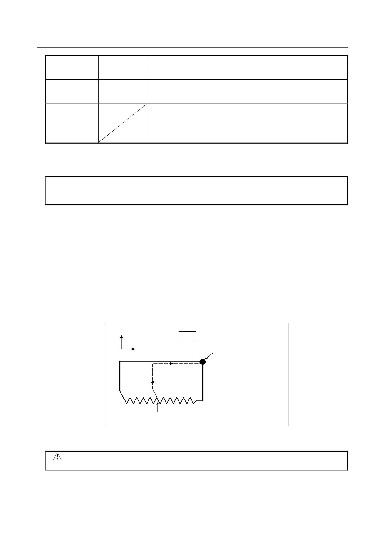
When the "threading cycle retract" optional function is used, feed hold may be applied during threading
in a multiple threading cycle (G76.7). In this case, the tool quickly retracts in the same way as for the last
chamfering in a threading cycle and returns to the start point in the current cycle.
When cycle start is triggered, the multiple threading cycle resumes.
X-axis
Ordinary cycle
Motion at feed hold
Z-axis
Start point
in the current cycle
Rapid traverse
Cutting feed
Feed hold is applied at this point
The angle of chamfering during retraction is the same as that of chamfering at the end point.
CAUTION
Another feed hold cannot be performed during retraction.
-
Inch threading
Inch threading specified with address E is not allowed.
- 155 -
5. FUNCTIONS TO SIMPLIFY
PROGRAMMING
PROGRAMMING
B-64484EN-2/02
-
Tool nose radius compensation
Tool nose radius compensation cannot be applied.
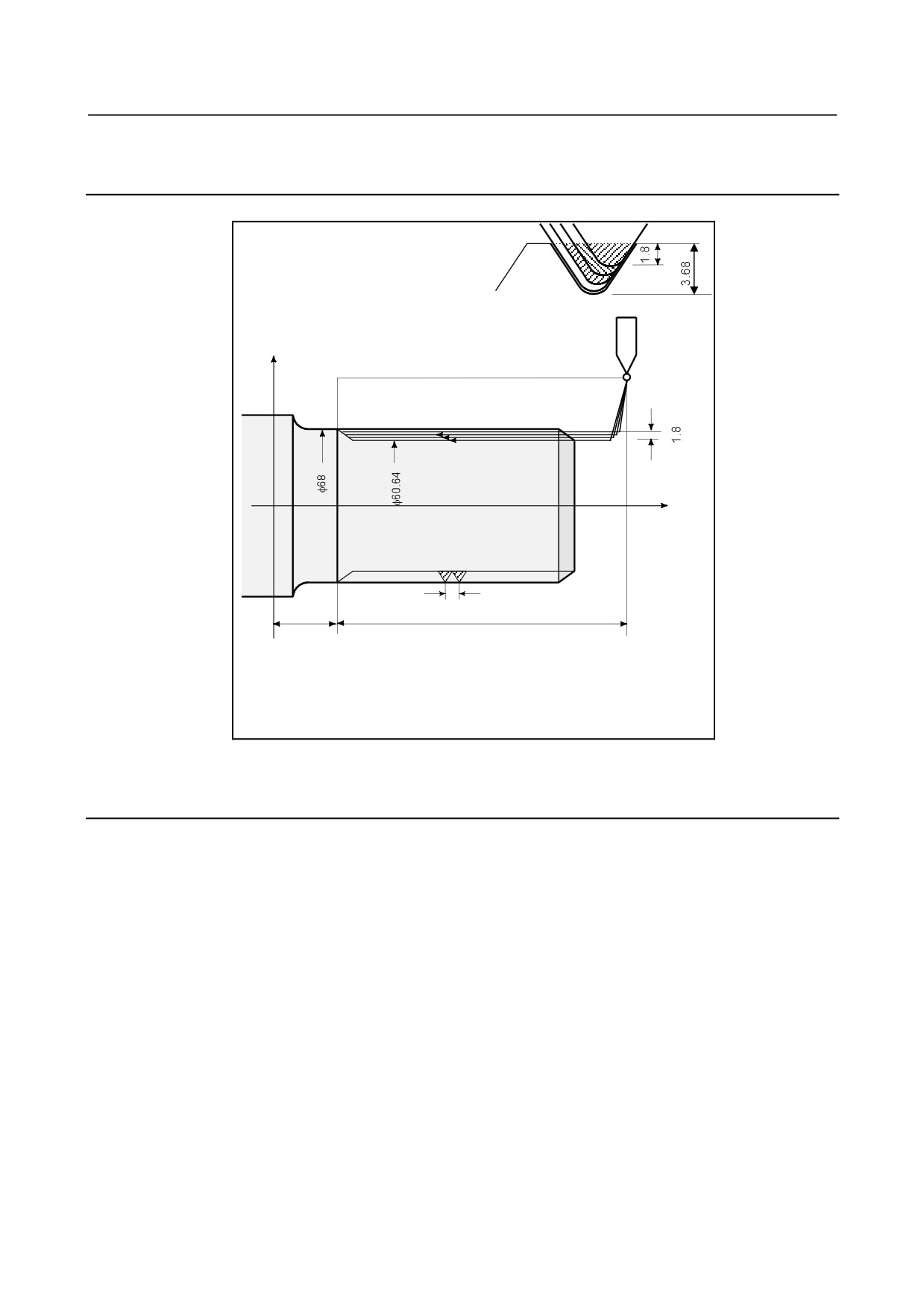
Example
X axis
Z axis
0
6
25
105
G80 X80.0 Z130.0;
G76.7 P011060 Q100 R200 ;
G76.7 X60.64 Z25.0 P3680 Q1800 F6.0 ;
5.8.8
Restrictions on Multiple Repetitive Cycle (G70.7, G71.7, G72.7,
G73.7, G74.7, G75.7, and G76.7)
Programmed commands
-
Program memory
Programs using G70.7, G71.7, G72.7, or G73.7 must be stored in the program memory. The use of the
mode in which programs stored in the program memory are called for operation enables these programs to
be executed in other than the MEM mode. Programs using G74.7, G75.7, or G76.7 need not be stored in
the program memory.
-
Blocks in which data related to a multiple repetitive cycle is specified
The addresses P, Q, X, Z, U, W, and R should be specified correctly for each block.
In a block in which G70.7, G71.7, G72.7, or G73.7 is specified, the following functions cannot be
specified:
• Custom macro calls (simple call, modal call, and subprogram call)
-
Blocks in which data related to a target figure is specified
In the block which is specified by address P of a G71.7, G72.7 or G73.7, G00 or G01 code in group 01
should be commanded. If it is not commanded, alarm PS0065 is generated.
- 156 -
5.FUNCTIONS TO SIMPLIFY
B-64484EN-2/02
PROGRAMMING
PROGRAMMING
In blocks with sequence numbers between those specified at P and Q in G70.7, G71.7, G72.7, and G73.7,
the following commands can be specified:
• Dwell (G04)
• G00, G01, G02, and G03
When a circular interpolation command (G02, G03) is used, there must be no radius difference
between the start point and end point of the arc. If there is a radius difference, the target finishing
figure may not be recognized correctly, resulting in a cutting error such as excessive cutting.
• Custom macro branch and repeat command
The branch destination must be between the sequence numbers specified at P and Q, however.
High-speed branch specified by bits 1 and 4 of parameter No. 6000 is invalid. No custom macro call
(simple, modal, or subprogram call) cannot be specified.
When G70.7, G71.7, G72.7, or G73.7 is executed, the sequence number specified by address P and Q
should not be specified twice or more in the same program.
When #1 = 2500 is executed using a custom macro, 2500.000 is assigned to #1. In such a case, P#1 is
equivalent to P2500.
Relation with other functions
-
Manual intervention
While a multiple repetitive cycle (G70.7, G71.7, G72.7, G73.7, G74.7, G75.7, and G76.7) is being
executed, it is possible to stop the cycle and to perform manual intervention.
The setting of manual absolute on or off is effective for manual operation.
-
Interruption type macro
Any interruption type macro program cannot be executed during execution of a multiple repetitive cycle.
-
Program restart and tool retract and recover
These functions cannot be executed in a block in a multiple repetitive cycle.
-
Axis name and second auxiliary functions
Even if address U, V, or W is used as an axis name or second auxiliary function, data specified at address
U, V, or W in a G71.7, G72.7, or G73.7 block is assumed to be that for the multiple repetitive cycle.
-
Tool nose radius compensation
When using tool nose radius compensation, specify a tool nose radius compensation command (G41,
G42) before a multiple repetitive canned cycle command (G70.7, G71.7, G72.7, G73.7) and specify the
cancel command (G40) outside the programs (from the block specified with P to the block specified with
Q) specifying a target finishing figure. If tool nose radius compensation is specified in the program
specifying a target finishing figure, alarm PS0325,
“UNAVAILABLE COMMAND IS IN SHAPE
PROGRAM”, is issued.
- 157 -
6.COMPENSATION FUNCTION
PROGRAMMING
B-64484EN-2/02
6 COMPENSATION FUNCTION
Chapter 6, "COMPENSATION FUNCTION", consists of the following sections:
6.1
TOOL LENGTH COMPENSATION SHIFT TYPES
158
6.2
AUTOMATIC TOOL LENGTH MEASUREMENT (G37)
165
6.3
TOOL OFFSET (G45 TO G48)
168
6.4
OVERVIEW OF CUTTER COMPENSATION (G40-G42)
173
6.5
OVERVIEW OF TOOL NOSE RADIUS COMPENSATION (G40-G42)
178
6.6
DETAILS OF CUTTER OR TOOL NOSE RADIUS COMPENSATION
188
6.7
VECTOR RETENTION (G38)
238
6.8
CORNER CIRCULAR INTERPOLATION (G39)
239
6.9
3-DIMENSIONAL TOOL COMPENSATION (G40, G41)
241
6.10 TOOL COMPENSATION VALUES, NUMBER OF COMPENSATION VALUES, AND
ENTERING VALUES FROM THE PROGRAM (G10)
244
6.11 COORDINATE SYSTEM ROTATION (G68, G69)
247
6.12 GRINDING WHEEL WEAR COMPENSATION
254
6.13 ACTIVE OFFSET VALUE CHANGE FUNCTION BASED ON MANUAL FEED
259
6.14 ROTARY TABLE DYNAMIC FIXTURE OFFSET
262
6.15 TOOL AXIS DIRECTION TOOL LENGTH COMPENSATION
268
6.16 SPINDLE UNIT COMPENSATION, NUTATING ROTARY HEAD TOOL LENGTH
COMPENSATION
276
6.1
TOOL LENGTH COMPENSATION SHIFT TYPES
Overview
A tool length compensation operation can be performed by shifting the program coordinate system: The
coordinate system containing the axis subject to tool length compensation is shifted by the tool length
compensation value. A tool length compensation shift type can be selected with bit 6 (TOS) of parameter
No. 5006 or bit 2 (TOP) of parameter No. 11400. If no move command is specified together with the G43,
G44, or G49 command, the tool will not move along the axis. If a move command is specified together
with the G43, G44, or G49 command, the coordinate system will be shifted first, then the tool will move
along the axis.
One of the following three methods is available, depending on the type of axis that can be subject to tool
length compensation:
• Tool length compensation A
Compensates the value of the tool length on the Z axis.
• Tool length compensation B
Compensates the value of the tool length on one of the X, Y, and Z axis.
• Tool length compensation C
Compensates the value of the tool length on a specified axis.
- 158 -

B-64484EN-2/02
PROGRAMMING
6.COMPENSATION FUNCTION
Format
-
Tool length compensation A
G43 Z_H_;
Shifts the coordinate system along the Z axis by the compensation value, to the + side.
G44 Z_H_;
Shifts the coordinate system along the Z axis by the compensation value, to the - side.
G43 (or G44) : + (or -) side offset at which to start tool length compensation
H_
: Address specifying the tool length compensation value
-
Tool length compensation B
G17 G43 Z_H_;
Shifts the coordinate system along the Z axis by the compensation value, to the + side.
G17 G44 Z_H_;
Shifts the coordinate system along the Z axis by the compensation value, to the - side.
G18 G43 Y_H_;
Shifts the coordinate system along the X axis by the compensation value, to the + side.
G18 G44 Y_H_;
Shifts the coordinate system along the X axis by the compensation value, to the - side.
G19 G43 X_H_;
Shifts the coordinate system along the Y axis by the compensation value, to the + side.
G19 G44 X_H_;
Shifts the coordinate system along the Y axis by the compensation value, to the - side.
G17 (or G18, G19)
: Plane selection
G43 (or G44)
:
+ (or -) side offset at which to start tool length compensation
H_
: Address specifying the tool length compensation value
-
Tool length compensation C
G43 α_H_;
Shifts the coordinate system along a specified axis by the compensation value, to the + side.
G44 α_H_;
Shifts the coordinate system along a specified axis by the compensation value, to the - side.
G43 (or G44) : + (or -) side offset at which to start tool length compensation
α_
: Address of any one axis
H_
: Address specifying the tool length compensation value
-
Tool length compensation cancel
G49; or H0; Tool length compensation cancel
G49 (or H0)
: Tool length compensation cancel
Explanation
-
Offset direction
If the tool length compensation value specified with an H code (and stored in offset memory) is G43, the
coordinate system is shifted to the + side; if G44, to the - side. If the sign of the tool length compensation
value is -, the coordinate system is shifted to the - side if G43 and to the + side if G44. G43 and G44 are
modal G codes; they remain valid until another G code in the same group is used.
-
Specifying a tool length compensation value
The tool length compensation value corresponding to the number (offset number) specified with an H
code (and stored in offset memory) is used. The tool length compensation corresponding to the offset
number 0 always means 0. It is not possible to set a tool length compensation value corresponding to H0.
- 159 -
6.COMPENSATION FUNCTION
PROGRAMMING
B-64484EN-2/02
-
Compensation axis
Specify one of tool length compensation types A, B, and C, using bits 0 (TLC) and 1 (TLB) of parameter
No. 5001.
-
Specifying offset on two or more axes
Tool length compensation B enables offset on two or more axes by specifying offset axes in multiple
blocks.
To perform offset on X and Y axes
G19 G43 H_; Performs offset on the X axis.
G18 G43 H_; Performs offset on the Y axis.
Tool length compensation C suppresses the generation of an alarm even if offset is performed on two or
more axes at the same time, by setting bit 3 (TAL) of parameter No. 5001 to 1.
-
Tool length compensation cancel
To cancel offset, specify either G49 or H0. Canceling offset causes the shifting of the coordinate system
to be undone. If no move command is specified at this time, the tool will not move along the axis.
Limitation
-
Operation to be performed at the start and cancellation of tool length
compensation
When a tool length compensation shift type is used (bit 6 (TOS) of parameter No. 5006 = 1 or bit 2 (TOP)
of parameter No. 11400 = 1), and if the start or cancellation of a tool length compensation or other
command(*2) is specified in cutter compensation or other mode(*1), look-ahead of the subsequent blocks
is not performed until the end of the block in which the start or cancellation is specified. Thus, the
operation is as described below.
• In the block in which the start or cancellation is specified, deceleration to a stop is performed.
• Because look-ahead is not performed, the compensation vector of cutter compensation is vertical to
the block immediately preceding the one in which the start or cancellation is specified. Thus,
overcutting or undercutting may occur before or after this command.
• Until the completion of the block in which the start or
cancellation is specified, the subsequent custom macros will not
be executed.
*1 Look-ahead of blocks is not performed with the commands below.
•
G code of group 07 other than G40
(in each of cutter compensation (G41/G42) mode and
3-dimensional cutter compensation (G41.2/G42.2/
G41.3/G41.4/G42.4/G41.5/G42.5/G41.6/G42.6) mode)
•
In smooth interpolation (G05.1Q2) mode
*2 The commands below are included:
•
Tool length compensation (G43/G44)
•
Tool length compensation in tool axis direction (G43.1)
•
Tool center point control (G43.4/G43.5)
- 160 -
B-64484EN-2/02
PROGRAMMING
6.COMPENSATION FUNCTION
Example in which overcutting occurs in cutter compensation)
Overcutting may occur if tool length compensation is started or canceled in cutter compensation mode.
:
G40 G49 G00 G90 X0 Y0 Z100. ;
N1 G42 G01 X10. Y10. F500 D1 ;
Start of cutter compensation
N2 G43 Z0. H2 ;
Start of tool length compensation
N3 X100. ;
N4 Y100. ;
N5 X10. ;
N6 Y10. ;
N7 G49 Z100. ;
Cancellation of tool length compensation
N8 #100=#5023 ;
Custom macro command
N9 G40 X0 Y0 ;
Cancellation of cutter compensation
:
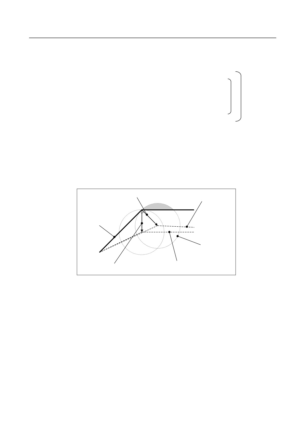
N2 contains G43 (start of tool length compensation) in cutter compensation (G42) mode and, therefore,
look-ahead of N3 and subsequent blocks is not performed.
As a result,
• Deceleration to a stop is performed between N2 and N3.
• The cutter compensation vector at the end point of N1 is vertical to block N1.
(Overcutting may occur.)
If it is assumed that look-ahead is performed, the vector is vertical to the start point of N2, and no
overcutting occurs.
Cutter compensation vector if look-ahead is not
Tool center path if look-ahead
performed
is not performed
Path specified by the
program
Tool
Tool center path if look-ahead is
Cutter compensation vector if
performed
look-ahead is performed
N7 contains G49 (cancellation of tool length compensation) in G42 mode and, therefore, look-ahead of
N8 and subsequent blocks is not performed.
As a result,
• Deceleration to a stop is performed at the end point of N7.
• The custom macro command in N8 is executed after the end of N7. This means that in this example,
variable #100 will be the machine coordinate on the Z-axis at the end point position of N7. (Variable
#5023: Machine coordinate on the third axis)
If it is assumed that look-ahead is performed, N8 is executed at the point the look-ahead of N8 is
performed, that is, before the end of N7, so that variable #100 will be a position before the end point
of N7.
• The cutter compensation vector at the end point of N6 is vertical to block N6.
(Overcutting or undercutting may occur.)
- 161 -
6.COMPENSATION FUNCTION
PROGRAMMING
B-64484EN-2/02
Example in which no overcutting occurs in cutter compensation (recommended)
Before cutter compensation mode, start tool length compensation.
:
G40 G49 G00 G90 X0 Y0 Z100. ;
N1 G43 G01 Z100. F500 H2 ;
Start of tool length compensation
N2 G42 X10. Y10. D1 ;
Start of cutter compensation
N3 Z0 ;
N4 X100. ;
N5 Y100. ;
N6 X10. ;
N7 Y10. ;
N8 G40 X0 Y0 ;
Cancellation of cutter compensation
N9 G49 Z100. ;
Cancellation of tool length compensation
N10 #100=#5023 ;
Custom macro command
:
N1 contains a command to start tool length compensation, but because the mode is not included in "*1"
above, look-ahead of N2 and subsequent blocks is performed. As a result, the cutter compensation path
can be determined correctly. In blocks N1 and N9, deceleration to a stop is not performed. The custom
macro command in N10 is executed without waiting for the end of N9.
-
Operation to be performed if the tool length compensation is changed in tool
length compensation mode
When a tool length compensation shift type is used (bit 6 (TOS) of parameter No. 5006 = 1 or bit 2 (TOP)
of parameter No. 11400 = 1), it is possible to select the operation to be performed if the tool length
compensation is changed(*3) in cutter compensation or other mode(*1) and in tool length or other
mode(*2), by using bit 1 (MOF) of parameter No. 5000.
• Bit 1 (MOF) of parameter No. 5000 = 0
The tool moves along the axis by the change in tool length compensation.
• Bit 1 (MOF) of parameter No. 5000 = 1:
After the tool length compensation is changed, movement by the change in tool length compensation
is not performed until the absolute command for the compensation axis is executed.
*1 The commands below are included:
G code of group 07 other than G40
(in each of cutter compensation
(G41/G42) mode and
3-dimensional cutter compensation
(G41.2/G42.2 / G41.3 / G41.4/G42.4 / G41.5/G42.5 / G41.6/G42.6) mode)
In smooth interpolation (G05.1Q2) mode
*2 The commands below are included:
Tool length compensation (G43/G44)
Tool length compensation in tool axis direction (G43.1)
Tool center point control (G43.4/G43.5)
*3 Changes in tool length compensation include:
•
H code specified in a program (D code for the lathe system extended tool selection function)
•
G43/G44 specified so that the direction of tool length compensation is changed
•
Change in tool compensation made on the offset screen, with a G10 command, a system
variable, a window function, etc. with bit 6 (EVO) of parameter No. 5001 being 1.
•
Restoration of the tool length compensation vector temporarily canceled with G53, G28, G30,
or G30.1 during tool length compensation
- 162 -
B-64484EN-2/02
PROGRAMMING
6.COMPENSATION FUNCTION
Example in which the tool length compensation is changed with an H code)
The following explains the operation to be performed if the offset number is changed in tool length
compensation mode.
:
G40 G49 G00 G90 X0 Y0 Z100. ;
N1 G43 G01 Z100. F500 H2 ;
Start of tool length compensation
N2 G42 X10. Y10. D1 ;
Start of cutter compensation
N3 Z0 ;
N4 X100. ;
N5 Y100. ;
N6 H3 ;
Tool length compensation (number) change
N7 X10. ;
N8 Y10. ;
N9 G91Z-5. ;
Incremental command for the compensation axis
N10 G90 Z-5. ;
Absolute command for the compensation axis
:
In N6, a tool length compensation change (H code) is specified in cutter compensation (G42) mode and
tool length compensation (G43) mode. The operation to be performed in this case is as described below,
depending on the setting of bit 1 (MOF) of parameter No. 5000.
• Bit 1 (MOF) of parameter No. 5000 = 0:
In block N6, the tool moves along the axis by the change in tool length compensation.
• Bit 1 (MOF) of parameter No. 5000 = 1:
In block N6, no movement is performed.
Block N9 contains an incremental command and, therefore, the movement by the tool length
compensation change is not performed. The tool moves by the travel distance specified in the
program (-5.000).
Block N10 contains the absolute command for the compensation axis that is specified first after the
tool length compensation change and, therefore, the tool length compensation change is reflected in
this block.
Example in which the tool length compensation is overwritten during operation)
The following explains the operation to be performed if continuous operation is executed with the
program below, with bit 6 (EVO) of parameter No. 5001 being 1, and tool compensation No. 2 is changed
during the execution of N3.
:
G40 G49 G00 G90 X0 Y0 Z100. ;
N1 G43 G01 Z100. F500 H2 ;
Start of tool length compensation
N2 G42 X10. Y10. D1 ;
Start of cutter compensation
N3 Z0 ;
Change tool length compensation (No. 2) during execution
N4 X100. ;
N5 Y100. ;
N6 X10. ;
N7 Y10. ;
N8 G91Z-5. ;
Incremental command for the compensation axis
N9 G90 Z-5. ;
Absolute command for the compensation axis
:
• Bit 1 (MOF) of parameter No. 5000 = 0:
In N6 (first buffered block after the tool compensation is changed), the tool moves along the axis by
the change in tool length compensation.
• Bit 1 (MOF) of parameter No. 5000 = 1:
- 163 -
6.COMPENSATION FUNCTION
PROGRAMMING
B-64484EN-2/02
Block N6 is the first block after the tool compensation is changed, but this block does not contain a
compensation axis command, and the movement by the change in tool length compensation is not
performed.
Block N8 contains a compensation axis command, but the command is an incremental one, and the
movement by the change in tool length compensation is not performed. The tool moves by the travel
distance specified in the program (-5.000).
Block N9 contains the first absolute command for the compensation axis that is specified after the
tool length compensation is changed and, therefore, the movement by the change in tool length
compensation is performed in this block.
CAUTION
1
Specifying tool length compensation (a shift type) first and then executing an
incremental programming causes the tool length compensation value to be
reflected in the coordinates only, not in the travel distance of the machine;
executing an absolute programming causes the tool length compensation value
to be reflected in both the movement of the machine and the coordinates.
2
If a programmable mirror image is effective, the tool length compensation is
applied in the specified direction.
3
No scaling magnification is applied to the tool length compensation value.
4
No coordinate system rotation is applied to the tool length compensation value.
Tool length compensation is effective in the direction in which the offset is
applied.
5
3-dimensional coordinate conversion is applied to tool length compensation. If
tool length compensation is made effective to multiple axes, the tool length
compensation must be canceled for one axis at a time.
6
With the WINDOW command, changing bit 6 (TOS) of parameter No. 5006 or bit
2 (TOP) of parameter No. 11400 during automatic operation does not cause the
tool length compensation type to be changed.
7
If offset has been performed on two or more axes with tool length compensation
B, a G49 command causes the offset to be canceled on all axes; H0 causes the
offset to be canceled only on the axis vertical to the specified plane.
8
If the tool length compensation value is changed by changing the offset number,
this simply means that the value is replaced by a new tool length compensation
value; it does not mean that a new tool length compensation value is added to
the old tool length compensation.
9
If reference position return (G28, G30, or G30.1) has been specified, tool length
compensation is canceled for the axis specified at the time of positioning on the
reference point; however, tool length compensation is not canceled for an
un-specified axis. If reference position return has been specified in the same
block as that containing tool length compensation cancel (G49), tool length
compensation is canceled for both the specified and un-specified axes at the
time of positioning on the mid-point.
10 With a machine coordinate system command (G53), tool length compensation is
canceled for the axis specified at the time of positioning on the specified point.
11 The tool length compensation vector canceled by specifying G53, G28, G30, or
G30.1 during tool length compensation is restored as described below:
• For tool length compensation types A and B, if bit 6 (EVO) of parameter No.
5001 is 1, the vector is restored in the block buffered next; for all of tool
length compensation types A, B, and C, it is restored in a block containing an
H, G43, or G44 command if parameter is 0.
- 164 -
B-64484EN-2/02
PROGRAMMING
6.COMPENSATION FUNCTION
CAUTION
12 When a tool length compensation shift type is used, if the start or cancellation of
a tool length compensation or other command is specified tool radius ⋅ tool nose
radius compensation mode, look-ahead is not performed. As a result, overcutting
or undercutting may occur before or after the block in which the start or
cancellation is specified. Thus, specify the start and cancellation of tool length
compensation before the entry to tool radius ⋅ tool nose radius compensation
mode or at a location where machining is not affected.
6.2
AUTOMATIC TOOL LENGTH MEASUREMENT (G37)
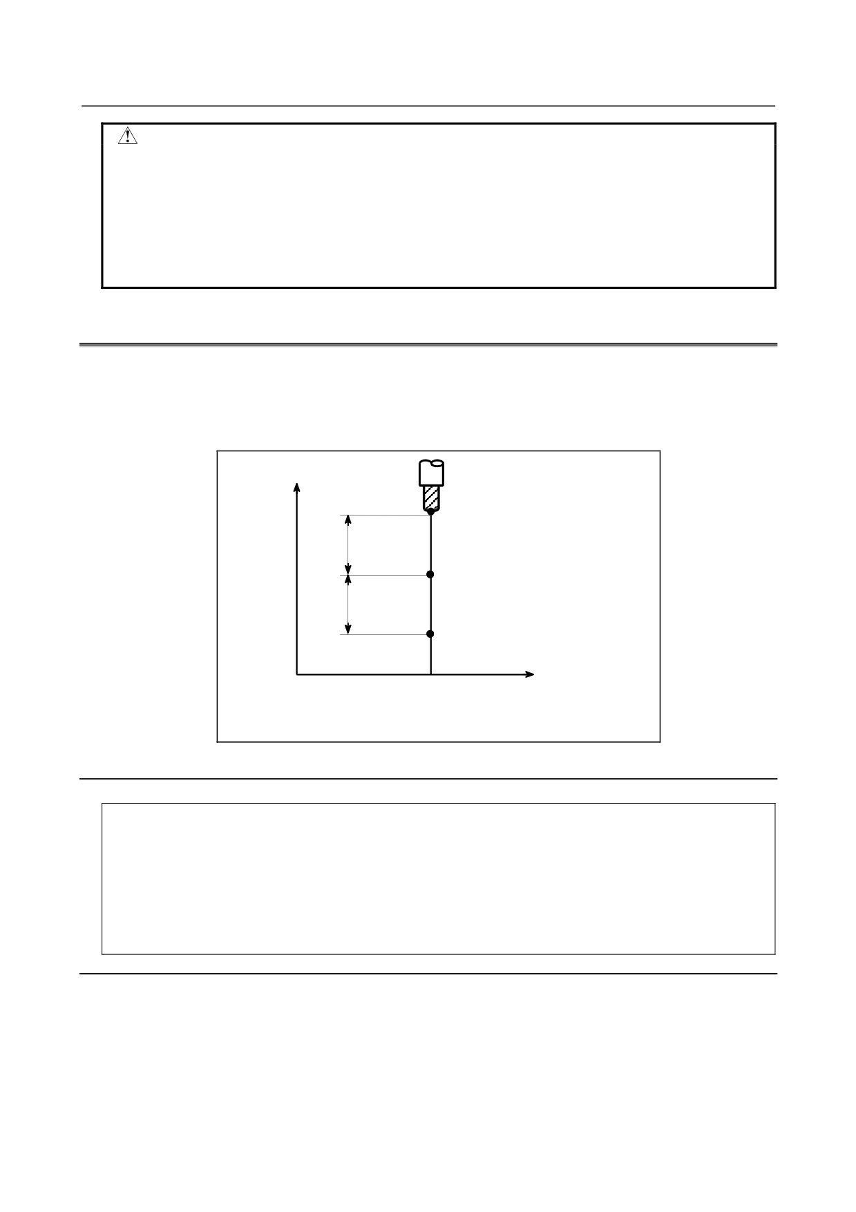
By issuing G37 the tool starts moving to the measurement position and keeps on moving till the approach
end signal from the measurement device is output. Movement of the tool is stopped when the tool nose
reaches the measurement position.
Difference between coordinate value when tool reaches the measurement position and coordinate value
commanded by G37 is added to the tool length compensation amount currently used.
Z
A (Start point)
Rapid
Measurement position is commanded
traverse
with G37
B (Deceleration position)
Measurement
feedrate
C (Measurement position)
The tool stops when the approach end
signal goes on.
X
0
Compensation value = (Current compensation value) + [(Coordinates of the
point at which the tool is stopped) - (Coordinates of the programmed measure
ment position)]
Fig. 6.2 (a) Automatic tool length measurement
Format
G92 IP_ ;
Sets the workpiece coordinate system.
(It can be set with G54 to G59. See Chapter "Coordinate System" in
OPERATOR’S MANUAL (Common to T/M series.))
Hxx ;
Specifies an offset number for tool length compensation.
G90 G37 IP_ ; Absolute programming
G37 is valid only in the block in which it is specified.
IP_ indicates the X-, Y-, Z-, or fourth axis.
Explanation
-
Setting the workpiece coordinate system
Set the workpiece coordinate system so that a measurement can be made after moving the tool to the
measurement position. The coordinate system must be the same as the workpiece coordinate system for
programming.
-
Specifying G37
Specify the absolute coordinates of the correct measurement position.
- 165 -
6.COMPENSATION FUNCTION
PROGRAMMING
B-64484EN-2/02
Execution of this command moves the tool at the rapid traverse rate toward the measurement position,
reduces the federate halfway, then continuous to move it until the approach end signal from the measuring
instrument is issued. When the tool nose reaches the measurement position, the measuring instrument
sends an approach end signal to the CNC which stops the tool.
-
Changing the offset value
The difference between the coordinates of the position at which the tool reaches for measurement and the
coordinates specified by G37 is added to the current tool length compensation value. (If bit 6 (MDC) of
parameter No. 6210 is 1, it is subtracted.)
Offset value =
(Current compensation value)
+ [(Coordinates of the position at which the tool reaches for
measurement) - (Coordinates specified by G37)]
These offset values can be manually changed from MDI.
-
Alarm
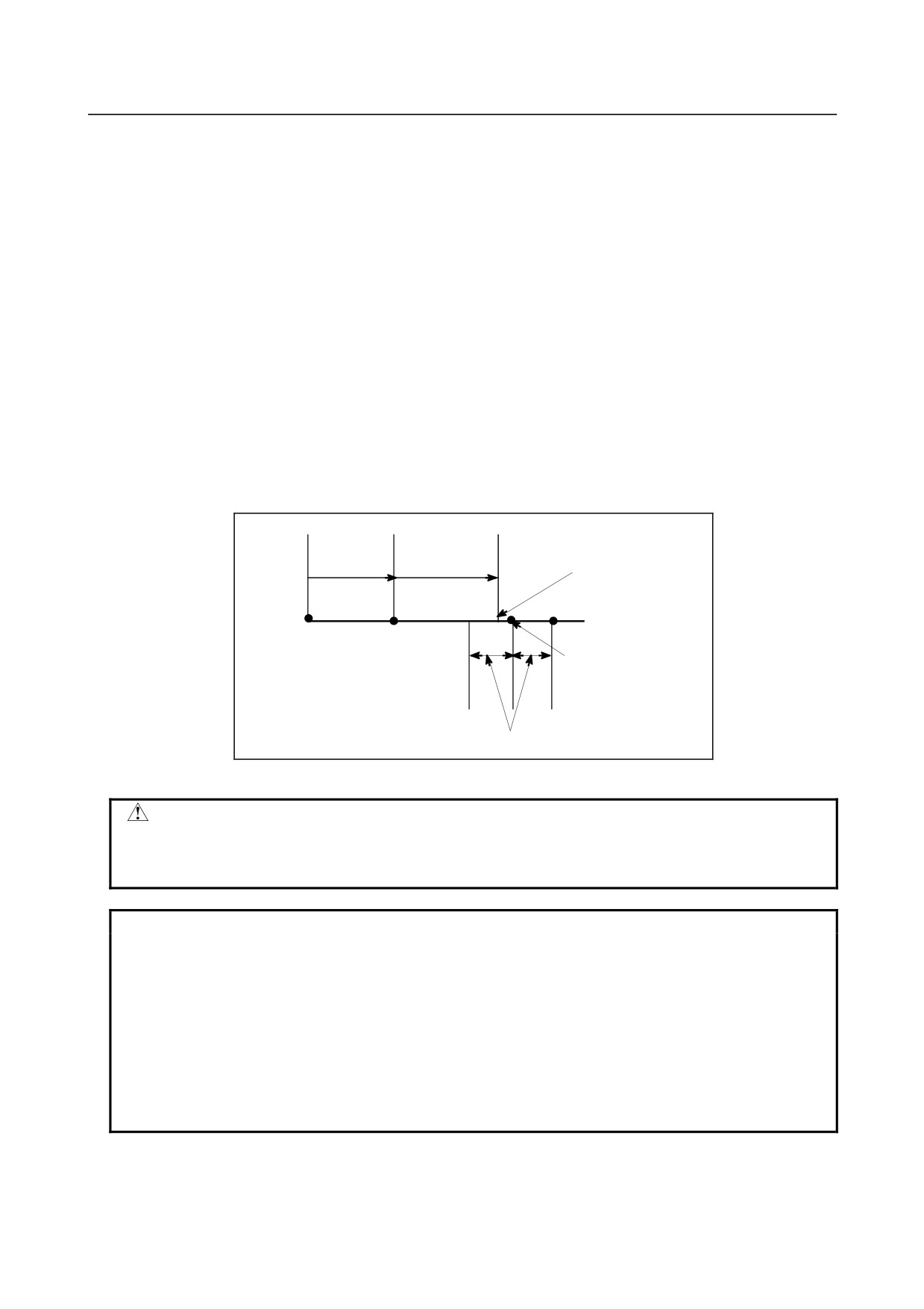
When automatic tool length measurement is executed, the tool moves as shown in Fig. 6.2 (b). If the
approach end signal turns 1 while the tool is traveling from point B to point C, an alarm occurs. Unless
the approach end signal turns 1 before the tool reaches point F, the same alarm occurs. The alarm number
is PS0080.
Deceleration
feedrate
Rapid
(measurement
Approach end signal ON
traverse
feedrate)
A
B
Start
C
D
E F
point
Position commanded
by G37
Permitted range of approach end signal
Fig. 6.2 (b) Tool movement to the measurement position
WARNING
When a manual movement is inserted into a movement at a measurement
federate, return the tool to the position before the inserted manual movement for
restart.
NOTE
1 When an H code is specified in the same block as G37, an alarm is generated.
Specify H code before the block of G37.
2 The measurement speed (FP), γ, and ε are set as parameters (FP: No. 6241, γ:
No. 6251, ε: No. 6254) by the machine tool builder. Make settings so that e are
always positive and γ are always greater than ε.
3 When tool offset memory A is used, the offset value is changed. When tool offset
memory B is used, the tool wear compensation value is changed. When tool
offset memory C is used, the tool wear compensation value for the H code is
changed.
- 166 -
B-64484EN-2/02
PROGRAMMING
6.COMPENSATION FUNCTION
NOTE
4 A delay or variation in detection of the measurement position arrival signal is 0 to
2 msec on the CNC side excluding the PMC side (0.1 msec or less for
high-speed measurement position arrival signal input (optional)). Therefore, the
measurement error is the sum of 2 msec and a delay or variation (including a
delay or variation on the receiver side) in propagation of the skip signal on the
PMC side, multiplied by the feedrate set in parameter No. 6241.
5 A delay or variation in time after detection of the measurement position arrival
signal until a feed stops is 0 to 8 msec. To calculate the amount of overrun,
further consider a delay in acceleration/deceleration, servo delay, and delay on
the PMC side.
Example
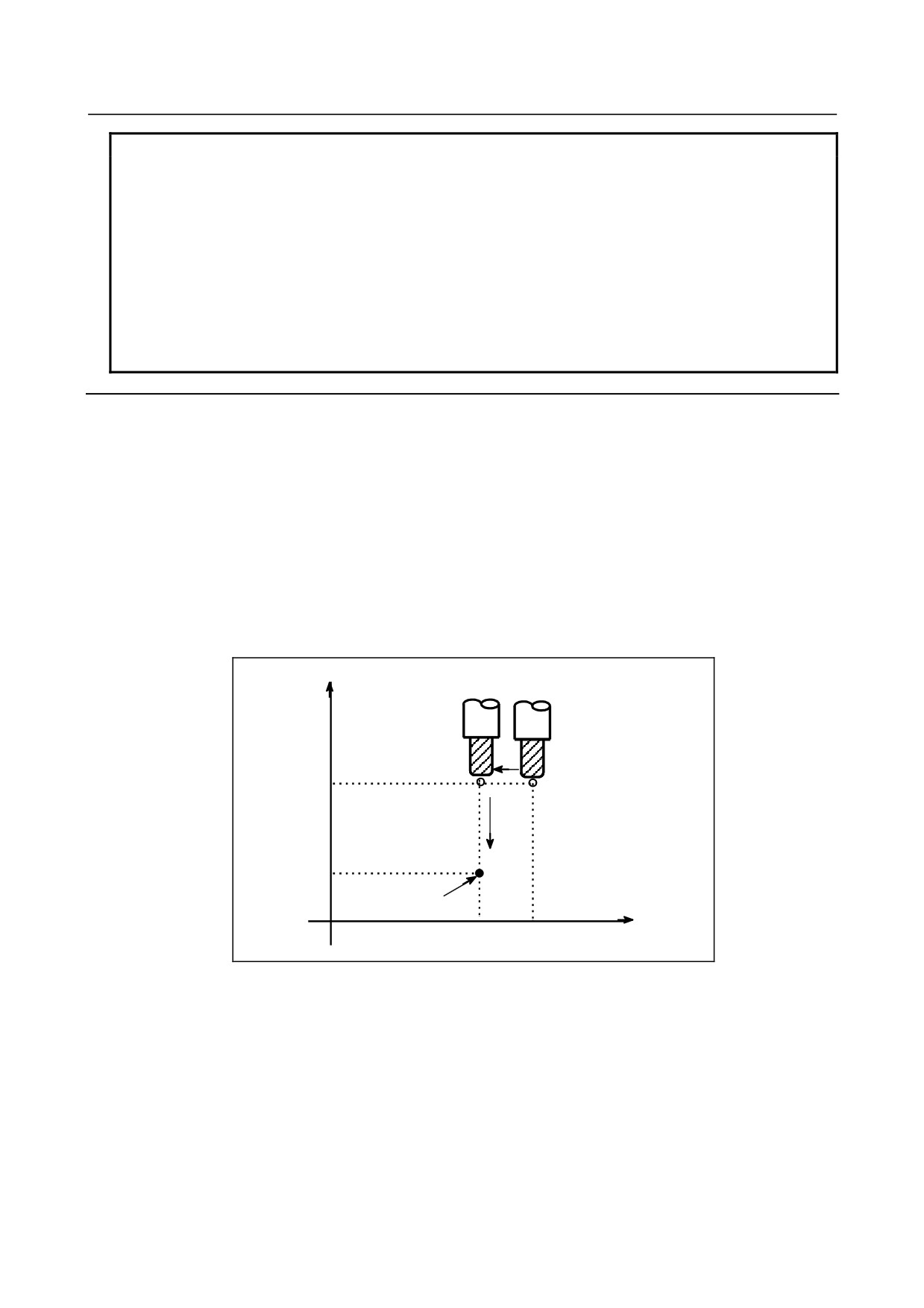
G92 Z760.0 X1100.0 ; Sets a workpiece coordinate system with respect to the programmed absolute
zero point.
G00 G90 X850.0 ;
Moves the tool to X850.0.
That is the tool is moved to a position that is a specified distance from the
measurement position along the Z-axis.
H01 ;
Specifies offset number 1.
G37 Z200.0 ;
Moves the tool to the measurement position.
G00 Z204.0 ;
Retracts the tool a small distance along the Z-axis.
For example, if the tool reaches the measurement position with Z198.0;, the compensation value must be
corrected. Because the correct measurement position is at a distance of 200 mm, the compensation value
is lessened by 2.0 mm (198.0 - 200.0 = -2.0).
Z
760
200
Measurement
position along Z axis
0
850
1100
X
- 167 -
6.COMPENSATION FUNCTION
PROGRAMMING
B-64484EN-2/02
6.3
TOOL OFFSET (G45 TO G48)
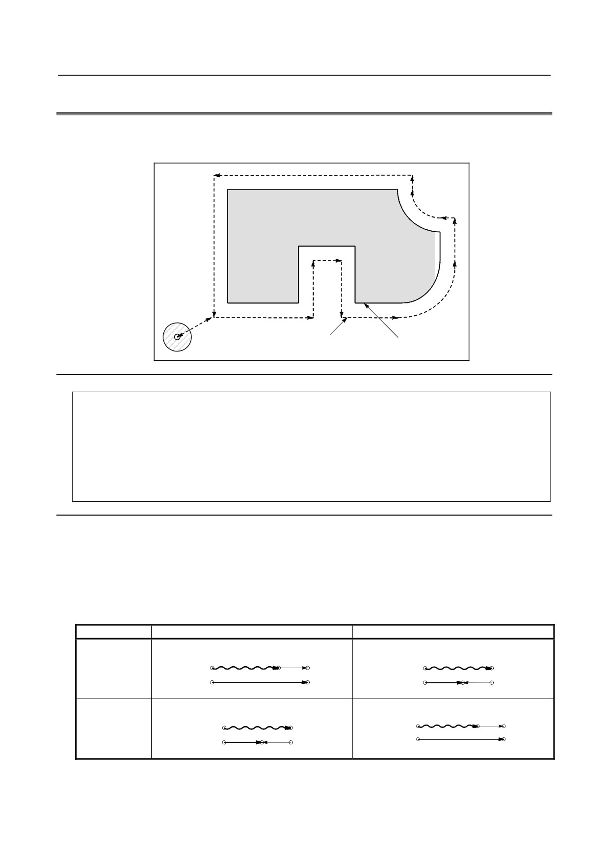
The programmed travel distance of the tool can be increased or decreased by a specified tool offset value
or by twice the offset value.
The tool offset function can also be applied to an additional axis.
Workpiece
Tool center path
Programmed path
Tool
Format
G45 IP_ D_ ; Increase the travel distance by the tool offset value
G46 IP_ D_ ; Decrease the travel distance by the tool offset value
G47 IP_ D_ ; Increase the travel distance by twice the tool offset value
G48 IP_ D_ ; Decrease the travel distance by twice the tool offset value
G45 to 48 : One-shot G code for increasing or decreasing the travel distance
IP_
: Command for moving the tool
D_
Code for specifying the tool offset value
Explanation
-
Increase and decrease
As shown in Table 6.3 (a), the travel distance of the tool is increased or decreased by the specified tool
offset value.
In the absolute mode, the travel distance is increased or decreased as the tool is moved from the end point
of the previous block to the position specified by the block containing G45 to G48.
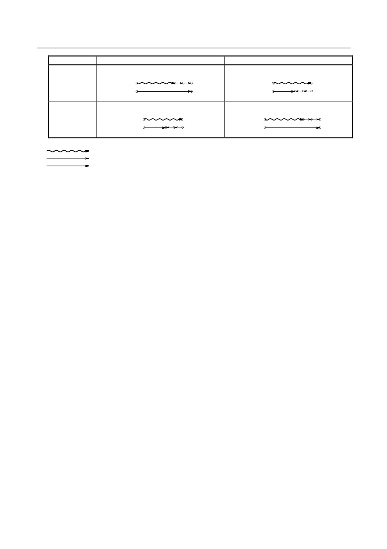
Table 6.3 (a) Increase and decrease of the tool travel distance
G code
When a positive tool offset value is specified
When a negative tool offset value is specified
Start point
End point
Start point
End point
G45
Start point
End point
Start point
End point
G46
- 168 -
B-64484EN-2/02
PROGRAMMING
6.COMPENSATION FUNCTION
G code
When a positive tool offset value is specified
When a negative tool offset value is specified
Start point
End point
Start point
End point
G47
Start point
End point
Start point
End point
G48
Programmed movement distance
Tool offset value
Actual movement position
If a move command with a travel distance of zero is specified in the incremental programming (G91)
mode, the tool is moved by the distance corresponding to the specified tool offset value.
If a move command with a travel distance of zero is specified in the absolute programming (G90) mode,
the tool is not moved.
-
Tool offset value
Once selected by D code, the tool offset value remains unchanged until another tool offset value is
selected.
Tool offset values can be set within the following range:
D0 always indicates a tool offset value of zero.
- 169 -
6.COMPENSATION FUNCTION
PROGRAMMING
B-64484EN-2/02
CAUTION
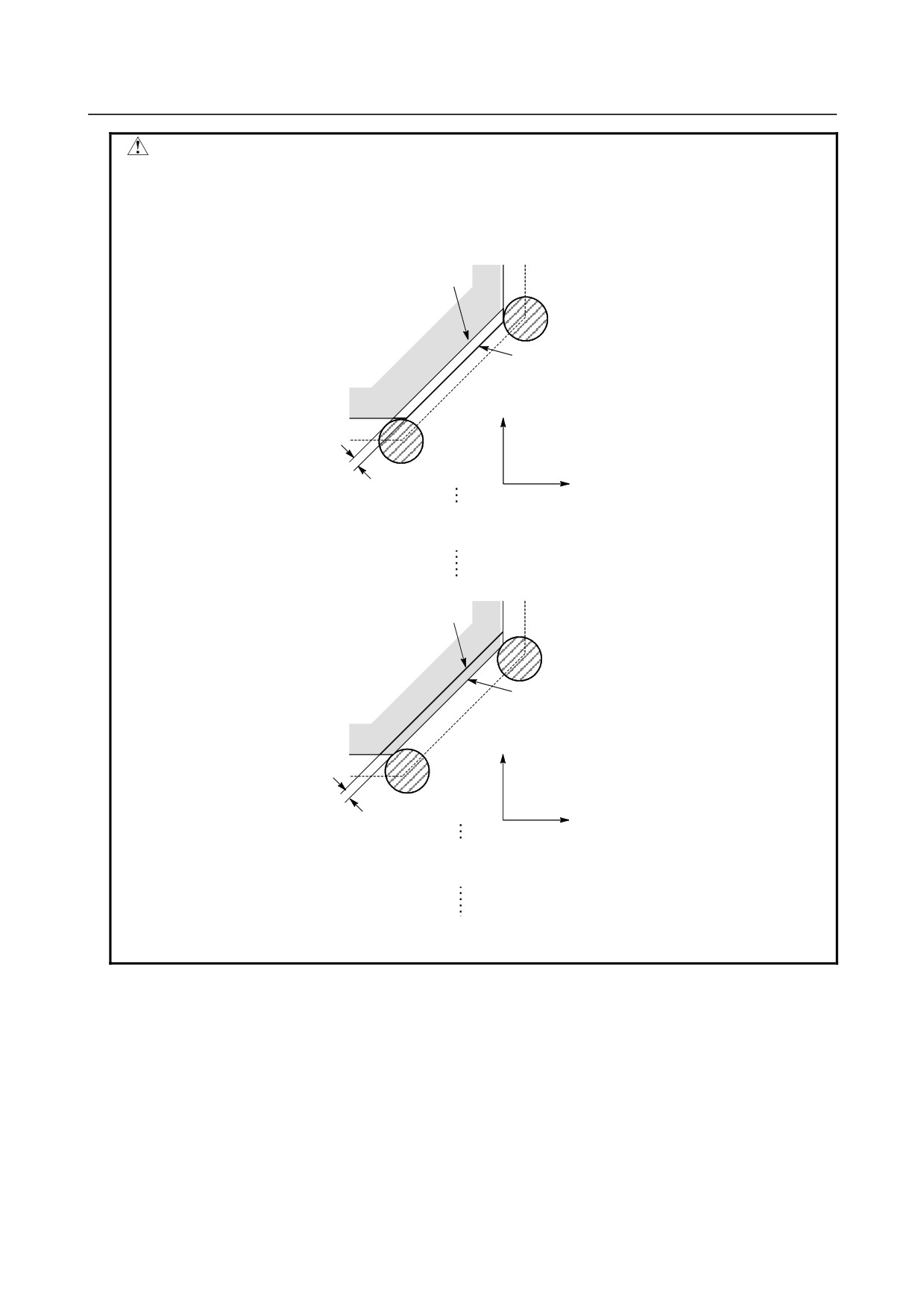
1 When G45 to G48 is specified to n axes (n=1-6) simultaneously in a motion
block, offset is applied to all n axes.
When the cutter is offset only for cutter radius or diameter in taper cutting,
overcutting or undercutting occurs.
Therefore, use cutter compensation (G40 or G42) shown in II-6.4 or 6.6.
Shape actually cut
Desired
shape
Y axis
Overcutting
X axis
G01 X_ F_ ;
G47 X_ Y_ D_ ;
Y_ ;
Desired shape
Shape actually cut
Y axis
Undercutting
X axis
G01 G45 X_ F_ D_;
X_ Y_ ;
G45 Y_ ;
2 G45 to G48 (tool offset) must not be used in the G41 or G42 (cutter
compensation) mode.
- 170 -
B-64484EN-2/02
PROGRAMMING
6.COMPENSATION FUNCTION
NOTE
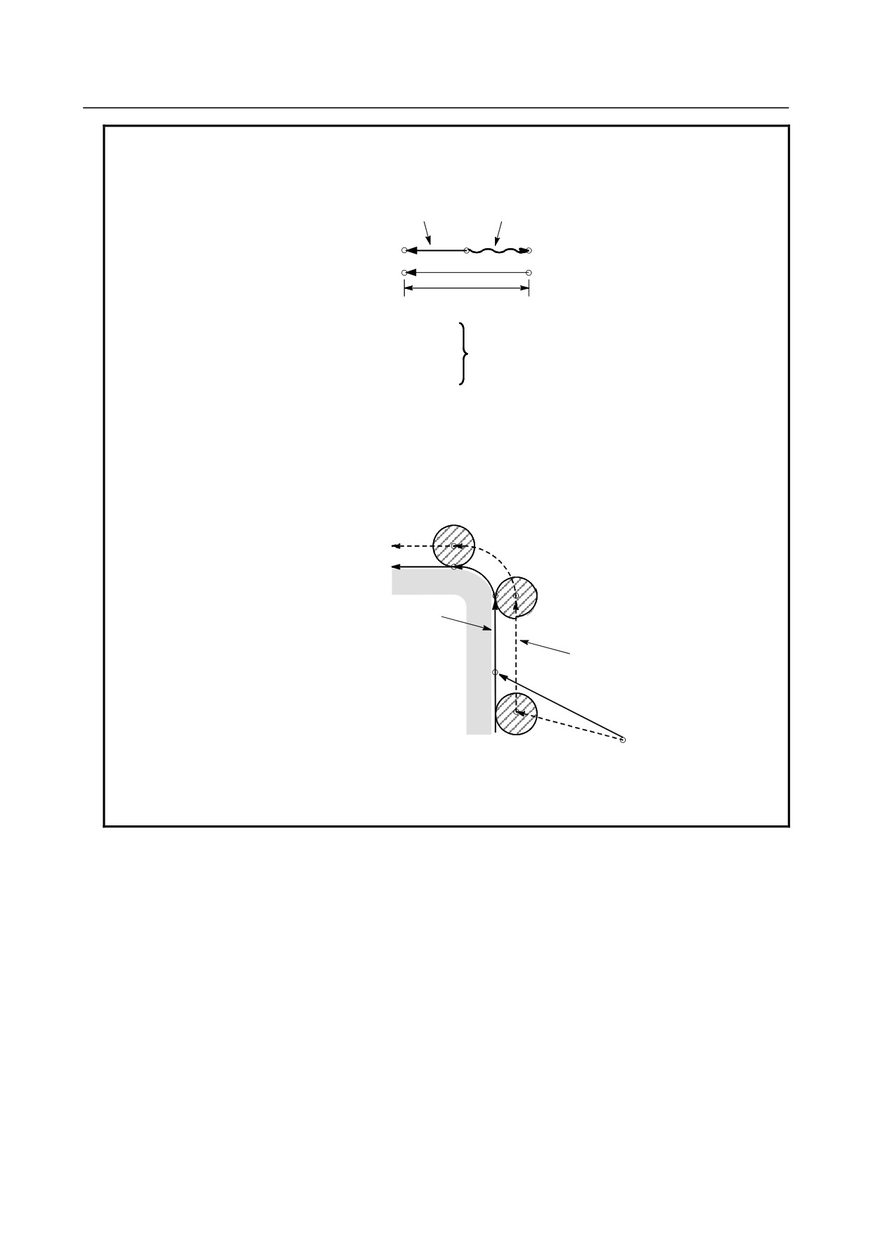
1 When the specified direction is reversed by decrease, the tool moves in the
opposite direction.
Movement of the
Program command
Start
End
position
position
Tool offset value
Example
G46 X2.50 ;
Tool offset value
Equivalent command
+3.70
X-1.20 ;
2
Tool offset can be applied to circular interpolation (G02, G03) with the G45 to
G48 commands only for 1/4 and 3/4 circles using addresses I, J and K by the
parameter setting, providing that the coordinate system rotation be not specified
at the same time. This function is provided for compatibility with the conventional
CNC program without any cutter compensation. The function should not be used
when a new CNC program is prepared.
Tool offset for circular interpolation
N4
N3
Programmed tool path
N2
Program
Actual tool path
N1 G46 G00 X_ Y_ D_ ;
N2 G45 G01 Y_ F_ ;
N1
N3 G45 G03 X_ Y_ I_ ;
N4 G01 X_ ;
3
D code should be used in tool offset mode.
4
G45 to G48 are ignored in canned cycle mode. Perform tool offset by specifying
G45 to G48 before entering canned cycle mode and cancel the offset after
releasing the canned cycle mode.
- 171 -