FANUC Series 30i-MODEL B, 31i-MODEL B, 32i-MODEL B. For Machining Center System. OPERATOR'S MANUAL - page 7
6.COMPENSATION FUNCTION
PROGRAMMING
B-64484EN-2/02
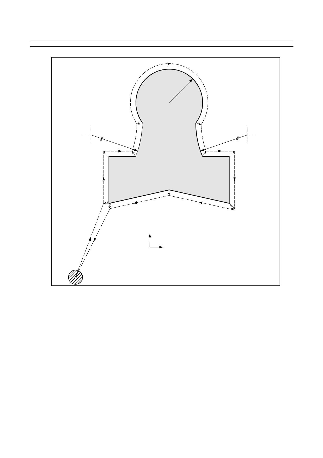
Example
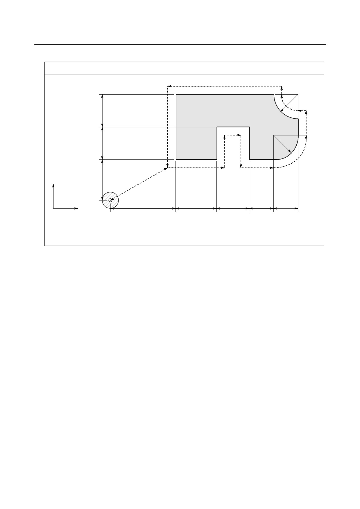
Program using tool offset
N12
N11
30R
N9
40
N10
N13
N8
N4
30R
40
N3
N5
N1
N7
N2
N6
Y axis
50
N14
80
50
40
30
30
X
Origin
Tool diameter
:
20φ
Offset No.
:
01
Tool offset value
:
+10.0
Program
N1 G91 G46 G00 X80.0 Y50.0 D01 ;
N2 G47 G01 X50.0 F120.0 ;
N3 Y40.0 ;
N4 G48 X40.0 ;
N5 Y-40.0 ;
N6 G45 X30.0 ;
N7 G45 G03 X30.0 Y30.0 J30.0 ;
N8 G45 G01 Y20.0 ;
N9 G46 X0 ;
(Decreases toward the positive direction for movement amount "0". The tool moves
in the -X direction by the offset value.)
N10 G46 G02 X-30.0 Y30.0 J30.0 ;
N11 G45 G01 Y0 ; (Increase toward the positive direction for movement amount "0". The tool moves in
the +Y direction by the offset value.)
N12 G47 X-120.0 ;
N13 G47 Y-80.0 ;
N14 G46 G00 X-80.0 Y-50.0 ;
- 172 -
B-64484EN-2/02
PROGRAMMING
6.COMPENSATION FUNCTION
6.4
OVERVIEW OF CUTTER COMPENSATION (G40-G42)
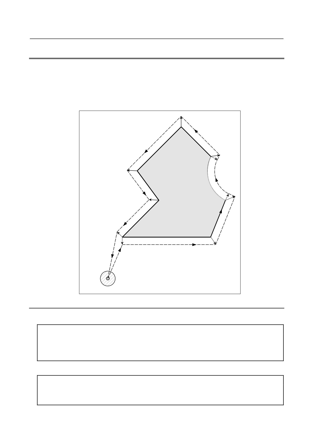
When the tool is moved, the tool path can be shifted by the radius of the tool (Fig. 6.4 (a)).
To make an offset as large as the radius of the tool, CNC first creates an offset vector with a length equal
to the radius of the tool (start-up). The offset vector is perpendicular to the tool path. The tail of the vector
is on the workpiece side and the head positions to the center of the tool.
If a linear interpolation or circular interpolation command is specified after start-up, the tool path can be
shifted by the length of the offset vector during machining.
To return the tool to the start point at the end of machining, cancel the cutter compensation mode.
Cutter
compensation
cancel
Start-up
Fig. 6.4 (a) Outline of cutter compensation
Format
-
Start up (cutter compensation start)
G00(or G01)G41(or G42) IP_D_;
G41 : Cutter compensation left (Group 07)
G42 : Cutter compensation right (Group 07)
IP_
: Command for axis movement
D_
: Code for specifying as the cutter compensation value (1-3 digits) (D code)
-
Cutter compensation cancel (offset mode cancel)
G40 IP_;
G40 : Cutter compensation cancel (Group 07)
(Offset mode cancel)
IP_
: Command for axis movement
- 173 -
6.COMPENSATION FUNCTION
PROGRAMMING
B-64484EN-2/02
-
Selection of the offset plane
Offset plane
Command for plane selection
IP_
XpYp
G17 ;
Xp_Yp_
ZpXp
G18 ;
Xp_Zp_
YpZp
G19 ;
Yp_Zp_
Explanation
-
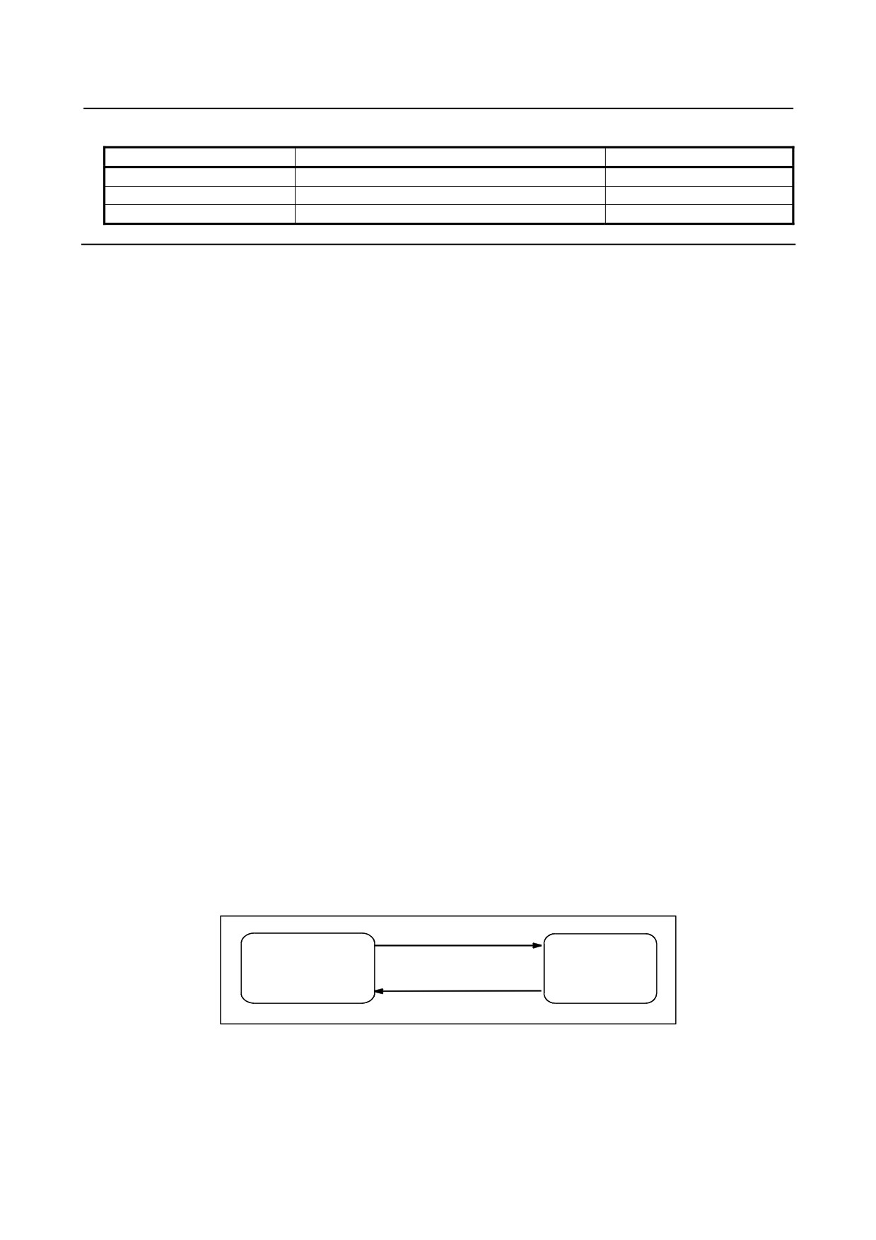
Offset cancel mode
At the beginning when power is applied the control is in the cancel mode. In the cancel mode, the vector
is always 0, and the tool center path coincides with the programmed path.
-
Start-up
When a cutter compensation command (G41 or G42, D code other than 0) is specified in the offset cancel
mode, the CNC enters the offset mode.
Moving the tool with this command is called start-up.
Specify positioning (G00) or linear interpolation (G01) for start-up.
If circular interpolation (G02, G03) or involute interpolation (G02.2, G03.2) is specified, alarm PS0034
occurs.
For the start-up and subsequent blocks, the CNC prereads as many blocks as the number of preread
blocks set in the parameter No. 19625.
-
Offset mode
In the offset mode, compensation is accomplished by positioning (G00), linear interpolation (G01), or
circular interpolation (G02, G03).
If three or more blocks that move the tool cannot be read in offset mode, the tool may make either an
excessive or insufficient cut.
If the offset plane is switched in the offset mode, alarm PS0037 occurs and the tool is stopped.
-
Offset mode cancel
In the offset mode, when a block which satisfies any one of the following conditions is executed, the
CNC enters the offset cancel mode, and the action of this block is called the offset cancel.
1.
G40 has been commanded.
2.
0 has been commanded as the offset number for cutter compensation (D code).
When performing offset cancel, circular arc commands (G02 and G03) and involute commands (G02.2
and G03.2) are not available. If these commands are specified, an PS0034 is generated and the tool stops.
In the offset cancel, the control executes the instructions in that block and the block in the cutter
compensation buffer.
In the meantime, in the case of a single block mode, after reading one block, the control executes it and
stops. By pushing the cycle start button once more, one block is executed without reading the next block.
Then the control is in the cancel mode, and normally, the block to be executed next will be stored in the
buffer register and the next block is not read into the buffer for cutter compensation.
Start up
(G41/G42)
Offset cancel mode
Offset mode
Offset mode cancel
(G40/D0)
Fig. 6.4 (b) Changing the offset mode
-
Change of the cutter compensation value
In general, the cutter compensation value shall be changed in the cancel mode, when changing tools. If
the cutter compensation value is changed in offset mode, the vector at the end point of the block is
calculated for the new cutter compensation value.
- 174 -
B-64484EN-2/02
PROGRAMMING
6.COMPENSATION FUNCTION
Calculated from the cutter
Calculated from the cutter
compensation value in the block N6
compensation value in the block N7
N7
N6
N8
Programmed path
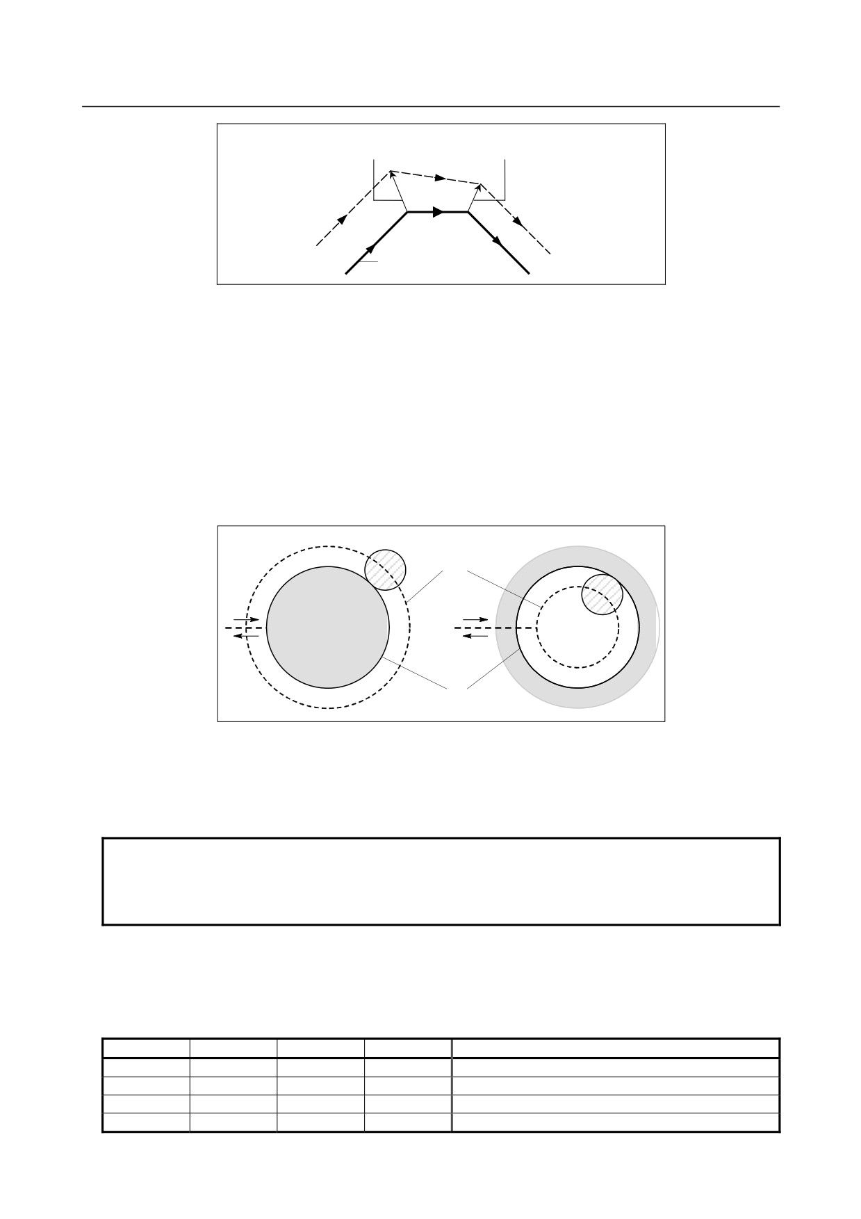
Fig. 6.4 (c) Changing the cutter compensation value
-
Positive/negative cutter compensation value and tool center path
If the compensation value is negative (-), distribution is made for a figure in which G41's and G42's are
all replaced with each other on the program. Consequently, if the tool center is passing around the outside
of the workpiece, it will pass around the inside, and vice versa.
Fig. 6.4 (d) shows one example.
Generally, the compensation value is programmed to be positive (+).
When a tool path is programmed as in <1>, if the compensation value is made negative (-), the tool center
moves as in <2>, and vice versa. Consequently, the same program permits cutting both male and female
shapes, and any gap between them can be adjusted by the selection of the compensation value.
Applicable if start-up and cancel is A type.
(See the descriptions about the start-up of cutter
compensation.)
<1>
<2>
Tool center path
Programmed path
Fig. 6.4 (d) Tool center paths when positive and negative cutter
compensation values are specified
-
Cutter compensation value setting
Assign a cutter compensation values to the D codes on the MDI panel.
NOTE
The cutter compensation value for which the D code corresponds to 0 always
means 0.
It is not possible to set the cutter compensation value corresponding to D0.
-
Valid compensation value range
The valid range of values that can be set as a compensation value is either of the following, depending on
the bits 3 (OFE), 2 (OFD), 1 (OFC), and 0 (OFA) of parameter No. 5042.
Valid compensation range (metric input)
OFE
OFD
OFC
OFA
Range
0
0
0
1
±9999.99 mm
0
0
0
0
±9999.999 mm
0
0
1
0
±9999.9999 mm
0
1
0
0
±9999.99999 mm
- 175 -

6.COMPENSATION FUNCTION
PROGRAMMING
B-64484EN-2/02
OFE
OFD
OFC
OFA
Range
1
0
0
0
±999.999999 mm
Valid compensation range (inch input)
OFE
OFD
OFC
OFA
Range
0
0
0
1
±999.999 inch
0
0
0
0
±999.9999 inch
0
0
1
0
±999.99999 inch
0
1
0
0
±999.999999 inch
1
0
0
0
±99.9999999 inch
The compensation value corresponding to offset No. 0 always means 0. It is not possible to set the
compensation value corresponding to offset No. 0.
-
Offset vector
The offset vector is the two dimensional vector that is equal to the cutter compensation value assigned by
D code. It is calculated inside the control unit, and its direction is up-dated in accordance with the
progress of the tool in each block.
The offset vector is deleted by reset.
-
Specifying a cutter compensation value
Specify a cutter compensation value with a number assigned to it. The number consists of 1 to 3 digits
after address D (D code).
The D code is valid until another D code is specified. The D code is used to specify the tool offset value
as well as the cutter compensation value.
-
Plane selection and vector
Offset calculation is carried out in the plane determined by G17, G18 and G19, (G codes for plane
selection). This plane is called the offset plane.
Compensation is not executed for the coordinate of a position which is not in the specified plane. The
programmed values are used as they are.
In simultaneous 3 axes control, the tool path projected on the offset plane is compensated.
The offset plane is changed during the offset cancel mode. If it is performed during the offset mode, an
PS0037 is displayed and the machine is stopped.
- 176 -
B-64484EN-2/02
PROGRAMMING
6.COMPENSATION FUNCTION
Example
250R
N5
C1(700,1300)
P4(500,1150) P5(900,1150)
C3
(-150,1150)
C2 (1550,1150)
650R
650R
N4
N6
N3
N7
P2
P3(450,900)
P6(950,900)
P7
(250,900)
(1150,900)
N8
N2
P9(700,650)
P1
P8
(250,550)
(1150,550)
N10
N9
Y axis
N1
N11
Unit : mm
X axis
Start point
G17 G92 X0 Y0 Z0 ;
Specifies absolute coordinates.
The tool is positioned at the start point (X0, Y0, Z0).
N1 G90 G00 G41 D07 X250.0 Y550.0 ;
Starts cutter compensation (start-up).
The tool is shifted to the left of the programmed path by the
distance specified in D07.
In other words the tool path is shifted by the radius of the
tool (offset mode) because D07 is set to 15 beforehand (the
radius of the tool is 15 mm).
N2 G01 Y900.0 F150 ;
Specifies machining from P1 to P2.
N3 X450.0 ;
Specifies machining from P2 to P3.
N4 G03 X500.0 Y1150.0 R650.0 ;
Specifies machining from P3 to P4.
N5 G02 X900.0 R-250.0 ;
Specifies machining from P4 to P5.
N6 G03 X950.0 Y900.0 R650.0 ;
Specifies machining from P5 to P6.
N7 G01 X1150.0 ;
Specifies machining from P6 to P7.
N8 Y550.0 ;
Specifies machining from P7 to P8.
N9 X700.0 Y650.0 ;
Specifies machining from P8 to P9.
N10 X250.0 Y550.0 ;
Specifies machining from P9 to P1.
N11 G00 G40 X0 Y0 ;
Cancels the offset mode.
The tool is returned to the start point (X0, Y0, Z0).
- 177 -
6.COMPENSATION FUNCTION
PROGRAMMING
B-64484EN-2/02
6.5
OVERVIEW OF TOOL NOSE RADIUS COMPENSATION
(G40-G42)
The tool nose radius compensation function automatically compensates for the errors due to the tool nose
roundness.
Workpiece
Tool path without compensation
Tool path with compensation
Insufficient
Tool nose
depth of
cutting
R
Shape processed without tool
nose radius compensation
Fig. 6.5 (a) Tool path of tool nose radius compensation
6.5.1
Imaginary Tool Nose
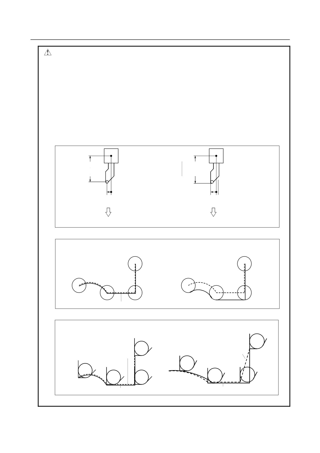
The tool nose at position A in Fig. 6.5.1 (a) does not actually exist.
The imaginary tool nose is required because it is usually more difficult to set the actual tool nose radius
center to the start point than the imaginary tool nose.
Also when imaginary tool nose is used, the tool nose radius need not be considered in programming.
The position relationship when the tool is set to the start point is shown in Fig. 6.5.1 (a).
A
Start position
Start position
When programmed using the tool
When programmed using the
nose center
imaginary tool nose
Fig. 6.5.1 (a) Tool nose radius center and imaginary tool nose
- 178 -
B-64484EN-2/02
PROGRAMMING
6.COMPENSATION FUNCTION
CAUTION
In a machine with reference positions, a standard position like the turret center
can be placed over the start point. The distance from this standard position to
the tool nose radius center or the imaginary tool nose is compensated by the tool
length compensation function.
Setting the distance from the standard position to the tool nose radius center as
the offset value is the same as placing the tool nose radius center over the start
point, while setting the distance from the standard position to the imaginary tool
nose is the same as placing the imaginary tool nose over the standard position.
To set the offset value, it is usually easier to measure the distance from the
standard position to the imaginary tool nose than from the standard position to
the tool nose radius center.
OFX
OFX
(Tool length
(Tool length
compensation in
compensation in
X axis)
X axis)
OFZ
OFZ
(Tool length
(Tool length
compensation
compensation
in Z axis)
in Z axis)
Compensates for the distance from the standard
Compensates for the distance from the standard
position to the tool nose center by the tool length
position to the imaginary tool nose by the tool
compensation
length compensation
The start position is placed over the tool nose center
The start position is placed over the imaginary tool
nose
Fig. 6.5.1 (b) Tool length compensation when the turret center is placed over the start point
Unless tool nose radius compensation is
If tool nose radius compensation is used, accurate
performed, the tool nose center path is the
cutting will be performed.
same as the programmed path.
Start-
Start-
Tool nose center path
Tool nose center path
up
up
Programmed path
Programmed path
Fig. 6.5.1 (c) Tool path when programming using the tool nose center
Without tool nose radius compensation, the
With tool nose radius compensation, accurate
tool nose radius center path is the same as
cutting will be performed.
the programmed path.
Imaginary tool
Imaginary tool
nose path
nose path
Start-
Start-
up
up
Programmed path
Programmed path
Fig. 6.5.1 (d) Tool path when programming using the imaginary tool nose
- 179 -
6.COMPENSATION FUNCTION
PROGRAMMING
B-64484EN-2/02
6.5.2
Direction of Imaginary Tool Nose
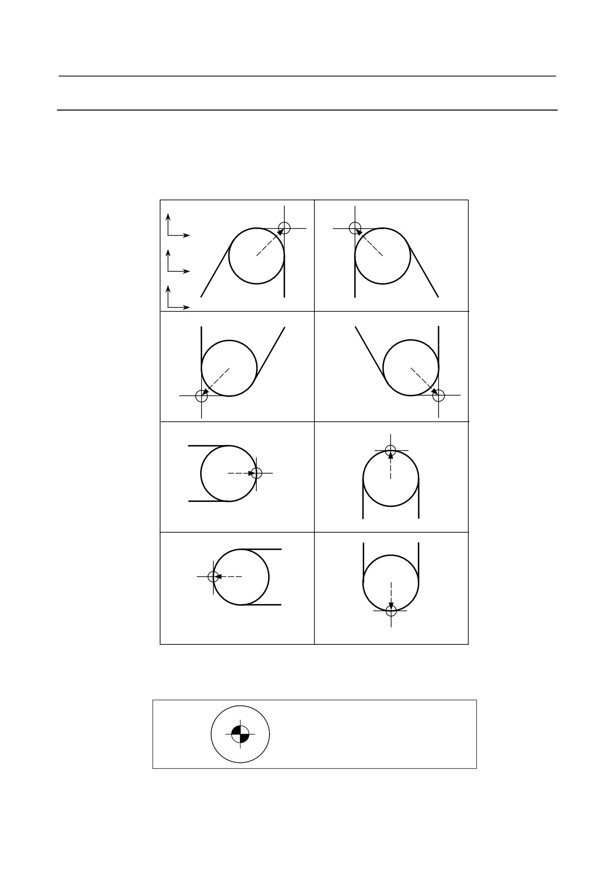
The direction of the imaginary tool nose viewed from the tool nose center is determined by the direction
of the tool during cutting, so it must be set in advance as well as offset values.
The direction of the imaginary tool nose can be selected from the eight specifications shown in the Fig.
6.5.2 (a) below together with their corresponding codes. Fig. 6.5.2 (a) illustrates the relation between the
tool and the start point. The following apply when the tool geometry offset and tool wear offset option are
selected.
X
G18
Z
Y
G17
X
Z
G19
Y
Imaginary tool nose number 1
Imaginary tool nose number 2
Imaginary tool nose
Imaginary tool nose
number 3
number 4
Imaginary tool nose number 5
Imaginary tool nose number 6
Imaginary tool nose number 7
Imaginary tool nose number 8
Fig. 6.5.2 (a) Direction of imaginary tool nose
Imaginary tool nose numbers 0 and 9 are used when the tool nose center coincides with the start point. Set
imaginary tool nose number to address OFT for each offset number.
Imaginary tool nose number 0 or 9
- 180 -
B-64484EN-2/02
PROGRAMMING
6.COMPENSATION FUNCTION
6.5.3
Offset Number and Offset Value
Explanation
-
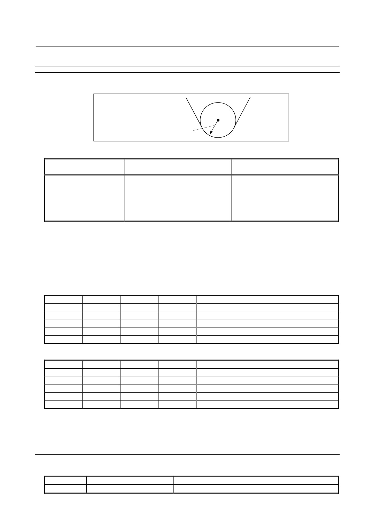
Offset number and offset value
Tool nose radius compensation value
(Tool nose radius value)
Table 6.5.3 (a) Offset number and offset value (example)
Offset number Up to 999
(Tool compensation value)
(Direction of imaginary tool nose)
sets
001
0.200
1
002
0.250
2
003
0.120
6
004
:
:
005
:
:
:
:
:
-
Command of offset value
An offset number is specified with the D code.
-
Setting range of offset value
The range of values that can be set as a compensation value is either of the following, depending on the
bits 3 (OFE), 2 (OFD), 1 (OFC), and 0 (OFA) of parameter No. 5042.
Table 6.5.3 (b) Valid compensation range (metric input)
OFE
OFD
OFC
OFA
Range
0
0
0
1
±9999.99 mm
0
0
0
0
±9999.999 mm
0
0
1
0
±9999.9999 mm
0
1
0
0
±9999.99999 mm
1
0
0
0
±999.999999 mm
Table 6.5.3 (c) Valid compensation range (inch input)
OFE
OFD
OFC
OFA
Range
0
0
0
1
±999.999 inch
0
0
0
0
±999.9999 inch
0
0
1
0
±999.99999 inch
0
1
0
0
±999.999999 inch
1
0
0
0
±99.9999999 inch
The offset value corresponding to the offset number 0 is always 0.
No offset value can be set to offset number 0.
6.5.4
Workpiece Position and Move Command
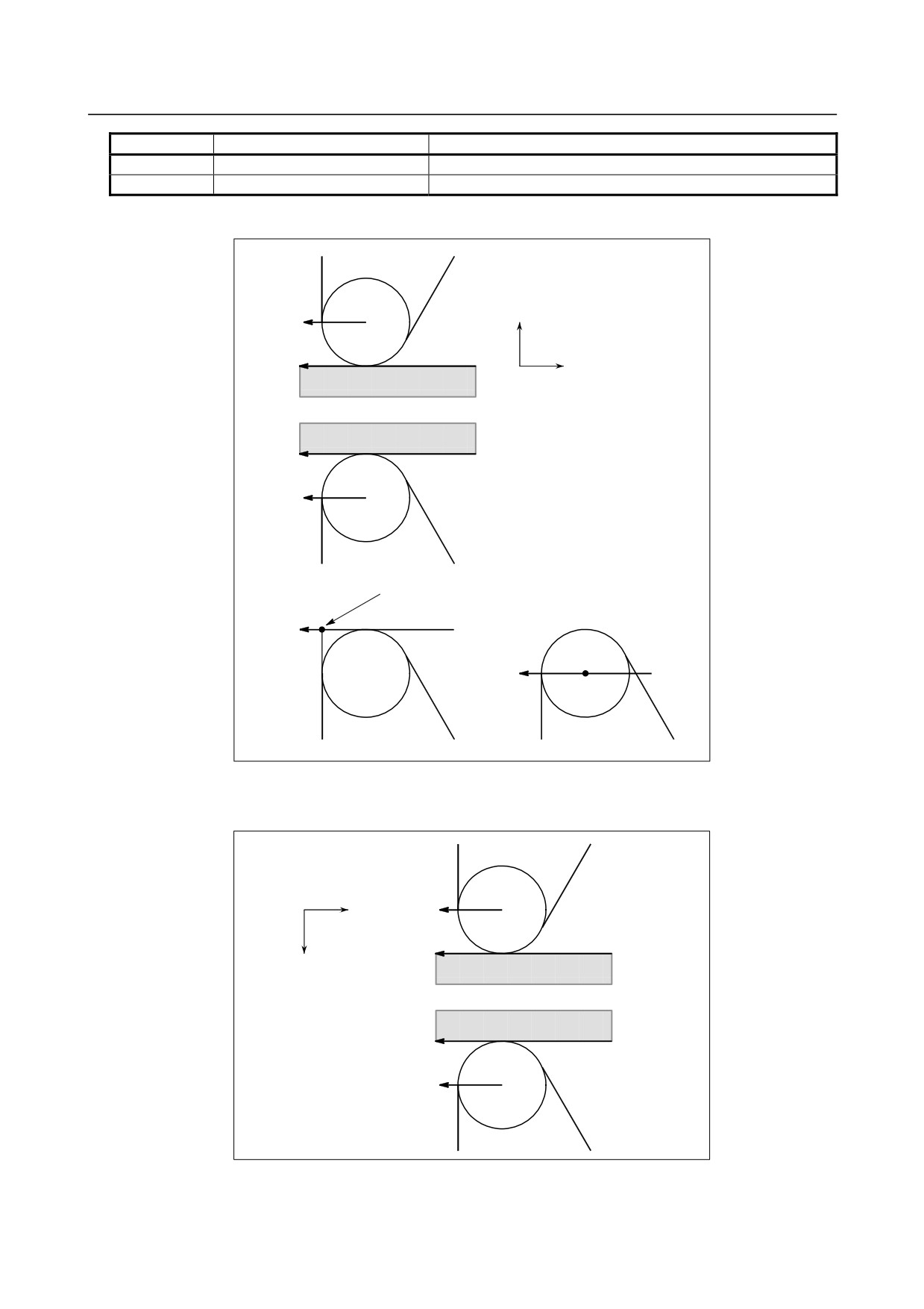
In tool nose radius compensation, the position of the workpiece with respect to the tool must be specified.
G code
Workpiece position
Tool path
G40
(Cancel)
Moving along the programmed path
- 181 -
6.COMPENSATION FUNCTION
PROGRAMMING
B-64484EN-2/02
G code
Workpiece position
Tool path
G41
Right side
Moving on the left side the programmed path
G42
Left side
Moving on the right side the programmed path
The tool is offset to the opposite side of the workpiece.
X axis
G42
Z axis
Workpiece
G41
The imaginary tool nose is on the
programmed path.
G40
G40
Imaginary tool nose
Imaginary tool nose
number 1 to 8
number 0
Fig. 6.5.4 (a) Workpiece position
The workpiece position can be changed by setting the coordinate system as shown below.
Z axis
G41 (the workpiece is on
the left side)
X axis
Workpiece
G42 (the workpiece is on
NOTE
the right side)
If the tool nose radius
compensation value is negative,
the workpiece position is changed.
Fig. 6.5.4 (b) When the workpiece position is changed
G40, G41, and, G42 are modal.
- 182 -
B-64484EN-2/02
PROGRAMMING
6.COMPENSATION FUNCTION
Don't specify G41 while in the G41 mode. If you do, compensation will not work properly.
Don't specify G42 while in the G42 mode for the same reason.
G41 or G42 mode blocks in which G41 or G42 are not specified are expressed by (G41) or (G42)
respectively.
CAUTION
If the sign of the compensation value is changed from plus to minus and vice
versa, the offset vector of tool nose radius compensation is reversed, but the
direction of the imaginary tool nose does not change. For a use in which the
imaginary tool nose is adjusted to the starting point, therefore, do not change the
sign of the compensation value for the assumed program.
Explanation
-
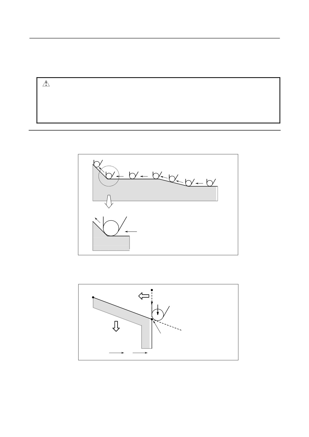
Tool movement when the workpiece position does not change
When the tool is moving, the tool nose maintains contact with the workpiece.
(G42)
(G42)
(G42)
(G42)
(G42)
(G42)
Enlarged
diagram
Fig. 6.5.4 (c) Tool movement when the workpiece position does not change
-
Tool movement when the workpiece position changes
The workpiece position against the tool changes at the corner of the programmed path as shown in the
following figure.
A
C
Workpiece
G41
position
G42
Workpiece
B
position
A
B
C
G41
G42
Fig. 6.5.4 (d) Tool movement when the workpiece position changes
Although the workpiece does not exist on the right side of the programmed path in the above case, the
existence of the workpiece is assumed in the movement from A to B. The workpiece position must not be
changed in the block next to the start-up block. In the example in the Fig. 6.5.4 (b), if the block specifying
motion from A to B were the start-up block, the tool path would not be the same as the one shown.
- 183 -
6.COMPENSATION FUNCTION
PROGRAMMING
B-64484EN-2/02
-
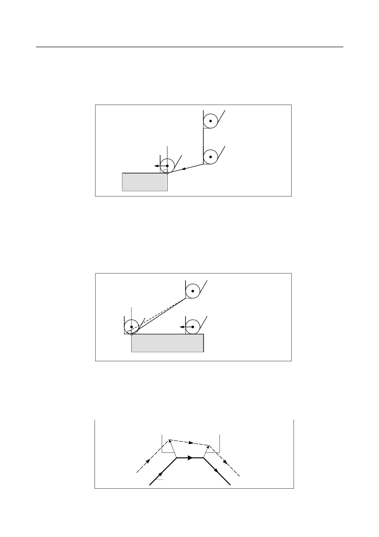
Start-up
The block in which the mode changes to G41 or G42 from G40 is called the start-up block.
G40 _ ;
G41 _ ; (Start-up block)
Transient tool movements for offset are performed in the start-up block. In the block after the start-up
block, the tool nose center is positioned vertically to the programmed path of that block at the start point.
G40
(G42)
G42 (Start-up)
Fig. 6.5.4 (e) Start-up
-
Offset cancel
The block in which the mode changes to G40 from G41 or G42 is called the offset cancel block.
G41 _ ;
G40 _ ; (Offset cancel block)
The tool nose center moves to a position vertical to the programmed path in the block before the cancel
block.
The tool is positioned at the end point in the offset cancel block (G40) as shown below.
End position
G40
(G42)
Fig. 6.5.4 (f) Offset cancel
-
Changing the compensation value
In general, the compensation value is to be changed when the tool is changed in offset cancel mode. If the
compensation value is changed in offset mode, however, the vector at the end point of the block is
calculated using the compensation value specified in that same block.
The same applies if the imaginary tool nose direction and the tool offset value are changed.
Calculated from the compensation
Calculated from the compensation
value specified in block N6.
value specified in block N7.
N7
N6
N8
Programmed path
Fig. 6.5.4 (g) Changing the compensation value
- 184 -
B-64484EN-2/02
PROGRAMMING
6.COMPENSATION FUNCTION
-
Specification of G41/G42 in G41/G42 mode
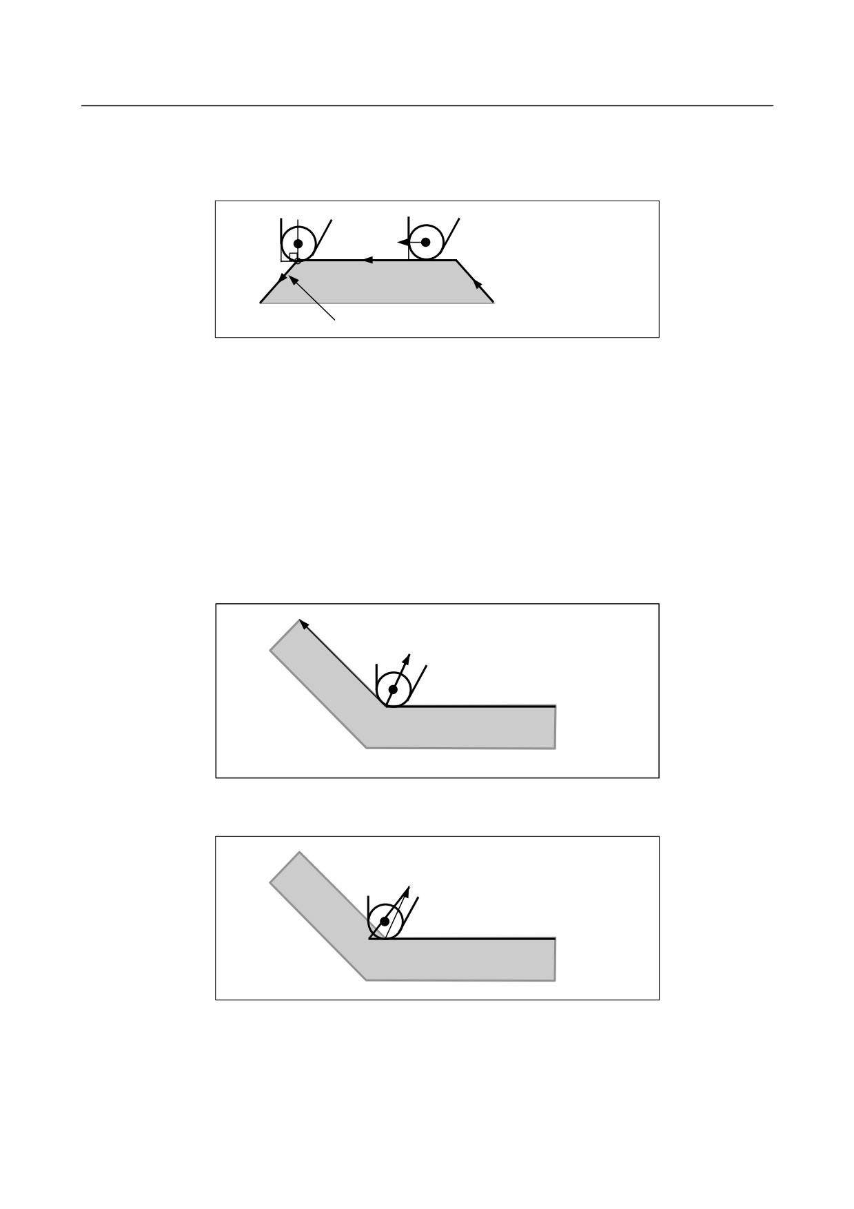
When a G41 or G42 code is specified again in G41/G42 mode, the tool nose center is positioned vertical
to the programmed path of the preceding block at the end point of the preceding block.
(G42)
(G42)
G42
(G18) G42 G91 Z-500.0 X-500.0 ;
Fig. 6.5.4 (h) Specification of G41/G42 in G41/G42 mode
In the block that first changes from G40 to G41/G42, the above positioning of the tool nose center is not
performed.
-
Tool movement when the moving direction of the tool in a block which
includes a G40 (offset cancel) command is different from the direction of the
workpiece
When you wish to retract the tool in the direction specified by X and Z canceling the tool nose radius
compensation at the end of machining the first block in Fig. 6.5.4 (i), specify the following :
G40 X _ Z _ I _ K _ ;
where I and K are the direction of the workpiece in the next block, which is specified in incremental
mode.
I,K
X,Z
Actual move command
G40
(G42)
G40 X_ Z_ I_ K_ ;
Fig. 6.5.4 (i) If I and K are specified in the same block as G40
Thus, this prevents the tool from overcutting, as shown in Fig. 6.5.4 (j).
X, Z
Actual move command
G40
(G42)
G40 X_ Z_ ;
Fig. 6.5.4 (j) Case in which overcutting occurs in the same block as G40
The workpiece position specified by addresses I and K is the same as that in the preceding block.
Specify I_K_; in the same block as G40. If it is specified in the same block as G02 or G03, it is assumed
to be the center of the arc.
- 185 -

6.COMPENSATION FUNCTION
PROGRAMMING
B-64484EN-2/02
G40 X_ Z_ I_ K_ ;
Tool nose radius compensation
G02 X_ Z_ I_ K_ ;
Circular interpolation
If I and/or K is specified with G40 in the cancel mode, the I and/or K is ignored. The numeral is followed
I and K should always be specified as radius values.
G40 G01 X_ Z_ ;
G40 G01 X_ Z_ I_ K_ ; Offset cancel mode (I and K are ineffective.)
Example
X
<3>
φ300
<1>
<2>
200
φ60
Z
120
0
30
150
(G40 mode)
<1> G42 G00 X60.0 ;
<2> G01 X120.0 Z-150.0 F10 ;
<3> G40 G00 X300.0 Z0 I40.0 K-30.0 ;
6.5.5
Notes on Tool Nose Radius Compensation
Explanation
-
Blocks without a move command that are specified in offset mode
<1> M05 ;
M code output
<2> S210 ;
S code output
<3> G04 X10.0 ;
Dwell
<4> G22 X100000 ;
Machining area setting
<5> G91 G01 X0 ;
Feed distance of zero
<6> G90 ;
G code only
<7> G10 L11 P01 R10.0 ;
Offset change
If the number of such blocks consecutively specified is more than N-2 blocks (where N is the number of
blocks to read in offset mode (parameter No. 19625)), the tool arrives at the position vertical to this block
at the end point of the previous block.
If the feed distance is 0 (<5>), this applies even if only one block is specified.
- 186 -
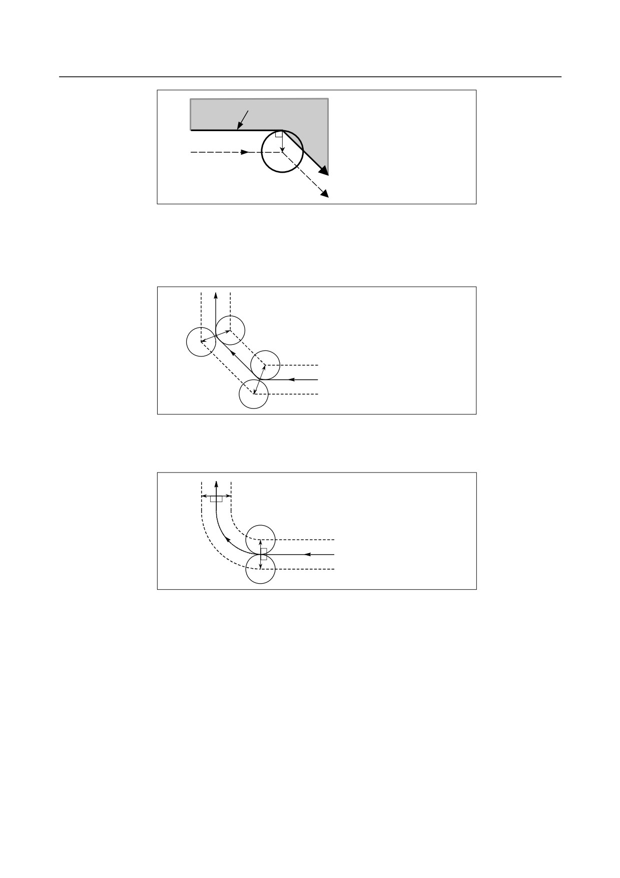
B-64484EN-2/02
PROGRAMMING
6.COMPENSATION FUNCTION
Programmed path
(G42 mode)
N6 G91 Z100.0 ;
N6
N7
N7 S21 ;
N8
N8 M04 ;
U9 X-100.0 Z100.0 ;
N9
(Number of blocks to be read
Tool nose center path
in offset mode = 3)
Fig. 6.5.5 (a)
Overcutting may, therefore, occur in the Fig. 6.5.5 (a).
-
Tool nose radius compensation when chamfering is performed
Movement after compensation is shown Fig. 6.5.5 (b).
(G42 mode)
G91 G01 Z-20.0, C10.0;
X20.0;
(G42)
Programmed path
(G41)
Fig. 6.5.5 (b)
-
Tool nose radius compensation when a corner R is performed
Movement after compensation is shown Fig. 6.5.5 (c).
(G42 mode)
G91 G01 Z-20.0, R10.0;
X20.0;
(G42)
Programmed path
(G41)
Fig. 6.5.5 (c)
- 187 -
6.COMPENSATION FUNCTION
PROGRAMMING
B-64484EN-2/02
6.6
DETAILS OF CUTTER OR TOOL NOSE RADIUS
COMPENSATION
6.6.1
Overview
The following explanation focuses on the cutter compensation, but applies to the tool nose radius
compensation as well.
-
Inner side and outer side
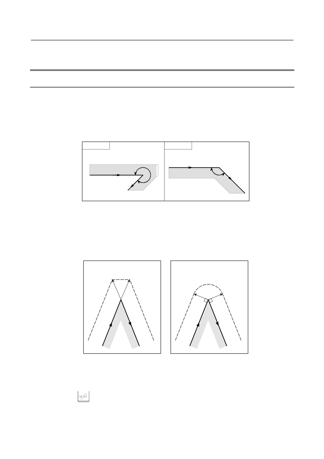
When an angle of intersection of the tool paths specified with move commands for two blocks on the
workpiece side is over 180°, it is referred to as "inner side." When the angle is between 0° and 180°, it is
referred to as "outer side."
Inner side
Outer side
Programmed path
Workpiece
α
α
Workpiece
Programmed path
180°≤a
0°≤α<180°
-
Outer corner connection method
If the tool moves around an outer corner in cutter compensation mode, it is possible to specify whether to
connect compensation vectors with linear interpolation or with circular interpolation, using bit 2 (CCC) of
parameter No. 19607.
<1> Linear connection type [Bit
<2> Circular connection type
2 (CCC) of parameter No.
[Bit 2 (CCC) of
19607 = 0]
parameter No. 19607 = 1]
Vectors are connected with linear
Vectors are connected with circular
interpolation.
interpolation.
-
Cancel mode
The cutter compensation enters the cancel mode under the following conditions. (The system may not
enter the cancel mode depending on the machine tool.)
<1> Immediately after the power is turned on
<2> When the
key on the MDI panel is pushed
<3> After a program is forced to end by executing M02 or M30
<4> After the cutter compensation cancel command (G40) is exercised
- 188 -
B-64484EN-2/02
PROGRAMMING
6.COMPENSATION FUNCTION
In the cancel mode, the compensation vector is set to zero, and the path of the center of tool coincides
with the programmed path. A program must end in cancel mode. If it ends in the cutter compensation
mode, the tool cannot be positioned at the end point, and the tool stops at a location the compensation
vector length away from the end point.
NOTE
The operation to be performed when a reset operation is performed during cutter
compensation differs depending on bit 6 (CLR) of parameter No. 3402.
- If CLR is 0
The system enters the reset state. G41/G42 are retained as the modal code
of group 07, but to perform cutter compensation, an offset number (D code)
must be specified again.
- If CLR is 1
The system enters the clear state. The modal code of group 07 is G40, and to
perform cutter compensation again, G41/G42 and an offset number (D code)
must be specified.
-
Start-up
When a block which satisfies all the following conditions is executed in cancel mode, the CNC enters the
cutter compensation mode. Control during this operation is called start-up.
<1> G41 or G42 is contained in the block, or has been specified to place the CNC in the cutter
compensation mode.
<2> 0 < compensation number of cutter compensation ≤ maximum compensation number
<3> Positioning (G00) or linear interpolation (G01) mode
<4> A compensation plane axis command with a travel distance of 0 (except start-up type C) is specified.
If start-up is specified in circular interpolation (G02, G03) mode, PS0034 will occur.
In a start-up block, workpiece coordinate system switching (G54 to G59) cannot be specified.
As a start-up operation, one of the three types A, B, and C can be selected by setting bit 0 (SUP) of
parameter No. 5003 and bit 1 (SUV) of parameter No. 5003 appropriately. The operation to be performed
if the tool moves around an inner side is of single type only.
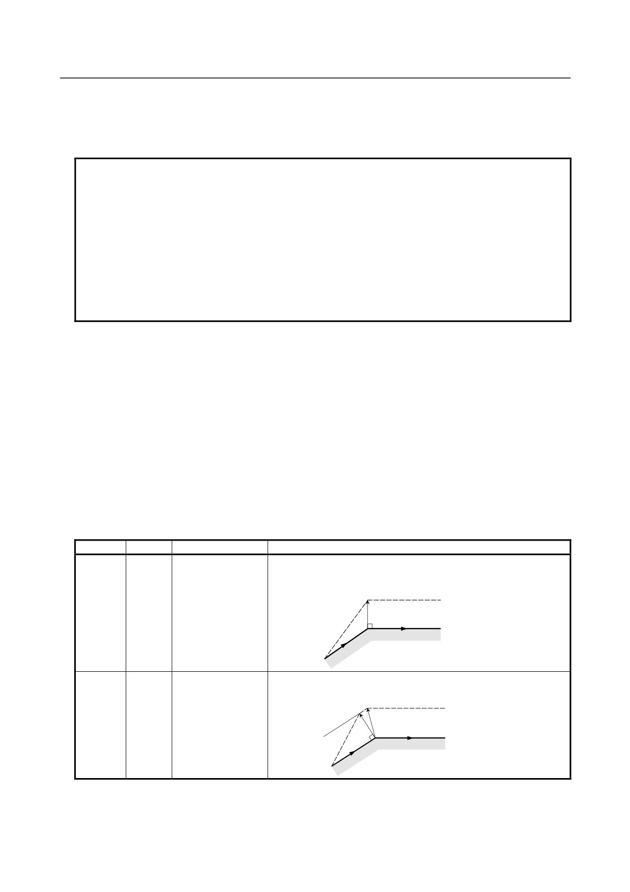
Table 6.6.1 (a) Start-up/cancel operation
SUV
SUP
Type
Operation
0
0
Type A
A compensation vector is output, which is vertical to the block
subsequent to the start-up block and the block preceding the cancel
block.
Tool center path
G41
Programmed path
N2
N1
0
1
Type B
A compensation vector is output, which is vertical to the start-up
block and the cancel block. An intersection vector is also output.
Intersection
Tool center path
Programmed path
G41
N2
N1
- 189 -
6.COMPENSATION FUNCTION
PROGRAMMING
B-64484EN-2/02
SUV
SUP
Type
Operation
1
0
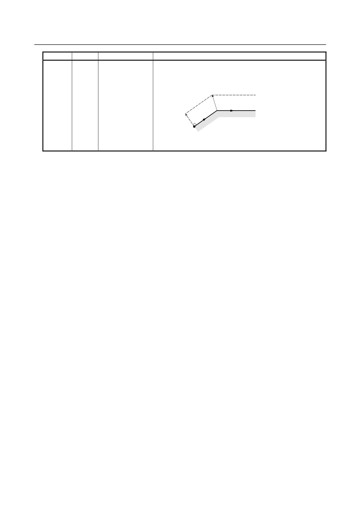
Type C
When the start-up block and the cancel block are blocks without tool
1
movement, the tool moves by the tool radius ⋅ tool nose radius
compensation value in the direction vertical to the block subsequent
to the start-up block and the block preceding the cancel block.
Intersection
Tool center path
Programmed path
Programmed
N3
path
G41
N2
N1
For a block with tool movement, the tool follows the SUP setting: If it
is 0, type A is assumed and if 1, type B is assumed.
-
Reading input commands in cutter compensation mode
In cutter compensation mode, input commands are read from usually three blocks and up to eight blocks
depending on the setting of parameter No. 19625 to perform intersection calculation or an interference
check, described later, regardless of whether the blocks are with or without tool movement, until a cancel
command is received.
To perform intersection calculation, it is necessary to read at least two blocks with tool movement. To
perform an interference check, it is necessary to read at least three blocks with tool movement.
As the setting of parameter No. 19625, that is, the number of blocks to read, increases, it is possible to
predict overcutting (interference) for up to more subsequent commands. Increases in blocks to read and
analyze, however, cause reading and analysis to take more time.
-
Ending (canceling) cutter compensation
In cutter compensation mode, cutter compensation is canceled if a block that satisfies at least either one of
the following conditions is executed:
<1> G40 is specified.
<2> D00 is specified as the compensation number of cutter compensation.
If cutter compensation cancel is to be performed, it must not be by a circular command (G02, G03).
Otherwise, an alarm will occur.
For a cancel operation, one of three types, A, B, and C, can be selected by appropriately setting bit 0
(SUP) of parameter No. 5003 and bit 1 (SUV) of parameter No. 5003. The operation to be performed if
the tool turns around the inside is of a single type.
- 190 -
B-64484EN-2/02
PROGRAMMING
6.COMPENSATION FUNCTION
-
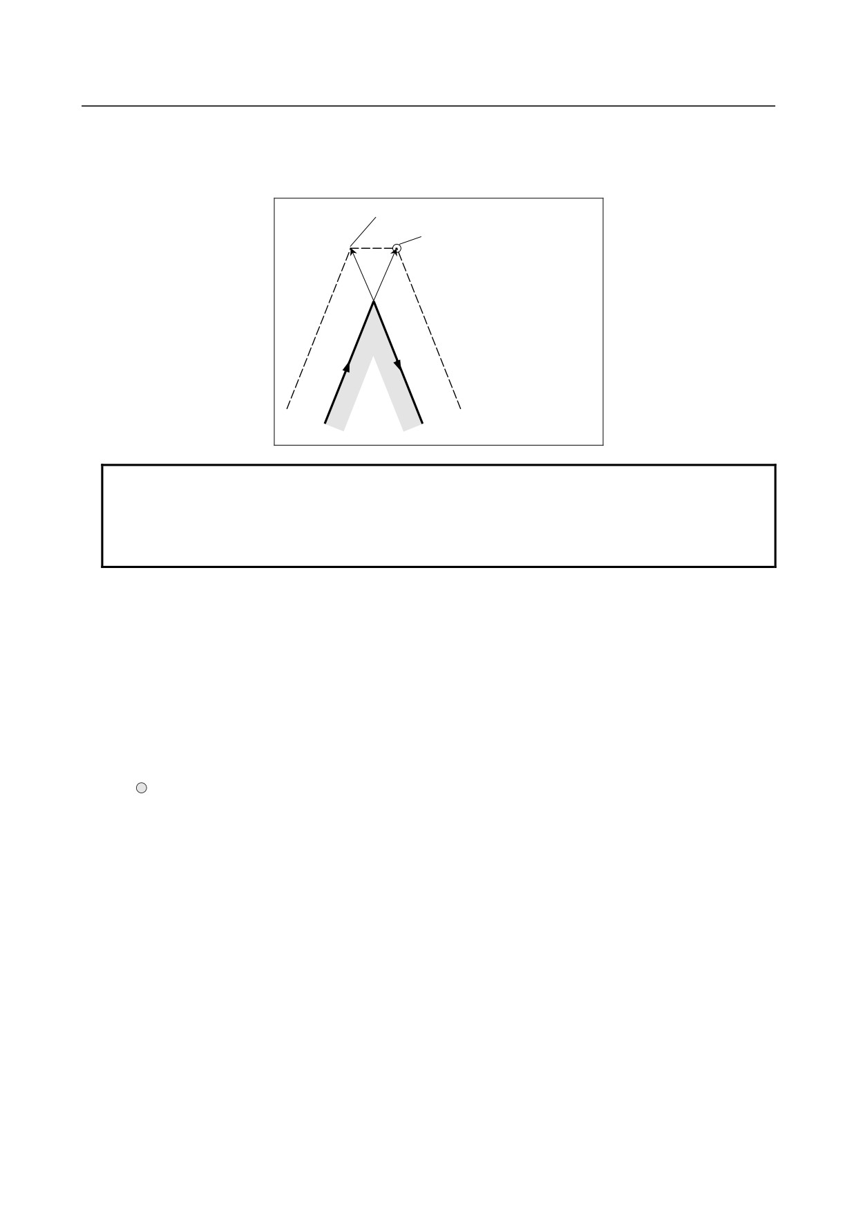
Bit 0 (SBK) of parameter No. 5000
When bit 0 (SBK) of parameter No. 5000 is set to 1, a single block stop can be performed in a block
created internally for cutter compensation.
Use this parameter to check a program including cutter compensation.
Stop point in a block created internally
Single block stop point
N1
S
N1
N2
N2
N1
Cutter center path
Programmed path
NOTE
When an auxiliary function (M code), spindle speed function (S code), tool
function (T code), or second auxiliary function (B code) is specified in the N1
block in the figure above, FIN is not accepted if the tool stops at the stop point in
a block created internally (excluding the single block stop point).
-
Meaning of symbols
The following symbols are used in subsequent figures:
• S indicates a position at which a single block is executed once.
• SS indicates a position at which a single block is executed twice.
• SSS indicates a position at which a single block is executed three times.
• L indicates that the tool moves along a straight line.
• C indicates that the tool moves along an arc.
• r indicates the tool radius ⋅ tool nose radius compensation value.
• An intersection is a position at which the programmed paths of two blocks intersect with each other
after they are shifted by r.
•
indicates the center of the tool.
- 191 -
6.COMPENSATION FUNCTION
PROGRAMMING
B-64484EN-2/02
6.6.2
Tool Movement in Start-up
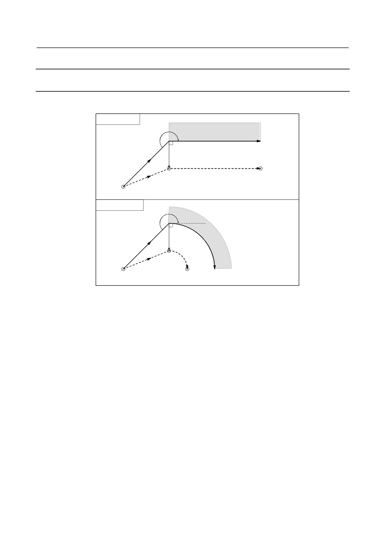
When the offset cancel mode is changed to offset mode, the tool moves as illustrated below (start-up):
Explanation
-
Tool movement around an inner side of a corner (180°≤ α)
Linear→Linear
α
Workpiece
Programmed path
r
G42
S
L
Tool center path
L
Start point
Linear→Circular
α
Work-
G42
piece
S
C
L
Start point
Tool center path Programmed path
- 192 -
B-64484EN-2/02
PROGRAMMING
6.COMPENSATION FUNCTION
-
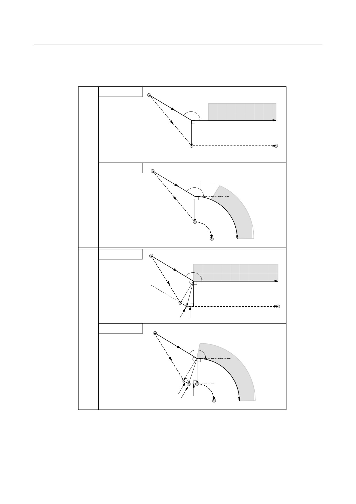
Cases in which the start-up block is a block with tool movement and the tool
moves around the outside at an obtuse angle (90°≤ α<180°)
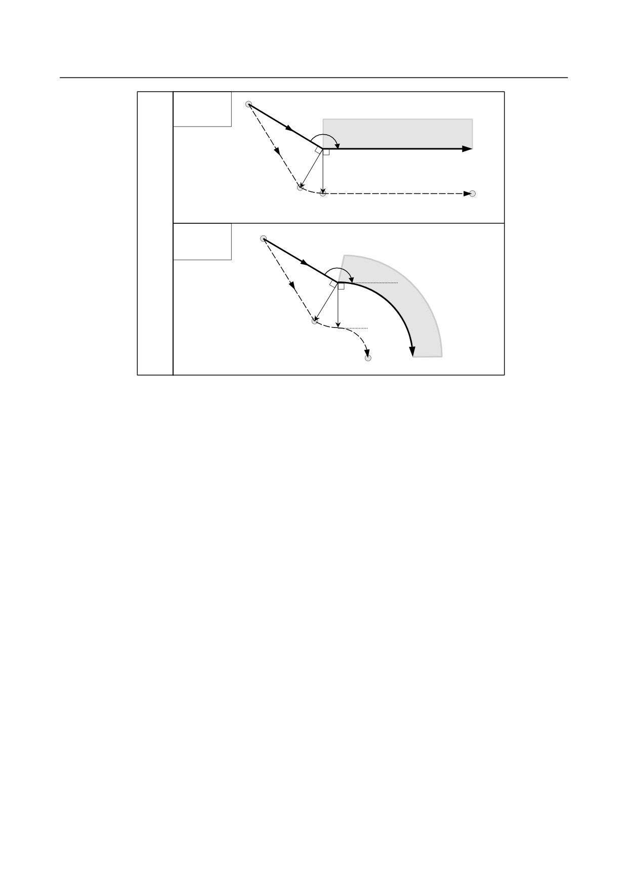
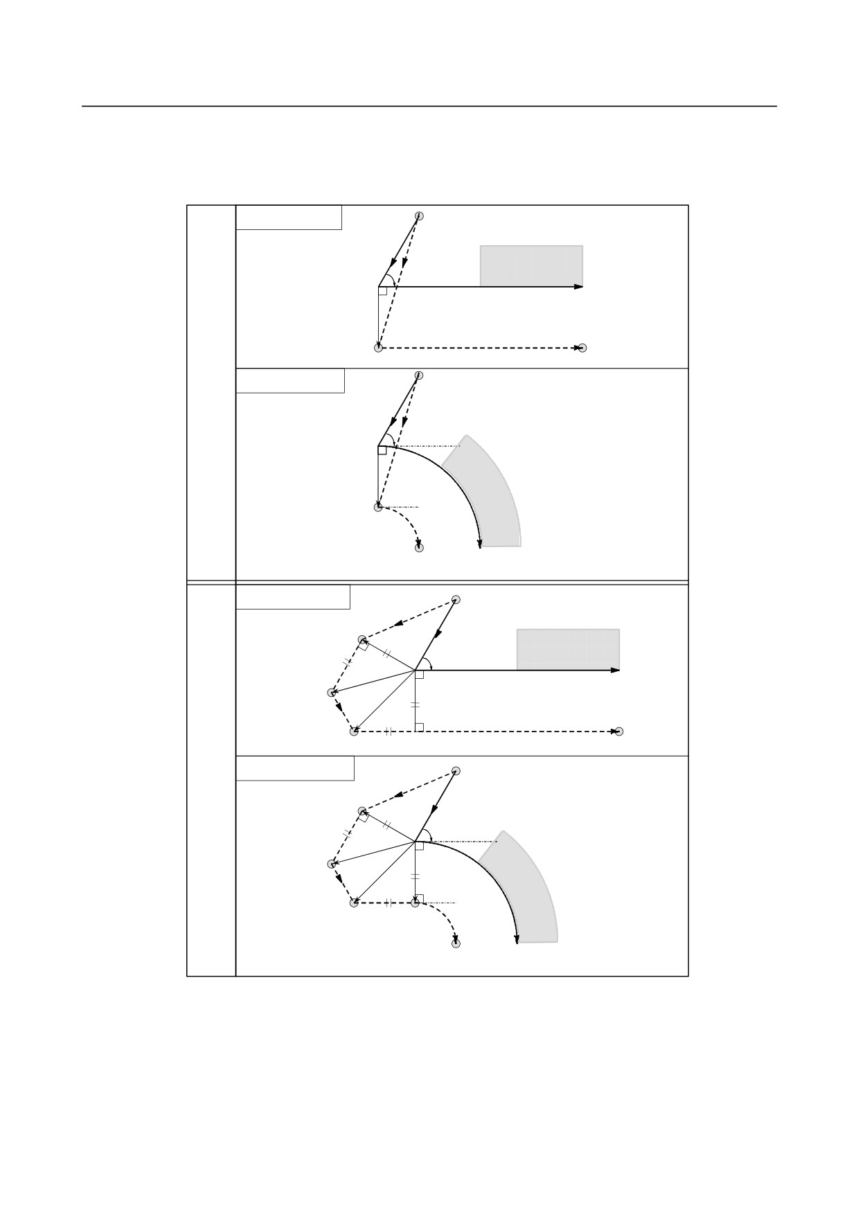
Tool path in start-up has two types A and B, and they are selected by bit 0 (SUP) of parameter No. 5003.
Linear→Linear
Start point
G42
α
Workpiece
L
Programmed path
r
S
L
Tool center path
Type
A
Linear→Circular
Start point
G42
α
L
r
Work-
piece
S
C
Tool center path
Programmed path
Linear→Linear
(Linear connection type)
Start point
G42
α
Workpiece
L
Programmed path
r
r
L
S
Tool center path
Intersection
L
Type
Linear→Circular
B
Start point
(Linear connection type)
G42
α
L
r
Work-
r
piece
S
C
L
L
Intersection
Tool center path
Programmed path
- 193 -
6.COMPENSATION FUNCTION
PROGRAMMING
B-64484EN-2/02
Linear→Linear
Start point
(Circular
connection type)
G42
α
Workpiece
L
Programmed path
r
r
C
L
S
Tool center path
Type
B
Linear→Circular
Start point
(Circular
connection type)
G42
α
L
r
Workpiece
r
C
S
C
Tool center path Programmed path
- 194 -
B-64484EN-2/02
PROGRAMMING
6.COMPENSATION FUNCTION
-
Cases in which the start-up block is a block with tool movement and the tool
moves around the outside at an acute angle (α<90°)
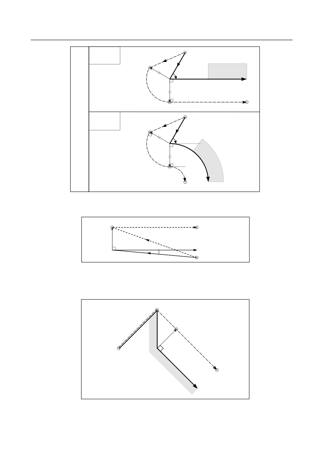
Tool path in start-up has two types A and B, and they are selected by bit 0 (SUP) of parameter No. 5003.
Linear→Linear
Start point
G42
Workpiece
α L
Programmed path
r
S
L
Tool center path
Type
A
Linear→Circular
Start point
G42
L
α
r
Work-
piece
S
C
Tool center path
Programmed path
Linear→Linear
Start point
(Linear connection type)
L
G42
Workpiece
r
α
L
Programmed path
r
L
S
L
L
Tool center path
Type
Linear→Circular
B
Start point
(Linear connection type)
L
G42
r
α
L
r
L
Work-
S
L
C
piece
Tool center path
Programmed path
- 195 -
6.COMPENSATION FUNCTION
PROGRAMMING
B-64484EN-2/02
Linear→Linear
Start point
(Circular
L
connection type)
G42
Workpiece
r
α
Programmed path
r
C
S
L
Tool center path
Type
B
Linear→Circular
Start point
(Circular
L
connection type)
G42
r
α
r
Work-
C
piece
S
C
Tool center path
Programmed path
-
Tool movement around the outside linear → linear at an acute angle less than
1 degree (α<1°)
S
Tool center path
L
r
L
Programmed path
(G41)
G41
Start point
Less than 1 deg
-
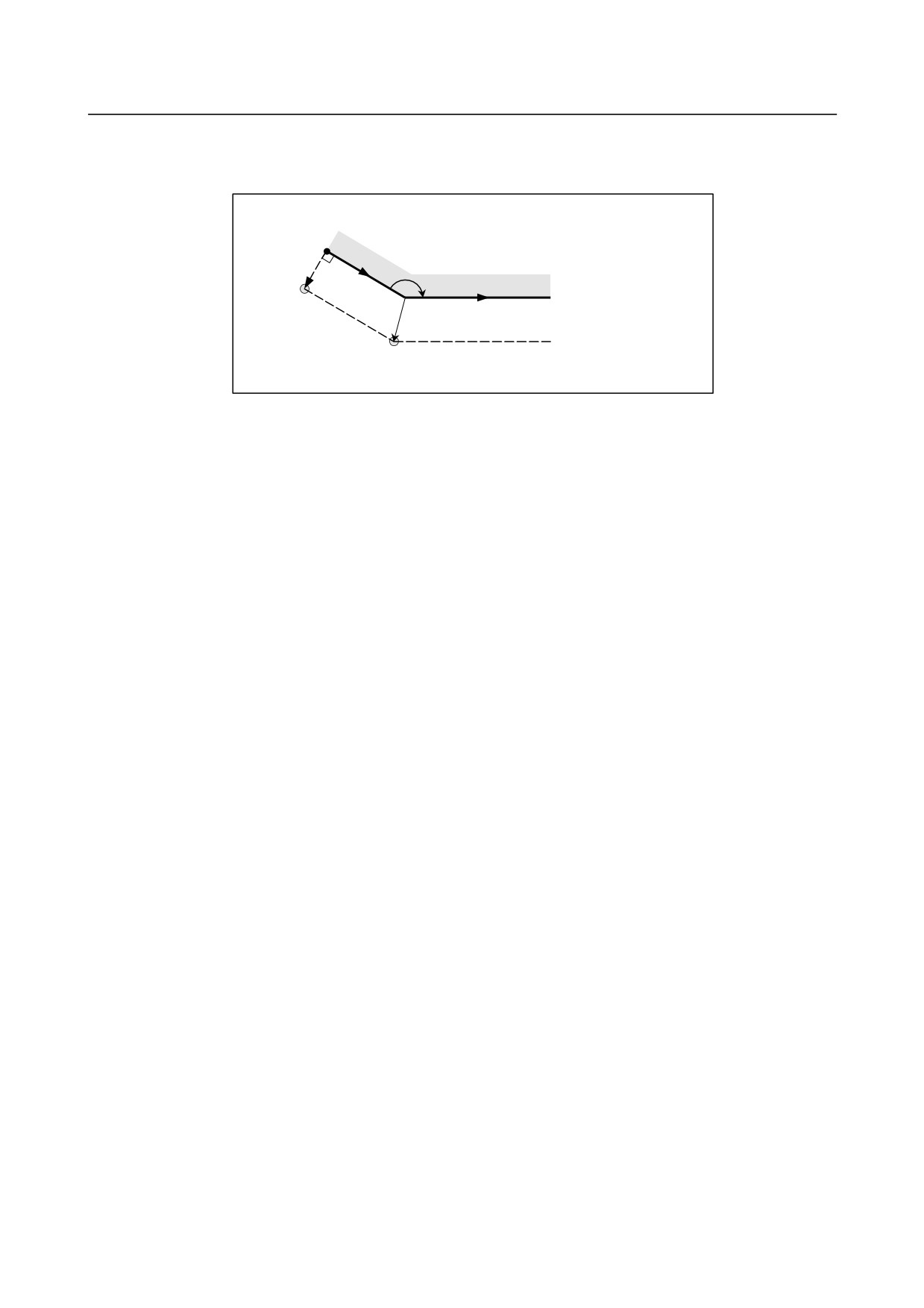
A block without tool movement specified at start-up
For type A and B
If the command is specified at start-up, the offset vector is not created. The tool does not operate in a
start-up block.
SS
N7
S
N6
N8
r
Tool center path
G40 … ;
N9
N6 X100.0 Y100.0 ;
N7 G41 X0 ;
N8 Y-100.0 ;
N9 Y-100.0 X100.0 ;
Programmed path
- 196 -
B-64484EN-2/02
PROGRAMMING
6.COMPENSATION FUNCTION
For type C
The tool shifts by the compensation value in the direction vertical to the block with tool movement
subsequent to the start-up block.
Without tool
movement
L
α
S
Programmed path
L
Tool center path
S
Intersection
- 197 -
6.COMPENSATION FUNCTION
PROGRAMMING
B-64484EN-2/02
6.6.3
Tool Movement in Offset Mode
In offset mode, compensation is performed even for positioning commands, not to speak of linear and
circular interpolations. To perform intersection calculation, it is necessary to read at least two blocks with
tool movement. If, therefore, two or more blocks with tool movement cannot be read in offset mode
because blocks without tool movement, such as auxiliary function independent commands and dwell, are
specified in succession, excessive or insufficient cutting may occur because intersection calculation fails.
Assuming the number of blocks to read in offset mode, which is determined by parameter No. 19625, to
be N and the number of commands in those N blocks without tool movement that have been read to be M,
the condition under which intersection calculation is possible is (N - 2) ≥ M. For example, if the
maximum number of blocks to read in offset mode is 5, intersection calculation is possible even if up to
three blocks without tool movement are specified.
NOTE
The condition necessary for an interference check, described later, differs from
this condition. For details, see the explanation of the interference check.
If a G or M code in which buffering is suppressed is specified, no subsequent commands can be read
before that block is executed, regardless of the setting of parameter No. 19625. Excessive or insufficient
cutting may, therefore, occur because of an intersection calculation failure.
- 198 -
B-64484EN-2/02
PROGRAMMING
6.COMPENSATION FUNCTION
-
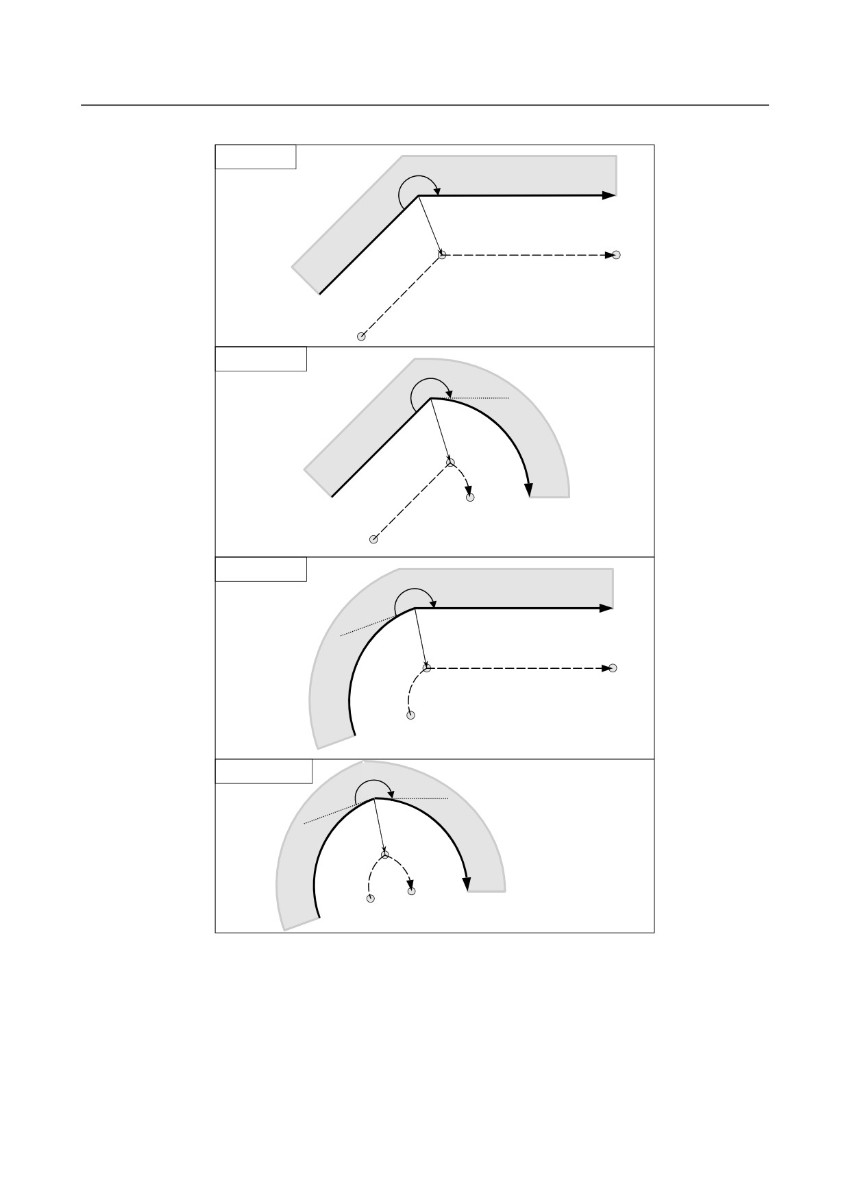
Tool movement around the inside of a corner (180°≤ α)
Linear→Linear
α
Workpiece
Programmed path
S
L
Tool center path
Intersection
L
Linear→Circular
α
Work-
piece
Intersection
S
C
L
Tool center path
Programmed path
Circular→Linear
α
Workpiece
Programmed path
L
S
Tool center path
C Intersection
Circular→Circular
α
Work-
Intersection
piece
S
C
C
Tool center
Programmed path
path
- 199 -
6.COMPENSATION FUNCTION
PROGRAMMING
B-64484EN-2/02
-
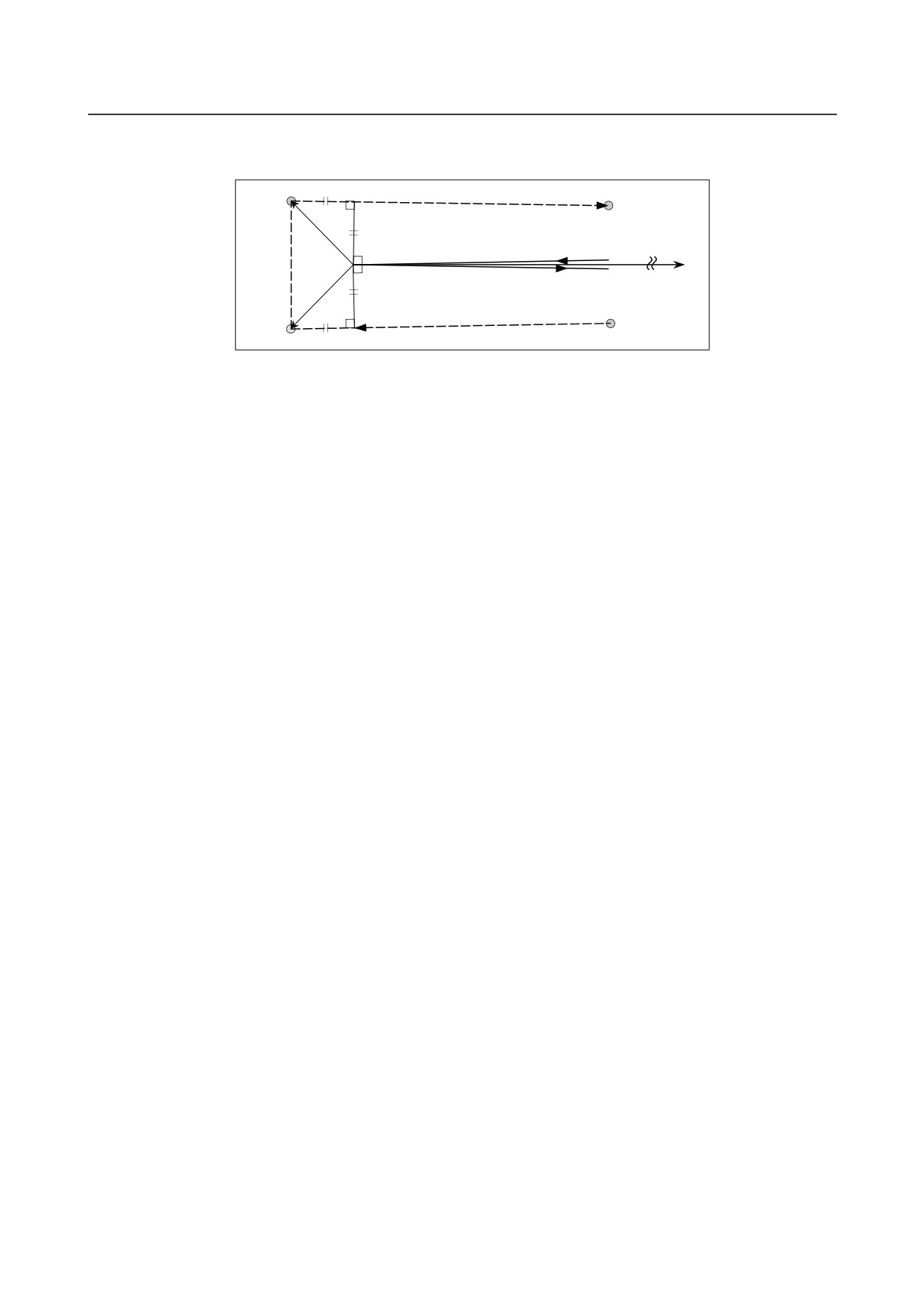
Tool movement around the inside (α<1°) with an abnormally long vector,
linear → linear
Intersection
r
Tool center path
Programmed path
r
r
S
Intersection
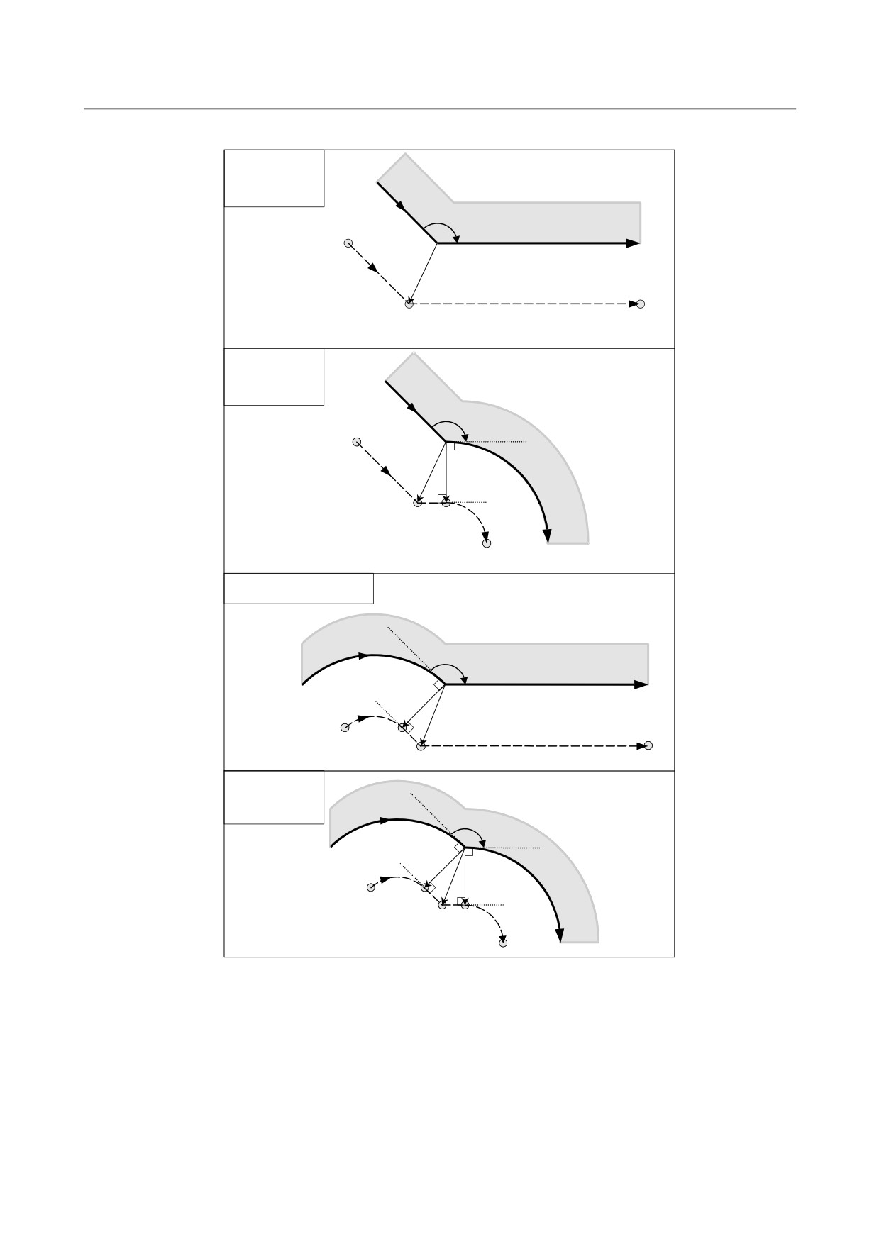
Also in case of arc to straight line, straight line to arc and arc to arc, the reader should infer in the same
procedure.
- 200 -
B-64484EN-2/02
PROGRAMMING
6.COMPENSATION FUNCTION
-
Tool movement around the outside corner at an obtuse angle (90°≤α<180°)
Linear→Linear
(Linear
connection type)
α
Workpiece
L
Programmed path
S
Intersection
L
Tool center path
Linear→Circular
(Linear
connection type)
α
Work-
L
r
piece
S L
C
Intersection
Tool center path Programmed path
Circular→Linear
(Linear connection type)
α
Workpiece
Programmed path
r
C
L
Intersection S
L
Tool center path
6
Circular→Circular
(Linear
connection type)
α
Programmed path
r
Work-
r
piece
C
Tool center
L
path
S
L
Intersection
C
- 201 -