FANUC Series 30i-MODEL B, 31i-MODEL B, 32i-MODEL B. For Machining Center System. OPERATOR'S MANUAL - page 9
6.COMPENSATION FUNCTION
PROGRAMMING
B-64484EN-2/02
Post-compensation path
Re-calculation
Programmed path
Block 1
Block 8
Block 1
Block 8
Post-compensati
Post-compensation
on intersection
Post-compensation
vector between
intersection vector
intersection between
block 1 and
between block 1
gap vector and block 8
block 8
and gap vector
Block 2
Gap vector
Block 7
Block 2
Block 7
Block 3
Block 3
Block 6
Block 6
Block 4
Block 4
Block 5
Block 5
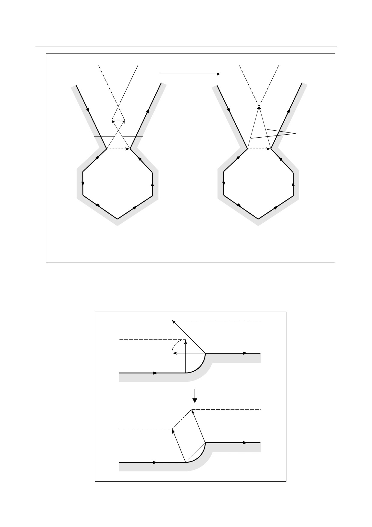
In this case, the post-compensation end points of blocks 2 to 7
coincide with the end point of block 1. Thus, after compensation,
blocks 2 to 7 will be blocks without tool movement.
Fig. 6.6.6.3 (b)
If the tool radius/tool nose radius compensation value is greater than the radius of the specified arc as
shown in the Fig. 6.6.6.3 (c), and a command is specified which results in compensation with respect to
the inside of the arc, interference is avoided by performing intersection calculation with an arc command
being assumed a linear one. In this case, avoided vectors are connected with linear interpolation.
Post-compensation path
Programmed path
Fig. 6.6.6.3 (c)
- 232 -
B-64484EN-2/02
PROGRAMMING
6.COMPENSATION FUNCTION
-
If no interference avoidance vector exists
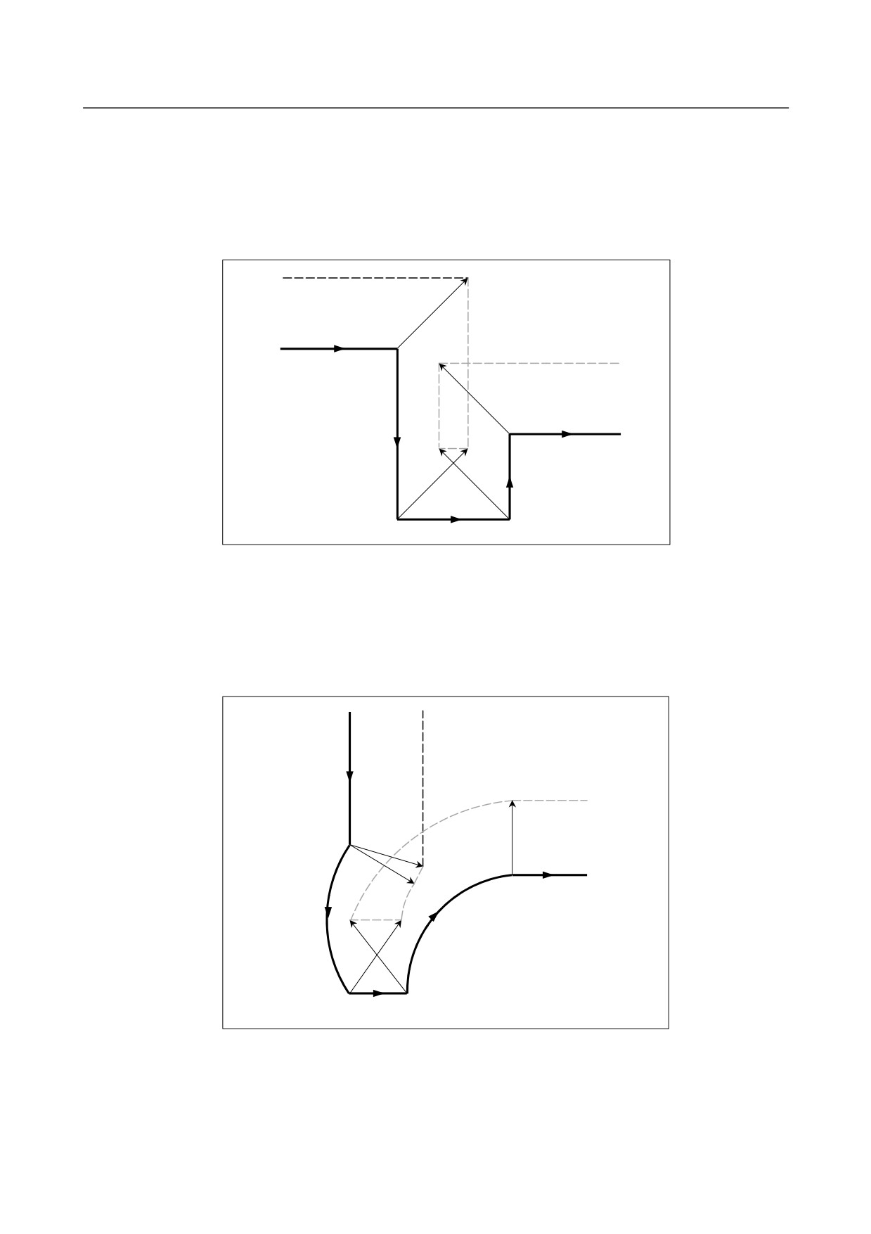
If the parallel pocket shown in the Fig. 6.6.6.3 (d) is to be machined, the end-point vector of block 1 and
the end-point vector of block 2 are judged to interfere, and an attempt is made to calculate, as an
interference avoidance vector, the intersection vector of the post-compensation path of block 1 and the
post-compensation path of block 3. In this case, because blocks 1 and 3 are parallel to each other, no
intersection exists. In this case, an alarm will occur immediately before block 1 and the tool will stop.
Stopped
Tool center path
Programmed path
Block 1
Block 3
Block 2
Fig. 6.6.6.3 (d)
If the circular pocket shown in the Fig. 6.6.6.3 (e) is to be machined, the end-point vector of block 1 and
the end-point vector of block 2 are judged to interfere, and an attempt is made to calculate, as an
interference avoidance vector, the intersection vector of the post-compensation path of block 1 and the
post-compensation path of block
3. In this case, because blocks
1 and
3 are circular, no
post-compensation intersection exists. In this case, an alarm will occur immediately before block 1 and
the tool will stop, as in the previous example.
Programmed path
Tool center path
Stopped
Block 1
Block 3
Block 2
Fig. 6.6.6.3 (e)
- 233 -
6.COMPENSATION FUNCTION
PROGRAMMING
B-64484EN-2/02
-
If it is judged dangerous to avoid interference
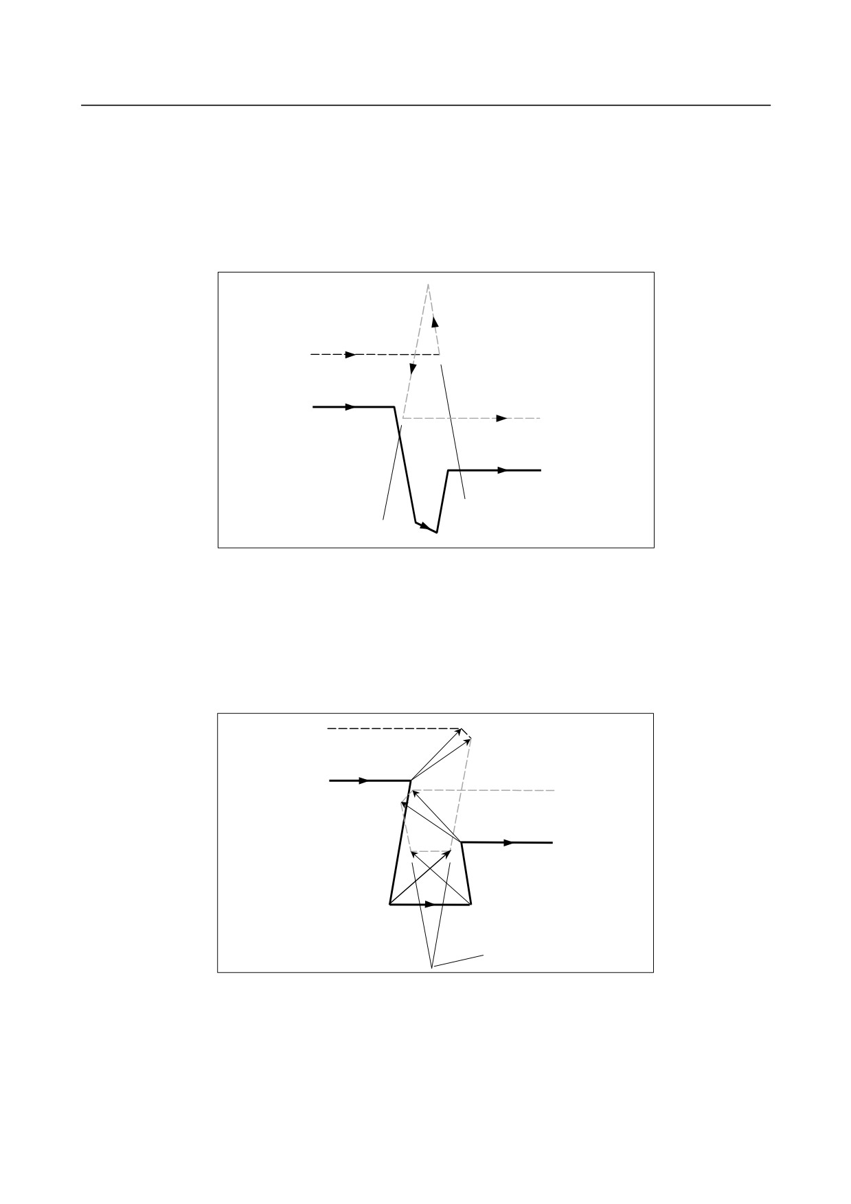
If the acute-angle pocket shown in the Fig. 6.6.6.3 (f) is to be machined, the end-point vector of block 1
and the end-point vector of block 2 are judged to interfere, and an attempt is made to calculate, as an
interference avoidance vector, the intersection vector of the post-compensation path of block 1 and the
post-compensation path of block 3. In this case, the movement direction of the post-avoidance path
extremely differs from the previously specified direction. If the post-avoidance path extremely differs
from that of the original command (90° or greater or 270° or less), interference avoidance operation is
judged dangerous; an alarm will occur immediately before block 1 and the tool will stop.
Post-compensation intersection of
blocks 1 and 3
Tool center path
Stopped
Programmed path
Block 1
Block 3
Block 2
Fig. 6.6.6.3 (f)
If a pocket in which the bottom is wider than the top, such as that shown in the Fig. 6.6.6.3 (g), is to be
machined, the end-point vector of block 1 and the end-point vector of block 2 are judged to interfere, and
an attempt is made to calculate, as an interference avoidance vector, the intersection vector of the
post-compensation path of block 1 and the post-compensation path of block 3. In this case, the relation
between blocks 1 and 3 is judged an outer one, the post-avoidance path results in overcutting as compared
with the original command. In such a case, interference avoidance operation is judge dangerous; an alarm
will occur immediately before block 1 and the tool will stop.
Stopped
Tool center path
Programmed path
Block 1
Block 3
Block 2
Post-compensation intersection
of blocks 1 and 3
Fig. 6.6.6.3 (g)
-
If further interference with an interference avoidance vector occurs
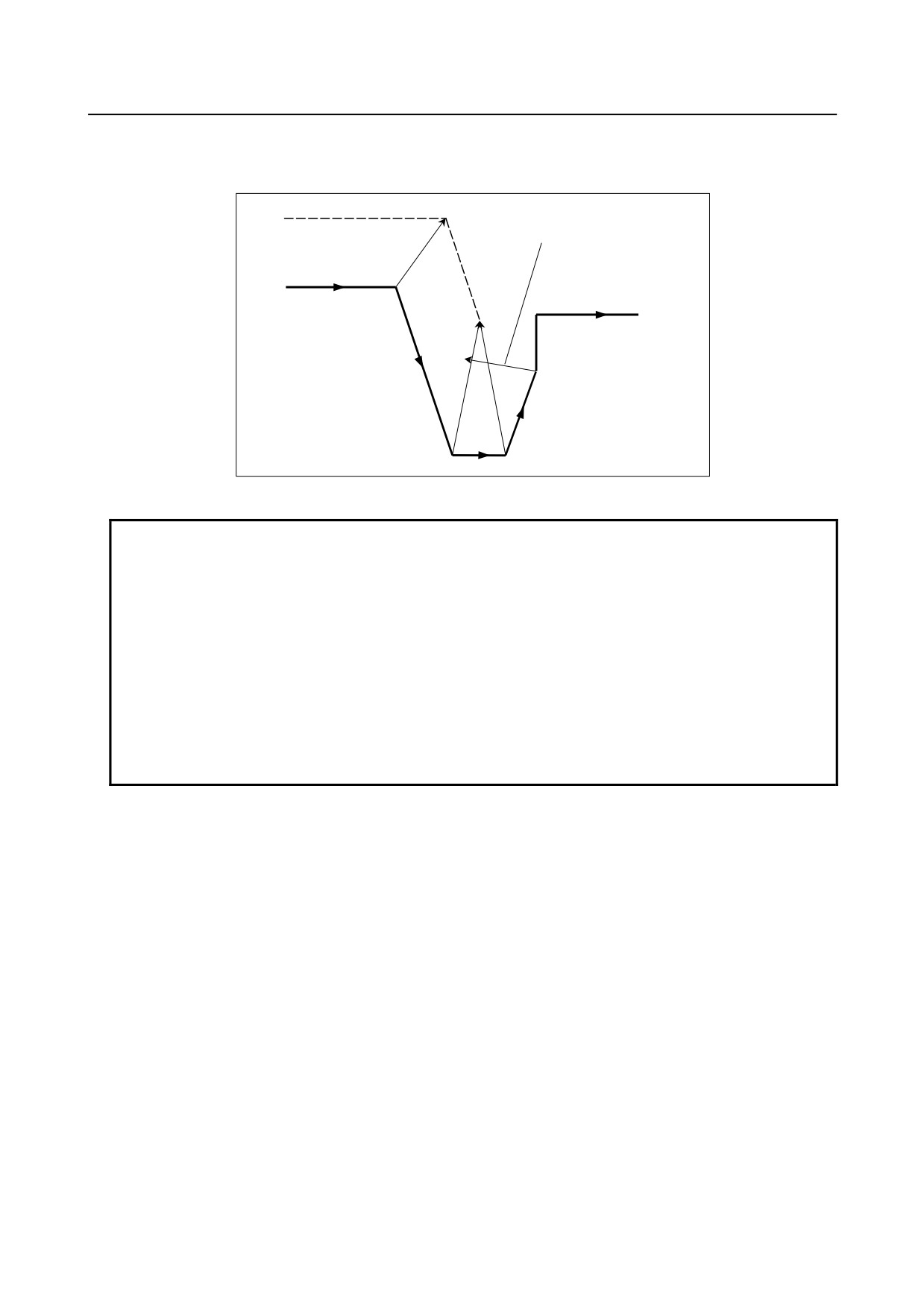
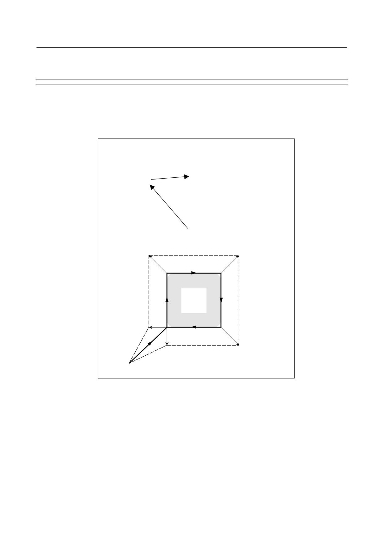
If the pocket shown in the Fig. 6.6.6.3 (h) is to be machined, if the number of blocks to read is 3, the
end-point vector of block 1 and the end-point vector of block 2 are judged to interfere, and an attempt is
made to calculate, as an interference avoidance vector, the intersection vector of the post-compensation
path of block 1 and the post-compensation path of block 3. In this case, however, the end-point vector of
block 3 that is to be calculated next further interferes with the previous interference avoidance vector.
- 234 -
B-64484EN-2/02
PROGRAMMING
6.COMPENSATION FUNCTION
If a further interference occurs to the interference avoidance vector once created and output, the
movement in the block will not be performed; an alarm will occur immediately before the block and the
tool will stop.
The intersection vectors of
blocks 3 and 4 further
Tool center path
interfere.
Programmed path
Sropped
Block 5
Block 4
Block 1
Block 3
Block 2
Fig. 6.6.6.3 (h)
NOTE
1 For "If it is judged dangerous to avoid interference" and "If further interference
with an interference avoidance vector occurs", by setting bit 6 (NAA) of
parameter No. 19607 appropriately, it is possible to suppress an alarm to
continue machining. For "If no interference avoidance vector exists", however, it
is not possible to avoid an alarm regardless of the setting of this parameter.
2 If a single block stop occurs during interference avoidance operation, and an
operation is performed which differs from the original movement, such as
manual intervention, MDI intervention, tool radius / tool nose radius
compensation value change, intersection calculation is performed with a new
path. If such an operation is performed, therefore, an interference may occur
again although interference avoidance has been performed once.
- 235 -
6.COMPENSATION FUNCTION
PROGRAMMING
B-64484EN-2/02
6.6.7
Tool Radius / Tool Nose Radius Compensation for Input from
MDI
Explanation
-
MDI operation
During MDI operation, that is, if a program command is specified in MDI mode in the reset state to make
a cycle start, intersection calculation is performed for compensation in the same way as in memory
operation/DNC operation. Compensation is performed in the same way if a subprogram is called from
program memory due to MDI operation.
Subprogram in program memory
MDI command
G90 G00 X0 Y0 ;
O9000 ;
M98 P9000 ;
N1 G41 G17 G91 G01 X10. Y10. D1 ;
M02 ;
N2 Y15. ;
N3 X15. ;
N4 Y-15. ;
N5 X-15. ;
N6 G40 X-10. Y-10. ;
M99 ;
N3
N2
N4
N1
N5
N6
-
MDI intervention
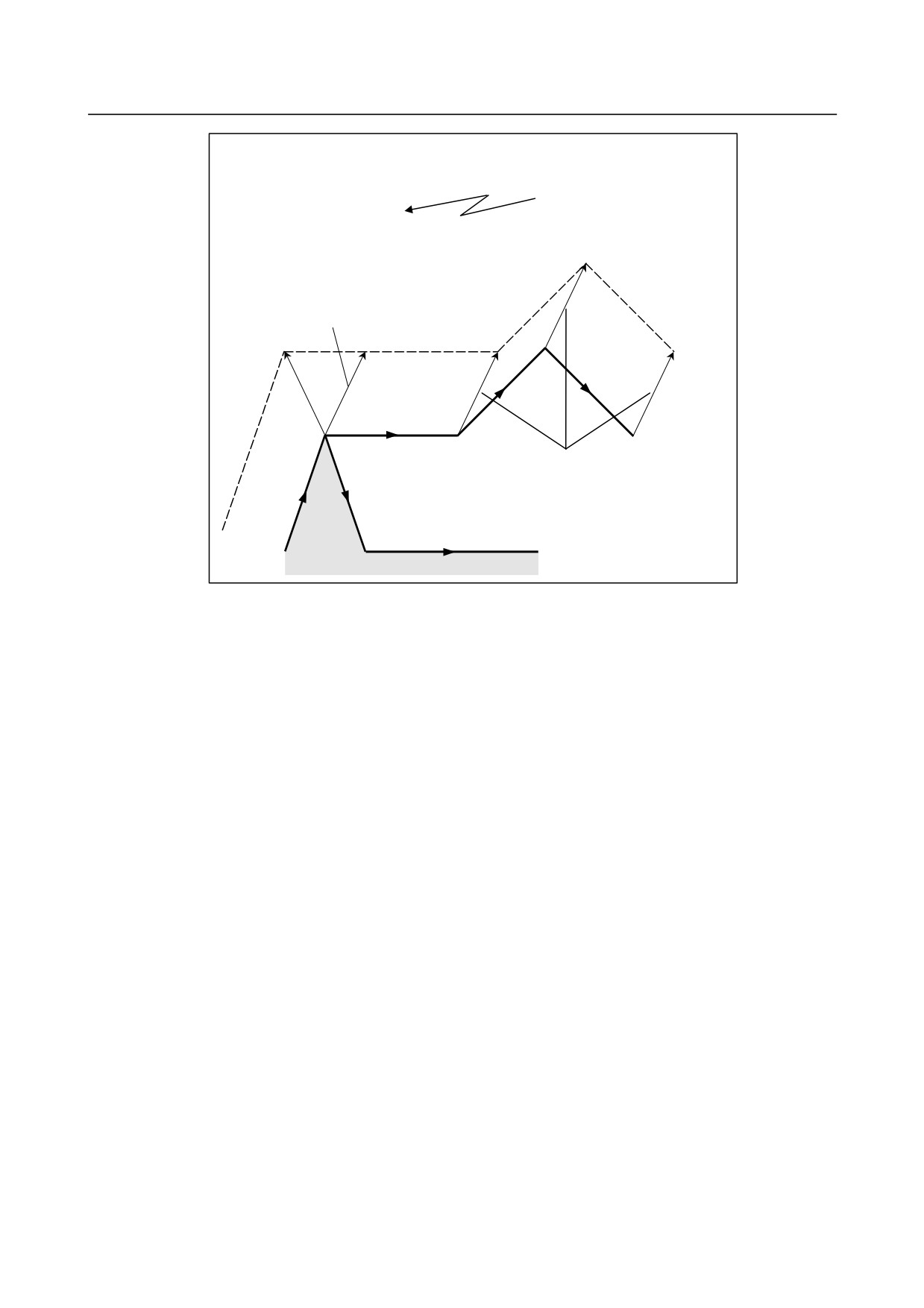
If MDI intervention is performed, that is, if a single block stop is performed to enter the automatic
operation stop state in the middle of memory operation, DNC operation, and the like, and a program
command is specified in MDI mode to make a cycle start, cutter compensation does not perform
intersection calculation, retaining the last compensation vector before the intervention.
- 236 -
B-64484EN-2/02
PROGRAMMING
6.COMPENSATION FUNCTION
MEM mode
MDI intervention
(G41)
G91 X30. ;
N2 G91 X10. Y30. ;
X20. Y20. ;
N3 X10. Y-30. ;
X20. Y-20. ;
N4 X40. ;
Last compensation vector
MDI intervention
Retained compensation vector
N2 N3
N4
Program command
- 237 -
6.COMPENSATION FUNCTION
PROGRAMMING
B-64484EN-2/02
6.7
VECTOR RETENTION (G38)
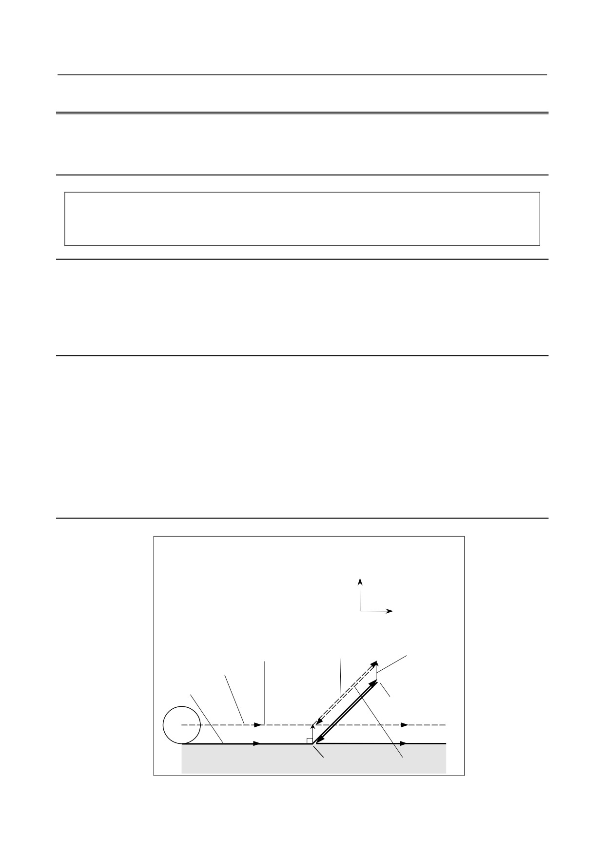
In tool radius / tool nose radius compensation, by specifying G38 in offset mode, it is possible to retain
the compensation vector at the end point of the previous block, without performing intersection
calculation.
Format
(In offset mode)
G38 IP_ ;
IP: Value specified for axial movement
Explanation
-
Vector retention
By specifying the above command, a vector is created at the end point of the block immediately
preceding the G38 block, vertical to that block. In the G38 block, the vertical vector output in the
previous block is retained. G38 is a one-shot G code. With the next move command without a G38
command, the compensation vector is re-created.
Limitation
-
Mode
Specify G38 in either G00 or G01 mode. If it is specified in G02 or G03 (circular interpolation) mode, a
radial error may occur at the start and end points.
-
Start-up/cancel
In start-up/cancel, the operation is as described in Subsections, “Tool Movement in Start-up” and “Tool
Movement in Offset Mode Cancel”. Thus, G38 cannot be specified in the following blocks:
1)
Start-up command (G41 or G42) block
2)
Cancel command (G40) block
3)
Block immediately preceding the cancel command (G40) block
Example
:
:
(In offset mode)
(G90)
N1 G38 X10.0 Y0.0 ;
Y axis
N2 G38 X15.0 Y5.0 ;
N3 G38 X10.0 Y0.0 ;
N4
X20.0 ;
:
X axis
:
Offset vector
Block N1
Block N2
Tool center path
Program command
(15.0, 5.0)
(10.0, 0.0)
Block N3
- 238 -

B-64484EN-2/02
PROGRAMMING
6.COMPENSATION FUNCTION
6.8
CORNER CIRCULAR INTERPOLATION (G39)
By specifying G39 in offset mode during tool radius / tool nose radius compensation, corner circular
interpolation can be performed. The radius of the corner circular interpolation equals the compensation
value.
Format
In offset mode
G39 ;
I_ J_
G39
I_ K_
;
J_ K_
Explanation
-
Corner circular interpolation
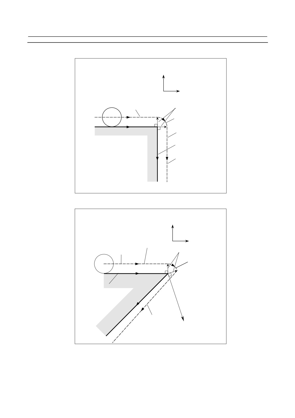
When the command indicated above is specified, corner circular interpolation in which the radius equals
compensation value can be performed. G41 or G42 preceding the command determines whether the arc is
clockwise or counterclockwise. G39 is a one-shot G code.
-
G39 without I, J, or K
When G39 is programmed, the arc at the corner is formed so that the vector at the end point of the arc is
perpendicular to the start point of the next block.
-
G39 with I, J, and K
When G39 is specified with I, J, and K, the arc at the corner is formed so that the vector at the end point
of the arc is perpendicular to the vector defined by the I, J, and K values.
Limitation
-
Move command
In a block containing G39, no move command can be specified. Otherwise, an alarm will occur.
-
Inner corner
In an inner corner block, G39 cannot be specified. Otherwise, overcutting will occur.
-
Corner arc velocity
If a corner arc is specified with G39 in G00 mode, the corner arc block velocity will be that of the F
command previously specified. If G39 is specified in a state in which no F command has never been
specified, the velocity of the corner arc block will be that specified with parameter No. 1411.
- 239 -
6.COMPENSATION FUNCTION
PROGRAMMING
B-64484EN-2/02
Example
-
G39 without I, J, or K
:
:
(In offset mode)
(G90)
Y axis
N1 X10.0
;
N2 G39 ;
N3 Y-10.0 ;
:
:
X axis
Block N1
Offset vector
Block N2 (Corner arc)
(10.0, 0.0)
Block N3
Programmed path
Tool center path
(10.0, -10.0)
-
G39 with I, J, and K
:
:
(In offset mode)
(G90)
Y axis
N1 X10.0 ;
N2 G39 I1.0 J-3.0 ;
N3 X0.0 Y-10.0 ;
:
X axis
:
Block N1
Tool center path
Offset vector
Block N2 (Corner
arc)
(10.0, 0.0)
Programmed
path
Block N3
(I=-1.0, J=3.0)
(0.0, -10.0)
- 240 -

B-64484EN-2/02
PROGRAMMING
6.COMPENSATION FUNCTION
6.9
3-DIMENSIONAL TOOL COMPENSATION (G40, G41)
In cutter compensation C, two-dimensional offsetting is performed for a selected plane. In 3-dimensional
tool compensation, the tool can be shifted 3-dimensionally when a 3-dimensional offset direction is
programmed.
Format
-
Start up (Starting 3-dimensional tool compensation)
When the following command is executed in the cutter compensation cancel mode, the
3-dimensional tool compensation mode is set:
G41 Xp_Yp_Zp_ I_ J_ K_D_ ;
Xp : X-axis or a parallel axis
Yp : Y-axis or a parallel axis
Zp : Z-axis or a parallel axis
I :
J :
See "Explanation".
K :
D
: Code for specifying as the cutter compensation value (1-3 digits) (D code)
-
Canceling 3-dimensional tool compensation
When the following command is executed in the 3-dimensional tool compensation
mode, the cutter compensation cancel mode is set:
- When canceling the 3-dimensional tool compensation mode and tool movement at
the same time
G40 Xp_Yp_Zp_ ;
or
Xp_Yp_Zp_ D00 ;
- When only canceling the vector
G40;
or
D00;
-
Selecting offset space
The 3-dimensional space where 3-dimensional tool compensation is to be executed is
determined by the axis addresses specified in the startup block containing the G41
command. If Xp, Yp, or Zp is omitted, the corresponding axis, X-, Y-, or Z-axis (the
basic three axis), is assumed.
(Example)
When the U-axis is parallel to the X-axis, the V-axis is parallel to the Y-axis, and the
W-axis is parallel to the Z-axis
G41 X_I_J_K_D_;
XYZ space
G41 U_V_Z_I_J_K_D_;
UVZ space
G41 W_I_J_K_D_;
XYW space
- 241 -
6.COMPENSATION FUNCTION
PROGRAMMING
B-64484EN-2/02
Explanation
-
3-dimensional tool compensation vector
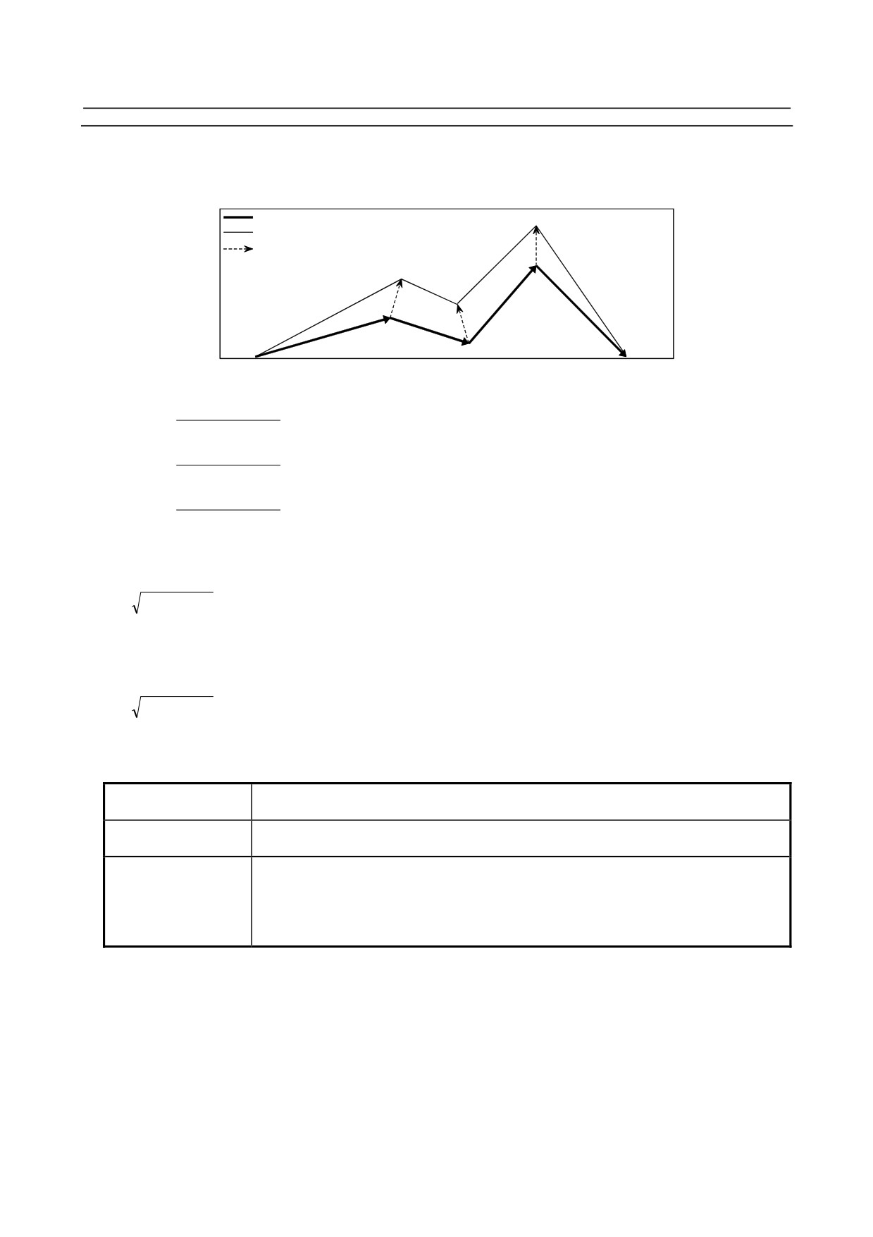
In 3-dimensional tool compensation mode, the following 3-dimensional tool compensation vector is
generated at the end of each block:
Programmed path
Path after three-dimensional cutter compensation
Three-dimensional cutter compensation
vector
G40
G41
The 3-dimensional tool compensation vector is obtained from the following expressions:
i
× r
Vx=
(Vector component along the Xp-axis)
p
j
× r
Vy=
(Vector component along the Yp-axis)
p
k × r
Vz=
(Vector component along the Zp-axis)
p
In the above expressions, i, j, and k are the values specified in addresses I, J, and K in the block. r is the
offset value corresponding to the specified offset number. p is the value obtained from the following
expression:
2
2
2
p=
i
+
j
+
k
When the user wants to program the magnitude of a 3-dimensional tool compensation vector as well as its
direction, the value of p in the expressions of Vx, Vy, and Vz can be set as a constant in parameter No.
5011.
If the parameter is set to 0, however, p is determined as follows:
2
2
2
p=
i
+
j
+
k
-
Relationship between 3-dimensional tool compensation and other
compensation functions
Tool length
The specified path is shifted by 3-dimensional tool compensation and the subsequent path
compensation
is shifted by tool length compensation.
When tool offset is specified in the 3-dimensional tool compensation mode, an alarm is
Tool offset
issued (alarm PS0042).
When addresses I, J, and K are all specified at startup, 3-dimensional tool compensation
mode is set. When not all of the addresses are specified, cutter compensation mode is
Cutter compensation
set. Therefore, cutter compensation cannot be specified in 3-dimensional tool
compensation mode and 3-dimensional tool compensation cannot be specified in cutter
compensation mode.
-
Specifying I, J, and K
Addresses I, J, and K must all be specified to start 3-dimensional tool compensation. When even one of
the three addresses is omitted, two-dimensional cutter compensation is activated. When a block specified
in 3-dimensional tool compensation mode contains none of addresses I, J, and K, the same vector as the
vector generated in the previous block is generated at the end of the block.
-
G42
Generally, G41 is specified to start 3-dimensional tool compensation. Instead of G41, G42 can be
specified for startup. With G42, 3-dimensional tool compensation is performed in the opposite direction.
- 242 -
B-64484EN-2/02
PROGRAMMING
6.COMPENSATION FUNCTION
-
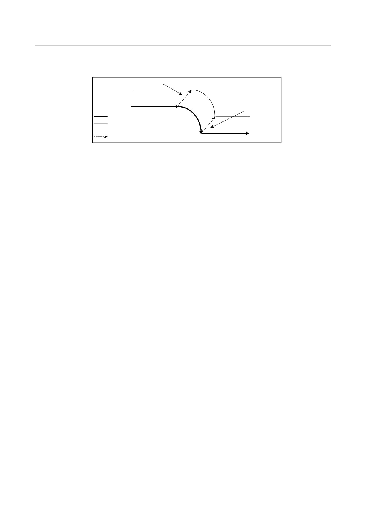
Offset vector in interpolation
When circular interpolation, helical interpolation
(both specified with G02, G03), or involute
interpolation (G02.2, G03.2) is specified, the vector generated in the previous block is maintained.
Vector generated in the block before an arc
The same vector is
generated.
Programmed path
Path after three-dimensional cutter
compensation
Three-dimensional cutter compensation vector
-
Reference position return check (G27)
Before specifying reference position return check (G27), cancel 3-dimensional tool compensation. In the
compensation mode, G27 brings the tool to a position shifted by the offset value. If the position the tool
reached is not the reference position, the reference position return LED does not go on (the alarm PS0092
alarm is issued).
-
Return to a reference position (G28, G30, G30.1)
When return to the reference position (G28), to the second, third, or fourth reference position (G30), or to
the floating reference position (G30.1) is specified, the vector is cleared at a middle point.
-
Alarm issued at startup
If one of the following conditions is present at the startup of 3-dimensional tool compensation, an alarm is
issued:
• Two or more axes are specified in the same direction. (alarm PS0047)
• Although Xp, Yp, or Zp is omitted, the basic three axes are not set. (alarm PS0048)
-
Alarm during 3-dimensional tool compensation
If one of the following G codes is specified in the 3-dimensional tool compensation mode, an alarm is
issued:
G05 High-speed cycle machining (alarm PS0178)
G31 Skip function (alarm PS0036)
G51 Scaling (alarm PS0141)
-
Commands that clear the vector
When one of the following G codes is specified in 3-dimensional tool compensation mode, the vector is
cleared:
G73 Peck drilling cycle
G74 Reverse tapping cycle
G76 Fine boring
G80 Canned cycle cancel
G81 Drilling cycle, spot boring
G82 Drilling cycle, counter boring
G83 Peck drilling cycle
G84 Tapping cycle
G85 Boring cycle
G86 Boring cycle
G87 Back boring cycle
G88 Boring cycle
G89 Boring cycle
G53 Machine coordinate system selection
- 243 -
6.COMPENSATION FUNCTION
PROGRAMMING
B-64484EN-2/02
-
Commands that generate the same vector as the vector in the previous block
When one of the following G codes is specified in 3-dimensional tool compensation mode, the same
vector as the vector generated in the previous block is generated at the end point of the next movement:
G02 Circular or helical interpolation (CW)
G03 Circular or helical interpolation (CCW)
G02.2 Involute interpolation (CW)
G03.2 Involute interpolation (CCW)
G04 Dwell
G10 Data setting
G22 Stored stroke check function enabled
6.10 TOOL COMPENSATION VALUES, NUMBER OF
COMPENSATION VALUES, AND ENTERING VALUES
FROM THE PROGRAM (G10)
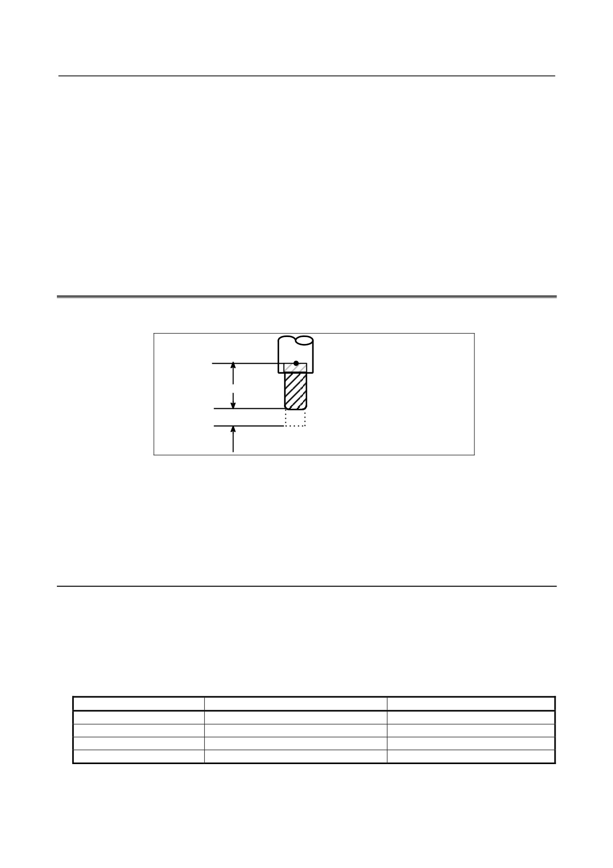
Tool compensation values include tool geometry compensation values and tool wear compensation (Fig.
6.10 (a)).
Reference
position
OFSG
OFSW
OFSG
: Geometry compensation value
OFSW
: Wear compensation value
Fig. 6.10 (a) Geometric compensation and wear compensation
Tool compensation values can be entered into CNC memory from the MDI panel (see section III-11.1.1)
or from a program.
A tool compensation value is selected from the CNC memory when the corresponding code is specified
after address H or D in a program.
The value is used for tool length compensation, cutter compensation, or the tool offset.
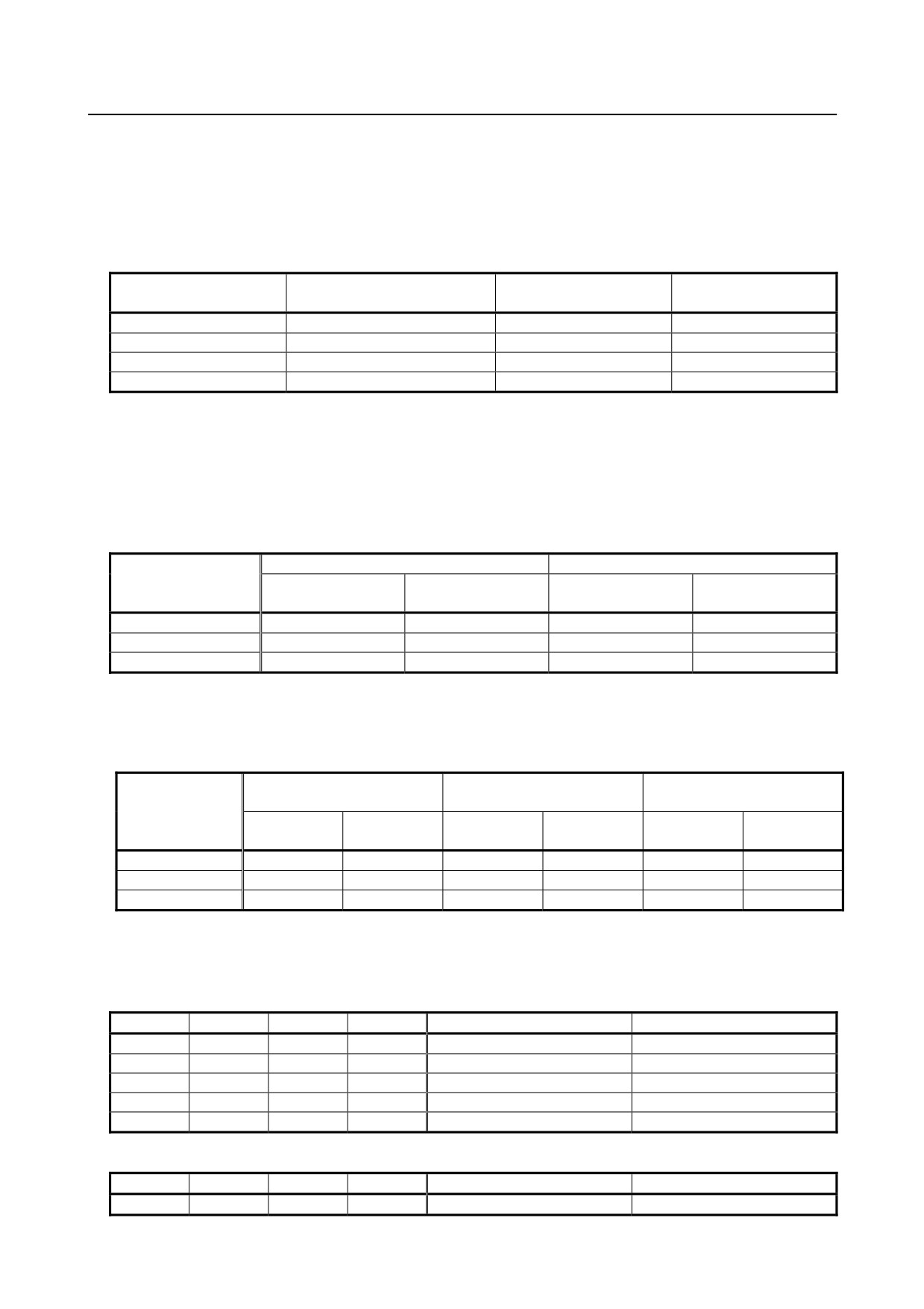
Three types of tool compensation memories are available according to the compensation value
configuration: tool compensation memory A, B, and C. One of the types can be selected.
Explanation
-
Tool compensation memory A
In tool compensation memory A, memory for geometry compensation and memory for wear
compensation are not distinguished from each other. So, the sum of geometry compensation and wear
compensation values is to be set in the compensation memory. Moreover, no distinction is made between
memory for cutter compensation (for D code) and memory for tool length compensation (for H code).
Setting example
Compensation number
Compensation value (geometry+wear)
Common to D code/H code
001
10.000
For D code
002
20.000
For D code
003
100.000
For H code
:
:
:
- 244 -
B-64484EN-2/02
PROGRAMMING
6.COMPENSATION FUNCTION
-
Tool compensation memory B
In tool compensation memory B, memory for geometry compensation and memory for wear
compensation are prepared separately. So, geometry compensation values and wear compensation values
can be set separately. However, no distinction is made between memory for cutter compensation (for D
code) and memory for tool length compensation (for H code).
Setting example
Common to D code/H
Compensation number
For geometry compensation
For wear compensation
code
001
10.100
0.100
For D code
002
20.200
0.200
For D code
003
100.000
0.100
For H code
:
:
:
:
-
Tool compensation memory C
In tool compensation memory C, memory for geometry compensation and memory for wear
compensation are prepared separately. So, geometry compensation values and wear compensation values
can be set separately. Moreover, memory for cutter compensation (for D code) and memory for tool
length compensation (for H code) are prepared separately.
Setting example
D code
H code
Compensation
For geometry
For wear
For geometry
For wear
number
compensation
compensation
compensation
compensation
001
10.000
0.100
100.000
0.100
002
20.000
0.200
200.000
0.300
:
:
:
:
:
In addition, if the cutting point command option is enabled, additional memory for corner R offset (for D
code) is prepared separately.
Setting example
D code
D code
H code
Compensation
(For tool compensation)
(For corner R offset)
number
For geometry
For wear
For geometry
For wear
For geometry
For wear
compensation
compensation
compensation
compensation
compensation
compensation
001
10.000
0.100
1.000
0.100
100.000
0.100
002
20.000
0.200
2.000
0.400
200.000
0.300
:
:
:
:
:
:
:
-
Unit and valid range of tool compensation values
A unit and valid range of tool offset values can be selected from the following by parameter setting:
Unit and valid range of tool compensation values (metric input)
OFE
OFD
OFC
OFA
Unit
Valid range
0
0
0
1
0.01mm
±9999.99mm
0
0
0
0
0.001mm
±9999.999mm
0
0
1
0
0.0001mm
±9999.9999mm
0
1
0
0
0.00001mm
±9999.99999mm
1
0
0
0
0.000001mm
±999.999999mm
Unit and valid range of tool compensation values (inch input)
OFE
OFD
OFC
OFA
Unit
Valid range
0
0
0
1
0.001inch
±999.999inch
- 245 -

6.COMPENSATION FUNCTION
PROGRAMMING
B-64484EN-2/02
OFE
OFD
OFC
OFA
Unit
Valid range
0
0
0
0
0.0001inch
±999.9999inch
0
0
1
0
0.00001inch
±999.99999inch
0
1
0
0
0.000001inch
±999.999999inch
1
0
0
0
0.0000001inch
±99.9999999inch
-
Number of tool compensation data items
The number of tool compensation data items used by the entire system varies from one machine to
another. Refer to the relevant manual of the machine tool builder.
Format
The format for programming depends on the type of tool compensation memory.
For tool compensation memory A
G10 L11 P_ R_ Q_ ;
P_
:
Tool compensation number
R_
:
Tool compensation value
Q_
:
Imaginary tool nose number
For tool compensation memory B
G10 L_ P_ R_ Q_ ;
L_
: Type of compensation memory
L10 : Geometry compensation value
L11 : Wear compensation value
P_
: Tool compensation number
R_ : Tool compensation value
Q_ : Imaginary tool nose number
For tool compensation memory C
G10 L_ P_ R_ Q_ ;
L_
: Type of compensation memory
L10 : Geometry compensation value corresponding to an H code
L11 : Wear compensation value corresponding to an H code
L12 : Geometry compensation value corresponding to a D code
L13 : Wear compensation corresponding to a D code
L110 : Geometry compensation value corresponding to a D code (for corner R
offset)
L111 : Wear compensation corresponding to a D code (for corner R offset)
P_
: Tool compensation number
R_ : Tool compensation value
Q_ : Imaginary tool nose number
By specifying G10, a tool compensation value can be set or modified.
When G10 is specified by absolute input (G90), the specified value is used as the new tool compensation
value.
When incremental input (G91) is used, a specified value added to the tool compensation value currently
set is used as the new tool compensation value.
- 246 -
B-64484EN-2/02
PROGRAMMING
6.COMPENSATION FUNCTION
NOTE
1 Address R follows the increment system for tool offset values.
2 If L is omitted for compatibility with the conventional CNC format, or L1 is
specified, the same operation as when L11 is specified is performed.
3 Set a imaginary tool nose number when the cutter compensation function is
specified and a imaginary tool nose direction is used.
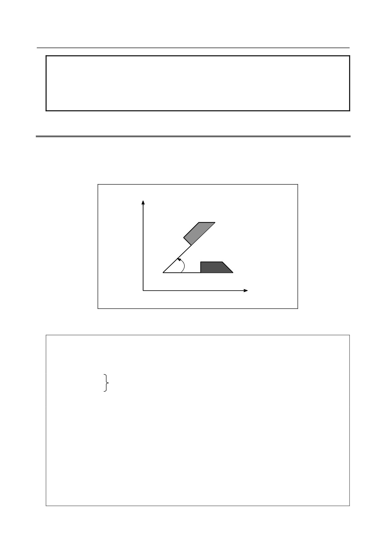
6.11 COORDINATE SYSTEM ROTATION (G68, G69)
A programmed shape can be rotated. By using this function it becomes possible, for example, to modify a
program using a rotation command when a workpiece has been placed with some angle rotated from the
programmed position on the machine. Further, when there is a pattern comprising some identical shapes
in the positions rotated from a shape, the time required for programming and the length of the program
can be reduced by preparing a subprogram of the shape and calling it after rotation.
Y
Angle of rotation
Center of rotation
X
0
Fig. 6.11 (a) Coordinate system rotation
Format
⎧G17
⎫
⎪
⎪
G18
Start rotation of a coordinate system.
⎨
⎬G68 α_β_ R_ ;
⎪
⎪
G19
⎩
⎭
:
Coordinate system rotation mode
:
(The coordinate system is rotated.)
G69 ;
Coordinate system rotation cancel command
G17 (G18 or G19) : Select the plane in which contains the figure to be rotated.
α_β_ : Absolute programming for two of the X_, Y_, and Z_ axes that correspond to the
current plane selected by a command (G17, G18, or G19). The command
specifies the coordinates of the center of rotation for the values specified
subsequent to G68
R_
: Angular displacement with a positive value indicates counter clockwise rotation.
Bit 0 (RIN) of parameter No. 5400 selects whether the specified angular
displacement is always considered an absolute value or is considered an
absolute or incremental value depending on the specified G code (G90 or G91).
Least input increment
:
0.001 deg
Valid data range
:
-360,000 to 360,000
- 247 -

6.COMPENSATION FUNCTION
PROGRAMMING
B-64484EN-2/02
Y
Angle of rotation R (incremental value)
Center of
Angle of rotation (absolute value)
rotation
(α, β)
X
Fig. 6.11 (b) Coordinate system rotation
NOTE
When a decimal fraction is used to specify angular displacement (R_), the 1's
digit corresponds to degree units.
Explanation
-
G code for selecting a plane: G17,G18 or G19
The G code for selecting a plane (G17,G18,or G19) can be specified before the block containing the G
code for coordinate system rotation (G68). G17, G18 or G19 must not be designated in the mode of
coordinate system rotation.
-
Incremental programming in coordinate system rotation mode
The center of rotation for an incremental programming programmed after G68 but before an absolute
programming is the tool position when G68 was programmed (Fig. 6.11 (c)).
-
Center of rotation
When α_β_ is not programmed, the tool position when G68 was programmed is assumed as the center of
rotation.
-
Angular displacement
When R_ is not specified, the value specified in parameter No. 5410 is assumed as the angular
displacement.
To specify angular displacement (R_) in 0.00001 degrees (one hundred-thousandth), set bit 0 (FRD) of
parameter No. 11630 to 1. In this case, angular displacement R is specified within the range of -36000000
to 36000000.
-
Coordinate system rotation cancel command
The G code used to cancel coordinate system rotation (G69) may be specified in a block in which another
command is specified.
-
Tool compensation
Tool radius/tool nose radius compensation, tool length compensation, tool offset, and other compensation
operations are executed after the coordinate system is rotated.
-
Relationship with 3-dimensional coordinate conversion (G68, G69)
Both coordinate system rotation and 3-dimensional coordinate conversion use the same G codes: G68 and
G69. The G code with I, J, and K is processed as a command for 3-dimensional coordinate conversion.
The G code without I, J, and K is processed as a command for two-dimensional coordinate system
rotation.
- 248 -

B-64484EN-2/02
PROGRAMMING
6.COMPENSATION FUNCTION
Limitation
-
Commands related to reference position return and the coordinate system
In coordinate system rotation mode, G codes related to reference position return (G27, G28, G29, G30,
etc.) and those for changing the coordinate system (G52 to G59, G92, etc.) must not be specified. If any
of these G codes is necessary, specify it only after canceling coordinate system rotation mode.
-
Incremental programming
The first move command after the coordinate system rotation cancel command (G69) must be specified
with absolute values. If an incremental move command is specified, correct movement will not be
performed.
-
Note on the specification of one axis in coordinate system rotation
With the parameter below, a move position in the case where one axis is specified in the absolute mode
can selected. If two axes are specified, a movement is made to the same position, regardless of the setting
of the parameter.
Bit 5 (AX1) of parameter No. 11600
If one axis is specified in the absolute mode when the coordinate system rotation mode is set:
0: The specified position is first calculated in the coordinate system before rotation then the
coordinate system is rotated.
1: The coordinate system is first rotated then a movement is made to the specified position in the
rotated coordinate system. (FS16i/18i/21i-compatible specification)
This parameter changes the handling of coordinates on axes not specified, so that a position to be
reached by movement changes.
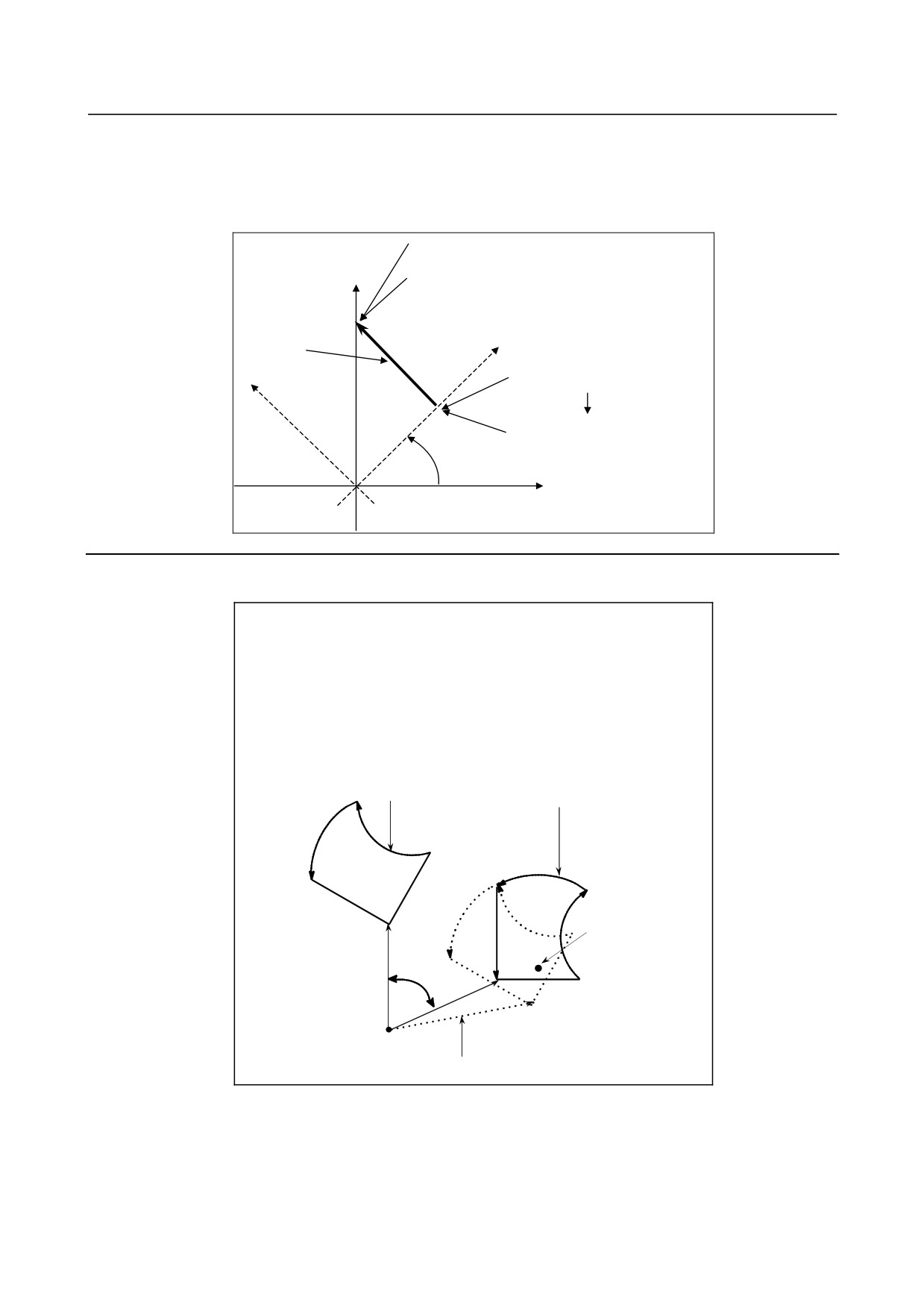
(Example)
G90 G0 X0 Y0
G01 X10. Y10. F6000
G68 X0 Y0 R45
Specifies coordinate system rotation.
Y14.142
Specifies one axis
(1)
G69
When bit 5 (AX1) of parameter No. 11600= 0:
The specified position is calculated in the coordinate system (XY) before rotation then the
coordinate system is rotated. So, with the specification of (1), the position on the unspecified X
axis is X10, and the specified position is (X10,Y14.142). Next, a movement is made to the
move position (X-2.929,Y17.071) obtained by 45° rotation.
Y
Move position
: X-2.929,Y17.071
Specified position
: X10,Y14.142
Coordinates before
Tool path
٨
45°
coordinate system rotation is
specified
: X10,Y10
X
- 249 -
6.COMPENSATION FUNCTION
PROGRAMMING
B-64484EN-2/02
When bit 5 (AX1) of parameter No. 11600= 1:
With the specification of (1), coordinates (X10,Y10) before coordinate system rotation are
converted to coordinates (X'14.142,Y'0) in the coordinate system (X'Y') obtained by 45°
rotation. Next, a movement is made to the specified position (X'14.142,Y'14.142), that is, the
move position (X0,Y20).
Specified position
: X'14.142,Y'14.142
Y
Move position
: X0,Y20
X'
Tool path
Coordinates before coordinate
system rotation is specified
Y'
: X10,Y10
٨
Conversion
Coordinates in rotated coordinate
system
45°
: X'14.142,Y'0
X
Explanation
-
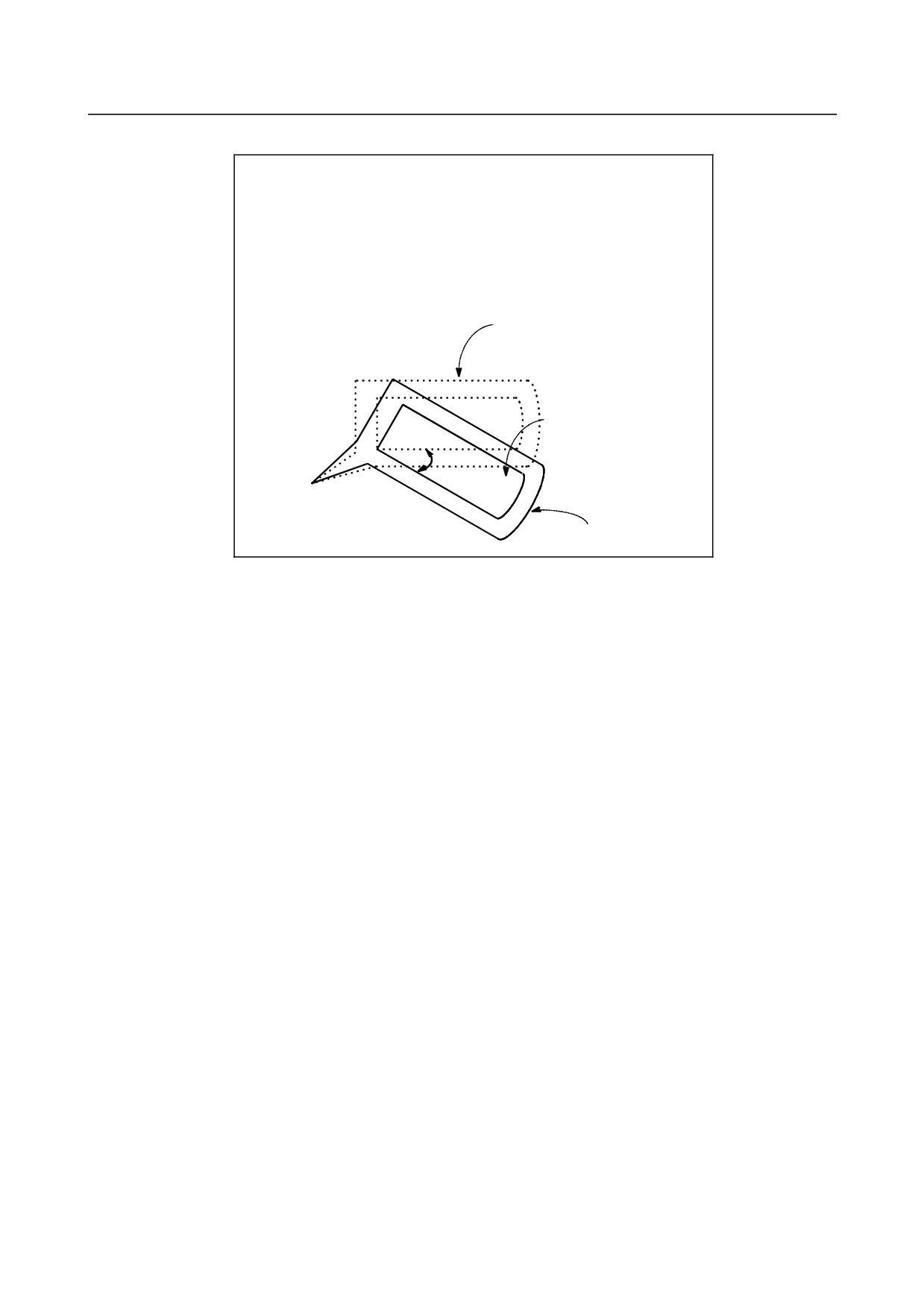
Absolute/Incremental position commands
N1 G92 X-500.0 Y-500.0 G69 G17 ;
N2 G68 X700.0 Y300.0 R60.0 ;
N3 G90 G01 X0 Y0 F200 ;
(G91X500.0Y500.0)
N4 G91 X1000.0 ;
N5 G02 Y1000.0 R1000.0 ;
N6 G03 X-1000.0 I-500.0 J-500.0 ;
N7 G01 Y-1000.0 ;
N8 G69 G90 X-500.0 Y-500.0 M02 ;
Tool path when the incremental
command is designated in the N3
block (in parenthesis)
Originally programmed tool path
Center of rotation
(700.0,300.0)
(0,0)
60º
(-500.0,-500.0)
Tool path after rotation
Fig. 6.11 (c) Absolute/incremental programming during coordinate system rotation
- 250 -
B-64484EN-2/02
PROGRAMMING
6.COMPENSATION FUNCTION
-
Cutter compensation and coordinate system rotation
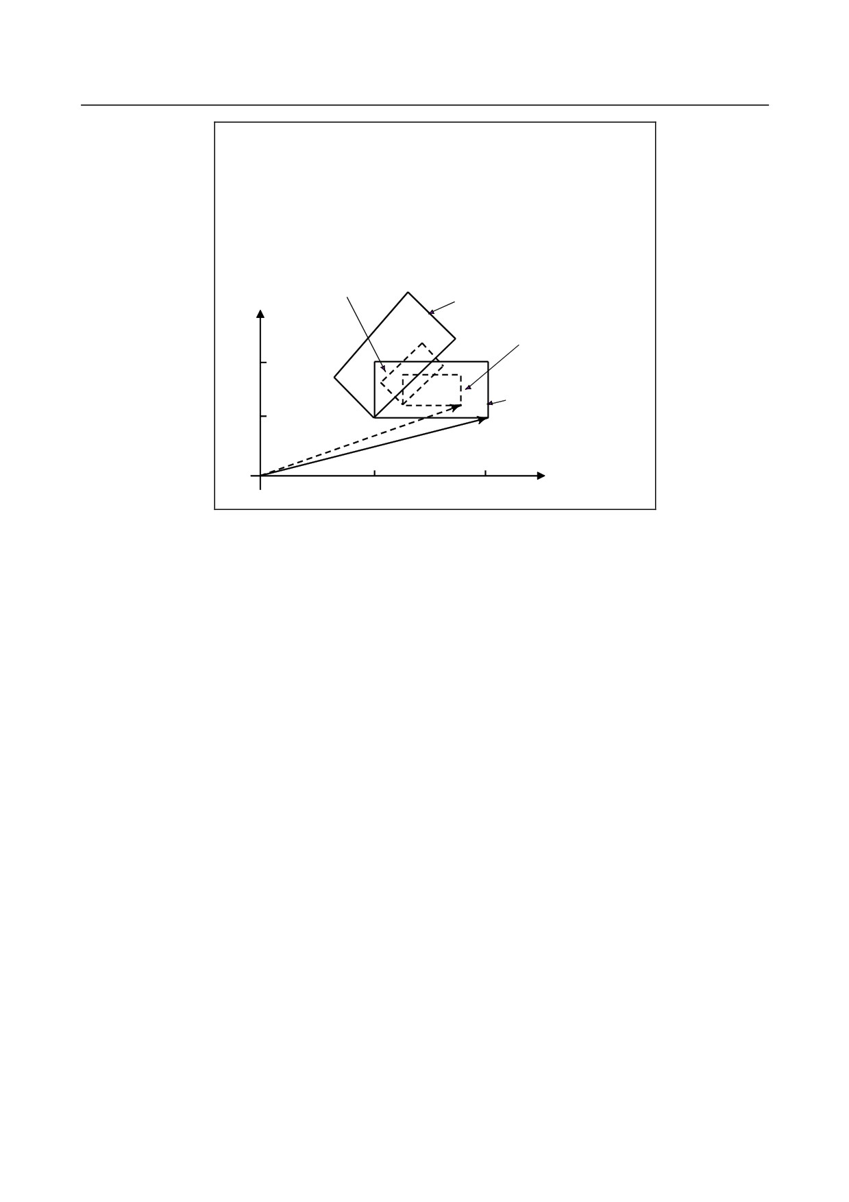
It is possible to specify G68 and G69 in cutter compensation mode.
The rotation plane must coincide with the plane of cutter compensation.
N1 G92 X0 Y0 G69 G01 ;
N2 G42 G90 X1000 Y1000 F1000 D01 ;
N3 G68 R-30000 ;
N4 G91 X2000 ;
N5 G03 Y1000 R1000 J500 ;
N6 G01 X-2000 ;
N7 Y-1000 ;
N8 G69 G40 G90 X0 Y0 M30 ;
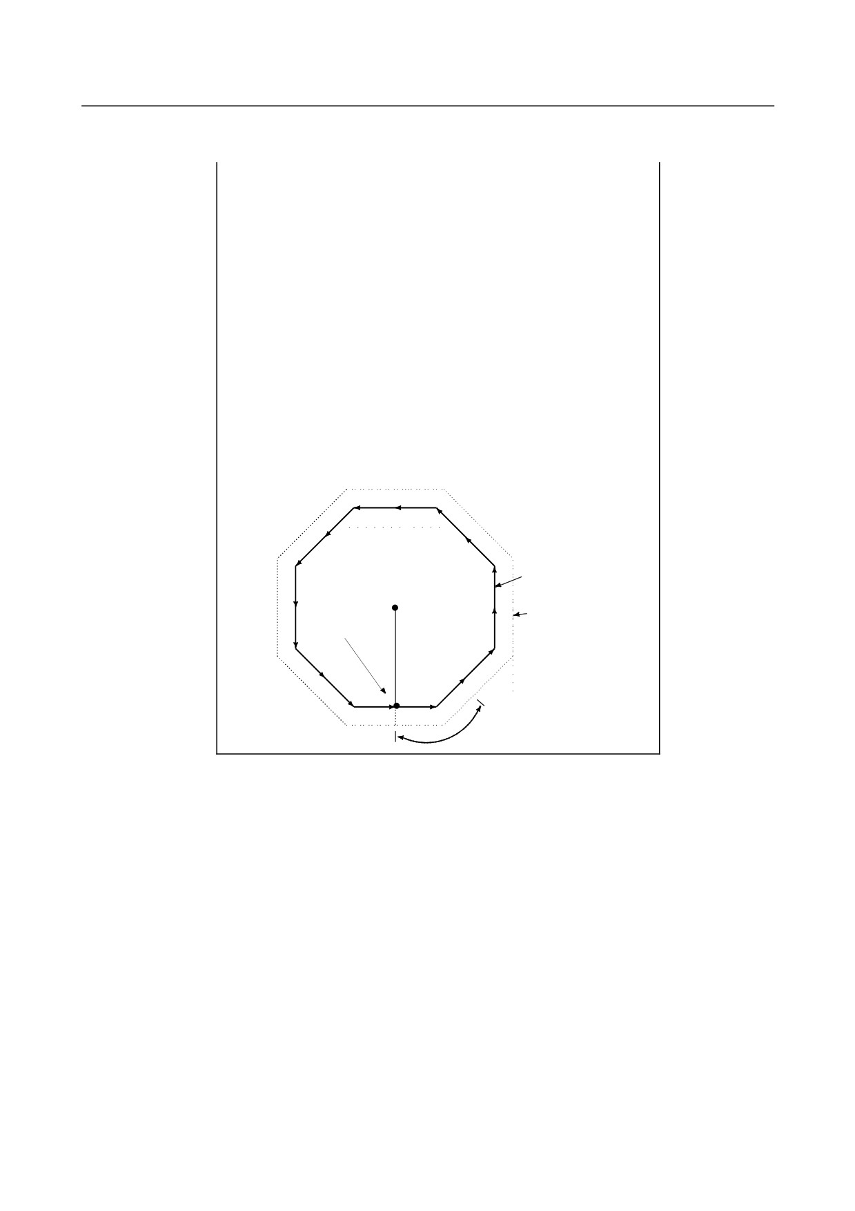
Programmed shape before
coordinate system rotation
Programmed shape
after coordinate
system rotation
30q
(0, 0)
Tool path
Fig. 6.11 (d) Cutter compensation and coordinate system rotation
-
Scaling and coordinate system rotation
If a coordinate system rotation command is executed in the scaling mode (G51 mode), the coordinate
value (a, b) of the rotation center will also be scaled, but not the rotation angle (R). When a move
command is issued, the scaling is applied first and then the coordinates are rotated.
A coordinate system rotation command (G68) should not be issued in cutter compensation mode (G41,
G42) on scaling mode (G51). The coordinate system rotation command should always be specified prior
to setting the cutter compensation mode.
1.
When the system is not in cutter compensation mode, specify the commands in the following order :
G51 ;
Scaling mode start
G68 ;
Coordinate system rotation mode start
:
G69 ;
Coordinate system rotation mode cancel
G50 ;
Scaling mode cancel
2.
When the system is in cutter compensation, specify the commands in the following order (Fig. 6.11
(e)) :
(cutter compensation cancel)
G51 ;
Scaling mode start
G68 ;
Coordinate system rotation start
:
G41 ;
Cutter compensation mode start
:
- 251 -
6.COMPENSATION FUNCTION
PROGRAMMING
B-64484EN-2/02
G92 X0 Y0 ;
G51 X300.0 Y150.0 P500 ;
G68 X200.0 Y100.0 R45.0 ;
G01 X400.0 Y100.0 ;
Y100.0 ;
X-200.0 ;
Y-100.0 ;
X200.0 ;
When scaling and coordinate
system rotation are applied
When only coordinate system
Y
rotation is applied
When only scaling is
applied
200.0
Cutting program
100.0
X
0
200.0
400.0
Fig. 6.11 (e) Scaling and coordinate system rotation in cutter compensation mode
- 252 -
B-64484EN-2/02
PROGRAMMING
6.COMPENSATION FUNCTION
-
Repetitive commands for coordinate system rotation
It is possible to store one program as a subprogram and recall subprogram by changing the angle.
Sample program for when parameter RIN (No. 5400#0) is set to 1.
The specified angular displancement is treated as an absolute or
incremental value depending on the specified G code (G90 or G91).
G92 X0 Y0 G69 G17;
G01 F200 H01 ;
M98 P2100 ;
M98 P072200 ;
G00 G90 X0 Y0 M30 ;
O 2200 G68 X0 Y0 G91 R45.0 ;
G90 M98 P2100 ;
M99 ;
O 2100 G90 G01 G42 X0 Y-10.0 ;
X4.142 ;
X7.071 Y-7.071 ;
G40 ;
M99 ;
Programmed path
(0, 0)
When offset is
applied
(0, -10.0)
Subprogram
Fig. 6.11 (f) Coordinate system rotation command
- 253 -
6.COMPENSATION FUNCTION
PROGRAMMING
B-64484EN-2/02
6.12 GRINDING WHEEL WEAR COMPENSATION
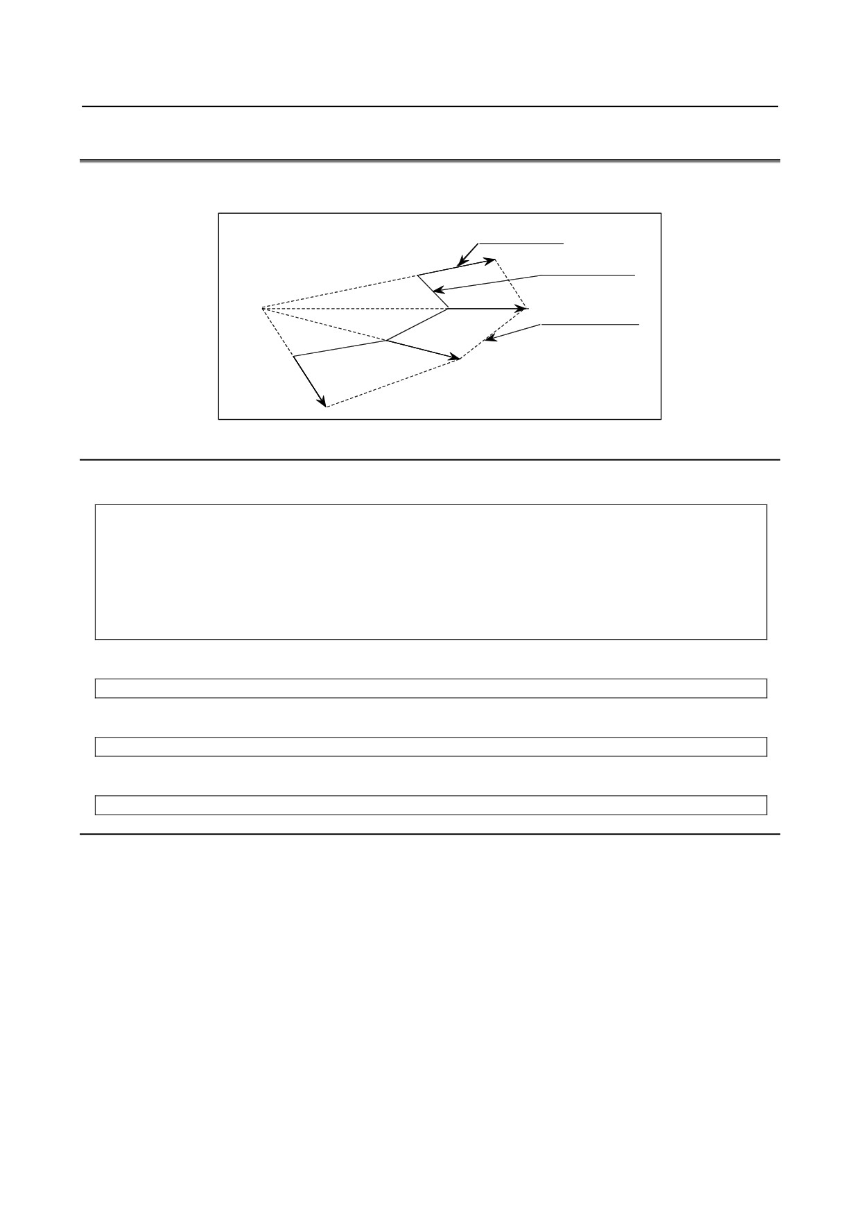
A compensation vector is created on an extension of the line from a specified point (compensation center)
to a specified end point position on a specified compensation plane.
Compensation vector
Programmed path
Compensation center
Tool center path
Fig. 6.12 (a)
Format
Compensation center selection
G41 P_(n=1,2,3);
G41P1: First compensation center selection Coordinates
(parameters Nos. 5081 and 5082))
G41P2: Second compensation center selection Coordinates
(parameters Nos. 5083 and 5084))
G41P3: Third compensation center selection Coordinates
(parameters Nos. 5085 and 5086))
Start-up
D_; non-zero D code
Compensation mode cancel
D0;
Compensation vector retention
G40;
Explanation
-
Compensation center setting and selection
There can be three compensation centers, and the coordinates of the centers can be set with parameters
Nos. 5081 to 5086.
Which of these three centers to use can be determined with G41Pn (where n = 1, 2, or 3).
G41 P1 ;
First compensation center selection
G41 P2 ;
Second compensation center selection
G41 P3 ;
Third compensation center selection
When selecting a compensation center, be sure to specify P1, P2, or P3 at the same time.
If no P is specified or if a value other than
1 to
3 is specified, alarm PS
1618,
“ILLEGAL
P-DATA(WHEEL WEAR COMPENSATION)” is issued.
The coordinates of the compensation centers (parameters Nos. 5081 to 5086) must be set as those in the
workpiece coordinate system.
- 254 -
B-64484EN-2/02
PROGRAMMING
6.COMPENSATION FUNCTION
Start-up
By specifying a compensation center and specifying a non-zero D code, the system enters compensation
mode.
Even if the block in which the D code is specified does not contain a move command, a compensation
vector is created and movement is performed.
-
Compensation vector
A compensation vector is created on an extension of the line from the compensation center to a specified
end point position, the length of the vector being equal to the offset value specified with its offset number
with a D code. (See Fig. 6.12 (a).)
If the offset value is positive, the compensation vector is added to the specified end point position, and if
the offset value is negative, the compensation vector is subtracted from the specified end point position.
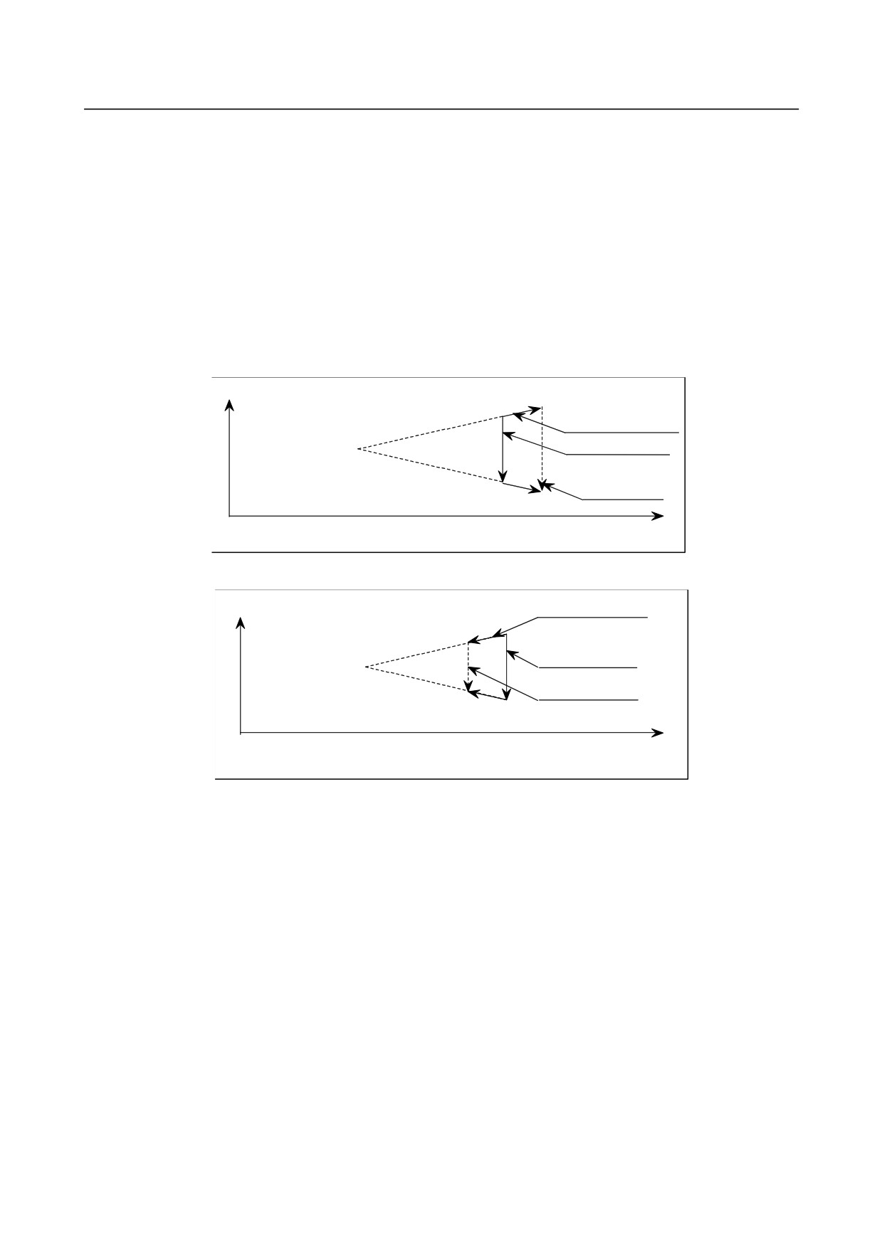
+
Z
Compensation vector (+)
Compensation
Programmed path
center
Tool center path
Y+
Fig. 6.12 (b) Offset value (+)
Compensation vector (-)
+
Z
Programmed path
Compensation
center
Tool center path
Y+
Fig. 6.12 (c) Offset value (-)
Compensation mode cancel
Specifying D0 causes the compensation mode to be canceled, so that the compensation vector is not
created.
-
Compensation vector retention
By specifying G40, it is possible to place the system in a mode in which the created compensation vector
is retained. Until the system enters the next new compensation mode, the specified end point position is
shifted by the vector.
If D0 is specified in the compensation vector retention mode, the retained vector is cleared and the
compensation mode is canceled.
-
Circular and helical interpolation
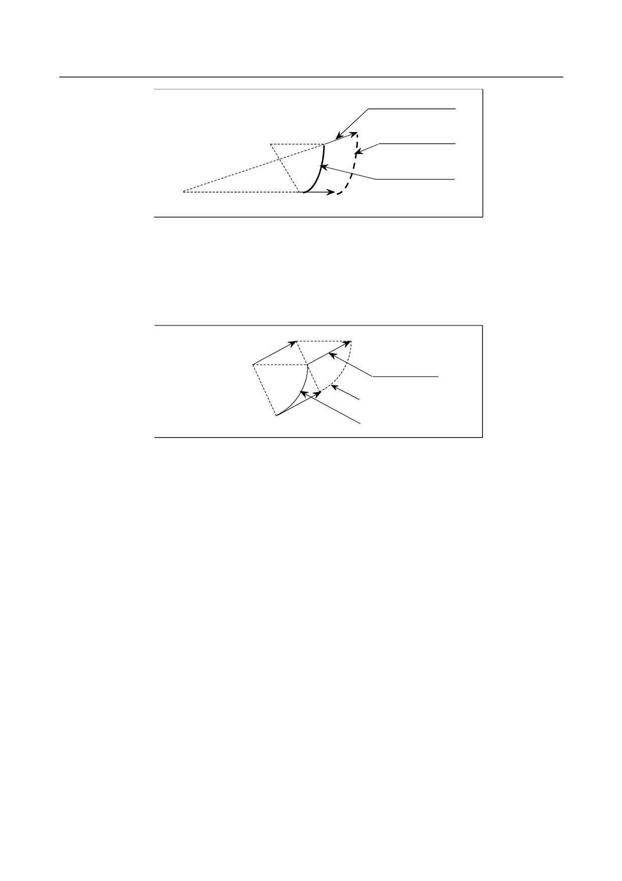
This compensation is also effective to circular interpolation. If the radius at the start point of the arc
differs from the radius at the end point, the arc cannot be a correct one. It will be a spiral one.
This is also true of helical interpolation.
- 255 -
6.COMPENSATION FUNCTION
PROGRAMMING
B-64484EN-2/02
Compensation vector
Arc center
Tool center path
Programmed path
Compensation center
Fig. 6.12 (d)
A check of the arc radius error limit (parameter No. 3410) is performed even on the value after
compensation.
-
Circular interpolation in G40 mode
Executing a G40 mode arc command causes the arc center to be shifted by the vector. This makes an arc,
not a spiral.
Programmed arc center
Retained vector
Tool center path
Programmed path
Fig. 6.12 (e)
Exponential interpolation
This compensation is also effective to exponential interpolation. Exponential interpolation is performed
on the position after compensation is applied.
-
Compensation plane and plane selection with G17/G18/G19
In the compensation mode (and in the compensation vector retention mode), a compensation vector is
constantly created for the axes on the compensation plane determined with a parameter. Creation of a
compensation vector is not related to the plane selection with G17/G18/G19.
It is possible to apply compensation on a compensation plane (for example, the YZ plane) while
performing circular interpolation on the XY (G17) plane.
If, in the compensation mode, a move command is issued for one compensation axis, and the
compensation vector components on the other axis are changed due to the creation of a compensation
vector, movement along this axis is performed.
- 256 -
B-64484EN-2/02
PROGRAMMING
6.COMPENSATION FUNCTION
(Example 1)
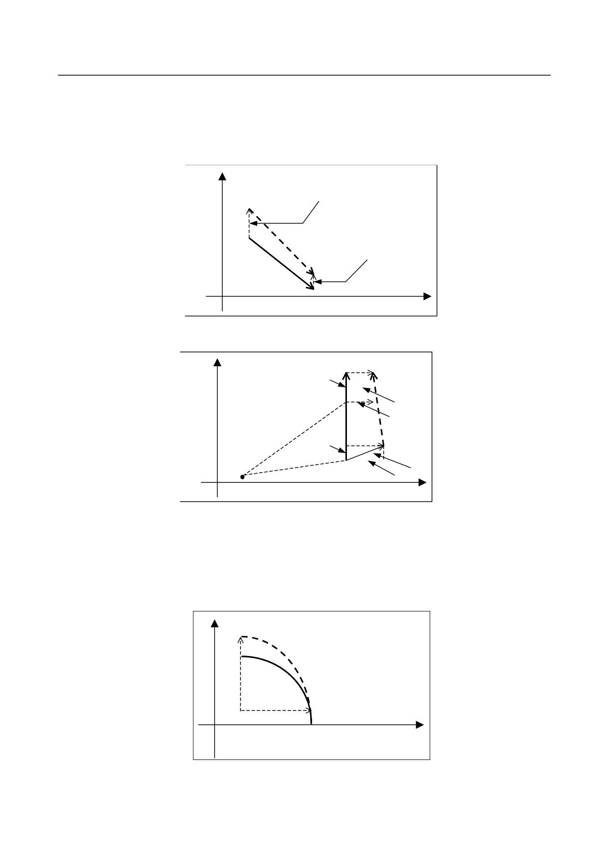
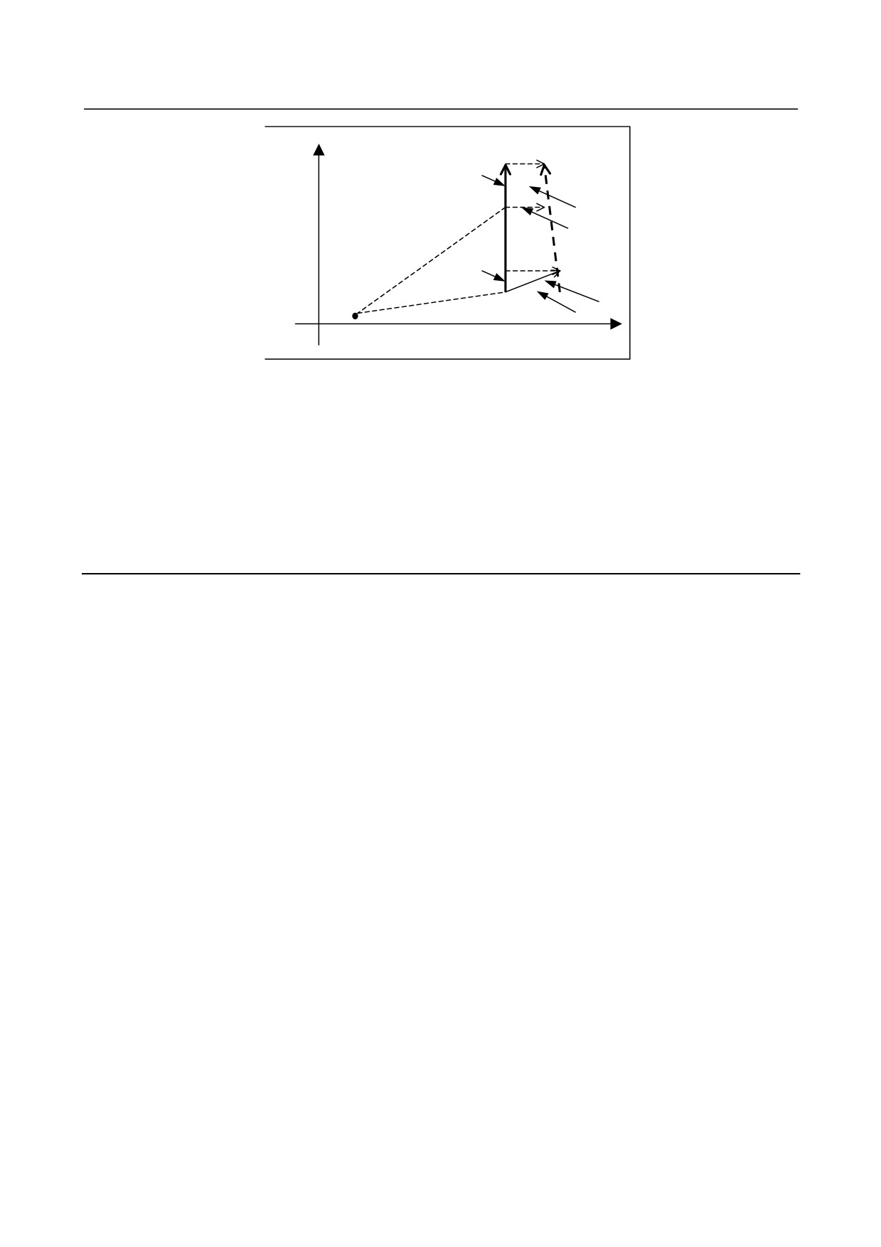
The compensation axes are set as the Y- and Z-axes, and a linear interpolation command is executed
on the X- and Y-axes.
Programmed path a → b
Path after compensation a’ → b’
Y
Vay
a'
a
Vby
b'
b
X
Fig. 6.12 (f) Path on the X-Y plane
Y
a
a'
Vay
Va
Vaz
Vby
b'
Vb
b
Vbz
Compensation center
Z
Vby
Fig. 6.12 (g) Path on the Y-Z plane
(Example 2)
The compensation axes are set as the Y- and Z-axes, and a circular interpolation
command is
executed on the X- and Y-axes.
Programmed path a → b
Path after compensation a’ → b’
Y
a'
a
b'
Arc center
b
X
Fig. 6.12 (h) Path on the X-Y plane
- 257 -
6.COMPENSATION FUNCTION
PROGRAMMING
B-64484EN-2/02
Y
a
a'
Vay
Va
Vaz
Vby
b'
Vb
b
Vbz
Compensation center
Vby
Z
Fig. 6.12 (i) Path on the Y-Z plane
-
Compensation cancel mode
Immediately after the power is turned on and after a reset, the system is in the compensation cancel mode.
-
Changing the coordinate system
To change the coordinate system, cancel the compensation mode first.
-
Return to the reference position (G28, G30)
To specify a return to the reference position (G28, G30), cancel the compensation mode.
Limitation
-
Relations with the coordinate conversion function
Functions such as programmable mirror image, scaling, and coordinate system rotation cannot be applied
to the coordinates of the compensation center.
-
Relations with other offset functions
In a system with this compensation attached, cutter compensation and 3-dimensional tool compensation
cannot be used. This compensation can be used simultaneously as tool length offset and tool offset.
-
Changing the compensation axis
To change the compensation axis, enter the compensation cancel mode.
- 258 -
B-64484EN-2/02
PROGRAMMING
6.COMPENSATION FUNCTION
6.13 ACTIVE OFFSET VALUE CHANGE FUNCTION BASED ON
MANUAL FEED
Overview
When rough machining/semifinish machining is to be performed using a single tool, you may make a fine
adjustment of a tool length compensation value or cutter compensation value. Moreover, at setup time,
you may want to make a fine adjustment of a workpiece origin offset once set. With this function, a travel
distance moved on an axis by manual feed is automatically added to the workpiece coordinate system or
the currently valid offset number among the specified offset values (tool length compensation value/cutter
compensation value/workpiece origin offset) to make a offset value change.
Explanation
-
Active offset value change mode
The active offset value change mode is set using the active offset value change mode signal. In this mode,
a travel distance moved on an axis by manual feed is automatically added to the workpiece coordinate
system or the currently valid offset number among the specified offset values (tool length compensation
value/cutter compensation value/workpiece origin offset). The types of manual feed usable to make an
offset value change in this mode are manual handle feed, incremental feed, and jog feed.
CAUTION
1 When a movement is being made on an axis for which an offset value is to be
changed, do not set the active offset value change mode.
2 In the active offset value change mode, do not reset the relative coordinate to 0
or preset the relative coordinate to a specified value.
-
Specifying an offset value to be changed
The active offset selection signal is used to specify one of three types of offset values: tool length
compensation value, cutter compensation value, and workpiece origin offset. In the active offset value
change mode, an offset value selected is indicated by blinking display in the state display area on the
screen as follows:
Offset value selected
State display
Tool length compensation value
LEN
Cutter compensation value
RAD
Workpiece origin offset
WZR
CAUTION
When a movement is being made on an axis for which an offset value is to be
changed in the active offset value change mode, do not change the specification
of the offset value to be changed.
-
Changing a tool length compensation value
The tool length compensation value with the offset number corresponding to an H code specified in
automatic operation is changed. If there is no currently valid tool length compensation value as in a case
where no H code is specified after a cycle start, no tool length compensation value change is made even
when a movement is made on an axis by manual feed.
With a movement on a linear axis, a tool length compensation value change can be made. With a
movement on a rotation axis, no tool length compensation value change can be made. While a tool length
compensation value is being changed, a movement by manual feed can be made on one axis only.
- 259 -
6.COMPENSATION FUNCTION
PROGRAMMING
B-64484EN-2/02
Example
- Specified H code: H10
- Value set with offset number 10: 54.700 mm
- Travel distance on the Z-axis by manual feed: -2.583 mm
In this example, the value of offset number 10 becomes:
54.700 + (-2.583) = 52.117 mm
CAUTION
A tool length compensation value can be changed by a movement on any linear
axis. When an offset value change for an axis is undesirable, interlock the axis.
NOTE
A changed tool length compensation value is handled according to bit 6 (EVO) of
parameter No. 5001 and bit 6 (AON) of parameter No. 5041.
-
Changing a cutter compensation value
The cutter compensation value with the offset number corresponding to a D code specified in automatic
operation is changed. If there is no currently valid cutter compensation value as in a case where no D
code is specified after a cycle start, no cutter compensation value change is made even when a movement
is made on an axis by manual feed.
With a movement on a linear axis, a cutter compensation value change can be made. With a movement on
a rotation axis, no cutter compensation value change can be made. While a cutter compensation value is
being changed, a movement by manual feed can be made on one axis only.
When operation is stopped in the cutter compensation mode to make a cutter compensation value change,
a movable travel distance on one axis is added, regardless of the direction of the compensation vector at
stop time.
Example
- Specified D code: H15
- Value set with offset number 15: 6.500mm
- Travel distance on the X-axis by manual feed: 2.379mm
- Travel distance on the Y-axis by manual feed: -0.572mm
In this example, the value of offset number 15 becomes:
6.500+2.379+(-0.572)= 8.307mm
CAUTION
A cutter compensation value can be changed by a movement on any linear axis.
When an offset value change for an axis is undesirable, interlock the axis.
NOTE
A changed cutter compensation value is handled according to bit 4 (EVR) of
parameter No. 5001.
-
Changing a workpiece origin offset value
The workpiece origin offset of the workpiece coordinate system corresponding to a G code from G54 to
G59 or from G54.1 P1 to P48 (300) specified during automatic operation is changed on an axis-by-axis
basis. A valid workpiece coordinate system exists at all times. So, when a movement is made on an axis
by manual feed, the workpiece origin offset of the workpiece coordinate system is changed without fail.
This change can be made by a movement on an arbitrary axis, which may be a linear axis or a rotation
axis. While a workpiece origin offset change is being made, movements can be made on multiple axes by
manual feed.
- 260 -
B-64484EN-2/02
PROGRAMMING
6.COMPENSATION FUNCTION
Example
- Specified workpiece coordinate system : G56
- Workpiece origin offset of G56 (X axis) : 50.000
- Workpiece origin offset of G56 (Y axis) : -60.000
- Workpiece origin offset of G56 (Z axis) : 5.000
- Workpiece origin offset of G56 (A axis) : 5.000
- Workpiece origin offset of G56 (B axis) : 15.000
- Travel distance on the X axis by manual feed : -10.000mm
- Travel distance on the Y axis by manual feed : -5.000mm
- Travel distance on the Z axis by manual feed : 10.000mm
- Travel distance on the A axis by manual feed : 8.000mm
- Travel distance on the B axis by manual feed : -2.000mm
In this example, the workpiece origin offsets of G56 are as follows:
- X axis : 50.000+(-10.000) = 40.000
- Y axis : -60.000+(-5.000) = -65.000
- Z axis : 5.000+10.000 = 15.000
- A axis : 5.000+8.000 = 13.000
- B axis : 15.000+(-2.000) = 13.000
-
Operation depending on each tool offset memory
Offset value change operation varies according to tool offset memory A/B/C as follows:
Tool offset
Changed offset value
memory
No distinction is made between a tool length compensation value and cutter compensation value.
A
The value specified with the offset number corresponding to the currently valid H code or D code is
changed.
No distinction is made between a tool length compensation value and cutter compensation value.
The value specified with the offset number corresponding to the currently valid H code or D code is
B
changed.
Depending on the setting of bit 4 (ASG) of parameter No. 5000, a geometry compensation value or
wear compensation value is changed.
The tool length compensation value and cutter compensation value specified with the offset numbers
corresponding to the currently valid H code and D code are changed.
C
Depending on the setting of bit 4 (ASG) of parameter No. 5000, a geometry compensation value or
wear compensation value is changed.
-
Presetting the relative position indication
By setting bit 5 (APL) of parameter No. 3115 to 1, the relative position indication (counter) can be
automatically preset to 0 when the active offset value change mode is selected. In this case, the changed
offset value can be restored to the original value by returning the relative position indication (counter) to
0 by manual feed.
-
Emergency stop, servo alarm
If an emergency stop occurs, a servo alarm is issued, or servo excitation is turned off, an offset value
change is made also for a travel distance on an axis moved by follow-up in the active offset value change
mode.
NOTE
If a tool length compensation value or cutter compensation value is selected as
an offset value to be changed, no offset value change is made for a travel
distance on a rotation axis moved by follow-up.
- 261 -