FANUC Series 0i-MODEL D, FANUC Series 0i Mate-MODEL D. MAINTENANCE MANUAL - page 7

4. MATTERS COMMON TO BOTH LCD-MOUNTED TYPE
AND STAND-ALONE TYPE (HARDWARE)
B-64305EN/03
Condition
LCD-mounted type control unit
Stand-alone type control unit
Meters above sea
Operating
Up to 1000 m (Note)
level
Non-operating
Up to 12000 m
Prevent coolant, lubricant, and chippings from being applied directly to on
Atmosphere
the control unit. Make sure that corrosive gas is not present.
NOTE
If the CNC is installed 1000 m or higher above sea level, the allowable upper
ambient temperature of the CNC in the cabinet is changed as follows.
Assume that the allowable upper ambient temperature of the CNC in the cabinet
installed 1000 m or higher above sea level decreases by 1.0°C for every 100 m
rise in altitude.
Example)
The upper allowable ambient temperature of the CNC in the cabinet installed
1750 m above sea level is:
55°C-1750/100 ×1.0°C=47.5°C
Therefore, the allowable ambient temperature range is from 0°C to 47.5°C.
When a hard disk is used, the following installation height conditions are applied:
Meters above sea level in the operating state
-60 to 3000m
Meters above sea level in the non-operating state
-60 to 12000m
4.9
COUNTERMEASURES AGAINST NOISE
The CNC has been steadily reduced in size using surface-mount and custom LSI technologies for
electronic components. The CNC also is designed to be protected from external noise. However, it is
difficult to measure the level and frequency of noise quantitatively, and noise has many uncertain factors.
It is important to prevent both noise from being generated and generated noise from being introduced into
the CNC. This precaution improves the stability of the CNC machine tool system.
The CNC component units are often installed close to the parts generating noise in the power magnetics
cabinet. Possible noise sources into the CNC are capacitive coupling, electromagnetic induction, and
ground loops.
When designing the power magnetics cabinet, guard against noise in the machine as described in the
following section.
4.9.1
Grounding
Grounding the power magnetics cabinet and devices is very important to prevent an electric shock and
suppress a noise influence. The following describes the grounding methods for suppressing the noise
influence.
4.9.1.1 About grounding types
The CNC system uses the following three types of grounding:
(1) Signal grounding
This type of grounding is used to supply a reference potential (0 V) for the electrical signal system.
(2) Frame grounding
This type of grounding is used for safety reasons as well as to suppress external and internal noise.
For example, grounding is provided for the device frames, panels, and shielding on the interface
cables connecting the devices.
- 164 -
4.MATTERS COMMON TO BOTH LCD-MOUNTED TYPE
B-64305EN/03
AND STAND-ALONE TYPE (HARDWARE)
(3) System grounding (PE)
This type of grounding is used to connect frame grounds, which are provided for the individual
devices or between the units, to the ground as a system at a single point.
4.9.1.2 Grounding methods
Typically, noise that becomes a problem is high-frequency noise. To suppress high-frequency noise, it is
important that the devices are grounded at low impedance(NOTE).
The grounding schemes for this purpose are described below.
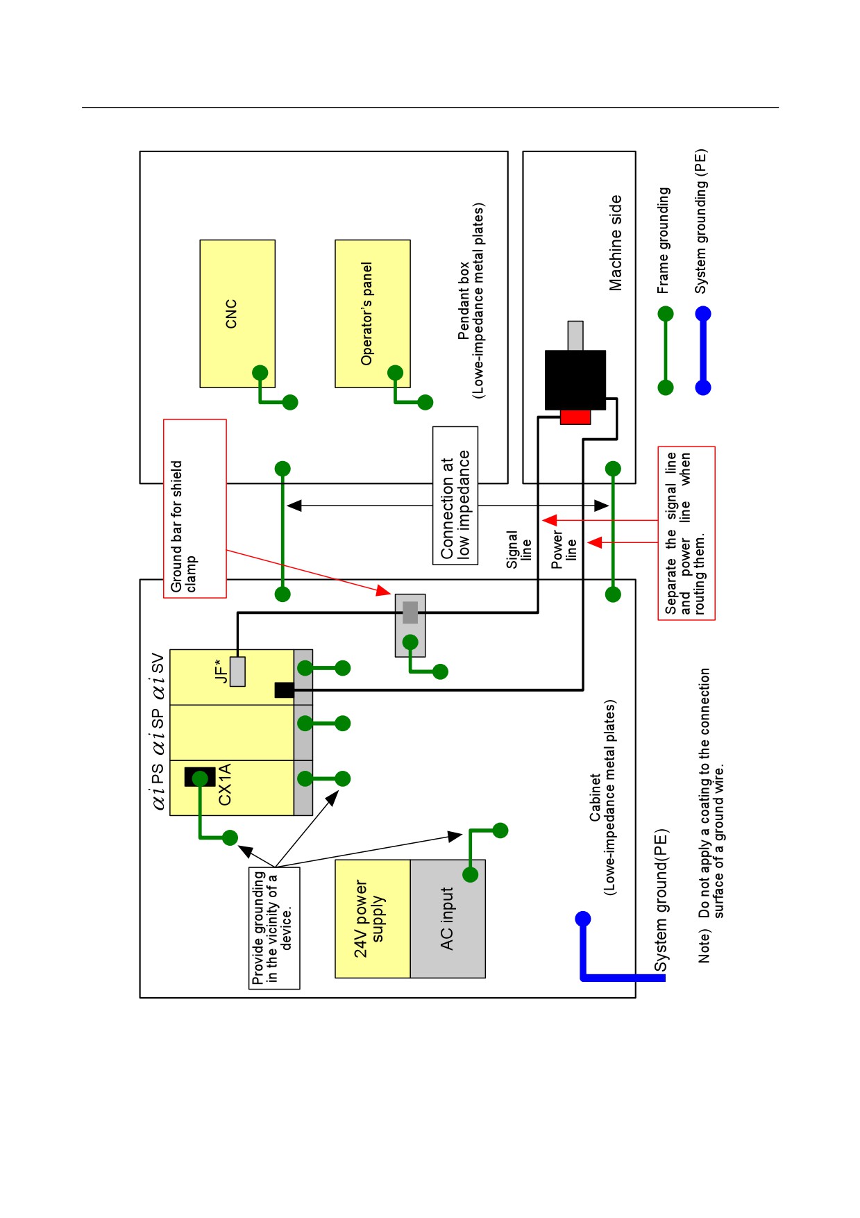
(1) Multipoint grounding scheme
In this grounding scheme, when grounded at sufficiently low impedance, the cabinet metal plates are
used as ground plates, to which grounding is provided in the vicinity of each device.
This scheme has a great effect of suppressing high-frequency noise because it enables grounding to
the low-impedance metal plates of the cabinet in the shortest distance. However, the noise
suppression effect depends on the cabinet structure because the cabinet metal plates are used as
ground plates.
See Subsection 4.9.1.4 for the cabinet. Fig. 4.9.1.2 (a) is a schematic wiring diagram.
When the multipoint grounding scheme is adopted, the units can be grounded at low impedance, and
ground wires can be shortened, so that wiring may be simplified.
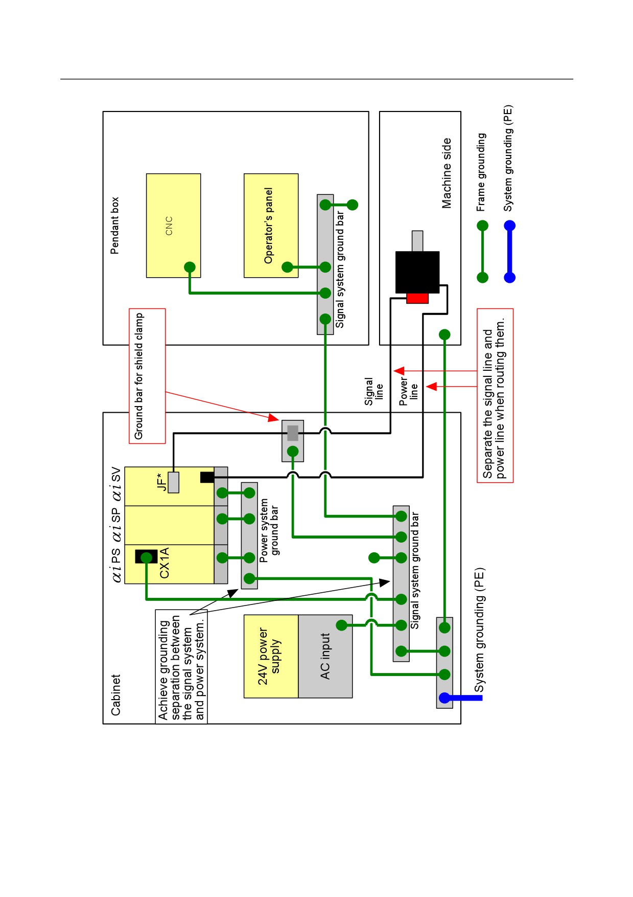
(2) Single-point grounding scheme
In this grounding scheme, grounding separation is achieved between the signal system and power
system, and grounding is provided at a single point to suppress the noise influence of the power
system on the signal system.
This scheme tends to need longer connection wires for grounding the devices. To produce a
sufficient effect of suppressing high-frequency noise, it is therefore necessary to use larger-diameter
wires or use two or more wires for each connection. Fig. 4.9.1.2 (b) is a schematic wiring diagram.
NOTE
Impedance includes a resistance component that converts electric current to
heat as well as a component called “reactance”, and indicates a characteristic of
resistance to the flow of alternating current at a certain frequency.
- 165 -
4. MATTERS COMMON TO BOTH LCD-MOUNTED TYPE
AND STAND-ALONE TYPE (HARDWARE)
B-64305EN/03
Fig. 4.9.1.2 (a) Schematic diagram for multipoint grounding scheme
- 166 -
4.MATTERS COMMON TO BOTH LCD-MOUNTED TYPE
B-64305EN/03
AND STAND-ALONE TYPE (HARDWARE)
Fig. 4.9.1.2 (b) Schematic diagram for single-point grounding scheme
- 167 -
4. MATTERS COMMON TO BOTH LCD-MOUNTED TYPE
AND STAND-ALONE TYPE (HARDWARE)
B-64305EN/03
4.9.1.3 Cable clamp and shield processing
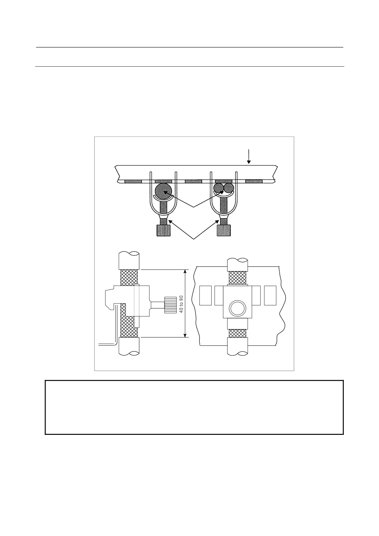
Signal lines basically require shield clamps. The influence of external noise can be suppressed by
properly providing the signal lines with the shield clamps.
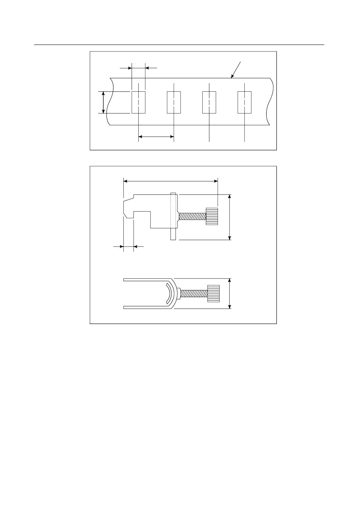
Partially peel the sheath off a cable and expose the shield, and press the exposed portion against the
ground bar with the clamp. Care should be taken so that the ground bar and shield have a surface contact
in a larger area. (See the figure below.)
When the multipoint grounding scheme is used, care should be taken so that the ground bar for the shield
clamp and cabinet are connected at low impedance by, for example, preventing the cabinet side contact
surface from being coated.
Ground plate
Cable
Metal fittings for
clamp
NOTE
Select a cable with a proper length.
If the cable is too long, the noise immunity may be reduced or noise may be
caused on other cables. In addition, when the excess length is coiled, the
inductance is increased and a high voltage is induced during turning on or off of
signals. This may cause a malfunction due to a failure or noise.
- 168 -
4.MATTERS COMMON TO BOTH LCD-MOUNTED TYPE
B-64305EN/03
AND STAND-ALONE TYPE (HARDWARE)
Machine side
installation board
Control unit
Ground plate
Metal fittings for
clamp
Shield cover
NOTE
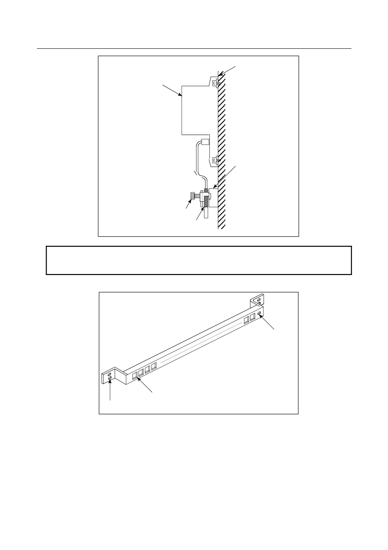
Bundle the cables connected to a CNC or amplifier near each unit and shield
them.
Prepare ground plate like the following figure.
Ground terminal
(grounded)
Hole for securing
metal fitting clamp
Mount screw hole
For the ground plate, use a metal plate of 2 mm or thicker, which surface is plated with nickel.
- 169 -
4. MATTERS COMMON TO BOTH LCD-MOUNTED TYPE
AND STAND-ALONE TYPE (HARDWARE)
B-64305EN/03
Ground plate
8mm
12
mm
20mm
(Reference) Outer drawings of metal fittings for clamp.
Up to 55mm
28mm
6
mm
17mm
Ordering specification for metal fittings for clamp
A02B-0124-K001 (8 pieces)
- 170 -
4.MATTERS COMMON TO BOTH LCD-MOUNTED TYPE
B-64305EN/03
AND STAND-ALONE TYPE (HARDWARE)
4.9.1.4 Cabinet
A cabinet is an important element in improving noise immunity and suppressing radiated noise. One of
the causes of problems related to noise immunity and radiated noise is faulty electrical continuity between
the metal plates that make up the cabinet. Typically, noise that becomes a problem is high-frequency
noise, against which measures must be taken in the cabinet design.
(1) Basic cabinet structure
A cabinet should basically be made of metal.
To improve noise immunity, there must be low-impedance electrical continuity between the metal
plates that make up the cabinet, which are the side plates, top plate, and bottom plate, and a
welding-type cabinet structure is recommended.
As for a cabinet welding method, bead welding is more suitable than spot welding for providing
low-impedance electrical continuity between the metal plates.
For an assembly-type cabinet structure, provide electrical continuity by bringing the metal plates
into direct contact with each other, without applying a coating to their joint surface areas.
In a structure that has the metal plates connected only with wires because of structural constraints,
low-impedance connections are more difficult to make than in a structure in which welding is made
or the metal plates are brought into direct contact with each other. It is necessary to maintain
sufficient levels of items such as the cross-sectional area of a wire to use, continuity of connections,
and contact areas.
Bead welding
Bring the metal plates into direct contact with each
other, without applying a coating to their joint areas.
NOTE
For improved noise immunity, how to provide low-impedance electrical continuity
in the cabinet is described here. To construct a protective circuit, a protective
grounding connection must be made between the metal plates by using electric
wires with a cross-sectional area appropriate for the AC input power capacity of
the unit mounted on each metal plate.
(2) Mounting units on the cabinet
The shortest possible lengths of unit ground wires should be used to make connections. A ground
wire with a small conductor diameter causes impedance to high-frequency noise to become
particularly higher, leading to an insufficient grounding effect. For the location of the ground
terminal of each unit, refer to the manual relevant to the unit. The following shows the
recommended method by which the metal plate with the unit mounted is installed on the cabinet.
Care should be taken so that the cabinet and metal plate are connected to each other on their broad
areas with no coating. It is not recommended that electrical continuity be provided only by screws,
because impedance to high frequency cannot be sufficiently low.
- 171 -
4. MATTERS COMMON TO BOTH LCD-MOUNTED TYPE
AND STAND-ALONE TYPE (HARDWARE)
B-64305EN/03
<Good example>
Cabinet
Metal
plate
Unit
Shortest connection
Continuity on areas with
with thick ground wire
no coating
<Bad example>
Cabinet
Metal
plate
Unit
Continuity only by
Thin ground wire,
screw in a coated area
long ground wire
- 172 -
4.MATTERS COMMON TO BOTH LCD-MOUNTED TYPE
B-64305EN/03
AND STAND-ALONE TYPE (HARDWARE)
4.9.2
Connecting the Ground Terminal of the Control Unit
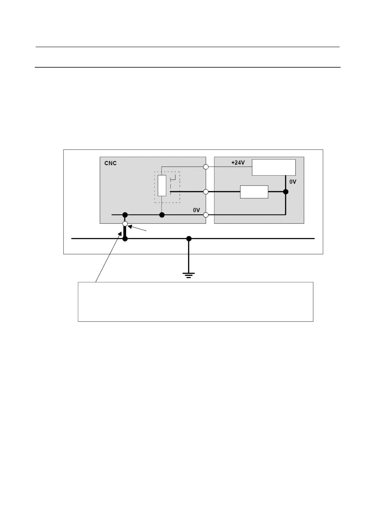
Connecting the 0 V output in the CNC to a protective circuit (ground)
The IEC 204-1 and JIS B 6015 standards specify the following:
- Protection against malfunctions due to ground faults
“To make the control circuit prevent malfunctions of a machine tool due to a ground fault and not to
prevent the machine tool from stopping, either of the ground and electronic circuits shall be connected to
a protective circuit.”
Note that for each FANUC CNC, the 0V output in the CNC is connected to a protective circuit (ground).
Machine
24 VDC power
supply
Power
magnetics
Output
cabinet
signal
Relay
NC ground terminal
Machine protective circuit (ground) network
Connection to the ground in the user factory
This bold line indicates grounding for the control unit described in the connection manual.
As shown in this figure, by just connecting the ground terminal of the control unit to the machine ground,
the 0 V output of the relay circuit in the power magnetics cabinet is connected to the ground (protective
circuit).
- 173 -
4. MATTERS COMMON TO BOTH LCD-MOUNTED TYPE
AND STAND-ALONE TYPE (HARDWARE)
B-64305EN/03
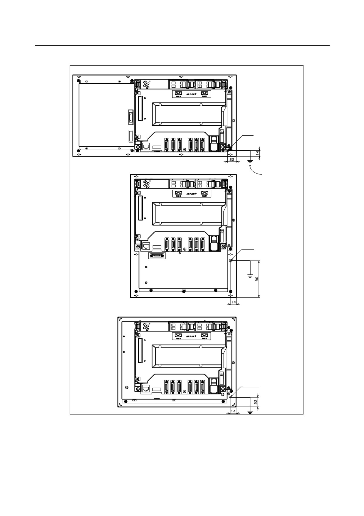
For LCD-mounted type control unit
For the 8.4" LCD/MDI (horizontal) type
Unit back face
M4 screw
For the 8.4" LCD/MDI (vertical) type
Grounding cable
Unit back face
M4 screw
For the 10.4" LCD type
Unit back face
M4 stud
Connect the 0-V line in the control unit to the ground plate of or a metal plate near the cabinet via the
protection ground terminal (above figure).
- 174 -
4.MATTERS COMMON TO BOTH LCD-MOUNTED TYPE
B-64305EN/03
AND STAND-ALONE TYPE (HARDWARE)
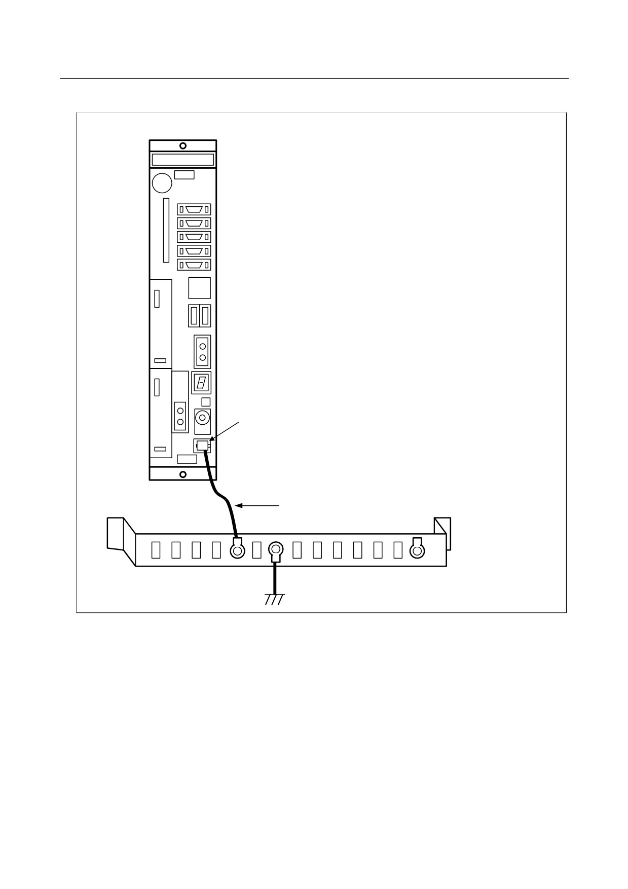
For stand-alone type control unit
For 2-slot rack
Protection ground terminal
(Faston terminal)
Ground cable
2mm2 or more
Grounding plate of
the cabinet
Ì
PE
Connect the 0-V lines of the electronic circuits in the control unit to the ground plate of the cabinet via the
protection ground terminal (above figure).
Use the Faston terminal (FANUC specification: A02B-0166-K330).
- 175 -
4. MATTERS COMMON TO BOTH LCD-MOUNTED TYPE
AND STAND-ALONE TYPE (HARDWARE)
B-64305EN/03
4.9.3
Separating Signal Lines
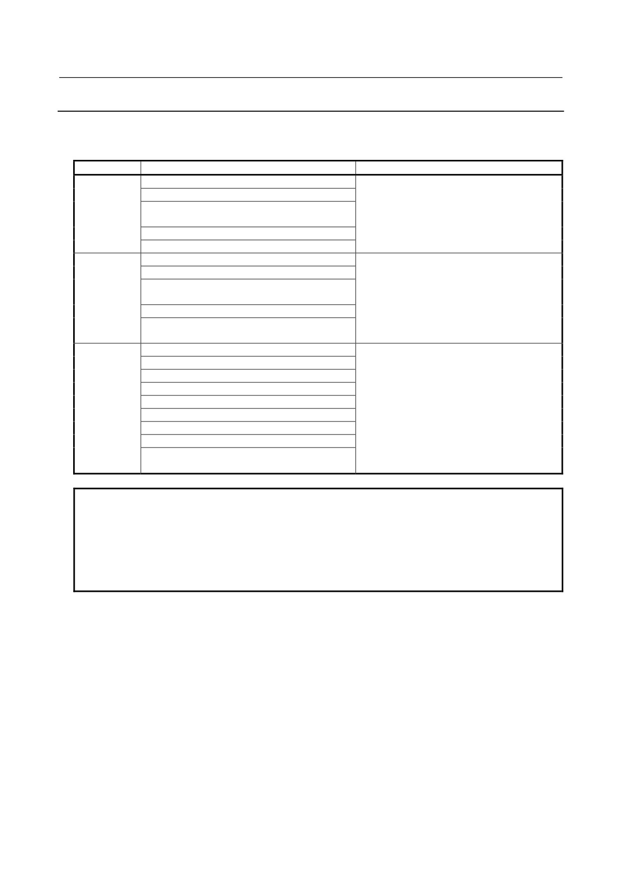
The cables used for the CNC machine tool are classified as listed in the following table.
Process the cables in each group as described in the action column.
Group
Signal line
Action
A
Primary AC power line
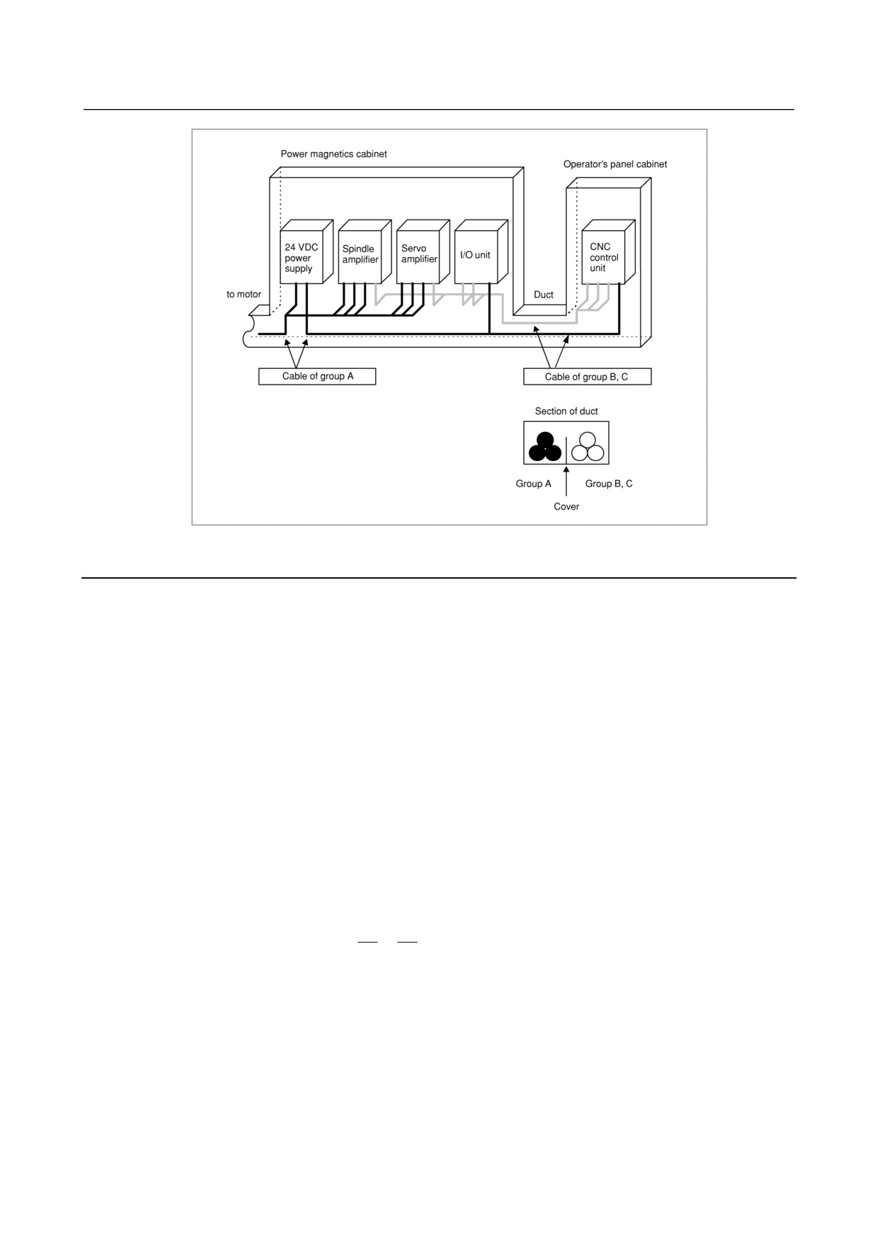
Bind the cables in group A separately (Note 1)
Secondary AC power line
from groups B and C, or cover group A with an
AC/DC power lines (containing the power lines for
electromagnetic shield (Note 2).
the servo and spindle motors)
See Subsection 4.9.4 and connect spark killers
AC/DC solenoid
or diodes with the solenoid and relay.
AC/DC relay
B
DC solenoid (24 VDC)
Connect diodes with the DC solenoid and relay.
DC relay (24 VDC)
Bind the cables in group B separately from
DI/DO cable between the I/O unit and power
group A, or cover group B with an
magnetics cabinet
electromagnetic shield.
DI/DO cable between the I/O unit and machine
Separate group B as far from group C as
24 VDC input power cables connected to the
possible.
control unit and its peripherals
It is desirable to perform shield processing.
C
Cable between the CNC and I/O unit
Bind the cables in group C separately from
Cable for position and velocity feedback
group A, or cover group C with an
Cable between the CNC and spindle amplifier
electromagnetic shield.
Cable for the position coder
Separate group C as far from group B as
Cable for the manual pulse generator
possible.
Be sure to perform shield processing as
Cable between the CNC and the MDI (Note 3)
described in Subsection 4.9.1.3.
RS-232C and RS-422 interface cable
Cable for the battery
Other cables for which shield processing is
specified
NOTE
1 Binding the cables in one group separately from another means that the groups
are placed 10 cm or more apart from one another.
2 Covering a group with an electromagnetic shield means that shielding is
provided between groups with grounded steel plates.
3 The shield is not required when the cable between the CNC and MDI is no more
than 30 cm in length.
- 176 -
4.MATTERS COMMON TO BOTH LCD-MOUNTED TYPE
B-64305EN/03
AND STAND-ALONE TYPE (HARDWARE)
4.9.4
Noise Suppressor
The AC/DC solenoid, AC/DC relay, and other devices are used in the power magnetics cabinet.
A high pulse voltage is caused by coil inductance when these devices are turned on or off.
This pulse voltage is induced through a cable or any other component, causing the electronic circuits to be
disturbed.
Take the following measures against the pulse voltage:
1)
See Subsection 4.9.3 for groups A and B, and use spark killers for AC circuits or diodes for DC
circuits.
2)
See “Notes on selecting the spark killer” below for information about selection of spark killers or
diodes.
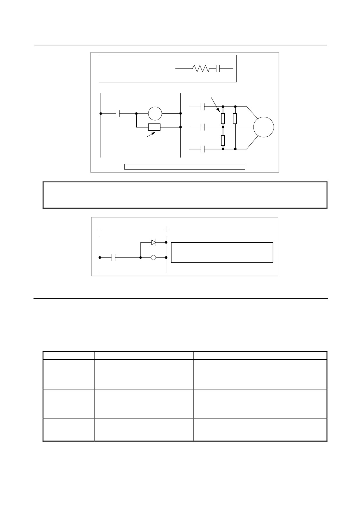
Notes on selecting the spark killer
• Use a CR-type spark killer. (Use it for AC circuits.)
(A varistor is useful in clamping the peak pulse voltage, but cannot suppress the sudden rise of the
pulse voltage. FANUC therefore recommends the use of a CR-type spark killer.)
• The reference CR values of the spark killer shall conform to the following based on the current ((I
(A)) and DC resistance of the coil in the stationary state:
1)
Resistance (R) :
Equivalent of the DC resistance of the coil
2
2
I
I
2)
Capacitance (C)
:
~
(μF)
10
20
I
:Current of the coil in the stationary state [A]
- 177 -
4. MATTERS COMMON TO BOTH LCD-MOUNTED TYPE
AND STAND-ALONE TYPE (HARDWARE)
B-64305EN/03
R
C
Equivalent circuit of the spark killer
Spark killer
AC relay
Motor
Spark killer
Mount the noise eliminator near a motor or a relay coil.
NOTE
Use a CR-type noise eliminator. Varistor-type noise eliminators clamp the peak
pulse voltage but cannot suppress a sharp rising edge.
Diode (used for direct-current circuits)
Diode
Use a diode which can withstand a voltage up
DC relay
to two times the applied voltage and a current
up to two times the applied current.
4.9.5
Measures Against Surges due to Lightning
To protect equipment from surge voltages caused by lightning, install a lightning surge protector between
lines and between a line and ground. For how to install protectors, see Appendix A "FITTING A
LIGHTNING SURGE PROTECTION DEVICE" in FANUC SERVO AMPLIFIER αi series
DESCRIPTIONS (B-65282EN).
Lightning surge protector specifications
Ordering number
Specification
Remarks
For line-to-line installation:
Manufactured by Okaya Electric Industries Co., Ltd.
RAV-781BYZ-2
A06B-6077-K142
For 200VAC line
For line-to-ground installation:
TÜV approved products
RAV-781BXZ-4
For line-to-line installation:
Manufactured by Okaya Electric Industries Co., Ltd.
RAV-152BYZ-2A
A06B-6077-K143
For 400VAC line
For line-to-ground installation:
TÜV approved products
RAV-801BXZ-4
Integration type for line-to-line
Manufactured by Okaya Electric Industries Co., Ltd.
A06B-6077-K144
installation/line-to-ground installation:
For 200VAC line
RCM-601BUZ-4
TÜV approved products
* The line-to-line or line-to-ground installation type (A06B-6077-K144) and the integration type
(A06B-6077-K142) are equivalent in performance and specifications.
- 178 -

4.MATTERS COMMON TO BOTH LCD-MOUNTED TYPE
B-64305EN/03
AND STAND-ALONE TYPE (HARDWARE)
4.10 REPLACING BATTERY FOR ABSOLUTE PULSECODERS
4.10.1 Overview
• When the voltage of the batteries for absolute Pulsecoders becomes low, alarm 307 or 306 occurs,
with the following indication in the CNC state display at the bottom of the CNC screen.
Alarm 307 (alarm indicating the voltage of the battery becomes low) :
The indication "APC" blinks in reversed display.
Alarm 306 (battery zero alarm) :
The indication "ALM" blinks in reversed display.
• When alarm 307 (alarm indicating the voltage of the battery becomes low) occurs, replace the
battery as soon as possible. In general, the battery should be replaced within one or two weeks,
however, this depends on the number of Pulsecoders used.
• When alarm 306 (battery zero alarm) occurs, Pulsecoders are reset to the initial state, in which
absolute positions are not held. Alarm 300 (reference position return request alarm) also occurs,
indicating that reference position return is required.
• In general, replace the batteries periodically within the service life listed below.
-
A06B-6050-K061 or D-size alkaline dry cells (LR20) : Two years
(for each six-axis
configuration)
-
A06B-6073-K001 : Two years (for each three-axis configuration)
-
A06B-6114-K504 : One year (for each three-axis configuration)
NOTE
The above values indicate the estimated service life of batteries used with
FANUC absolute Pulsecoders. The actual battery service life depends on the
machine configuration based on, for example, detector types. For details, contact
the machine tool builder.
4.10.2 Replacing Batteries
To prevent absolute position information in absolute Pulsecoders from being lost, turn on the machine
power before replacing the battery. The replacement procedure is described below.
<1> Ensure that the power to the servo amplifier is turned on.
<2> Ensure that the machine is in the emergency stop state (the motor is inactive).
<3> Ensure that the DC link charge LED of the servo amplifier is off.
<4> Detach the old batteries and attach new ones.
The replacement of the batteries in a separate battery case and the replacement of the battery built into the
servo amplifier are described below in detail.
- 179 -
4. MATTERS COMMON TO BOTH LCD-MOUNTED TYPE
AND STAND-ALONE TYPE (HARDWARE)
B-64305EN/03
WARNING
・ The absolute Pulsecoder of each of the αi/αi S series servo motors and the βi S
series servo motors (βi S0.4 to βi S22) has a built-in backup capacitor.
Therefore, even when the power to the servo amplifier is off and the batteries
are replaced, reference position return is not required if the replacement
completes within less than 10 minutes. Turn the power on and replace the
batteries if the replacement will take 10 minutes or more.
・ To prevent electric shock, be careful not to touch metal parts in the power
magnetics cabinet when replacing the batteries.
・ Because the servo amplifier uses a large-capacitance electrolytic capacitor
internally, the servo amplifier remains charged for a while even after the power is
turned off. Before touching the servo amplifier for maintenance or other
purposes, ensure your safety by measuring the residual voltage in the DC link
with a tester and confirming that the charge indication LED (red) is off.
・ Be sure to replace the batteries with specified ones. Pay attention to the battery
polarity. If a wrong type of battery is used or a battery is installed with incorrect
polarity, the battery may overheat, blow out, or catch fire, or the absolute
position information in the absolute Pulsecoders may be lost.
・ Ensure that the battery connector is inserted in the correct position.
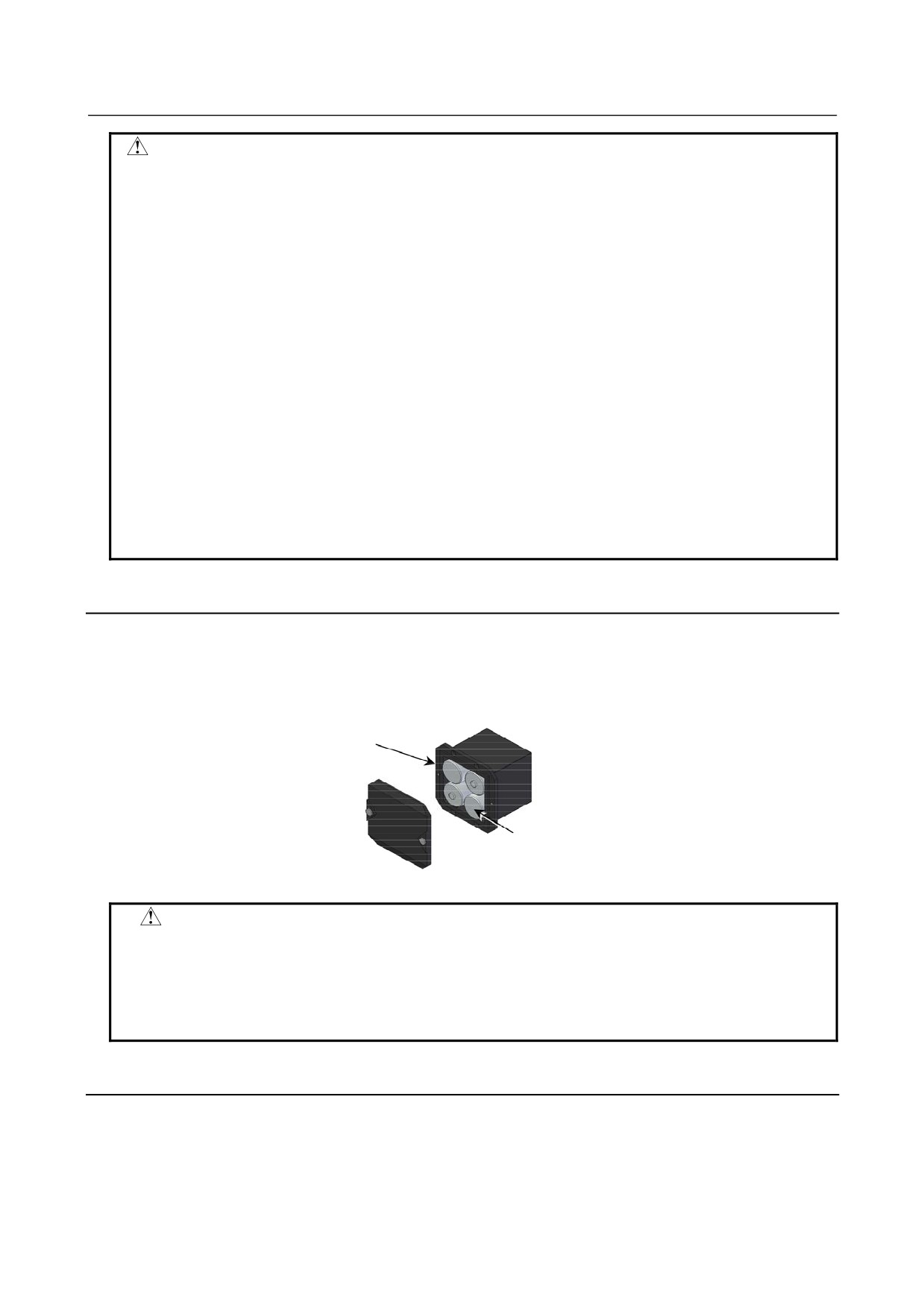
4.10.3 Replacing the Batteries in a Separate Battery Case
Use the following procedure to replace the batteries in the battery case.
<1> Loosen the screws on the battery case and detach the cover.
<2> Replace the batteries in the case (pay attention to the polarity).
<3> Attach the cover to the battery case.
Battery case (with a cover)
A06B-6050-K060
Batteries
Four A06B-6050-K061 batteries or
D-size alkaline dry cells
CAUTION
・ Four D-size alkaline dry cells (LR20) that are commercially available can be
used as batteries. A set of four A06B-6050-K061 batteries is optionally available
from FANUC.
・ Replace all the four batteries with new ones. If old and new batteries are mixed,
the absolute position information in the absolute Pulsecoders may be lost.
4.10.4 Replacing the Battery Built into the Servo Amplifier
Use the following procedure to replace the special lithium battery.
<1> Detach the battery cover.
<2> Replace the special lithium battery.
<3> Attach the battery cover.
- 180 -
4.MATTERS COMMON TO BOTH LCD-MOUNTED TYPE
B-64305EN/03
AND STAND-ALONE TYPE (HARDWARE)
CAUTION
・ Purchase the battery from FANUC because it is not commercially available. It is
therefore recommended that you have a backup battery.
・ When the built-in battery is used, do not connect BATL (B3) of connector
CXA2A/CXA2B. Also, do not connect two or more batteries to the same BATL
(B3) line. These connections are dangerous because battery output voltages
may be short-circuited, causing the batteries to overheat.
・ Install the battery in the servo amplifier in a direction that allows slack in the
cable. If the battery cable is under tension, a bad connection may occur.
・ If the +6 V pin and 0 V pin are short-circuited, the battery may overheat, blow
out, or catch fire, or the absolute position information in the absolute
Pulsecoders may be lost.
・ When inserting the connector, align it to the connector pins.
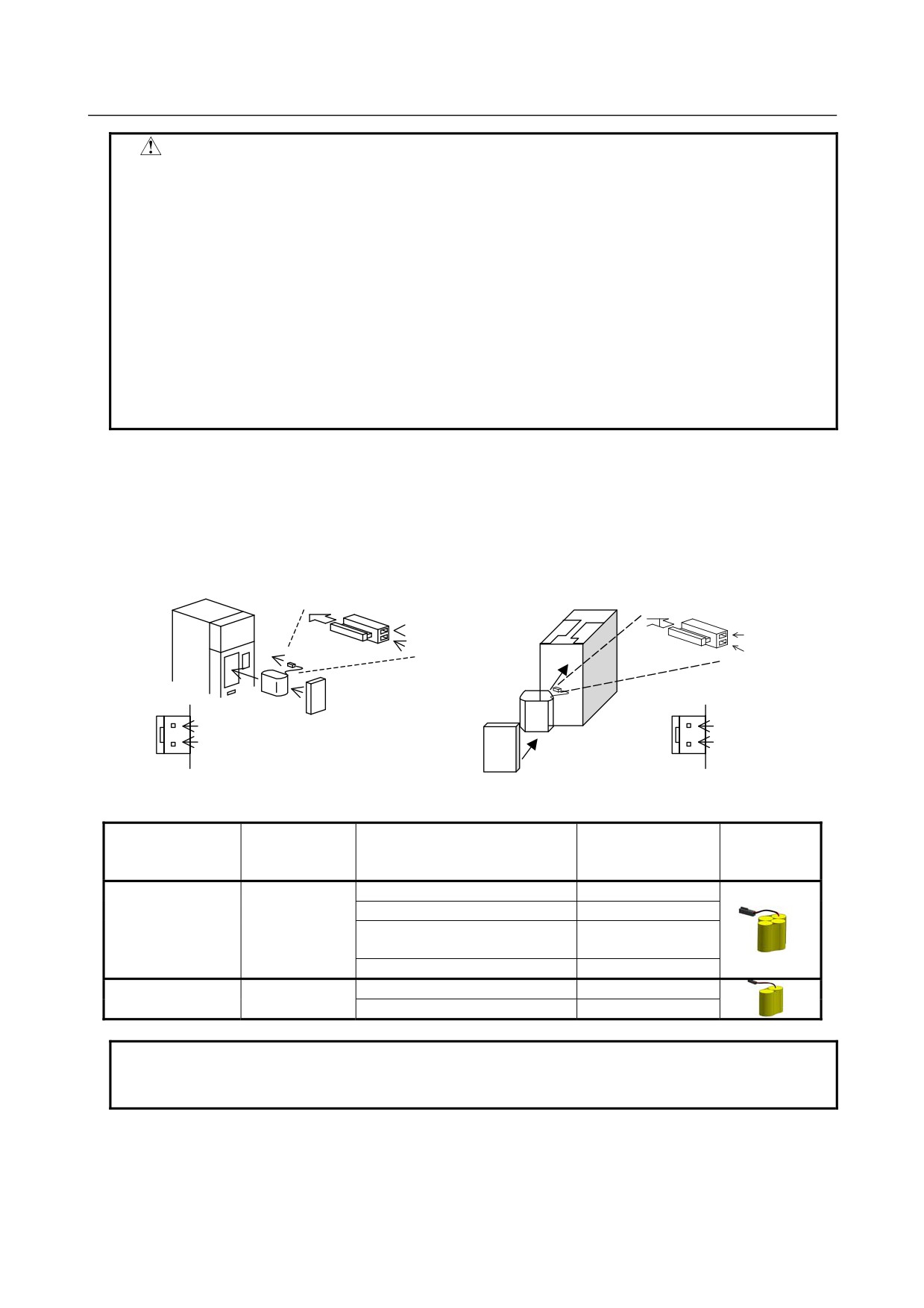
[Connecting the battery]
The battery for the βiSV4 and βiSV20 series amplifiers is mounted in the battery case on the underside of
each of the amplifiers.
The battery for the other βi series amplifiers and the αi series amplifiers is mounted at the front of each of
the amplifiers.
[αi series][βi series βi SV40, βi SV80, βi SVSP]
[βi series βi SV4, βi SV20]
Insertion direction
Cable side
Insertion direction
Cable side
Red: +6 V
Red: +6 V
Connector
Black: 0 V
Connector
Black: 0 V
CX5X
CX5X
Battery
+6 V
Battery case
+6 V
0 V
0 V
Battery
Battery case
[Battery sets and outlines]
Battery case
Battery ordering
Manufacturer
Applicable servo amplifier
ordering drawing
Outline
drawing number
model number
number
BR-2/3AGCT4A
αi series
60/90 mm width
A06B-6114-K505
(Panasonic)
αi series
150/300 mm width
A06B-6114-K506
A06B-6114-K504
βi series βi SV
(Note)
A06B-6114-K505
(two-axis model)
βi series βi SVSP
A06B-6114-K506
BR-AGCF2W
βi series βiSV4, βiSV20
A06B-6093-K002
A06B-6093-K001
(Panasonic)
βi series βiSV40, βiSV80
A06B-6093-K002
NOTE
When an old type BR-CCF2TH battery is used, order a battery case that
accommodates battery A06B-6114-K504.
Used batteries
Old batteries should be disposed as "INDUSTRIAL WASTES" according to the regulations of
the
country or autonomy where your machine has been installed.
- 181 -
4. MATTERS COMMON TO BOTH LCD-MOUNTED TYPE
AND STAND-ALONE TYPE (HARDWARE)
B-64305EN/03
4.11 CAUTIONS IN REPLACING PCB’S
This CNC supports the “FANUC Remote Option System.”
There are several cautions that should be observed in replacing printed circuit boards. Follow the
replacement procedure below.
PCB replacement procedure
1)
Optional parameters are stored in an option information file (with file name “OPRM INF”) in the
FROM module.
Before replacing a printed-circuit board, back up the optional information file as well as SRAM data
and user files as usual. If the optional information is corrupted during replacement, the backed-up
data will become necessary in recovery work.
2)
As usual, after replacing a printed-circuit board, restore the SRAM data and user files as required.
3)
If the FROM/SRAM module is replaced, it is necessary to restore the optional information file that
was held in the FROM module. Use the data backed up at step 1). Once restoration is finished,
alarm PS5523 "Option authentication wait state" will occur when the power is turned on. It is
necessary to access FANUC’s web site and perform optional parameter authentication work with the
"FANUC Remote Option System" within the period of validity (within 30 days since the occurrence
of the alarm).
(Within the period of validity, alarm PS5523 can be canceled by a reset.)
4)
Replacing a printed-circuit board may result in a change to the CNC ID number. Check it on the
CNC screen. If it is different from one described on the data sheet, correct the data sheet.
- 182 -
B-64305EN/03
5.INPUT AND OUTPUT OF DATA
5 INPUT AND OUTPUT OF DATA
Parameters, offset values, and other data can be backed up in external I/O devices. SRAM data can also
be backed up at a time. This backup data can be restored to set data again easily. It is recommended
that various types of data and SRAM data be backed up periodically in case data stored in the CNC is
destroyed due to an operation error or backup battery exhaustion.
This chapter explains how to input or output data, such as parameters, part programs, and tool offset
values, with external I/O devices such as floppy disk units.
This chapter also explains automatic data backup (optional function) that automatically backs up SRAM
data periodically.
5.1 SETTING PARAMETERS FOR INPUT/OUTPUT
183
5.2 INPUTTING/OUTPUTTING DATA
185
5.3 AUTOMATIC DATA BACKUP
189
SRAM data can be saved and restored at a time using the boot system. For details of the boot system,
see Appendix C, “BOOT SYSTEM,” and Appendix F, “MAINTENANCE OF OPEN CNC (BOOT-UP
AND IPL).”
For details of Inputting and Outputting Parameters of the I/O Link Option for the FANUC servo unit βi
series (I/O Link βi), see section 1.8.2. For details of PMC data Input/Output, see section 6.4.7.
5.1
SETTING PARAMETERS FOR INPUT/OUTPUT
Setting procedure of parameters
Parameter writing is enabled with following steps 1 to 3.
1
Set to MDI mode or emergency stop state.
2
Press function key
several times or press soft key
[SETTING] to display SETTING
(HANDY) screen.
3
Set the cursor to PARAMETER WRITE and, press
and
keys in this order. Here alarm
100 will be displayed.
4
Press function key
several times to display the following screen.
PARAMETER
(SETTING)
O1234 N12345
0000
SEQ
INI ISO TVC
0
0
0
0
0
0
0
0
0001
FCV
0
0
0
0
0
0
0
0
0012 RMV
MIR
X
0
0
0
0
0
0
0
0
Y
0
0
0
0
0
0
0
0
Z
0
0
0
0
0
0
0
0
B
0
0
0
0
0
0
0
0
0020 I/O CHANNEL
To make the cursor
display in bit unit,
S
0
T0000
press the cursor key
REF
****
***
***
10: 15: 30
or
[ PARAM][ DGNOS][
][SYSTEM][(OPRT)]
- 183 -
5.INPUT AND OUTPUT OF DATA
B-64305EN/03
5
Press soft key [(OPRT)] and the following operation menu is displayed.
<1> Soft key [NO. SRH] :
Searched by number.
Examination)
Parameter number → [NO. SRH].
<2> Soft key [ON : 1] :
Item with cursor position is set to 1 (bit parameter)
<3> Soft key [OFF : 0] :
Item with cursor position is set to 0 (bit parameter)
<4> Soft key [+INPUT] :
Input value is added to the value at cursor
<5> Soft key [INPUT] :
Input value is replaced with the value at cursor
<6> Soft key [F INPUT] :
Parameters are input from reader/puncher interface.
<7> Soft key [F OUTPUT] :
Parameters are output to reader/puncher interface.
6
After the parameters have been input, set PARAMETER WRITE on the SETTING screen to 0. Press
key to release alarm 100.
7
Convenient method
<1> To change parameters in bit unit, press cursor key
or
, then the cursor becomes
bit length and you can set parameters bit by bit (Bit parameter only).
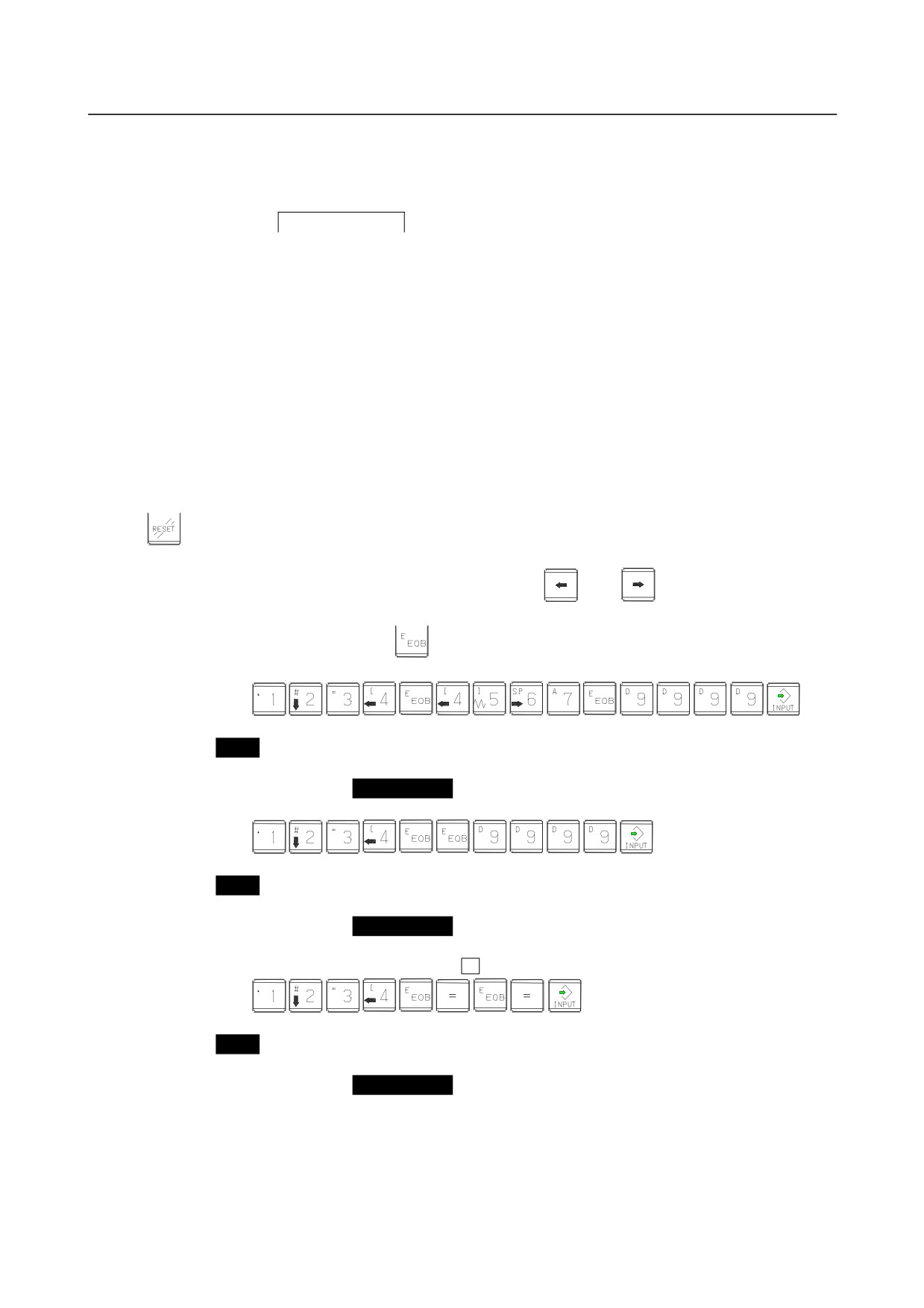
<2> To set data consecutively, use
key.
(Ex.1)
This key sequence sets data as follows:
0
1234
0
⇒
4567
0
9999
0
0
(Ex.2)
This key sequence sets data as follows:
0
1234
0
⇒
0
0
9999
0
0
<3> To set the same data sequentially, press
=
(Ex.1)
This key sequence sets data as follows:
0
1234
0
⇒
1234
0
1234
0
0
- 184 -
B-64305EN/03
5.INPUT AND OUTPUT OF DATA
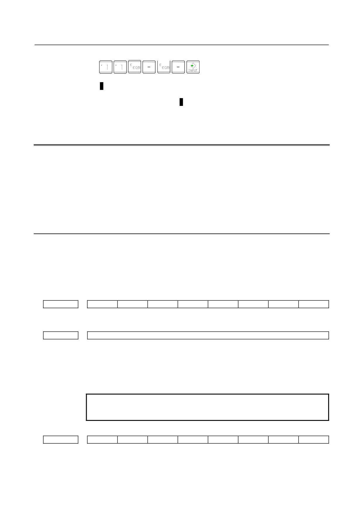
<4> Bit parameters can be set as follows:
(Ex.1)
This key sequence sets data as follows:
0 0 0 0 0 0 0 0
0 0 0 1 1 0 0 0
0 0 0 0 0 0 0 0
⇒
0 0 0 1 1 0 0 0
0 0 0 0 0 0 0 0
0 0 0 1 1 0 0 0
0 0 0 0 0 0 0 0
0 0 0 0 0 0 0 0
8
After the required parameters are set, set PARAMETER WRITE to 0.
5.2
INPUTTING/ OUTPUTTING DATA
The CNC memorized the following data.
Outputting the data I/O device while the CNC is running normally.
(1) CNC parameter (See Section 5.2.2)
(2) PMC parameter (See Section 6.4.7)
(3) Pitch error compensation amount (See Section 5.2.3)
(4) Custom macro variable values (See Section 5.2.4)
(5) Tool compensation amount
(See Section 5.2.5)
(6) Part program (machining program, custom macro program) (See Section 5.2.6)
5.2.1
Confirming the Parameters Required for Data Input/Output
Be sure that data output cannot be done in an alarm status.
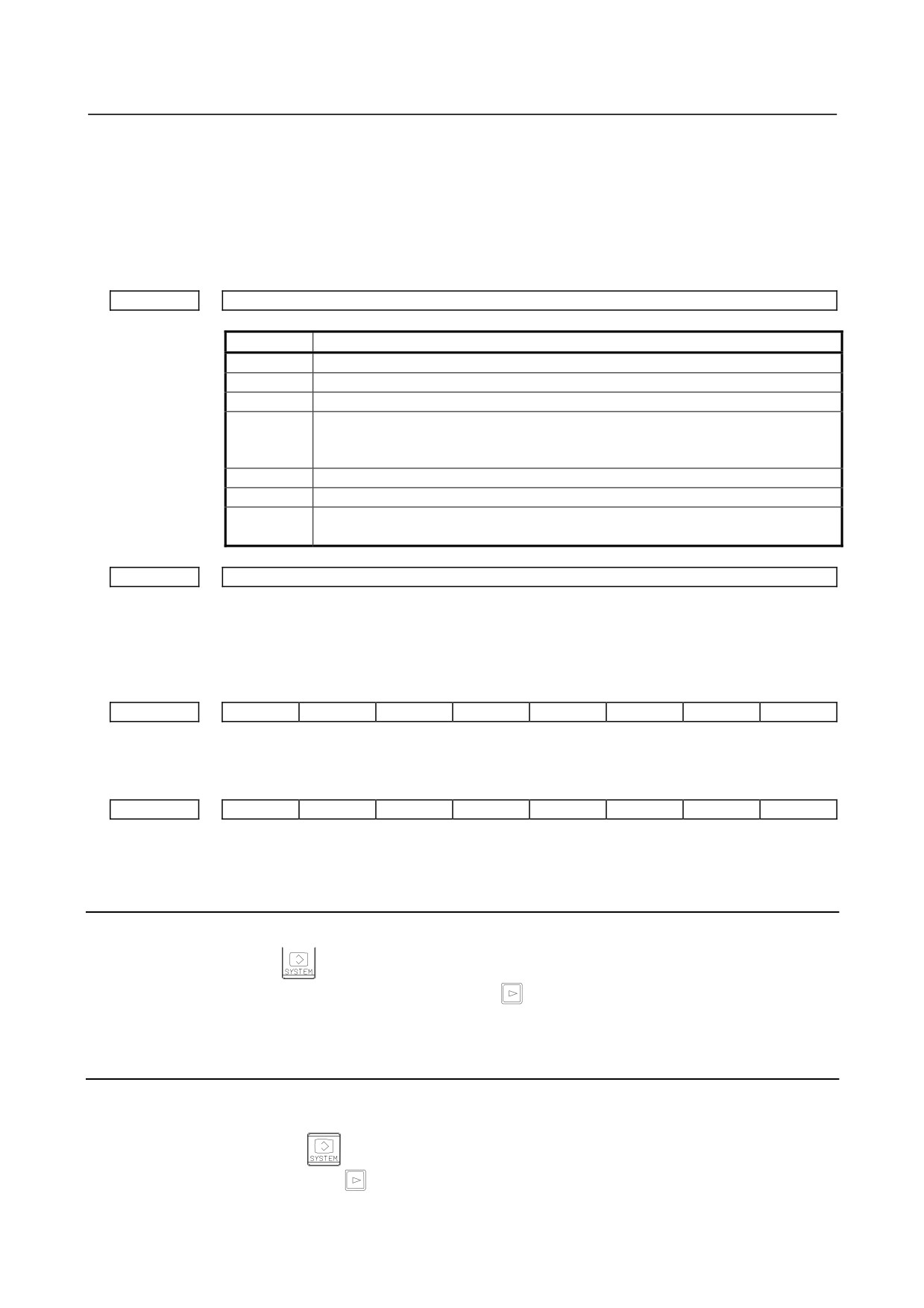
The following parameters are required for F INPUT and F OUTPUT.
In addition, (*) indicates the standard setting for input/output devices made by FANUC. Change these
settings according to the unit you actually use.
(Parameter can be changed in MDI mode or emergency stop status.)
#7
#6
#5
#4
#3
#2
#1
#0
0000
ISO
ISO
0: Output with EIA code
1: Output with ISO code (for RS-232-C serial port 1 or 2)
0020
Selection of I/O channel
(*)
0 : Channel 1 (RS-232-C serial port 1: JD36A of main board)
1 : Channel 1 (RS-232-C serial port 1: JD36A of main board)
2 : Channel 2 (RS-232-C serial port 2: JD36B of main board)
4 : Memory card interface
5 : Data Server interface
9: Embedded Ethernet interface
NOTE
In the operation examples in this chapter, data input/output is done
with an I/O device connected to JD36A.
(I/O channel = 0)
#7
#6
#5
#4
#3
#2
#1
#0
0101
NFD
ASI
SB2
NFD
0 : Feed is output when data is output.
1 : Feed is not output when data is output.
- 185 -
5.INPUT AND OUTPUT OF DATA
B-64305EN/03
ASI (*)
0 : EIA or ISO code is used for input/output data.
(input: automatic detection, output: setting of bit 1 (ISO) of parameter No.
0000)
1 : ASCII code is used.
(To use the ASCII code, set bit 1 (ISO) of parameter No. 0000 to 1. )
SB2
0 : No. of stop bits is 1.
(*)
1 : No. of stop bits is 2.
0102
Number specified for the input/output device
Set value
Input/output device
0
RS-232-C (Used control codes DC1 to DC4)
1
FANUC CASSETTE ADAPTOR 1 (FANUC CASSETTE B1/B2)
2
FANUC CASSETTE ADAPTOR 3 (FANUC CASSETTE F1)
FANUC PROGRAM FILE Mate, FANUC FA Card Adaptor
3
FANUC FLOPPY CASSETTE ADAPTOR, FANUC Handy File
FANUC SYSTEM P-MODEL H
4
RS-232-C (Not used control codes DC1 to DC4)
5
Portable tape reader
FANUC PPR
6
FANUC SYSTEM P-MODEL G, FANUC SYSTEM P-MODEL H
0103
Baud Rate
1:
50
7:
600
11:
9600
3:
110
8:
1200
12:
19200
[BPS]
4:
150
9:
2400
6:
300
(*)10: 4800
#7
#6
#5
#4
#3
#2
#1
#0
0139
ISO
ISO
0:
ASCII code input/output
1:
ISO code input/output (with memory card)
#7
#6
#5
#4
#3
#2
#1
#0
0908
ISO
ISO
0 :
ASCII code input/output
1 :
ISO code input/output (with Data Server)
5.2.2
Outputting CNC Parameters
1
Enter EDIT mode or the emergency stop condition.
2
Press function key
and soft key [PARAMETER] to select a parameter screen.
3
Press soft key [(OPRT)] and continuous menu key
4
Press soft keys [F OUTPUT] and [EXEC], and the parameters are started to be output.
5.2.3
Outputting Pitch Error Compensation Amount
If pitch error compensation is enabled, a pitch error compensation amount is output.
1
Select EDIT mode.
2
Press the function key
3
Press continuous menu key
several times, then press soft key [PITCH] to select the pitch error
compensation setting screen.
- 186 -
B-64305EN/03
5.INPUT AND OUTPUT OF DATA
4
Press soft key [(OPRT)] and continuous menu key
5
Press soft keys [F OUTPUT] and [EXEC], then pitch error compensation amount is started to be
output.
5.2.4
Outputting Custom Macro Variable Values
When custom macro function is valid, values of variable No. 500 and later are output.
1
Select EDIT mode.
2
Press the function key
3
Press continuous menu key
several times, then press soft key [MACRO] to select custom
macro variable screen.
4
Press soft key [(OPRT)] and then continuous menu key
5
Press soft keys [F OUTPUT] and [EXEC], then custom macro variable values are output.
5.2.5
Outputting Tool Compensation Amount
1
Select EDIT mode.
2
Press function key
and soft key [OFFSET] to display the tool compensation amount screen.
3
Press soft key [(OPRT)] and continuous menu key
4
Press soft keys [F OUTPUT] and [EXEC], and the tool compensation amount is started to be output.
5.2.6
Outputting Part Program
1
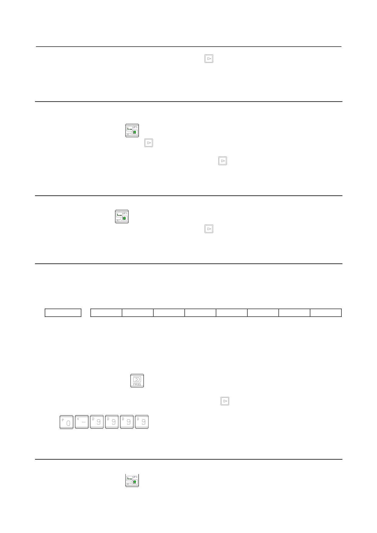
Confirm the following parameters. If their setting does not match those indicated with the asterisk,
select the MDI mode and re-set them and keep them re-set only while this work is being done.
However, if you changed the parameter setting, restore the original value after finishing this work.
#7
#6
#5
#4
#3
#2
#1
#0
3202
NE9
NE8
NE9 (*)
0: Programs of 9000s are edited.
1: Programs of 9000s can be protected.
(Protected programs are not output.)
NE8 (*)
0: Programs of 8000s are edited.
1: Programs of 8000s can be protected.
(Protected programs are not output.)
2
Select EDIT mode.
3
Press the function key
and then the soft key [PROGRM] to select the program content
display screen.
4
Press soft key [(OPRT)] and press continuous menu key
5
Input a program number to be output. To output all programs input as:
6
Press soft keys [F OUTPUT] and [EXEC], then program output is started.
5.2.7
Inputting CNC Parameters
1
Set to the emergency stop state.
2
Press the function key
and then the soft key [SETTING] to select the setting screen.
Confirm “PARAMETER WRITE=1” on the setting screen.
- 187 -

5.INPUT AND OUTPUT OF DATA
B-64305EN/03
3
Press function key
and soft key [PARAMETER] to select the parameter screen.
4
Press soft key [(OPRT)] and continuous menu key
5
Press soft keys [F INPUT] and [EXEC]. Then input of parameters are started.
6
Upon completion of parameter input, turn off the power then turn on the power again.
5.2.8
Inputting Pitch Error Compensation Amount
If pitch error compensation is enabled, a pitch error compensation amount is input.
1
Select EDIT mode.
2
Confirm that PARAMETER WRITE=1 on the setting screen.
3
Press the function key
4
Press continuous menu key
several times, then press soft key [PITCH] to select the pitch error
compensation setting screen.
5
Press soft key [(OPRT)] and continuous menu key
6
Press soft keys [F INPUT] and [EXEC], then pitch error compensation amount is started to be input.
7
After a pitch error compensation amount is input, display the setting screen and reset
“PARAMETER WRITE” to “0” on the setting screen.
5.2.9
Inputting Custom Macro Variable Values
When custom macro function is valid, input the variable values.
1
Select EDIT mode.
2
Turn off the program protect (KEY2=1).
3
Press the function key
4
Press continuous menu key
several times, then press soft key [MACRO] to select the custom
macro variable screen.
5
Press soft key [(OPRT)] and continuous menu key
6
Press soft keys [F INPUT] and [EXEC], then custom macro variable values is started to be input.
5.2.10 Inputting Tool Compensation Amount
1
Select EDIT mode.
2
Turn off the program protect (KEY=1).
3
Press the function key
4
Press soft key [OFFSET] to display the tool compensation amount display screen.
5
Press soft key [(OPRT)] and continuous menu key
6
Press soft keys [F INPUT] and [EXEC], then tool compensation amount is started to be input.
5.2.11 Inputting Part Programs
1
Confirm the following parameters. If their setting does not match those indicated with the asterisk,
select the MDI mode and re-set them and keep them re-set only while this work is being done.
However, if you changed the parameter setting, restore the original value after finishing this work.
#7
#6
#5
#4
#3
#2
#1
#0
3201
NPE
RAL
NPE When programs are registered in part program storage area, M02,M30 and M99 are:
0: Regarded as the end of program.
- 188 -
B-64305EN/03
5.INPUT AND OUTPUT OF DATA
(*)
1: Not regarded as the end of program.
RAL When programs are registered:
(*)
0: All programs are registered.
1: Only one program is registered.
#7
#6
#5
#4
#3
#2
#1
#0
3202
NE9
NE8
NE9 (*)
0: Programs of 9000s can be edited.
1: Programs of 9000s are protected.
NE8 (*)
0: Programs of 8000s can be edited.
1: Programs of 8000s are protected.
2
Select EDIT mode.
3
Turn off the program protect (KEY3=1).
4
Press the function key
and then the soft key [PROGRM] to select the program content
display screen.
5
Press soft key [(OPRT)] and press continuous menu key
6
Press soft keys [F INPUT] and [EXEC], then program input is started.
5.3
AUTOMATIC DATA BACKUP
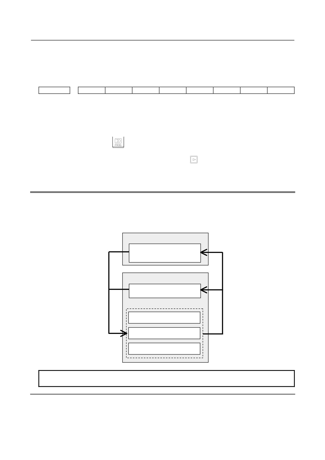
It is possible to back up data held in the CNC’s FROM/SRAM by storing it automatically in the FROM,
which requires no battery and to restore the baked-up data as required. If data is lost from the CNC due
to unforeseen circumstances, this function can be used to restore the data easily.
Also, it is possible to hold three occurrences of backup data. With this function, the CNC data can be
quickly switched to a post-machine adjustment state or an arbitrary backup state.
SRAM (requires batteries)
Backup
All types of data, such as
parameters and offset data, in
SRAM
FROM (requires no battery)
NC programs and directory
information
Backup data 1
Backup data 2
Restore
Backup data 3
NOTE
Automatic data backup function is optional function.
Explanation
- Data to be backed up
Data in the CNC is backed up by storing it in the FROM, which requires no battery.
• NC programs held in the FROM (which requires no battery)
- 189 -
5.INPUT AND OUTPUT OF DATA
B-64305EN/03
• Various types of data, such as parameters and offset values, held in the SRAM (which requires
batteries)
Setting bit 2 (AAP) of parameter No.10340 to 1 enables NC programs in the FROM to be backed up.
Set this parameter only when necessary, because the required backup time and data storage size vary
depending on the size of the programs.
Also, it is possible to hold three occurrences of backup data.
- Backup modes
The following three backup modes are available.
1.
Automatic backup occurring every time the power is turned on
2.
Automatic backup occurring at intervals of a specified number of days when the power is turned on
3.
Backup started manually at an emergency stop
- Automatic backup occurring every time the power is turned on
Data in the CNC can be backed up automatically when the power is turned on.
This mode can be used by:
• Setting bit 0 (ABP) of parameter No. 10340 to 1
• Setting bit 2 (AAP) of parameter No. 10340 to 1 if also NC programs in the FROM must be backed
up
- Automatic backup occurring at intervals of a specified number of days when the
power is turned on
Data in the CNC can be backed up automatically when the power is turned on for the first time in a
specified number of days since the previous backup.
This mode can be used by:
• Selecting the first backup mode (automatic backup occurring every time the power is turned on)
• Setting parameter No. 10341 with a number of days at intervals of which automatic backup is to be
made cyclically
- Backup started manually at an emergency stop
Data in the CNC can be backed up by starting an appropriate procedure manually in an emergency stop
state. This mode makes it possible to back up data without turning off the power for the CNC at an
arbitrary timing, such as when machining has been set up or before a holiday.
If you want to back up NC programs in the FROM, set bit 2 (AAP) of parameter No. 10340 to 1 before
backup operation.
[Backup procedure]
1.
Put the machine in an emergency stop state.
2.
Set bit 7 (EEB) of parameter No. 10340 to 1 to start backup. This parameter becomes 0 just after
the backup sequence has started.
3.
The execution status of backup can be checked with No. 1016 on the diagnosis screen described
later.
NOTE
It takes time since the beginning of backup till the end of backup. So, if data
being backed up is updated, it is likely that a mismatch may occur between the
original data and backup data. When updating data in the CNC at an
emergency stop, watch the automatic data backup in-progress signal ATBK and
perform appropriate processing.
- Backup execution status
In the backup modes used at power-on time, 10 dots “.” are used to indicate the execution status of
backup. For example, the completion of backup is indicated with:
“AUTO BACKUP : ……….END
- 190 -

B-64305EN/03
5.INPUT AND OUTPUT OF DATA
The diagnosis screen can also be used to check the execution status of backup as follows:
• No.1016#0 (AEX): Backup in progress
• No.1016#6 (ACM): Backup completed
• No.1016#7 (ANG): Error during backup
• No.1016#1 (DT1), #2 (DT2), #3 (DT3): Numbers of updated backup data items
- Write-protected backup data
Factory-set or post-adjustment machine status data can be held as write-protected backup data. The first
piece (data 1) of backup data is handled as write-protected backup data.
This function is enabled by:
• Setting bit 1 (ABI) of parameter No. 10340 to 1
• Setting bit 2 (AAP) of parameter No. 10340 to 1 if also NC programs in the FROM must be backed
up
[Procedure for creating write-protected data]
1.
Set bit 6 (EIB) of parameter No. 10340 to 1.
2.
Turn the power for the CNC off and on again. When the power is turned on, the first piece of
backup data is updated automatically, and bit 6 (EIB) of parameter No. 10340 becomes 0.
Then, the first backup data is handled as write-protected data until the same operation is performed again.
The second and third pieces of backup data are updated each time another type of backup (automatic
backup occurring every time the power is turned on, automatic backup occurring at intervals of a
specified number of days when the power is turned on, or backup started manually at an emergency stop)
is made.
- Parity check
A parity check is made at backup. If a parity error is detected, the backup is not completed.
- Restoring backed-up data
With the BOOT SYSTEM, executing the following procedure can restore backed-up data from FROM.
1.
From the BOOT’s TOP menu, select “7. SRAM DATA UTILITY”. The following menu appears.
Select ”3”.
SRAM DATA UTILITY
1.SRAM BACKUP
( CNC -> MEMORY CARD )
2.SRAM RESTORE ( MEMORY CARD -> CNC )
3.AUTO BKUP RESTORE ( FROM -> CNC )
4. END
2.
From the menu below, select data and run restore.
AUTO BACKUP DATA RESTORE
1. BACKUP DATA1 yyyy/mm/dd **:**:**
2. BACKUP DATA2 yyyy/mm/dd **:**:**
3. BACKUP DATA3 yyyy/mm/dd **:**:**
4
END
3.
Exit BOOT.
Signal
Automatic data backup in-progress signal ATBK<F0520.0>
[Classification] Output signal
[Function] This signal is "1" during automatic data backup. When updating data in the CNC at an
emergency stop, perform appropriate processing according to the state of this signal.
- 191 -

5.INPUT AND OUTPUT OF DATA
B-64305EN/03
Signal address
#7
#6
#5
#4
#3
#2
#1
#0
F0520
ATBK
Parameter
#7
#6
#5
#4
#3
#2
#1
#0
10340
EEB
EIB
AAP
ABI
ABP
[Input type] Parameter input
[Data type] System-common type
# 0
ABP Automatic data backup at power-on is:
0: Disabled.
1: Enabled.
# 1
ABI Overwrite-protected backup data is:
0: Regarded as invalid.
1: Regarded as valid.
# 2
AAP Backup of NC programs in FROM is:
0: Disabled.
1: Enabled.
# 6
EIB When the CNC is turned on next, overwrite-protected backup data is:
0: Not updated.
1: Updated.
NOTE
This parameter is valid when bit 1 (ABI) of parameter No. 10340 is
set to 1.
# 7
EEB When an emergency stop occurs, a backup operation is:
0: Not performed.
1: Performed.
10341
Interval at which automatic data backup is performed periodically
[Input type] Parameter input
[Data type] Word
[Unit of data] No unit
[Valid data range] 0 to 365
When automatic data backup is performed periodically, this parameter sets the interval as
the number of days. When the power is turned on after a set number of days has passed
from the date of the previous backup, a backup operation is performed. If 0 is set in this
parameter, this function is disabled.
- 192 -

B-64305EN/03
5.INPUT AND OUTPUT OF DATA
Diagnosis display
This function enables the status of backup execution to be checked.
#7
#6
#5
#4
#3
#2
#1
#0
1016
ANG
ACM
DT3
DT2
DT1
AEX
#0 AEX Indicates whether automatic data backup is being executed, as follows:
0: Not being executed
1: Being executed
#1 DT1 Indicates whether data 1 has been updated in the previous backup, as follows:
0: Not updated
1: Updated
#2 DT2 Indicates whether data 2 has been updated in the previous backup, as follows:
0: Not updated
1: Updated
#3 DT3 Indicates whether data 3 has been updated in the previous backup, as follows:
0: Not updated
1: Updated
#6 ACM Indicates whether automatic data backup has been executed, as follows:
0: Not executed
1: Executed
#7 ANG Indicates whether an error has occurred in automatic data backup, as follows:
0: Not occurred
1: Occurred
Caution
CAUTION
1 Do not turn off the power for the NC during backup or restoration.
2 If backed-up data is restored, parameters submitted to automatic backup are
returned to the state in which they were when backed up. Change them as
required.
- 193 -