FANUC Series 0i-MODEL D, FANUC Series 0i Mate-MODEL D. MAINTENANCE MANUAL - page 5
3.STAND-ALONE TYPE CNC SERIES HARDWARE
B-64305EN/03
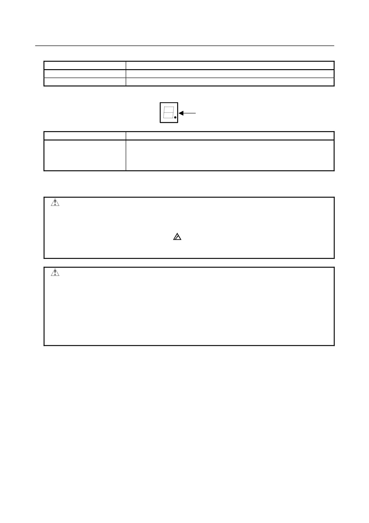
(2) Ethernet status LED
Alarm LED
Meaning
LINK (green)
Turned on when a connection is made with the hub correctly
COM (yellow)
Turned on when data is transferred
(3)
7-segment LED
Dot
Alarm LED
Meaning
Dot
Turned on when the display unit is not connected to connector COP21A.
If this LED is turned on when the display unit is connected, it is probable that the
optical cable is broken, the display unit is not powered on, or the display unit is
faulty.
See Appendix E “LED Display” for others.
・Replacing the main board
WARNING
Only those personnel who have received approved safety and maintenance
training may perform this replacement work.
When opening the cabinet and replacing the card PCB, be careful not to touch
the high-voltage circuits (marked
and fitted with an insulating cover).
Touching the uncovered high-voltage circuits presents an extremely dangerous
electric shock hazard.
CAUTION
Before replacing a printed circuit board, be sure to read Section 4.11,
“CAUTIONS IN REPLACING PCB’S,” to confirm the procedure.
Before starting replacement work, back up the SRAM data of the CNC.
Otherwise, the SRAM data may be lost during replacement work. See Section
3.9, “MAINTENANCE OF STAND-ALONE TYPE UNIT”, Chapter 5, “INPUT AND
OUTPUT OF DATA” or Appendix F, “MAINTENANCE OF OPEN CNC
(BOOT-UP AND IPL)” for explanations about how to save the contents of the
SRAM memory.
Demounting procedure
(1) The structure is designed so that the main board is fastened on the control unit with the fan unit.
For this reason, when the fan unit is mounted on the control unit, the main board cannot be
demounted.
Be sure to demount and mount the main board when the fan unit is detached. For the method of
detaching the fan unit, refer to Section 3.8, “REPLACING A FAN UNIT.”
(2) Disconnect the cables other than the battery cable.
(The battery is mounted on the face plate of the
main board, so the cable is not required to be disconnected.)
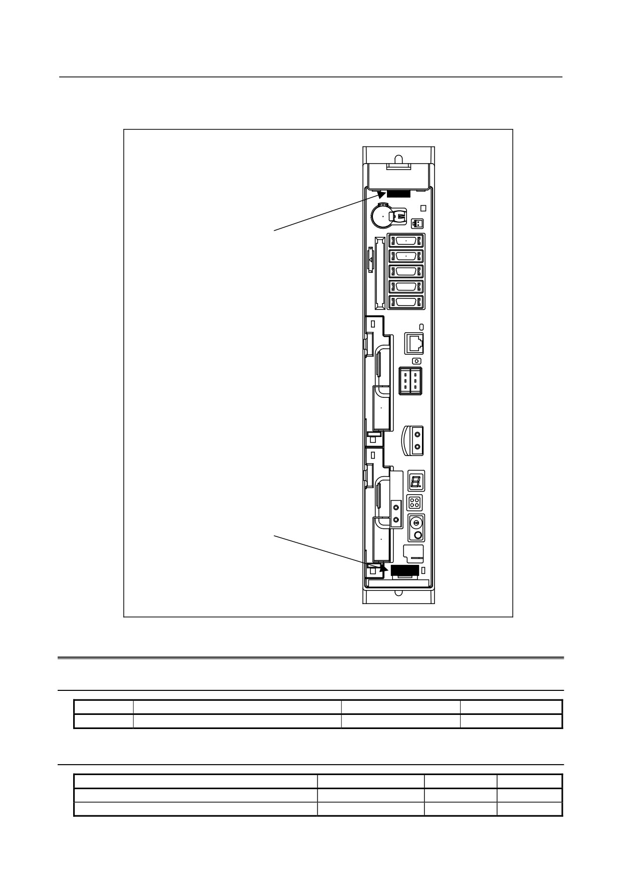
(3) Pinch handles A and B for extraction.
(4) While pushing the hook of handle A down and the hook of handle B up, extract the printed circuit
board.
Mounting procedure
(1) Pinch handles A and B for extraction, then insert the board into the control unit slowly until the
board is engaged into the connector on the back panel. Confirm that the hook of each of handles A
and B is engaged with the case.
(2) Connect the disconnected cables again correctly.
- 104 -
B-64305EN/03
3.STAND-ALONE TYPE CNC SERIES HARDWARE
(3) Attach the fan unit. The fan unit cannot be attached if the main board is not engaged on the back
panel firmly.
Handle A
With a hook on the top
Handle B
With a hook on the bottom
3.5
LIST OF UNITS AND PRINTED CIRCUIT BOARDS
3.5.1
List of Basic Units
Model
Item
Ordering code
Remarks
0i
Basic unit with 2 slots
A02B-0319-B802
3.5.2
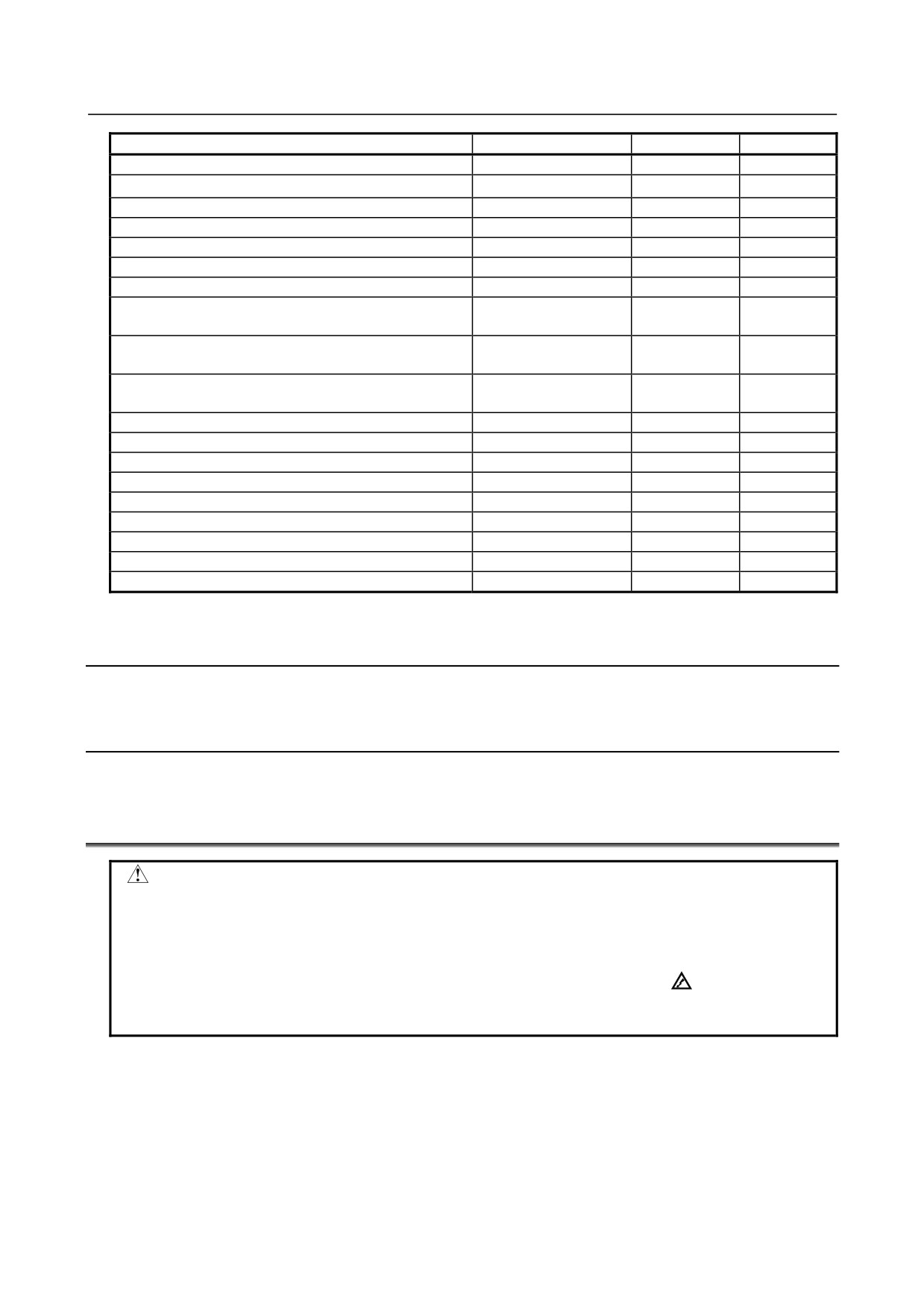
List of Printed Circuit Boards
Item
Ordering code
ID
Remarks
Main board A0
A16B-3200-0700
00448
Main board A1
A16B-3200-0701
00449
- 105 -
3.STAND-ALONE TYPE CNC SERIES HARDWARE
B-64305EN/03
Item
Ordering code
ID
Remarks
Main board A2
A16B-3200-0702
0044A
Main board A3
A16B-3200-0703
0044B
Axis card A1
A20B-3300-0635
00146
Axis card A2
A20B-3300-0638
0014B
Axis card A3
A20B-3300-0637
0014A
Axis card B2
A20B-3300-0632
0014D
Axis card B3
A20B-3300-0631
0014E
FROM/SRAM module A1
A20B-3900-0242
FROM: E3
(FROM 64MB, SRAM 1MB)
SRAM: 03
FROM/SRAM module B1
A20B-3900-0240
FROM: E4
(FROM 128MB, SRAM 1MB)
SRAM: 03
FROM/SRAM module B2
A20B-3900-0241
FROM: E4
(FROM 128MB, SRAM 2MB)
SRAM: 04
Fast Ethernet board
A20B-8101-0030
00701
PROFIBUS-DP master board
A20B-8101-0050
00704
PROFIBUS-DP slave board
A20B-8101-0100
00705
FL-net board
A20B-8101-0031
00702
DeviceNet master board
A20B-8101-0220
00706
DeviceNet slave board
A20B-8101-0330
00708
Backpanel (2 slots)
A20B-2003-0580
01
Fan connection board
A20B-9002-0350
-
Power supply
A20B-8101-0011
-
* See Chapter 4 for a optional board.
3.5.3
I/O
The same I/O components as for the LCD-mounted type are available. See Subsection 2.5.5.
3.5.4
Other Units
The same units as for the LCD-mounted type are available. See Subsection 2.5.5.
3.6
REPLACING THE FUSE OF THE CONTROL UNIT
WARNING
Before starting the replacement of a fuse, remove the cause of the fuse
burn-out.
Accordingly, the replacement should be performed by a person fully trained in
maintenance and safety. If the cabinet is opened to replace the fuse, take
extreme care not to touch any high-voltage area (marked with
and covered
by a shock prevention cover). If the area is uncovered, direct contact with this
area will result in an electric shock.
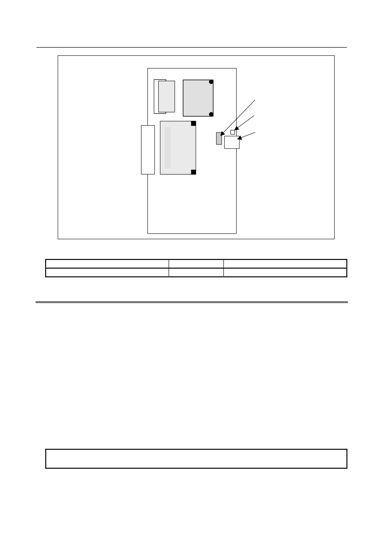
・Mounting position of the fuse of the control unit
The fuse of the control unit is mounted on the main board.
- 106 -
B-64305EN/03
3.STAND-ALONE TYPE CNC SERIES HARDWARE
Main board
Fuse
Fuse alarm LED
24V connector
CPD19A
CPD19B
・Ordering code of the fuse
Ordering code
Rating
Individual information
A02B-0319-K100
5A
A60L-0001-0046#5.0
3.7
REPLACING THE BATTERY
Offset data, and system parameters are stored in SRAM in the control unit. The power to the SRAM is
backed up by a lithium battery mounted on the front panel of the control unit. The above data is not lost
even when the main battery goes dead. The backup battery is mounted on the control unit at shipping.
This battery can maintain the contents of memory for about a year.
When the voltage of the battery becomes low, alarm message "BAT" blinks on the display and the battery
alarm signal is output to the PMC. When this alarm is displayed, replace the battery as soon as possible.
In general, the battery can be replaced within one or two weeks, however, this depends on the system
configuration.
If the voltage of the battery becomes any lower, memory can no longer be backed up. Turning on the
power to the control unit in this state causes system alarm to occur because the contents of memory are
lost. Clear the entire memory and reenter data after replacing the battery.
The following two kinds of batteries can be used.
• Lithium battery built into the CNC control unit.
• Two alkaline dry cells (size D) in the external battery case.
NOTE
A lithium battery is installed as standard at the factory.
- 107 -
3.STAND-ALONE TYPE CNC SERIES HARDWARE
B-64305EN/03
When using a lithium battery
-
Replacement procedure
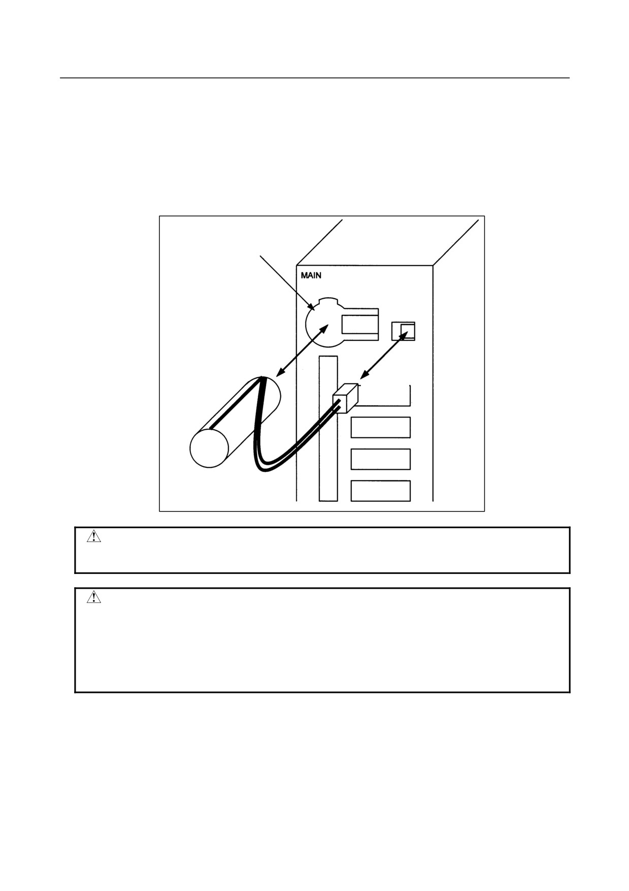
If a lithium battery is used, have A02B-0200-K102 (FANUC internal code: A98L-0031-0012) handy.
1
Turn the CNC on. About 30 seconds later, turn the CNC off.
2
Remove the battery from the top area of the CNC unit.
Disconnect the connector first. Then, remove the battery from the battery case. The connector is
not latched. Simply pulling the cable detaches the connector.
The battery case is provided in the top area of the face plate of the main board.
3
Replace the battery, then connect the connector.
Battery case
Lithium battery
A02B-0200-K102
Connector
WARNING
The incorrect mounting of the battery may cause an explosion. Avoid using any
battery other than the one specified here (A02B-0200-K102).
CAUTION
Complete steps 1 to 3 within 30 minutes.
If the battery is left removed for a long time, the SRAM would lose the contents.
If there is a danger that the replacement cannot be completed within 30 minutes,
save the whole contents of the SRAM to a memory card. The contents of the
memory can be easily restored with the memory card in case the memory loses
the contents.
Discard the dead battery, observing appropriate municipal rules and regulations. When discarding the
battery, insulate the terminal with a tape so that no short-circuit would occur.
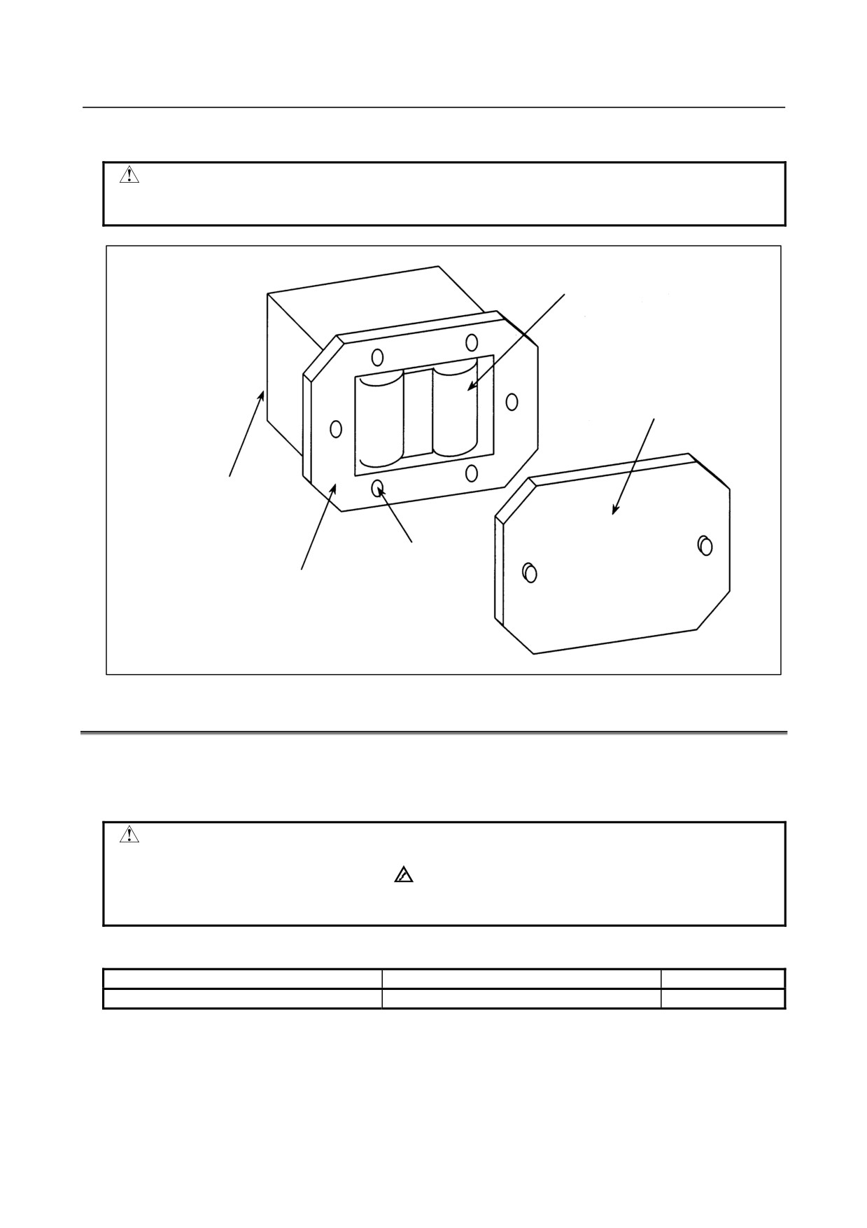
When using commercial D-size alkaline dry cells
-
Replacing the battery
1
Have commercial D-size alkaline dry cells handy.
2
Turn the CNC on.
3
Remove the lid from the battery case.
4
Replace the old dry cells with new ones. Mount the dry cells in a correct orientation.
- 108 -
B-64305EN/03
3.STAND-ALONE TYPE CNC SERIES HARDWARE
5
Replace the lid on the battery case.
CAUTION
In the power-off state, the battery should be replaced as in the case of the
lithium battery, which is descried above.
2 dry cells
Lid
Connection terminal
on the back
4 mounting holes
Case
3.8
REPLACING A FAN UNIT
When a reduction in the speed of the fan motor is detected, the FAN warning message blinks on the LCD
screen. If a fault such as the stoppage of the fan motor is detected, an overheat alarm is also issued.
When the FAN warning message is displayed, replace the fan unit as soon as possible.
WARNING
If the cabinet is opened to replace a fan unit, take extreme care not to touch any
high-voltage area (marked with
and covered by a shock prevention cover).
If the area is uncovered, direct contact with this area will result in an electric
shock.
・ Ordering code of fan units
Ordering code
Quantity
For 2-slot rack
A02B-0303-C101
1
-
Replacing a fan unit
Detaching a fan unit
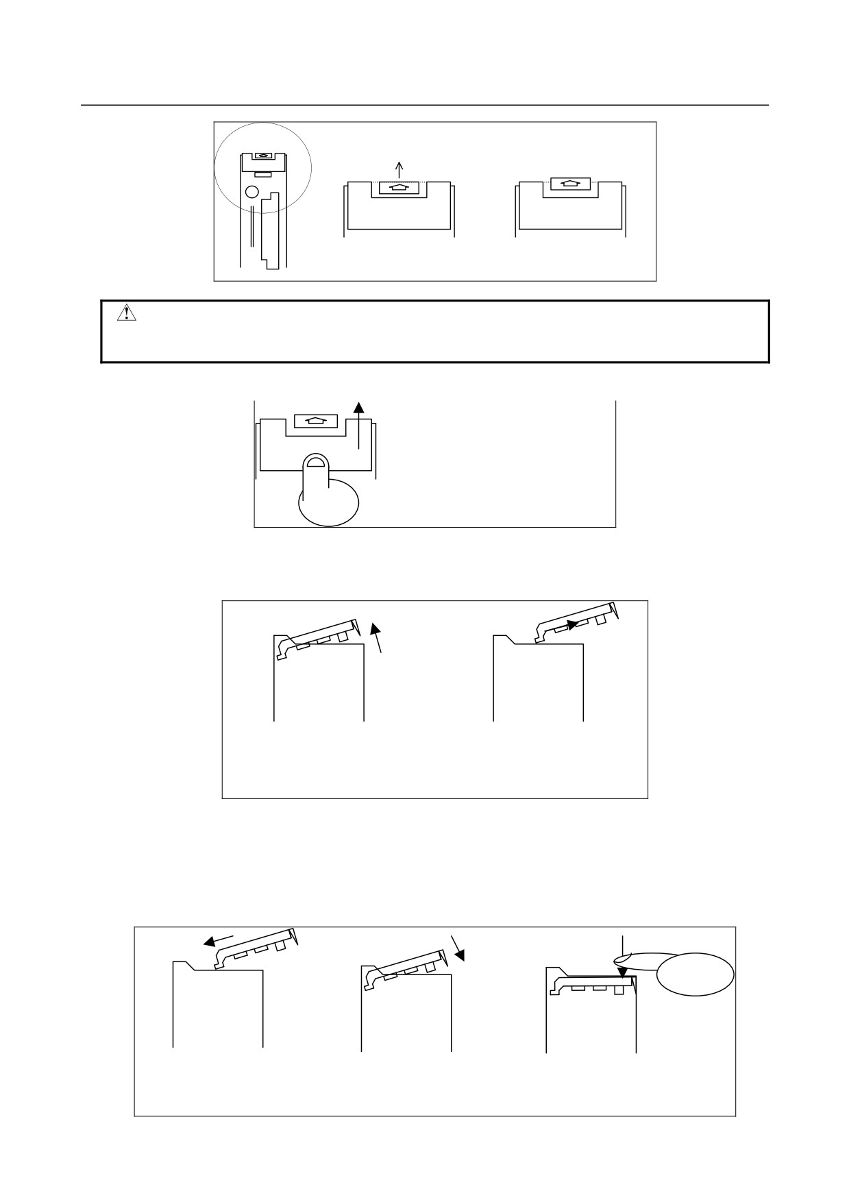
<1> When replacing the fan motor, be sure to turn off the power to the machine (CNC).
<2> Push up the latch at the top of the unit until the latch is disengaged.
- 109 -
3.STAND-ALONE TYPE CNC SERIES HARDWARE
B-64305EN/03
Push up the latch.
Latched
Unlatched
CAUTION
Just disengage the latch. Do not push up the latch after the latch is
disengaged. If you continue pushing up the latch forcibly, the latch can break.
<3> Place a finger at the bottom of the front of the fan unit then push up the fan unit.
Push up the fan unit.
<4> Push up the fan unit until the fan unit is slanted by about 30 degrees.
<5> Pull out the fan unit toward you in the slanted direction.
<4> Push up the fan unit until
<5> Pull out the fan unit toward
it is slanted by about 30
you in the slanted direction.
degrees.
Attaching a fan unit
<1> Insert a fan unit deeply into the main unit at a slanted angle of about 30 degrees until the fan unit
touches the wall of the main unit.
<2> Lower the fan unit slowly on the main unit.
<3> Push down the fan unit on the near side to couple the fan unit with the top of the main unit.
<1> Insert the fan unit at
<2> Lower the fan unit.
<3> Push down the fan unit to
an angle of about
couple it with the main
30 degrees.
unit.
- 110 -
B-64305EN/03
3.STAND-ALONE TYPE CNC SERIES HARDWARE
CAUTION
The fan unit and main unit are coupled directly with each other by a connector.
The coupling section of the connector can break if the units are coupled
incorrectly.
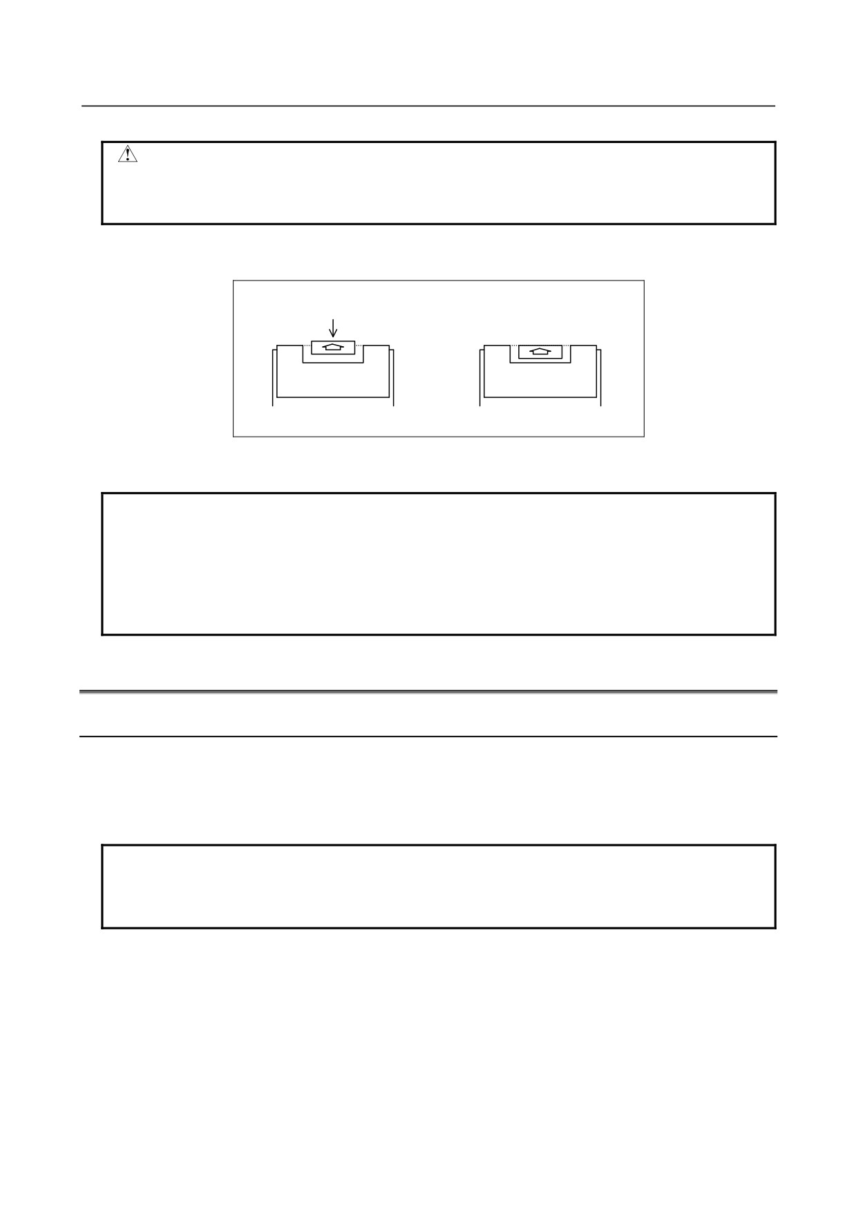
<4> Push down the latch at the top of the fan unit for latching.
Push down the latch.
Unlatched
Latched
<5> Turn on the power, then check that no fan alarm is issued and that both fans are rotating.
NOTE
1 If the power is turned on when the fan unit and the main unit are not coupled
correctly, the fans do not rotate or a fan alarm is issued even through the fans
are rotating.
2 When a large amount of force is required to couple the fan unit with the main
unit, check if pins of the connector of the main board are bent and if the main
board is inserted correctly.
3.9
MAINTENANCE OF STAND-ALONE TYPE UNIT
3.9.1
Overview
Overview
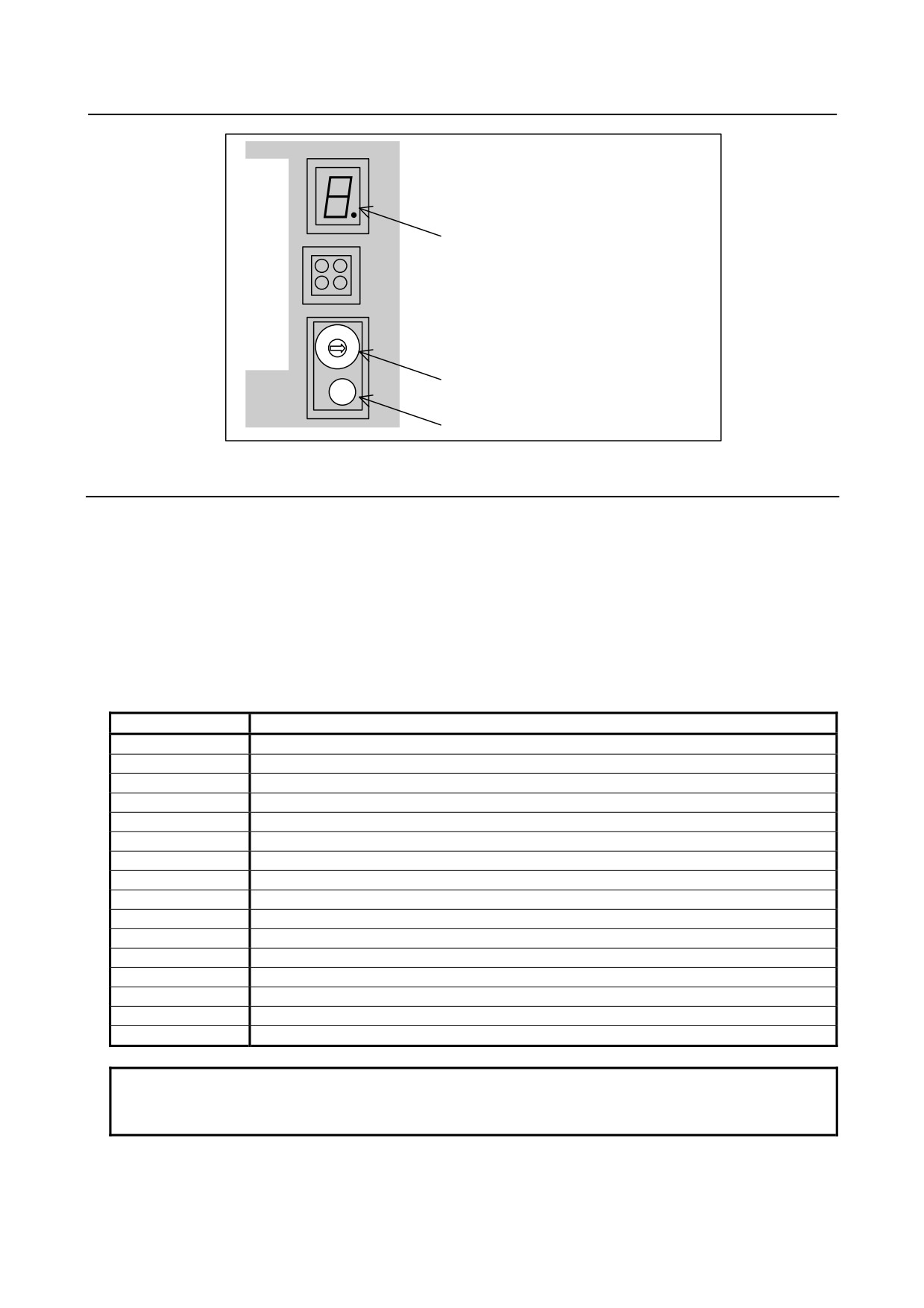
The FANUC Series 0i-D of stand-alone type has a 7-segmentL ED, rotary switch, and push switch.
When there is a display unit (PANEL i or personal computer) cannot be used due to a malfunction,
battery backed-up data can be saved or restored if the rotary switch and push switch are operated.
NOTE
When the display unit (PANEL i or personal computer) is available, perform
maintenance operation described in Appendix F, “MAINTENANCE OF OPEN
CNC (BOOT-UP AND IPL).”
Layout of the 7-segment LED and switches
The 7-segment LED, the rotary switch, and the push switch are located as shown in the following photo:
- 111 -
3.STAND-ALONE TYPE CNC SERIES HARDWARE
B-64305EN/03
7-segment LED (STATUS)
Rotary switch (MTSW)
Push switch (PSW)
3.9.2
Operation
Operation before power-on
Before turning on the power, select a function number by using the rotary switch. When the power is
turned on after the selection with the rotary switch, the number corresponding to the selected function
number is indicated on the LED. The indication blinks at intervals of about one second.
Function number
Each function is assigned a number. This number is called a function number hereinafter in this manual.
The function numbers that can be selected with the rotary switch are listed below. Do not set the reserved
function numbers.
Function number
Explanation
0
Normal state.
1
Reserved
2
Reserved
3
Reserved
4
Reserved
5
Clears all data in memory.
6
Reserved
7
Reserved
8
Saves battery backed-up main board data in a memory card at a time.
9
Reserved
A
Restores battery backed-up main board data from a memory card at a time.
B
Reserved
C
Reserved
D
Reserved
E
Reserved
F
Performs maintenance work.
NOTE
See Appendix F, “MAINTENANCE OF OPEN CNC (BOOT-UP AND IPL)” for the
function number F.
- 112 -

B-64305EN/03
3.STAND-ALONE TYPE CNC SERIES HARDWARE
3.9.3
Operation of Each Function
Function number 5
This function clears all the battery backed-up SRAM data.
WARNING
1 This operation enables the CNC system to start up solely (initial state).
Accordingly, to recover various functional operations, the cleared data needs to
be set again.
2 This operation can be performed by those personnel who received the training of
maintenance and safety.
(1) Check that number 5 blinks on the LED, and press the push switch.
(2) Number 5 is displayed on the LED. Press the push switch.
(3) Display of the LED changes in the order: "-", "F", and "0".
(4) After all-clear operation terminates normally, the LED display stops changing at number 0.
(5) Turn off the power, return the rotary switch to the original position, and turn on the power again.
Function number 8
This function saves battery backed-up main board data in a memory card at a time. Data saved using this
function can be restored at a time using function number A or SRAM operation on the BOOT screen.
(1) Inset a memory card with enough free space into the memory card slot (MEMORY CARD CNM1B)
of the main body.
(2) Check that number 8 blinks on the LED, and press the push switch.
(3) Number 8 is displayed on the LED. Press the push switch.
(4) While data is saved in the memory card, display of the LED is rotating clockwise.
(5) If the data cannot fit in one memory card, number 3 blinks. Replace the memory card with another
one, and press the push switch.
(6) If the data cannot be written to the memory card, number 2 blinks on the LED. Replace the
memory card with another one and press the push switch.
(7) When the data has been saved normally, number 0 is displayed on the LED. If the data cannot be
saved normally, number 1 is displayed on the LED.
(8) If the data cannot be backed up because it is illegal, number 1 blinks on the LED. In this case, it is
impossible to save the data at a time. Back up individual data items one by one, then perform
all-clear operation.
Function number A
This function restores battery backed-up main board data from a memory card at a time.
(1) Insert the memory card in the memory card slot (MEMORY CARD CNM1B) of the control unit.
(2) Check that A blinks on the LED, and press the push switch.
(3) When letter A is displayed on the LED, press the push switch.
(4) While data is being restored from the memory card, the LED indication turns counterclockwise.
(5) If the entire data cannot be restored from the single memory card, number 3 blinks. Replace the
memory card with the next memory card, and press the push switch.
(6) If the memory card cannot be recognized correctly, number 2 blinks on the LED. Check the memory
card status, and press the push switch.
(7) When the data has been restored normally, number 0 is displayed on the LED. If the data cannot be
restored normally, number 1 is displayed on the LED.
- 113 -
4. MATTERS COMMON TO BOTH LCD-MOUNTED TYPE
AND STAND-ALONE TYPE (HARDWARE)
B-64305EN/03
4 MATTERS COMMON TO BOTH
LCD-MOUNTED TYPE AND STAND-ALONE
TYPE (HARDWARE)
This chapter describes printed-circuit boards and units common to LCD-mounted and stand-alone types.
It also explains conditions for installing them and how to replace their consumable parts.
4.1
OPTIONAL BOARD
4.1.1
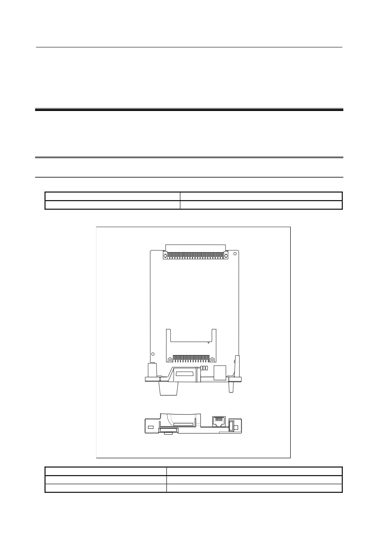
Fast Ethernet Board
-
Specification
Item
Ordering code
Fast Ethernet board
A20B-8101-0030
-
Connector mounting location
JG2
S-BUS back-plane connector
CNH6
CD38R
Connector number
Use
CNH6
ATA card interface
CD38R
100BASE-TX Ethernet interface
- 114 -
4.MATTERS COMMON TO BOTH LCD-MOUNTED TYPE
B-64305EN/03
AND STAND-ALONE TYPE (HARDWARE)
-
LED indications
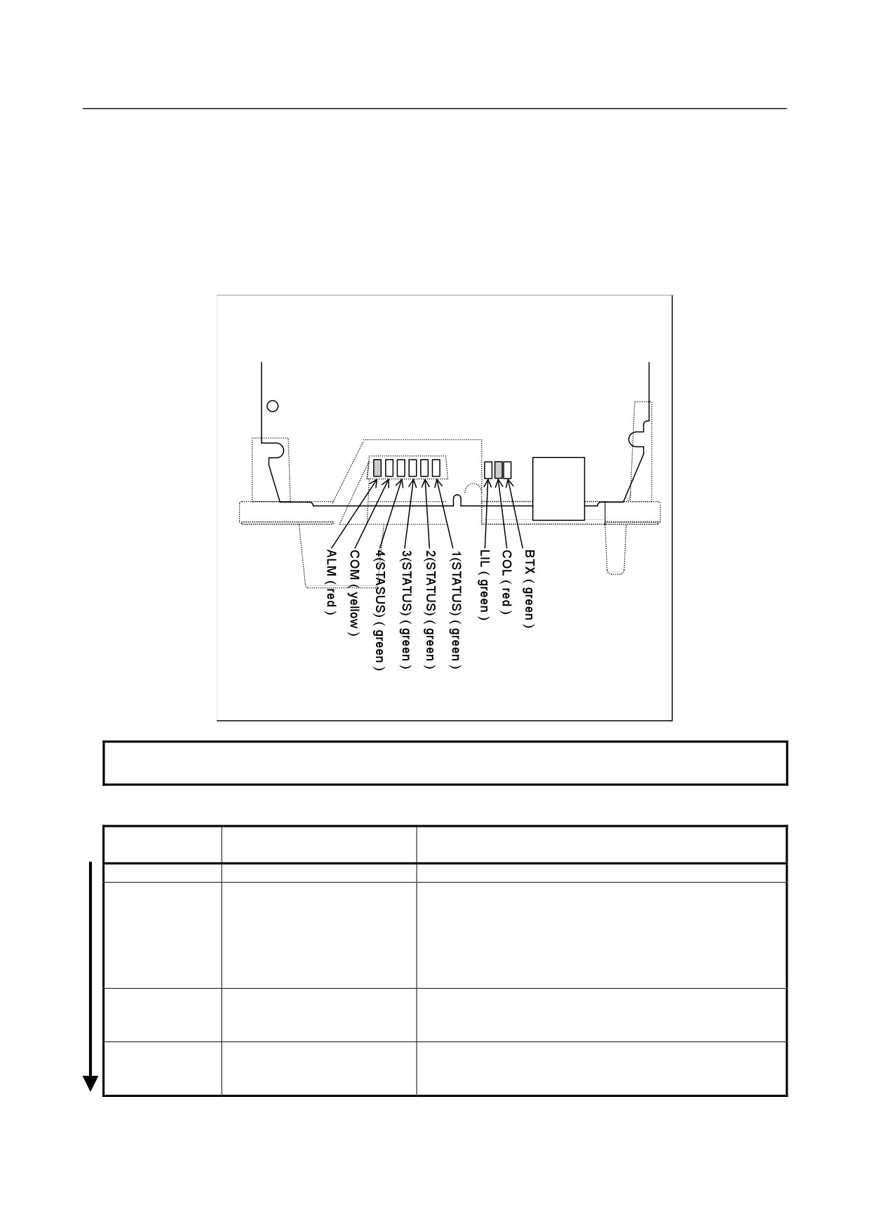
The board incorporates the following LEDs: Four green STATUS LEDs and one red ALARM LED for
indicating the status. Two green LEDs, one yellow LED, and one red LED for indicating the
communication status. The figure below shows the locations of these LEDs. The table below explains the
LED lighting states.
In the following explanations, the LED lighting states are expressed as follows:
: Off
: On
: Blinking
◊: Don't care
Detailed view of LEDs
CD38R
NOTE
The face plate is indicated with dotted line.
LED indication transition for LED1, LED2, LED3, and LED4 (during power-on)
LED indication
Status
Meaning
L4L3L2L1
□□□□
Power-off
■■■■
Immediately after power-on
Initial state entered immediately after power-on.
If the board is stopped in this condition, the cause is one of
the following:
9
The firmware is not stored in the Flash ROM of the
CNC.
9
The board is defective.
■■■□
Start of board
The board has started.
If the board is stopped in this condition, the board may be
defective.
■■□□
Completion of firmware
The firmware has been downloaded to the board.
downloading
If the board is stopped in this condition, the board may be
defective.
- 115 -
4. MATTERS COMMON TO BOTH LCD-MOUNTED TYPE
AND STAND-ALONE TYPE (HARDWARE)
B-64305EN/03
LED indication
Status
Meaning
L4L3L2L1
■□□□
Firmware OS started.
The firmware OS has started.
If the board is stopped in this condition, the cause is one of
the following:
9
The firmware stored in the Flash ROM of the CNC is
destroyed.
9
The board is defective.
□■■■
Completion of firmware OS
Initialization of the firmware OS is completed.
initialization
If the board is stopped in this condition, the cause is one of
the following:
9
The firmware stored in the Flash ROM of the CNC is
destroyed.
9
The board is defective.
□■■☆
Completion of parameter
The Ethernet parameters have been read.
reading
If the board is stopped in this condition, the cause is one of
the following:
9
The Ethernet option or Data Server option is not
installed.
9
The IP address or subnet mask is not set.
□□□☆
Start completion
The board has started normally.
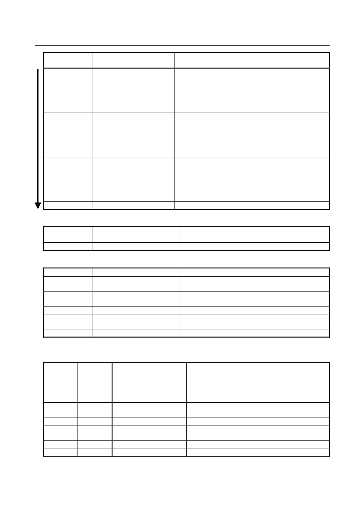
LED indication for LED1, LED2, LED3, and LED4 (during normal operation)
LED indication
Status
Meaning
L4L3L2L1
□□□☆
Normal status
The board is operating normally.
LED indication for BTX, LIL, COM, and ALM (during normal operation)
LED indication
Status
Meaning
BTX
■
100BASE-TX connection in
The communication rate is 100BASE-TX.
progress
BTX
□
10BASE-T connection in
The communication rate is 10BASE-T.
progress
LIL
■
Connected to hub
The board is connected to the hub.
COM
■
Transmission/reception in
Data is being transmitted or received.
progress
ALM
□
No alarm
No alarm is issued
LED indication for LED1, LED2, LED3, and LED4 (when abnormality occurs)
The STATUS LEDs are turned on and off repeatedly with long on-time and short on-time.
LED
LED
indication
indication
[Long
[Short
Status
Description
on-time]
on-time]
4 3 2 1
4 3 2 1
■■□□
□□□■
Error on another board
A defect on another board or a problem on another
board was detected.
■■□□
□□■□
Bus error
Software has a problem, or the board is defective.
■■□□
□□■■
Parity alarm
The board is defective.
■□■□
□□□□
Illegal general instruction
Software has a problem, or the board is defective.
■□■□
□□□■
Illegal slot instruction
Software has a problem, or the board is defective.
■□■□
□■□□
CPU address error
Software has a problem, or the board is defective.
- 116 -
4.MATTERS COMMON TO BOTH LCD-MOUNTED TYPE
B-64305EN/03
AND STAND-ALONE TYPE (HARDWARE)
NOTE
If an error occurs with the LEDs turned on and off with long on-time and short
on-time in a manner not indicated above, contact FANUC.
LED indication for COL, LIL, and ALM (when abnormality occurs)
LED indication
Status
Description
COL
■
Collision occurs.
The LED is on or blinks at short intervals when the Ethernet
COL
☆
(Data collision occurs.)
communication traffic (communication amount) is high or
ambient noise is high.
LIL
□
Not connected to hub
The board is not connected to the hub properly. The LIL LED
stays off also when the power to the hub is off.
Check whether the board is connected to the hub properly.
ALM
■
Parity error occurs.
A parity error occurred in memory on the board. The board is
defective.
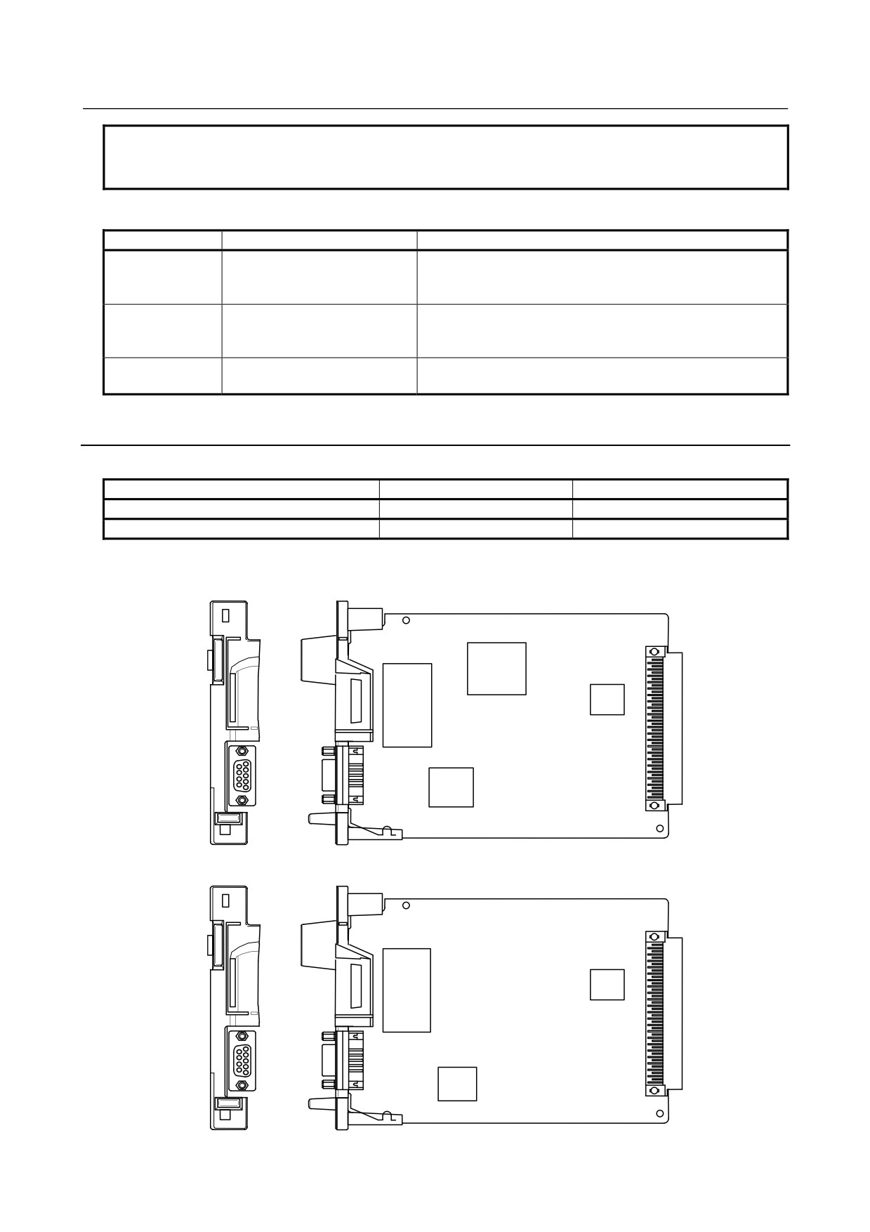
4.1.2
PROFIBUS-DP Board
-
Specification
Item
Ordering code
Remarks
PROFIBUS-DP master board
A20B-8101-0050
PROFIBUS-DP slave board
A20B-8101-0100
-
Connector mounting location
Master board
MPU
DC/DC
converter
LSI
CN1
LSI
Slave board
DC/DC
converter
LSI
CN2
LSI
- 117 -
4. MATTERS COMMON TO BOTH LCD-MOUNTED TYPE
AND STAND-ALONE TYPE (HARDWARE)
B-64305EN/03
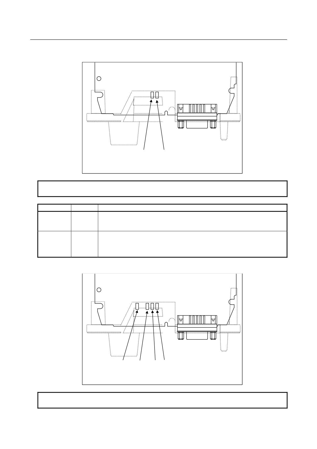
・ LED indicators and their meanings
・ Master board
CN1
LED2
LED1
NOTE
The face plate is indicated by the broken line.
LED name
Color
Description
Indicates that the CPU on this board has started running.
LED1
Green
ON: RESET has been released, allowing the CPU to start running.
The LED is turned off when the power is turned on.
Indicates whether communication is being normally carried out.
ON: Communication is being normally carried out.
LED2
Green
OFF: Communication is not being carried out.
The LED is turned off when the power is turned on.
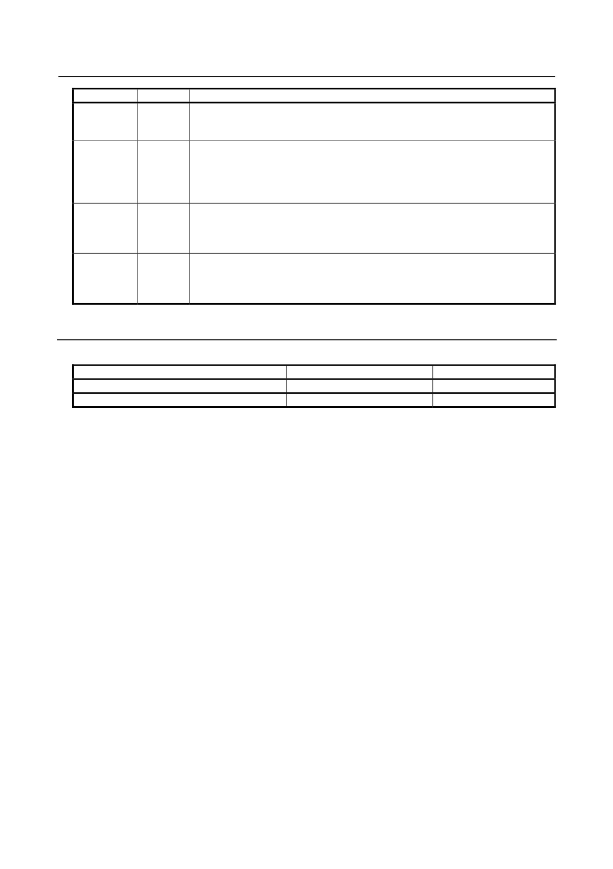
・ Slave board
CN2
LEDB LED3
LED2
LED1
NOTE
The face plate is indicated by the broken line.
- 118 -
4.MATTERS COMMON TO BOTH LCD-MOUNTED TYPE
B-64305EN/03
AND STAND-ALONE TYPE (HARDWARE)
LED name
Color
Description
Indicates that the CPU on this board has started running.
LED1
Green
ON: RESET has been released, allowing the CPU to start running.
The LED is turned off when the power is turned on.
Indicates that communication has started.
ON: Communication has started.
LED2
Green
The LED is turned off when the power is turned on or if:
- No parameter data and configuration data have been received.
- Invalid parameter data and configuration data have been received.
Indicates whether communication is being normally carried out.
ON: Communication is being normally carried out.
LED3
Green
OFF: Communication is not being carried out.
The LED is turned off when the power is turned on.
Indicates that a RAM parity alarm condition has occurred on this board.
ON: A RAM parity alarm condition has occurred.
LEDB
Red
The LED is turned off when the power is turned on. Once it has been turned on, it
stays on until the power is turned off.
4.1.3
DeviceNet Board
Specification
Item
Ordering code
Remarks
DeviceNet master board
A20B-8101-0220
DeviceNet slave board
A20B-8101-0330
- 119 -
4. MATTERS COMMON TO BOTH LCD-MOUNTED TYPE
AND STAND-ALONE TYPE (HARDWARE)
B-64305EN/03
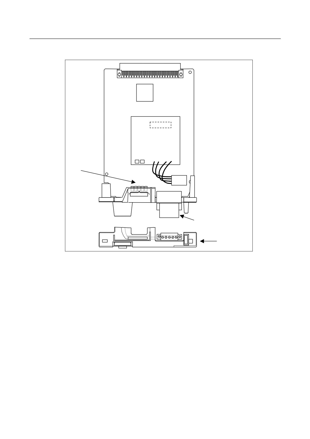
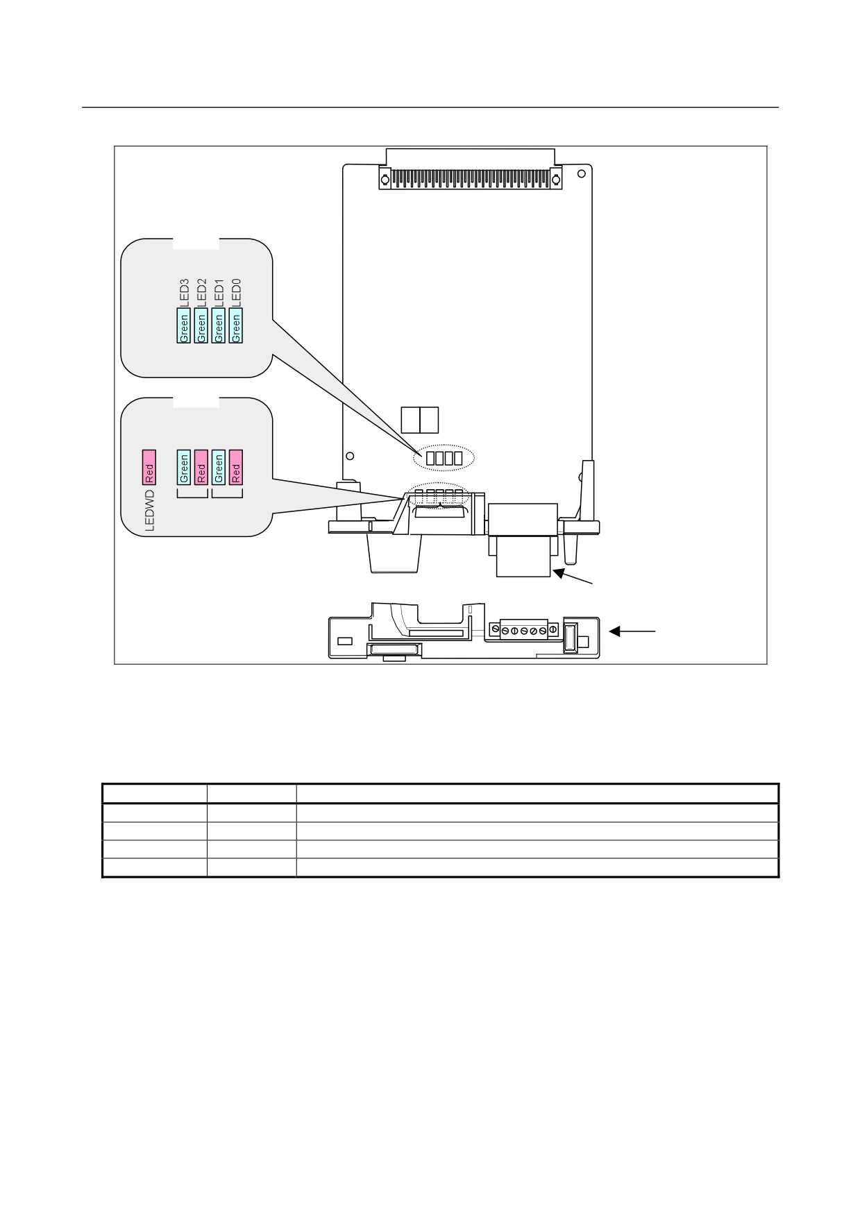
Connector and LED mounting location
-
Master board
LSI
From left to
Daughter board
right
LEDWD
LED3
LED2
NS MS (LED)
LED1
LED0
Outside line connector
TBL
Face plate
- 120 -
4.MATTERS COMMON TO BOTH LCD-MOUNTED TYPE
B-64305EN/03
AND STAND-ALONE TYPE (HARDWARE)
・Slave board
LED
LED
MS NS
Outside line connector
TBL
Face plate
LED indicators and their meanings
・Master board
This board provides four green LEDs and one red LED for status indication.
In addition, the internal daughter board has two LEDs that emit red and green light.
LED name
Color
Meaning
LED0~3
Green
Indicates the activation state of the DeviceNet application software.
LEDWD
Red
Indicates an error on the daughter board.
MS
Red/Green
MS (Module Status) indicates the states of nodes.
NS
Red/Green
NS (Network Status) indicates the state of the network.
In the following explanations, the LED lighting states are expressed as follows:
: Off
: On
: Blinking
◊: Don't care
- 121 -
4. MATTERS COMMON TO BOTH LCD-MOUNTED TYPE
AND STAND-ALONE TYPE (HARDWARE)
B-64305EN/03
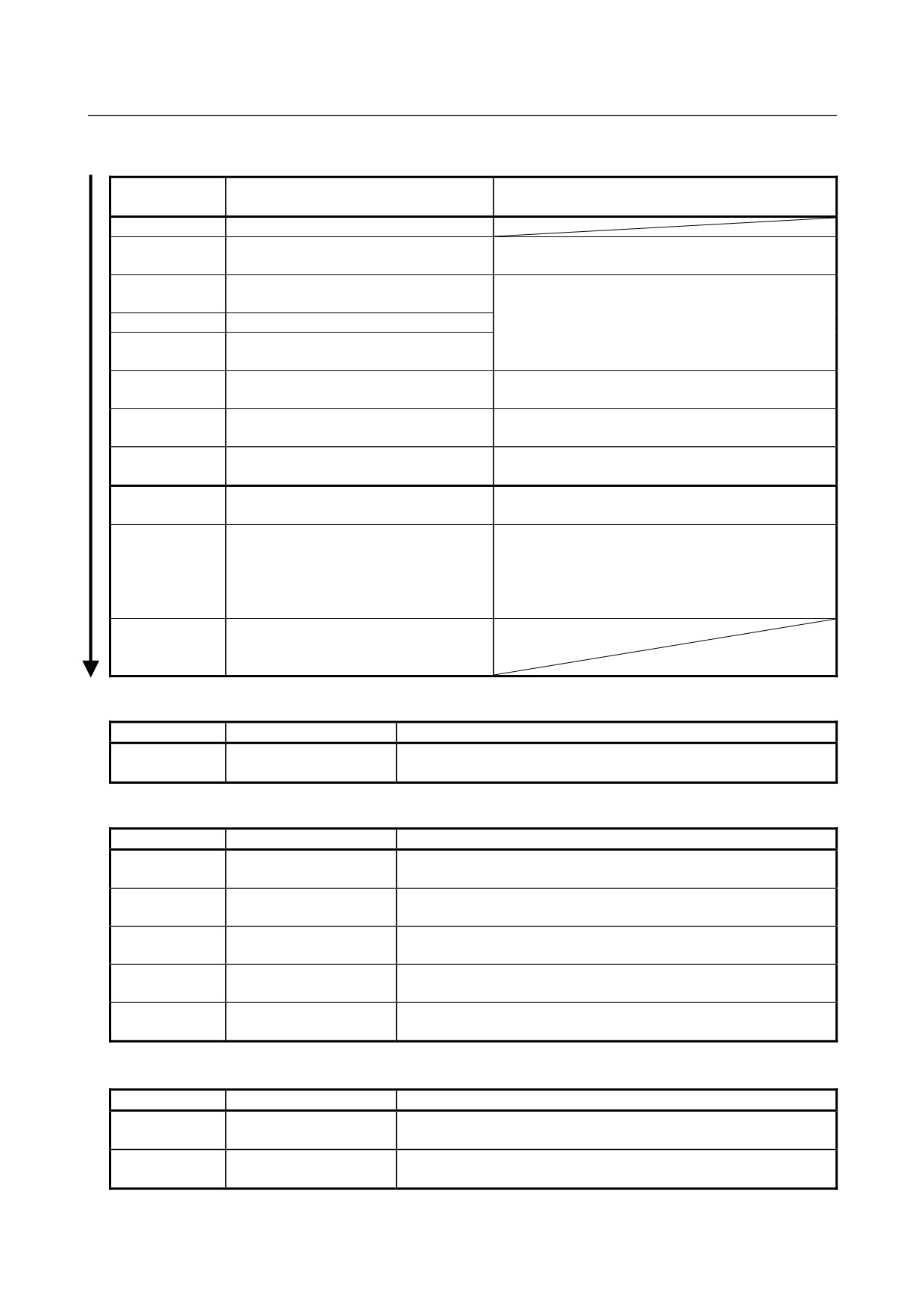
LED indication transition for LED0, LED1, LED2, and LED3 (during power-on)
LED indication
State and cause when stopped after
Action when stopped after power-on
L3L2L1L0
power-on
□□□□
Power-off
■■■■
After power-on, the DeviceNet application
Store the DeviceNet application software in the Flash
software does not start.
ROM of the CNC.
□□□□
Initializing the firmware on the daughter
Replace the DeviceNet master board.
board.
□□□■
Checking memory on the daughter board.
□□■□
Recognizing the firmware on the daughter
board.
□□■■
Enable the DeviceNet master function (software
Reading DeviceNet parameters.
option).
□■□□
Verifying that DeviceNet parameter
Set DeviceNet parameter "NETWORK" to "ONLINE."
"NETWORK" is set to "ONLINE."
□■□■
Setting the bus parameter in DeviceNet
Replace the DeviceNet master board.
parameters.
□■■□
Setting the slave parameter in DeviceNet
Set the slave parameter in DeviceNet parameters
parameters.
correctly. Or, replace the DeviceNet master board.
□■■■
Check duplication with the MAC ID of a slave device.
Check if cables are connected correctly.
Checking duplicate MAC IDs.
Check if power for communication is correctly
supplied.
Check if slave devices are turned on.
■□□□
The DeviceNet application software has
been initialized and I/O communication
starts.
LED indication of LEDWD
LED indication
Status
Meaning
■
The daughter board failed.
Daughter board failure
Replace the DeviceNet master board.
LED indication of MS and N (during normal operation)
LED indication
Status
Meaning
MS □
Immediately after
The MPU on the daughter board is being reset.
NS □
power-on
MS ☆ Green
Initializing
The firmware on the daughter board is making a initialization.
NS □
MS ■ Green
Checking duplication of
The firmware on the daughter board is checking duplicated MAC IDs.
NS □
MAC IDs
MS ■ Green
I/O communication
The firmware on the daughter board is stopping I/O communication.
NS ☆ Green
stopped
MS ■ Green
I/O communication in
The firmware on the daughter board is successfully performing I/O
NS ■ Green
advance
communication.
LED indication of MS and NS (when abnormality occurs)
LED indication
Status
Error and action
MS ☆ Red
Daughter board failure
The daughter board failed.
NS ◇
Replace the DeviceNet master board.
MS ■ Red
Daughter board failure
The daughter board failed.
NS □
Replace the DeviceNet master board.
- 122 -
4.MATTERS COMMON TO BOTH LCD-MOUNTED TYPE
B-64305EN/03
AND STAND-ALONE TYPE (HARDWARE)
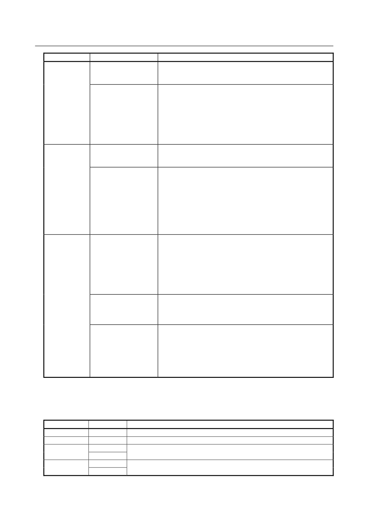
LED indication
Status
Error and action
MS ◇
MAC IDs are duplicate.
NS ■ Red
Duplicate MAC IDs
Verify the following:
→ MAC IDs are not duplicate by check the MAC IDs of all nodes.
Communication stopped because a communication error occurred
frequently.
Verify the following:
→ The communication rates of all nodes are set to the same value.
Busoff detection
→ The cable length is appropriate.
→ The cable is not loose or broken.
→ A terminal is placed on only both ends of the main line.
→ There are not much noise.
MS ◇
Power for communication is not supplied.
NS □
Network power failure
Verify the following:
→ Power for communication is properly supplied.
Transmission is not completed successfully.
Verify the following:
→ All slaves are turned on.
→ There is no other master on the network.
Transmission error
→ The communication rates of all nodes are set to the same value.
→ The cable length is appropriate.
→ The cable is not loose or broken.
→ A terminal is placed on only both ends of the main line.
→ There are not much noise.
MS ◇
No slaves are present.
NS ☆ Red
Verify the following:
→ The slave is turned on.
→ The communication rates of all nodes are set to the same value.
Slave not present
→ The cable length is appropriate.
→ The cable is not loose or broken.
→ A terminal is placed on only both ends of the main line.
→ There are not much noise.
The slave I/O size setting does not match the setting of the actual
slave.
Slave I/O size mismatch
Verify the following:
→ The slave I/O size setting matches the setting of the actual slave.
I/O communication timed out.
Verify the following:
→ The communication rates of all nodes are set to the same value.
I/O communication error
→ The cable length is appropriate.
→ The cable is not loose or broken.
→ A terminal is placed on only both ends of the main line.
→ There are not much noise.
Slave board
This board provides four green LEDs (LED0 to LED3) and one red LED (LEDWD) for status indication.
In addition, there are two LED sets (MS and NS) that consist of one red LED and one green LED.
LED name
Color
Meaning
LED0~3
Green
Indicates the activation state of the DeviceNet application software.
LEDWD
Red
Indicates an error on the board.
Green
Indicates the unit status, which is the status of the local node.
MS
Red
Green
Indicates the network status, which is the status of the entire network including the
NS
Red
local node.
- 123 -
4. MATTERS COMMON TO BOTH LCD-MOUNTED TYPE
AND STAND-ALONE TYPE (HARDWARE)
B-64305EN/03
In the following explanations, the LED lighting states are expressed as follows:
: Off
: On
: Blinking
◊: Don't care
?: Undefined
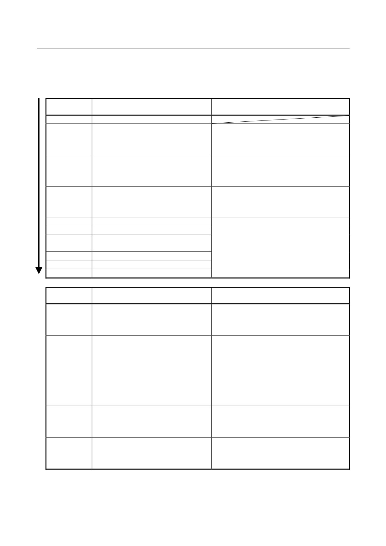
LED indication transition for LED0, LED1, LED2, and LED3
LED indication
State and cause when stopped after
Action when stopped after power-on
L3L2L1L0
power-on
□□□□
Power-off
■■■■
Store the DeviceNet application software in the
After power-on, the DeviceNet application
Flash ROM of the CNC.
software does not start. Or, the DeviceNet
Or, confirm that the DeviceNet slave function
slave function (software option) is disabled.
(software option) has been purchased.
□□□□
Remove the noise factor and then turn the slave
power off and back on again.
Initializing the firmware on the board.
When the error persists, replace the DeviceNet
slave board.
□□□■
Remove the noise factor and then turn the slave
power off and back on again.
The board firmware has been initialized.
When the error persists, replace the DeviceNet
slave board.
□□■□
A line baud rate check is in progress.
□□■■
A MAC ID duplication check is in progress.
These faults are recoverable.
□■□□
Waiting for I/O communication to be
When communication is normally established, the
established.
status changes to "I/O communication is normal".
□■□■
I/O communication is normal.
Each status corresponds to DeviceNet MPU status
□■■□
I/O communication has timed out.
transition NOTE).
□■■■
I/O communication is idle.
LED indication
State and cause when stopped after
Action when stopped after power-on
L3L2L1L0
power-on
Check the following and then turn the slave power
These faults are not recoverable on the
↑
↓
off and back on again.
board side.
→ MAC IDs are not duplicate by check the MAC
MAC ID duplication has been detected.
(Repetition)
IDs of all nodes.
Check the following and then turn the slave power
off and back on again.
→ The communication rates of all nodes are set to
These faults are not recoverable on the
the same value.
↑
↓
board side.
→ The cable length is appropriate.
Busoff was detected due to frequent
→ The cable is not loose or broken.
(Repetition)
occurrence of a communication error.
→ A terminal is placed on only both ends of the
main line.
→ There are not much noise.
Any of other unrecoverable failures occurred
Remove the noise factor and then turn the slave
↑
↓
on the board.
power off and back on again.
? ? ?
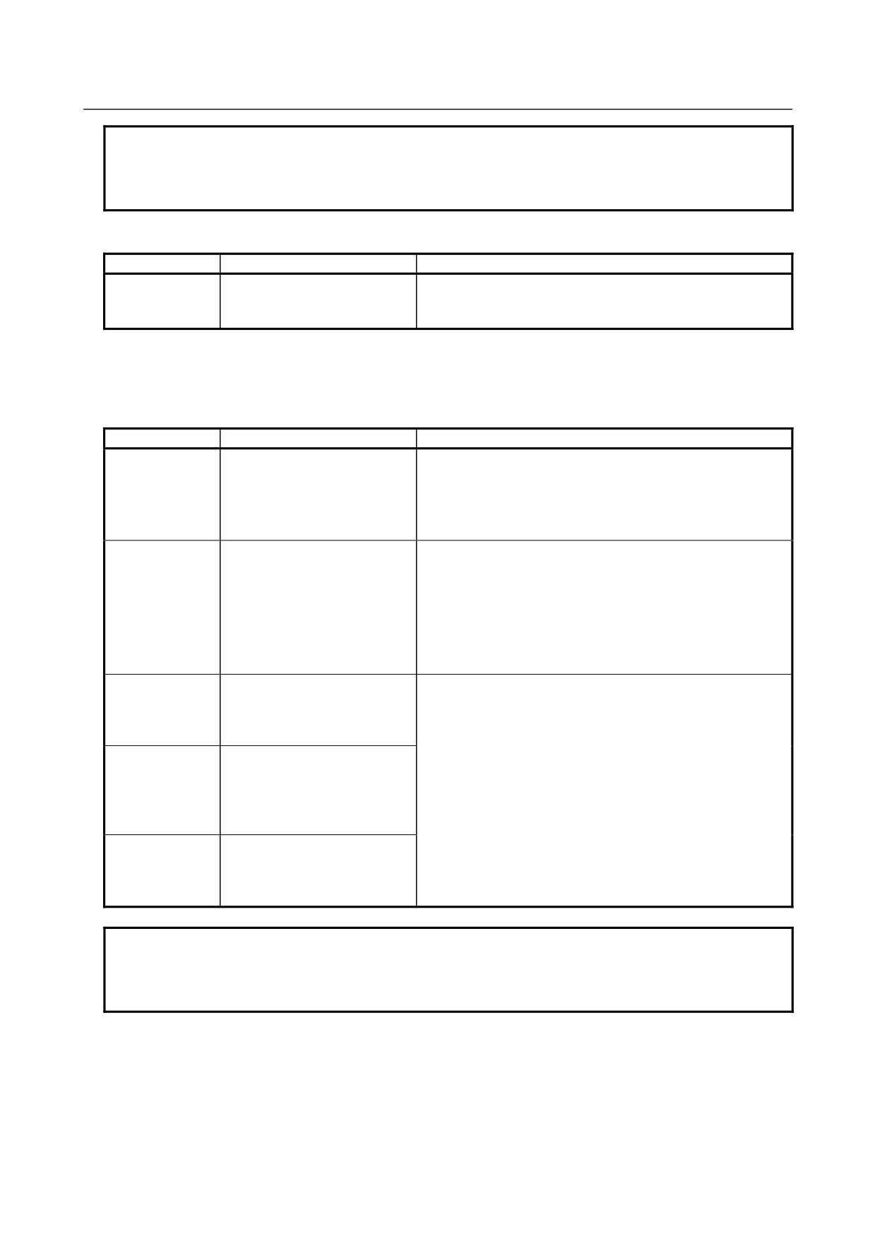
The pattern indicated by LED0 to LED2 is
When the error persists, replace the DeviceNet
(Repetition)
other than the above two patterns.
slave board.
↑
↓
An unrecoverable failure occurred on the
Contact FANUC.
CNC side.
(Repetition)
- 124 -
4.MATTERS COMMON TO BOTH LCD-MOUNTED TYPE
B-64305EN/03
AND STAND-ALONE TYPE (HARDWARE)
NOTE
When a transition to the "I/O communication normal" status is not made, confirm
that the power for communication is correctly supplied because a network power
failure may have occurred.
LED indication of LEDWD
LED indication
Status
Meaning
Remove the noise factor and then turn the slave power off and
Board failure
back on again.
When the error persists, replace the DeviceNet slave board.
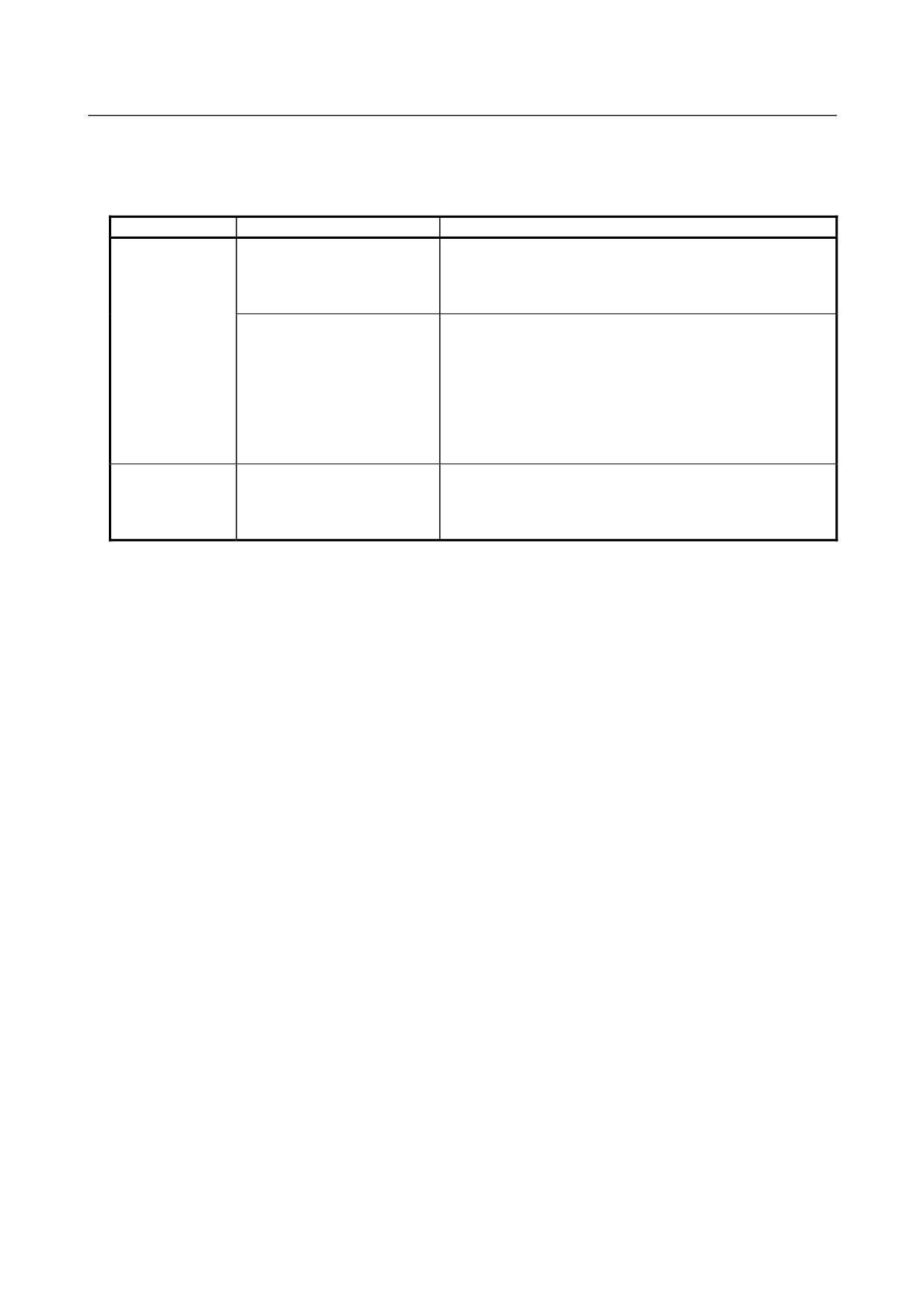
LED indication of MS and NS (during normal operation)
In the "during normal operation" status, when communication is normally established, a transition to the
"I/O communication normal" status is made.
LED indication
Status
Meaning
MS □ Green
MS □ Red
The onboard firmware is being initialized when the onboard
NS □ Green
Immediately after power-on
MPU is in the reset status or reset release status.
NS □ Red
MS ■ Green
MS □ Red
The onboard firmware performs processing in the order below.
NS □ Green
<1>Waits for the DeviceNet application software to be
NS □ Red
Communication under
initialized.
preparation
<2> Checks the baud rate.
<3> Checks MAC ID duplication.
MS ■ Green
Waiting for establishment of I/O
MS □ Red
communication to be
NS ☆ Green
established
NS □ Red
MS ■ Green
MS □ Red
Each status corresponds to DeviceNet MPU status transition
NS ■ Green
I/O communication normal
NOTE)
NS □ Red
MS ◇ Green
MS ◇ Red
I/O communication timeout
NS ■ Green
NS ☆ Red
NOTE
When a transition to the "I/O communication normal" status is not made, confirm
that the power for communication is correctly supplied because a network power
failure may have occurred.
- 125 -
4. MATTERS COMMON TO BOTH LCD-MOUNTED TYPE
AND STAND-ALONE TYPE (HARDWARE)
B-64305EN/03
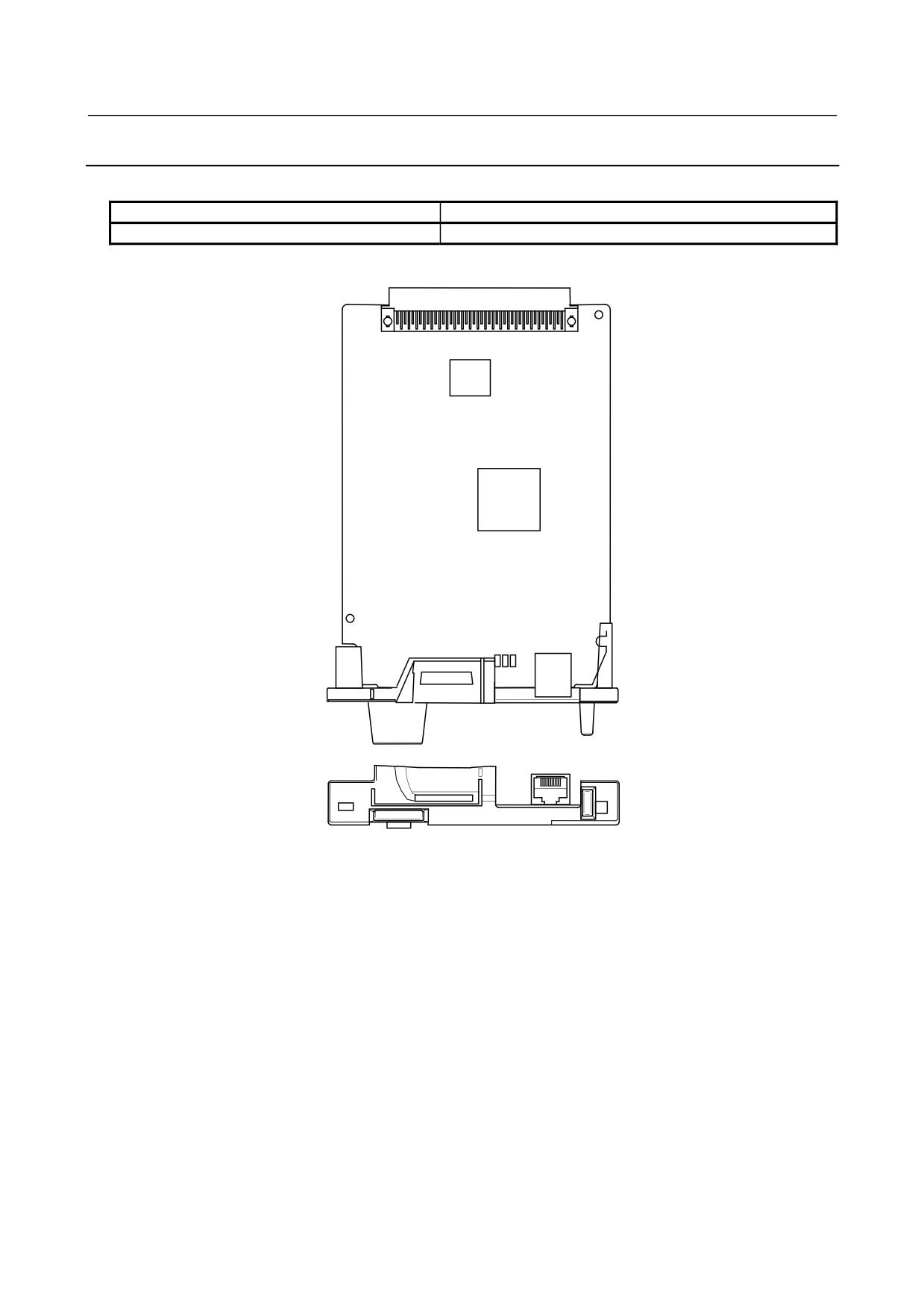
LED indication of MS and NS (during occurrence of an unrecoverable failure)
In the "during occurrence of an unrecoverable failure" status, once an error occurred, recovery is not
performed unless this slave station is powered off and back on again.
LED indication
Status
Error and action
MS ◇ Green
Check the following and then turn the slave power off and back
MS ◇ Red
on again.
Duplicate MAC IDs
NS □ Green
→ MAC IDs are not duplicate by check the MAC IDs of all
NS ■ Red
nodes.
Check the following and then turn the slave power off and back
on again.
→ The communication rates of all nodes are set to the same
value.
Busoff detection
→ The cable length is appropriate.
→ The cable is not loose or broken.
→ A terminal is placed on only both ends of the main line.
→ There are not much noise.
MS □ Green
Remove the noise factor and then turn the slave power off and
MS ■ Red
Other unrecoverable onboard
back on again.
NS ◇ Green
failures
When the error persists, replace the DeviceNet slave board.
NS ◇ Red
- 126 -
4.MATTERS COMMON TO BOTH LCD-MOUNTED TYPE
B-64305EN/03
AND STAND-ALONE TYPE (HARDWARE)
4.1.4
FL-net Board
-
Specification
Item
Ordering code
FL-net board
A20B-8101-0031
-
Connector mounting location
LSI
MPU
CD38N
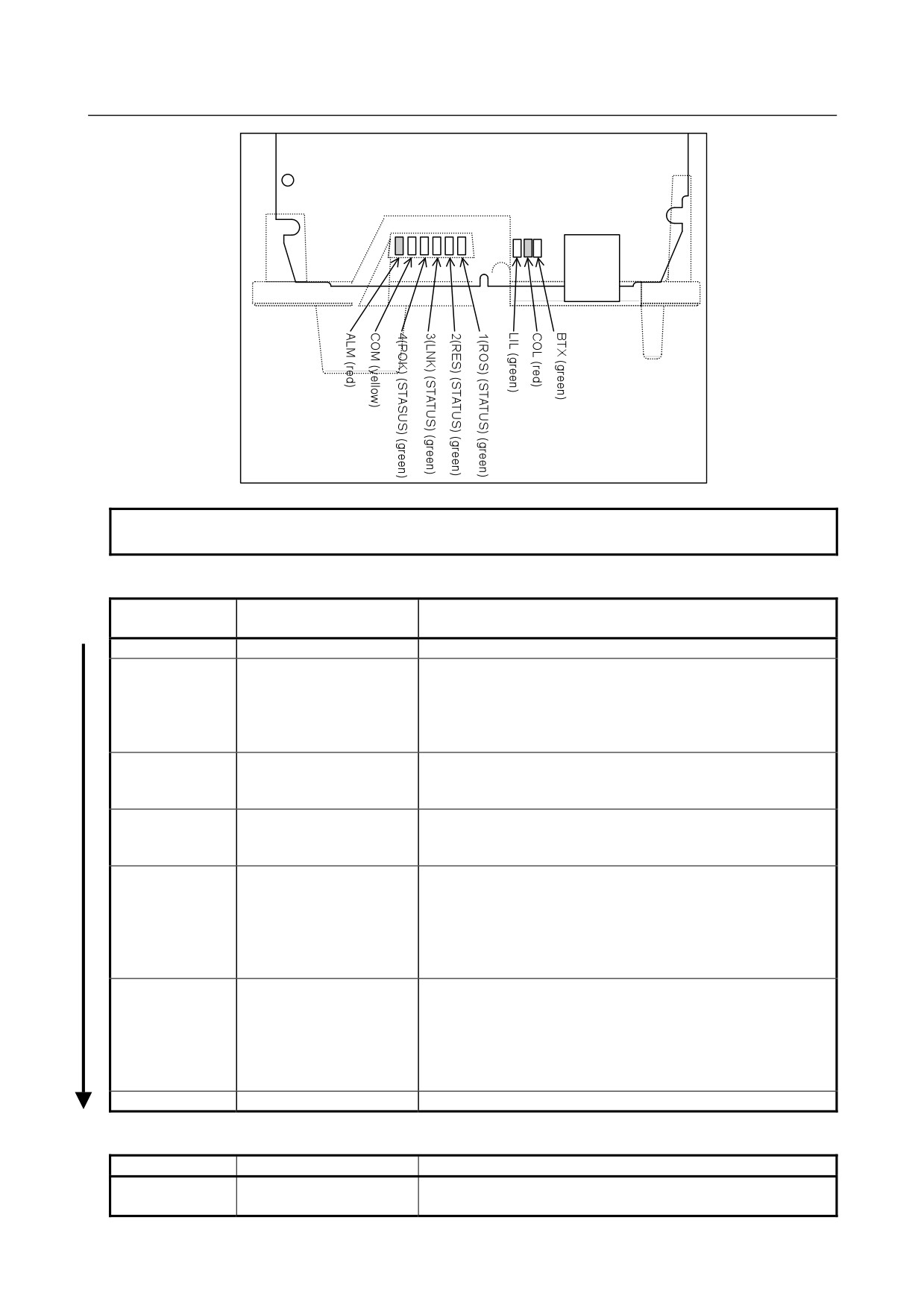
・ LED indicators and their meanings
The board incorporates the following LEDs: Four green STATUS LEDs and one red ALARM LED for
indicating the status. Two green LEDs, one yellow LED, and one red LED for indicating the
communication status. The figure below shows the locations of these LEDs. The table below explains the
LED lighting states.
In the following explanations, the LED lighting states are expressed as follows:
: Off
: On
: Blinking
◊: Don't care
- 127 -
4. MATTERS COMMON TO BOTH LCD-MOUNTED TYPE
AND STAND-ALONE TYPE (HARDWARE)
B-64305EN/03
CD38N
NOTE
The face plate is indicated by the broken line.
LED display transition for LED1, LED2, LED3, and LED4 (during power-on)
LED indication
Status
Meaning
4 3 2 1
□□□□
Power-off
■■■■
Immediately after
Initial state entered immediately after power-on.
power-on
If the board is stopped in this condition, the cause is one of the
following:
9
The firmware is not stored in the Flash ROM of the CNC.
9
The board is defective.
■■■□
Start of board
The board has started.
If the board is stopped in this condition, the board may be
defective.
■■□□
Completion of firmware
The firmware has been downloaded to the board.
downloading
If the board is stopped in this condition, the board may be
defective.
■□□□
Firmware OS started.
The firmware OS has started.
If the board is stopped in this condition, the cause is one of the
following:
9
The firmware stored in the Flash ROM of the CNC is
destroyed.
9
The board is defective.
□■■■
Completion of firmware
Initialization of the firmware OS is completed.
OS initialization
If the board is stopped in this condition, the cause is one of the
following:
9
The firmware stored in the Flash ROM of the CNC is
destroyed.
9
The board is defective.
◇◇□☆
Start completion
The board has started normally.
LED display for LED1, LED2, LED3, and LED4 (during normal operation)
LED indication
Status
Meaning
ROS
☆
Normal software operation
Blinks at 1-second intervals when the communication software on
the FL-net board operates normally.
- 128 -
4.MATTERS COMMON TO BOTH LCD-MOUNTED TYPE
B-64305EN/03
AND STAND-ALONE TYPE (HARDWARE)
LED indication
Status
Meaning
RES
□
Normally OFF
Normally, off
LNK
■
Participating in network
Turned on when the node participates in the FL-net network
POK
■
Normal parameters
Turned on when all FL-net parameters are valid.
LED display for BTX, LIL, COM, and ALM (during normal operation)
LED indication
Status
Meaning
BTX
□
10BASE-T connection in progress
The communication rate is 10BASE-T.
BTX
■
100BASE-TX connection in progress
The communication rate is 100BASE-TX.
LIL
■
Connected to hub
The board is connected to the hub.
COM
■
Transmission/reception in progress
Data is being transmitted or received.
ALM
□
No alarm
No alarm is issued
(HER)
LED display for LED1, LED2, LED3, and LED4 (when abnormality occurs)
The STATUS LEDs are turned on and off repeatedly with long on-time and short on-time.
LED indication
LED indication
[Long on-time]
[Short on-time]
Status
Description
4 3 2 1
4 3 2 1
■■□□
□□□■
Error on another
A defect on another board or a problem on another
board
board was detected.
■■□□
□□■□
Bus error
Software has a problem, or the board is defective.
■■□□
□□■■
Parity alarm
The board is defective.
■□■□
□□□□
Illegal general
Software has a problem, or the board is defective.
instruction
■□■□
□□□■
Illegal slot instruction
Software has a problem, or the board is defective.
■□■□
□■□□
CPU address error
Software has a problem, or the board is defective.
NOTE
If an error occurs with the LEDs turned on and off with long on-time and short
on-time in a manner not indicated above, contact FANUC.
LED display for COL, LIL, and ALM (when abnormality occurs)
LED indication
Status
Description
COL
■
Collision occurs.
When a data collision occurs on the network, the LED is lit or blinks.
(Note)
COL
☆
(Data collision occurs.)
LIL
□
Not connected to hub
The board is not connected to the hub properly. The LIL LED stays
off also when the power to the hub is off.
Check whether the board is connected to the hub properly.
ALM
■
Parity error occurs.
A parity error occurred in memory on the board. The board is
(HER)
defective.
NOTE
The FL-net manages the token-based transmission right so that no collision
occurs. If this LED is turned on frequently, a communication error has occurred
due to noise, or an Ethernet compliant product other than the FL-net is
connected.
In such a case, check the devices connected to the network and the network
installation status.
- 129 -
4. MATTERS COMMON TO BOTH LCD-MOUNTED TYPE
AND STAND-ALONE TYPE (HARDWARE)
B-64305EN/03
4.2
INSERTING AND EXTRACTING OPTION PCB
WARNING
Only those personnel who have received approved safety and maintenance
training may perform this replacement work.
When opening the cabinet and replacing the card PCB, be careful not to touch
the high-voltage circuits (marked
and fitted with an insulating cover).
Touching the uncovered high-voltage circuits presents an extremely dangerous
electric shock hazard.
CAUTION
Before replacing a printed circuit board, be sure to read Section 4.11,
“CAUTIONS IN REPLACING PCB’S,” to confirm the procedure.
Before starting replacement work, back up the SRAM data of the CNC.
Otherwise, the SRAM data may be lost during replacement work. See Section
3.9, “MAINTENANCE OF STAND-ALONE TYPE UNIT”, Chapter 5, “INPUT AND
OUTPUT OF DATA” or Appendix F, “MAINTENANCE OF OPEN CNC
(BOOT-UP AND IPL)” for explanations about how to save the contents of the
SRAM memory.
4.2.1
Method of Extraction
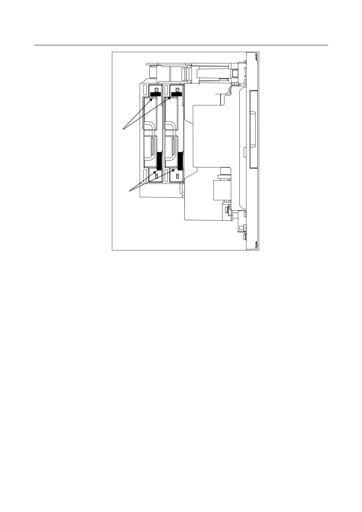
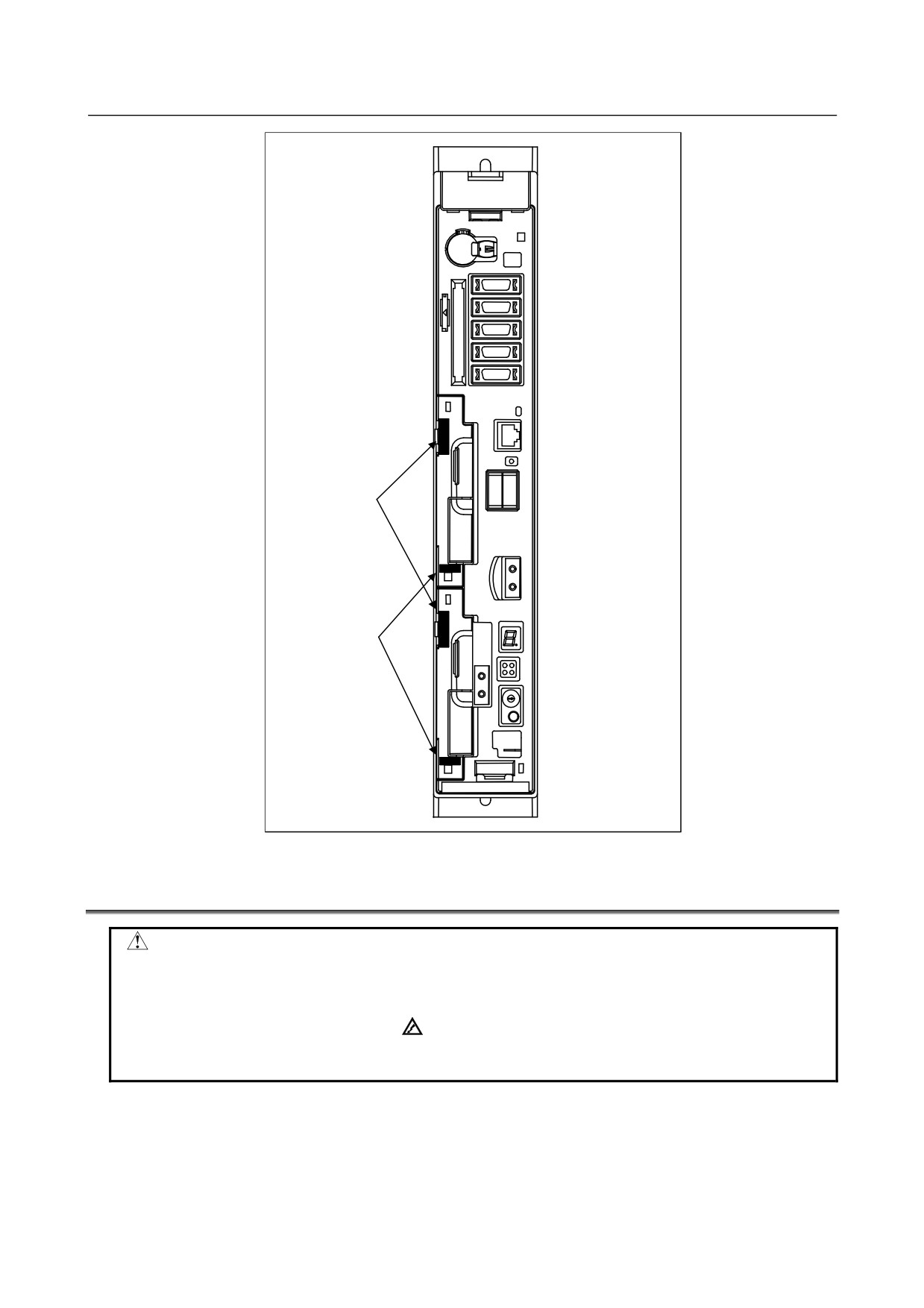
<1> Detach the cable connected to the option board and the cable that interferes when the option board is
extracted.
<2> Pinch handles A and B for extraction.
<3> Pinch handle A, and extract the printed circuit board while disengaging the latch.
4.2.2
Method of Insertion
<1> Pinch handles A and B for extraction, then insert the option board until the option board plugs into
the connector of the back panel.
<2> Plug the detached cables again correctly.
- 130 -
4.MATTERS COMMON TO BOTH LCD-MOUNTED TYPE
B-64305EN/03
AND STAND-ALONE TYPE (HARDWARE)
B
A
For LCD-mounted type control unit
- 131 -
4. MATTERS COMMON TO BOTH LCD-MOUNTED TYPE
AND STAND-ALONE TYPE (HARDWARE)
B-64305EN/03
A
B
For stand-alone type control unit
4.3
MOUNTING AND DEMOUNTING AXIS CARD
WARNING
Only those personnel who have received approved safety and maintenance
training may perform this replacement work.
When opening the cabinet and replacing a card PCB, be careful not to touch the
high-voltage circuits (marked
and fitted with an insulating cover).
Touching the uncovered high-voltage circuits presents an extremely dangerous
electric shock hazard.
- 132 -
4.MATTERS COMMON TO BOTH LCD-MOUNTED TYPE
B-64305EN/03
AND STAND-ALONE TYPE (HARDWARE)
CAUTION
Before replacing a printed circuit board, be sure to read Section 4.11,
“CAUTIONS IN REPLACING PCB’S,” to confirm the procedure.
Before starting replacement work, back up the SRAM data of the CNC.
Otherwise, the SRAM data may be lost during replacement work. See Section
3.9, “MAINTENANCE OF STAND-ALONE TYPE UNIT”, Chapter 5, “INPUT AND
OUTPUT OF DATA” or Appendix F, “MAINTENANCE OF OPEN CNC
(BOOT-UP AND IPL” for explanations about how to save the contents of the
SRAM memory.
4.3.1
Method of Extraction
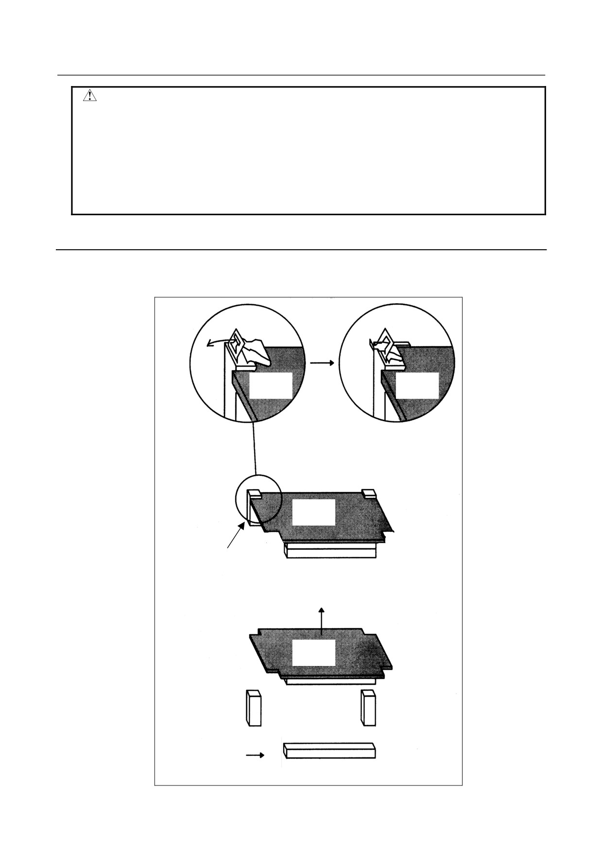
<1> Pull outward and unlatch the two claws of the spacer fixing the axis card. (Fig. a)
<2> Pull up (in a direction perpendicular to the main board) and out the axis card. (Fig. b)
Axis card
Axis card
Axis card
Fig. a
Spacer
Connector
Axis card
Fig. bSpacer
Connector
- 133 -