FANUC Series 0i-MODEL D, FANUC Series 0i Mate-MODEL D. MAINTENANCE MANUAL - page 4
2.LCD-MOUNTED TYPE CNC HARDWARE
B-64305EN/03
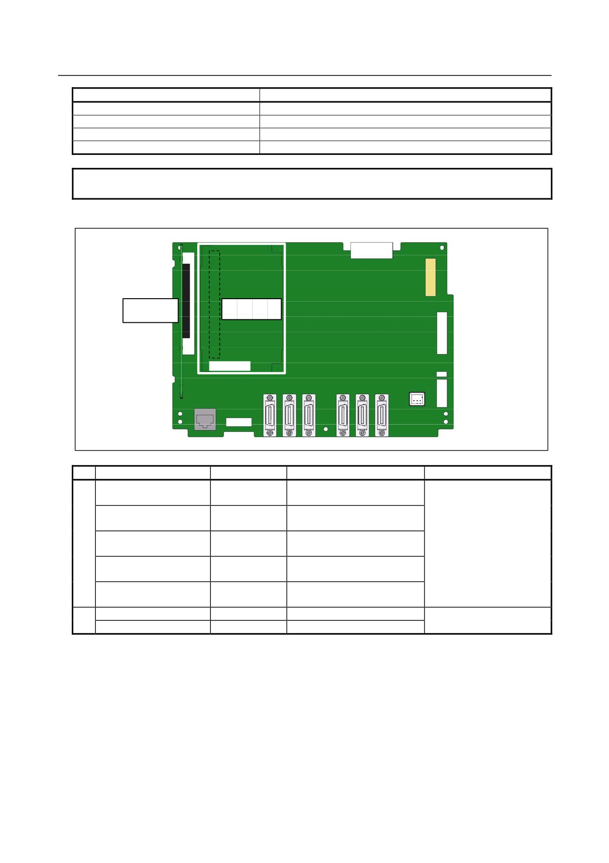
Connector number
Application
CA88A
PCMCIA interface
CA122
Soft key
CA121
Inverter
CD38A
Ethernet
NOTE
RS-232-C serial port 2 is also used as a touch panel interface.
Axis card and power supply mounting location
(2) Power
(1) Axis card
supply
Connector
No.
Name
Specification
Function
Remarks
(1)
Axis card A1
A20B-3300-0635
Path 1 control, supporting up to
The maximum number of
2 axes
axes is also limited depending
Axis card A2
A20B-3300-0638
Path 1 control, supporting up to
on the model.
4 axes
Axis card A3
A20B-3300-0637
Path 1 control, supporting up to
5 axes
Axis card B2
A20B-3300-0632
Path 2 lathe control, supporting
up to 6 axes
Axis card B3
A20B-3300-0631
Path 2 lathe control, supporting
up to 8 axes
(2)
Power supply (no slot)
A20B-8200-0560
No slot
Power supply (2 slots)
A20B-8200-0570
2 slots
- 74 -
B-64305EN/03
2.LCD-MOUNTED TYPE CNC HARDWARE
-
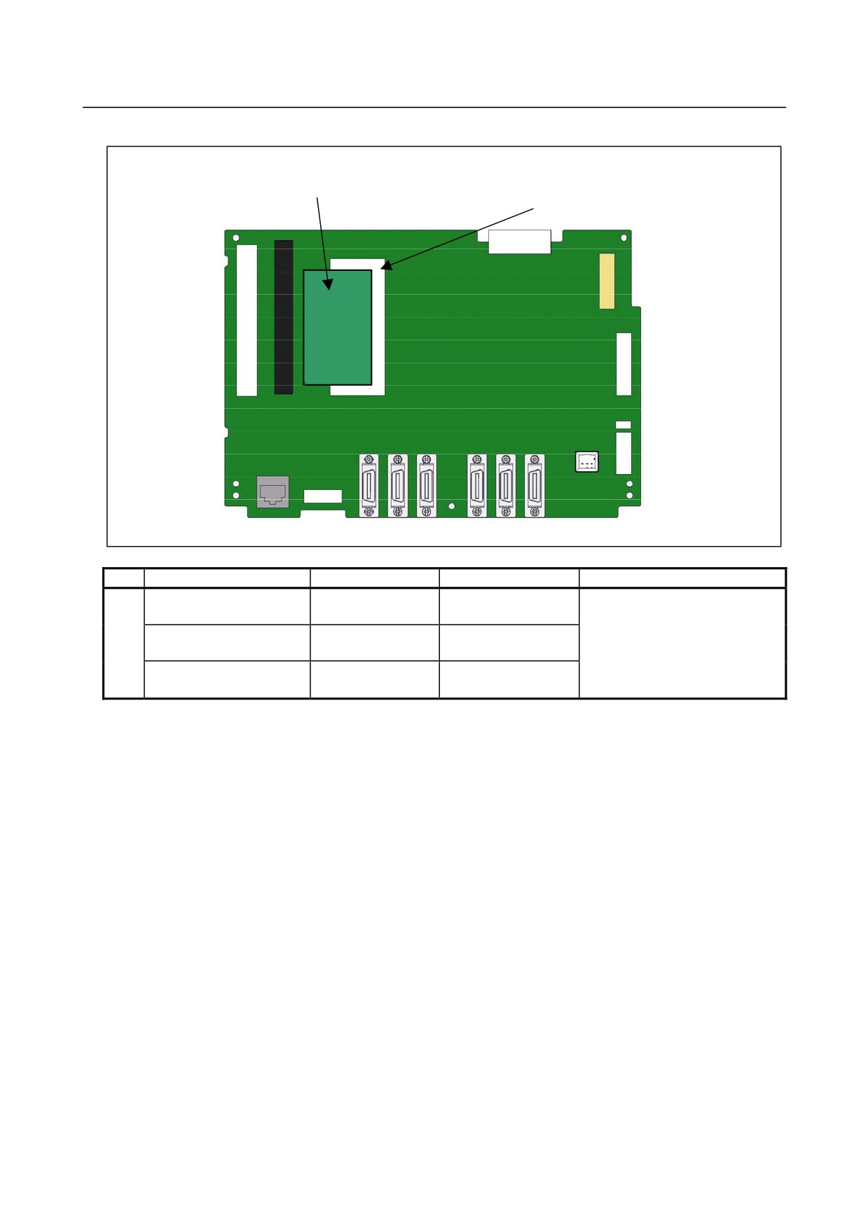
FROM/SRAM module mounting location
(1) FROM/SRAM module
DIMM module socket
No.
Name
Specification
Function
Remarks
①
FROM/SRAM module A1
A20B-3900-0242
FROM 64MB
The FROM stores various control
SRAM 1MB
software programs, user software
FROM/SRAM module B1
A20B-3900-0240
FROM 128MB
programs, and so forth.
SRAM 1MB
The SRAM is a battery-backed
FROM/SRAM module B2
A20B-3900-0241
FROM 128MB
memory module.
SRAM 2MB
- 75 -
2.LCD-MOUNTED TYPE CNC HARDWARE
B-64305EN/03
-
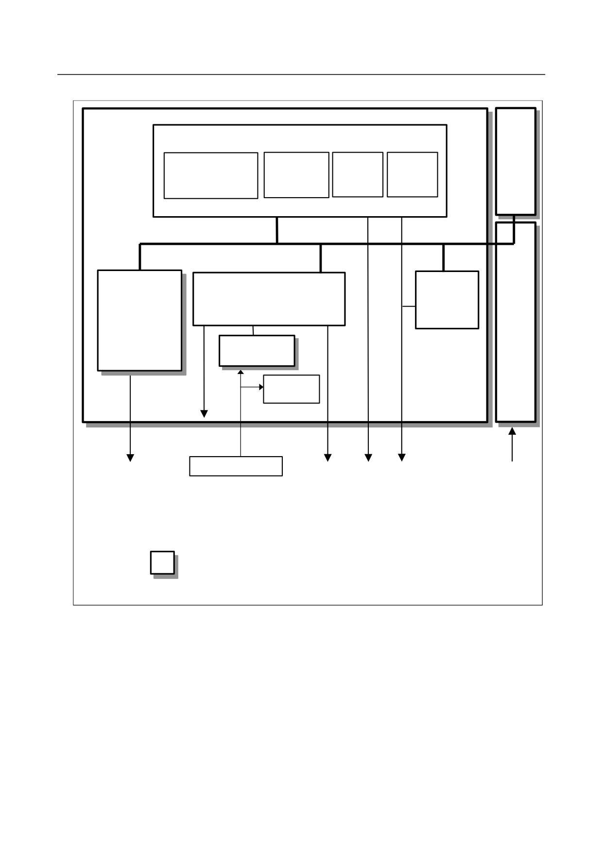
Block diagram
Optional
Main board
board
CPU circuit
CPU
Main
BOOT
I/O Link
memory
software
control
Power
Axis card
Peripheral control
PMC control
supply
I/O Link
control
DIMM module
FROM/SRAM
Calendar
function
Display unit
Lithium battery
FSSB
MDI
Ethernet
I/O Link
24VDC
RS-232-C
Memory card
Serial spindle
HDI
: Detachable card, module, or printed circuit board
- 76 -
B-64305EN/03
2.LCD-MOUNTED TYPE CNC HARDWARE
-
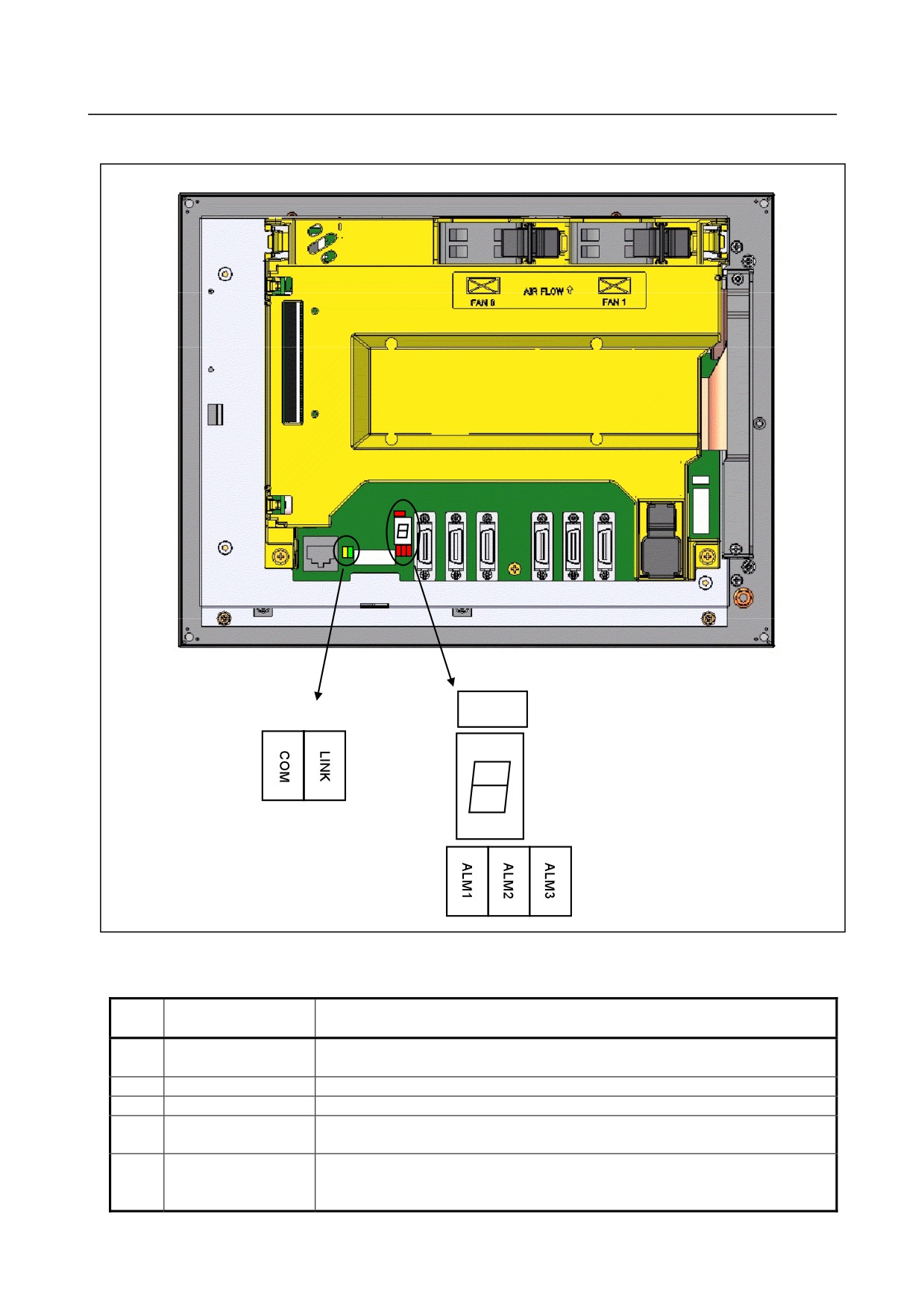
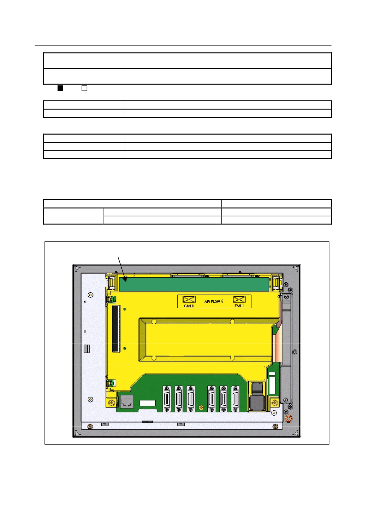
LED display
Rear of unit
(2) Ethernet status
LOWV
(1) Alarm (red)
(3) 7-segment LED
(yellow) (green)
(1) Alarm (red)
(1) Alarm LED (red) indication at system alarm occurrence
If any of these LEDs lights, it is likely that the hardware is defective.
Alarm LED
No.
Meaning
1
2
3
1
□
■ □
Low battery voltage.
The battery may be is running out.
2
■ ■ □
Software detected an error and stopped the system.
3
□ □ ■
Hardware detected a failure in the system.
4
■ □ ■
An alarm was issued with the axis card.
The axis card or servo amplifier may be faulty, or the FSSB may be broken.
5
□ ■ ■
An error was detected in the data of the SRAM on the FROM/SRAM module.
The FROM/SRAM module may be faulty, the battery voltage may have dropped, or
the main board may be faulty.
- 77 -
2.LCD-MOUNTED TYPE CNC HARDWARE
B-64305EN/03
Alarm LED
No.
Meaning
1
2
3
6
■
■ ■
Abnormal power supply operation.
The cause may be noise or a power supply failure.
: On
: Off
LED Name
Meaning
LOWV
The main board (CPU circuit) may be faulty.
(2) Ethernet status LED
LED Name
Meaning
LINK (green)
Turned on when a connection is made with the hub correctly
COM (yellow)
Turned on when data is transferred
(3)
7-segment LED
See Appendix E, “LED Display”.
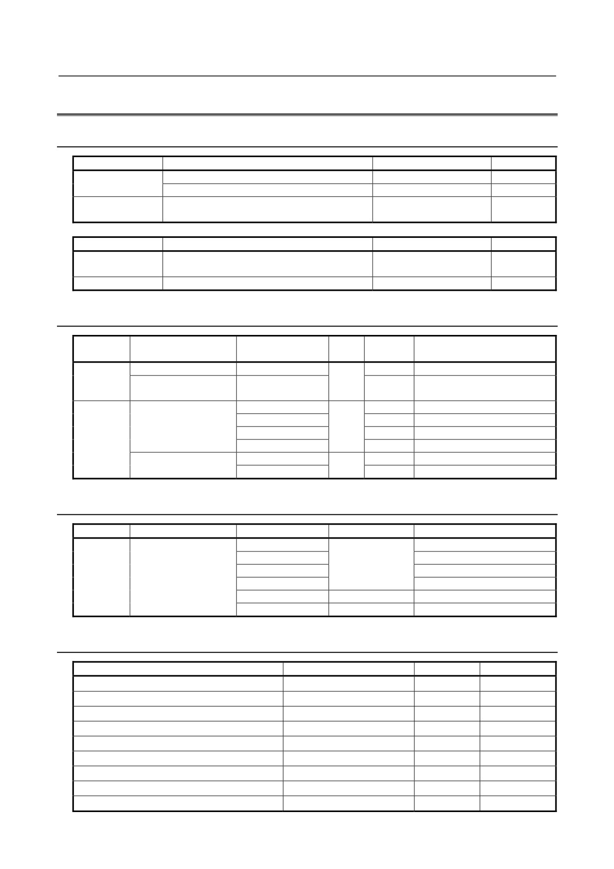
Inverter
Name
Specification
Inverter
For 8.4” color LCD
A20B-8002-0703
For 10.4” color LCD
A20B-8002-0702
Location of the inverter
Inverter
It is insde the cover.
Rear of unit
- 78 -
B-64305EN/03
2.LCD-MOUNTED TYPE CNC HARDWARE
2.5
LIST OF UNITS AND PRINTED CIRCUIT BOARDS
2.5.1
Basic Unit
CNC model
Name
Drawing number
Remarks
0i
Basic Unit (No slot)
A02B-0319-B500
Basic Unit (2 slots)
A02B-0319-B502
0i Mate
Basic Unit (No slot)
A02B-0321-B500
A02B-0321-B510
CNC model
Name
Drawing number
Remarks
0i
Cover Case (No slot)
A250-0921-X010
0i Mate
0i
Cover Case (2 slots)
A250-0921-X012
2.5.2
Display Unit
LCD
MDI
CNC model
Name
Drawing number
Remarks
ID
ID
0i
10.4” LCD unit
A02B-0319-D510
1010
10.4” LCD unit (with
A02B-0319-D511
touch panel)
0i
8.4” color LCD/MDI unit
A02B-0319-D514#T
1011
14
Horizontal- type MDI for T series
0i Mate
A02B-0319-D514#M
14
Horizontal- type MDI for M series
A02B-0319-D515#T
18
Vertical-type MDI for T series
A02B-0319-D515#M
18
Vertical-type MDI for M series
8.4” color LCD/MDI unit
A02B-0319-D518#T
1011
14
Horizontal-type MDI for T series
(with touch panel)
A02B-0319-D519#T
18
Vertical-type MDI for T series
2.5.3
MDI Unit
CNC model
Name
Drawing number
MDI ID
Remarks
0i
MDI unit (for 10.4” LCD
A02B-0319-C125#T
12
Horizontal- type MDI for T series
unit)
A02B-0319-C125#M
Horizontal- type MDI for M series
A02B-0319-C126#T
Vertical-type MDI for T series
A02B-0319-C126#M
Vertical-type MDI for M series
A02B-0303-C120#T
04
Small- type MDI for T series
A02B-0303-C120#M
08
Small- type MDI for M series
2.5.4
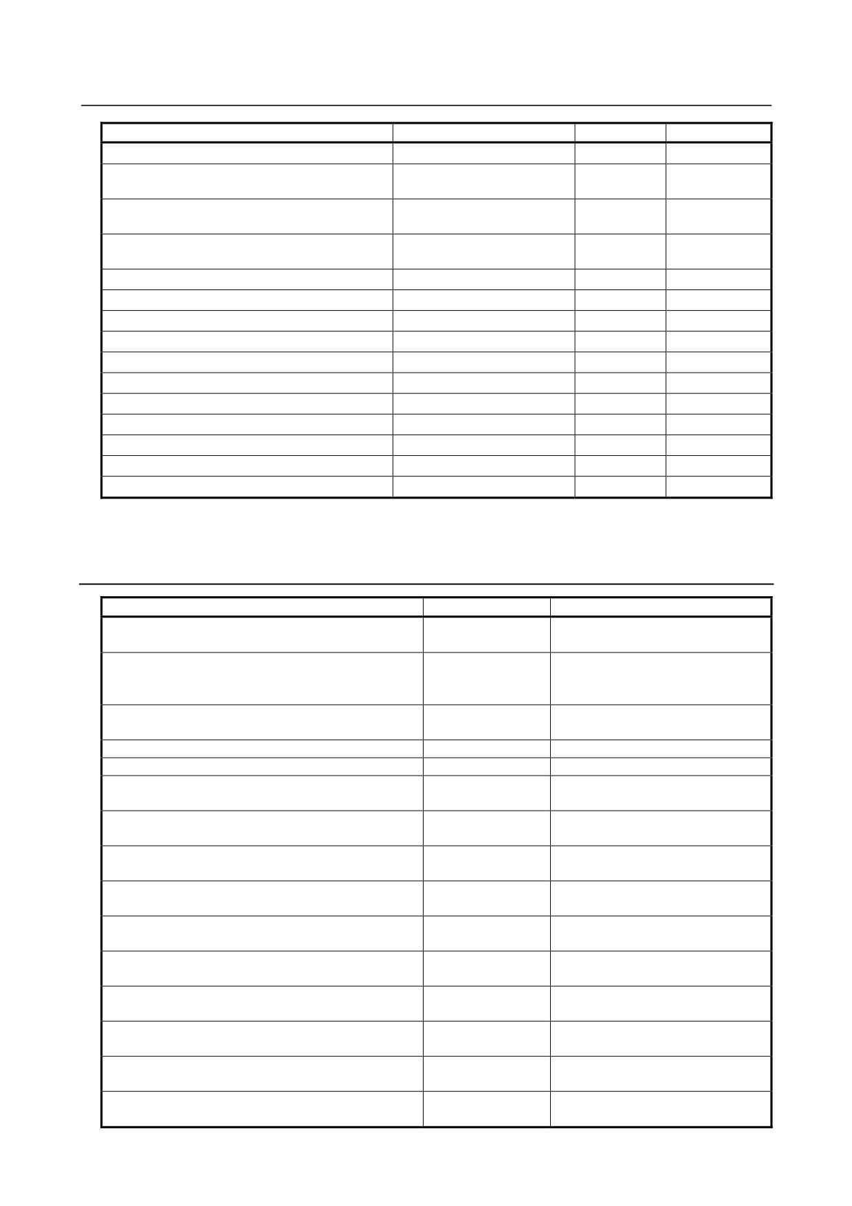
Printed Circuit Boards
Name
Drawing number
ID
Remarks
Main board A0
A20B-8200-0540
00428
Main board A1
A20B-8200-0541
00429
Main board A2
A20B-8200-0542
0042A
Main board A3
A20B-8200-0543
0042B
Main board A5
A20B-8200-0545
0042C
Axis card A1
A20B-3300-0635
00146
Axis card A2
A20B-3300-0638
0014B
Axis card A3
A20B-3300-0637
0014A
Axis card B2
A20B-3300-0632
0014D
- 79 -
2.LCD-MOUNTED TYPE CNC HARDWARE
B-64305EN/03
Name
Drawing number
ID
Remarks
Axis card B3
A20B-3300-0631
0014E
FROM/SRAM module A1
A20B-3900-0242
FROM: E3
(FROM 64MB, SRAM 1MB)
SRAM: 03
FROM/SRAM module B1
A20B-3900-0240
FROM: E4
(FROM 128MB, SRAM 1MB)
SRAM: 03
FROM/SRAM module B2
A20B-3900-0241
FROM: E4
(FROM 128MB, SRAM 2MB)
SRAM: 04
Fast Ethernet board
A20B-8101-0030
00701
PROFIBUS-DP master board
A20B-8101-0050
00704
PROFIBUS-DP slave board
A20B-8101-0100
00705
FL-net board
A20B-8101-0031
00702
DeviceNet master board
A20B-8101-0220
00706
DeviceNet slave board
A20B-8101-0330
00708
Power supply (0 slots)
A20B-8200-0560
01
Power supply (2 slots)
A20B-8200-0570
10
Inverter (for 8.4" color LCD)
A20B-8002-0703
-
Inverter (for 10.4" color LCD)
A20B-8002-0702
-
Touch panel control printed circuit board
A20B-8002-0312
-
* See Chapter
4,
“MATTERS COMMON TO BOTH
LCD-MOUNTED
TYPE
AND
STAND-ALONE TYPE (HARDWARE)” for optional boards.
2.5.5
I/O
Name
Drawing number
Remarks
I/O Unit for 0i
A02B-0309-C001
DI/DO: 96/64
with MPG interface
Distributed I/O operator’s panel I/O module A1
A20B-2002-0470
DI/DO: 72/56
DI=general 16, matrix 56, with MPG
interface
Distributed I/O operator’s panel I/O module B1
A20B-2002-0520
DI/DO: 48/32
A20B-2003-0750
with MPG interface
Distributed I/O operator’s panel I/O module B2
A20B-2002-0521
DI/DO: 48/32
Distributed I/O connector panel I/O basic module
A03B-0815-C001
DI/DO: 24/16
Distributed I/O connector panel I/O expansion module
A03B-0815-C002
DI/DO: 24/16
A
with MPG interface
Distributed I/O connector panel I/O expansion module
A03B-0815-C003
DI/DO: 24/16
B
Distributed I/O connector panel I/O expansion module
A03B-0815-C004
DO: 16 (2A output )
C
Distributed I/O connector panel I/O expansion module
A03B-0815-C005
Analog input
D
I/O module type-2 for connector panel: basic module
A03B-0815-C040
DI/DO:48/32
B1
with MPG interface
I/O module type-2 for connector panel: basic module
A03B-0815-C041
DI/DO:48/32
B2
without MPG interface
I/O module type-2 for connector panel: expansion
A03B-0815-C042
DI/DO:48/32
module E1
Terminal type I/O module: basic module
A03B-0823-C001
DI/DO:24/16
with I/O Link I/F
Terminal type I/O module: expansion module A
A03B-0823-C002
DI/DO:24/16
with MPG interface
Terminal type I/O module: expansion module B
A03B-0823-C003
DI/DO:24/16
without MPG interface
- 80 -
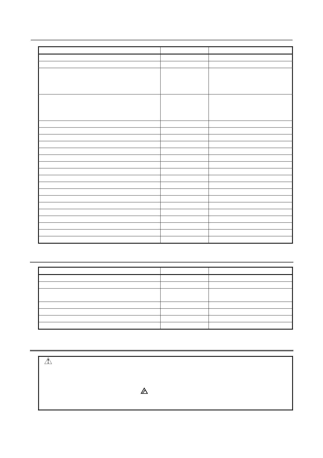
B-64305EN/03
2.LCD-MOUNTED TYPE CNC HARDWARE
Name
Drawing number
Remarks
Terminal type I/O module: expansion module C
A03B-0823-C004
DO: 16 (2A output )
Terminal type I/O module: expansion module D
A03B-0823-C005
Analog input
Main panel A machine operator's panel
A02B-0319-C242
Alphabetic MDI with keys labeled
in both alphabetic characters and
symbols; supporting simultaneous
push-down of 3 keys
Main panel B machine operator's panel
A02B-0319-C243
Keyboard labeled in both
alphabetic characters and
symbols; supporting simultaneous
push-down of 3 keys
Sub panel A machine operator's panel
A02B-0236-C232
Sub panel B machine operator's panel
A02B-0236-C233
Sub panel B1 machine operator's panel
A02B-0236-C235
Sub panel C machine operator's panel
A02B-0236-C234
Sub panel C1 machine operator's panel
A02B-0236-C236
Small machine operator's panel
A02B-0299-C152#M
Small machine operator's panel B
A02B-0309-C151#M
Operator's panel connector unit (Source type output A)
A16B-2202-0731
DI/DO: 64/32
Operator's panel connector unit (Source type output B)
A16B-2202-0730
DI/DO: 96/64
Handy machine operator's panel
A02B-0259-C221#A
Interface unit for handy machine operator's panel
A02B-0259-C220
I/O Link connected unit A
A20B-2000-0410
Electrical-optical
I/O Link connected unit B
A20B-2000-0411
Electrical-electrical
I/O Link connected unit C
A20B-2000-0412
Optical-optical
FANUC I/O Link-AS-i converter (For AS-I Ver.2.0)
A03B-0817-C001
FANUC I/O Link-AS-i converter (For AS-I Ver.2.1)
A03B-0817-C002
I/O Link distributed adapter (2ch)
A20B-1007-0680
I/O Link distributed adapter (3ch)
A20B-1008-0360
2.5.6
Other Units
Name
Drawing number
Remarks
Separate detector interface unit (basic 4 axes)
A02B-0303-C205
Separate detector interface unit (additional 4 axes)
A02B-0236-C204
Analog input separate detector interface unit (basic 4
A06B-6061-C201
axes)
Optical I/O Link adapter (standard type)
A13B-0154-B001
Optical I/O Link adapter (high-speed type)
A13B-0154-B004
Optical adapter
A13B-0154-B003
For serial spindle
Spindle distributed adapter
A13B-0180-B001
2.6
REPLACING THE MAIN BOARD
WARNING
Only those personnel who have received approved safety and maintenance
training may perform this replacement work.
When opening the cabinet and replacing the board, be careful not to touch the
high-voltage circuits (marked
and fitted with an insulating cover).
Touching the uncovered high-voltage circuits presents an extremely dangerous
electric shock hazard.
- 81 -
2.LCD-MOUNTED TYPE CNC HARDWARE
B-64305EN/03
CAUTION
Before replacing a printed circuit board, be sure to read Section 4.11,
“CAUTIONS IN REPLACING PCB’S,” to confirm the procedure.
Before starting replacement work, back up the contents (such as parameters
and programs) of the SRAM memory of the CNC. Otherwise, the contents of the
SRAM memory may be lost during replacement work. See Chapter 5, “INPUT
AND OUTPUT OF DATA” or Appendix C, “BOOT SYSTEM” for explanations
about how to save the contents of the SRAM memory.
Replacement procedure
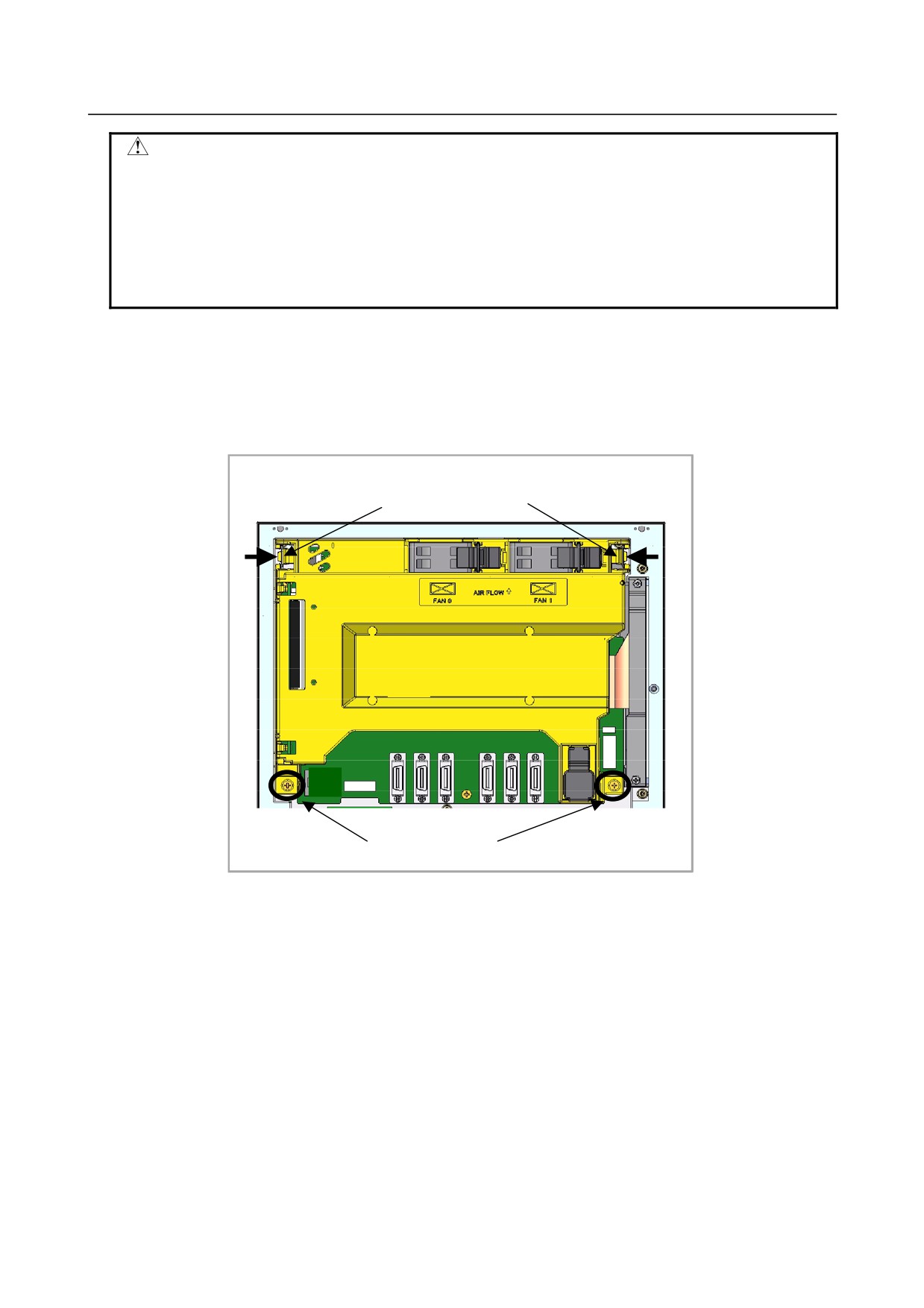
<1> Remove the 2 screws fastening the case.
(Before starting replacement, detach any cable from the option card.)
<2> Pull out the case while unlatching the claw from the base metal plate on either side of the upper
section of the case.
The case can be pulled out together with the back panel, fan, and battery attached to it.
<2> Pull out the case
while unlatching.
<2>
<2>
<1> Remove the screws.
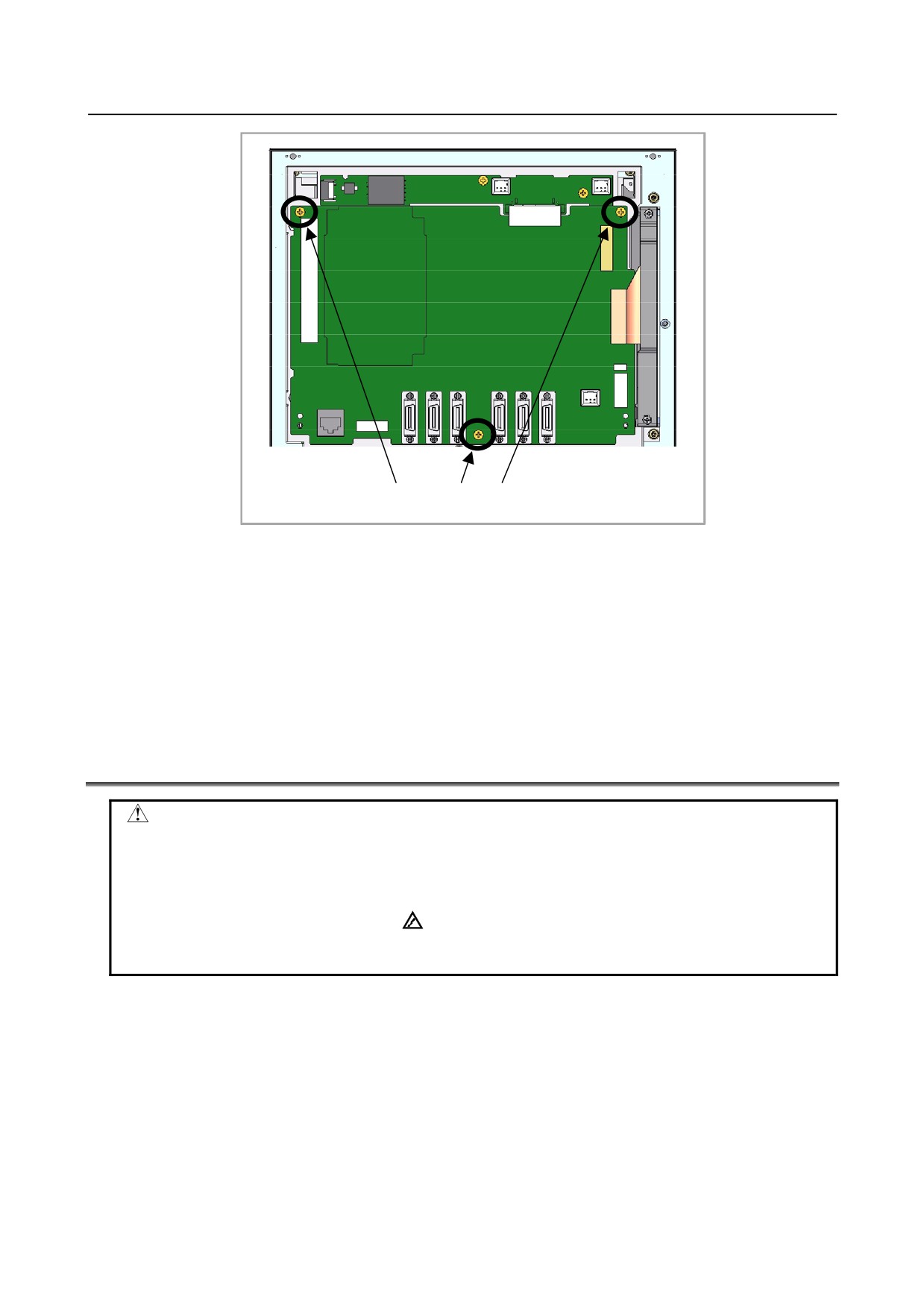
<3> Connectors on the main board
First, detach the cables from the following connectors:
CA88A (PCMCIA interface connector)
CA79A (video signal interface connector)
CA122 (connector for soft keys)
Next, remove the screws fastening the main board. The main board is connected directly to the
inverter PCB with connector CA121. So, slide down the main board when detaching it.
- 82 -
B-64305EN/03
2.LCD-MOUNTED TYPE CNC HARDWARE
CA121
CA79A
CA88A
CA122
<3> Remove the screws (3 places).
<4> Replace the main board.
<5> Align each cover screw with the corresponding latch, and slowly engage them with each other.
Attaching the cover causes the power supply printed circuit board on the cover to be connected to
the main board because their connectors are engaged with each other. Exercise caution so that no
excessive force is applied to the boards, and make sure that the connectors are attached to each other
securely.
<6> After confirming that the cover is latched securely, tighten the cover screws. Press down the fan
and battery lightly to confirm secure connection.
(Attach the option card cable if it has been
detached.)
2.7
REPLACING FUSE ON CONTROL UNIT
WARNING
Before replacing a blown fuse, locate and remove the cause of the blown fuse.
For this reason, only those personnel who have received approved safety and
maintenance training may perform this replacement work.
When opening the cabinet and replacing a fuse, be careful not to touch the
high-voltage circuits (marked
and fitted with an insulating cover).
Touching the uncovered high-voltage circuits presents an extremely dangerous
electric shock hazard.
- 83 -
2.LCD-MOUNTED TYPE CNC HARDWARE
B-64305EN/03
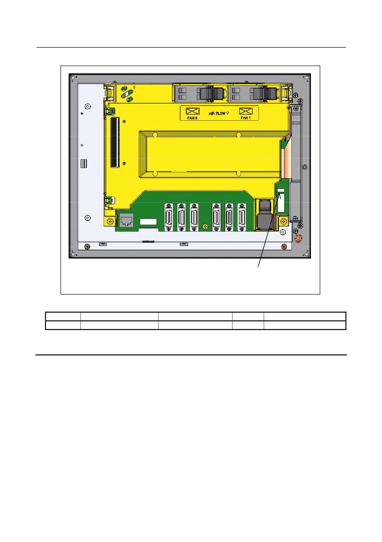
Fuse mounting location
FUSE1 (transparent)
for 24 VDC input
Fuse ordering information
Marking
Application
Ordering information
Rating
Individual specification
FUSE1
For 24 VDC power input
A02B-0236-K100
5A
A60L-0001-0290#LM50C
2.8
REPLACING BATTERY
Offset data, and system parameters are stored in SRAM in the control unit. The power to the SRAM is
backed up by a lithium battery mounted on the front panel of the control unit. The above data is not lost
even when the main battery goes dead. The backup battery is mounted on the control unit at shipping.
This battery can maintain the contents of memory for about a year.
When the voltage of the battery becomes low, alarm message "BAT" blinks on the display and the battery
alarm signal is output to the PMC. When this alarm is displayed, replace the battery as soon as possible.
In general, the battery can be replaced within two or three weeks, however, this depends on the system
configuration.
If the voltage of the battery becomes any lower, memory can no longer be backed up. Turning on the
power to the control unit in this state causes system alarm to occur because the contents of memory are
lost. Clear the entire memory and reenter data after replacing the battery.
FANUC thus recommends that the battery be replaced periodically, once a year, regardless of whether a
battery alarm is issued.
The following two kinds of batteries can be used.
• Lithium battery built into the CNC control unit.
• Two alkaline dry cells (size D) in the external battery case.
- 84 -
B-64305EN/03
2.LCD-MOUNTED TYPE CNC HARDWARE
NOTE
A lithium battery is installed as standard at the factory.
When a lithium battery is used
- Replacement procedure
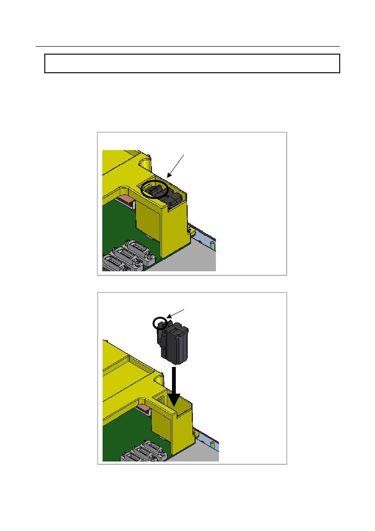
Prepare a new battery unit (ordering code: A02B-0309-K102).
(1) Turn on the power to the CNC. After about 30 seconds, turn off the power.
(2) Extract the old battery unit from the lower right of the rear of the CNC unit. (Hold the latch of the
battery unit, and extract the unit upward while releasing the claw from the case.)
Extract the unit while holding this portion.
(3) Mount the new battery unit. (Push the battery unit in until the claw is latched into the case.) Ensure
that the latch is engaged securely.
Push the unit in until the claw is
latched into the case.
- 85 -
2.LCD-MOUNTED TYPE CNC HARDWARE
B-64305EN/03
WARNING
Using other than the recommended battery may result in the battery exploding.
Replace the battery only with the specified battery (A02B-0309-K102).
CAUTION
Steps 1 to 3 should be completed within 30 minutes. Do not leave the control
unit without a battery for any longer than the specified period. Otherwise, the
contents of memory may be lost.
If steps 1 to 3 may not be completed within 30 minutes, save all contents of the
SRAM memory to the memory card beforehand. Thus, if the contents of the
SRAM memory are lost, the contents can be restored easily.
See Chapter 5, “INPUT AND OUTPUT OF DATA” or Appendix C, “BOOT
SYSTEM” for explanations about how to save the contents of the SRAM
memory.
When discarding a battery, observe the applicable ordinances or other rules of your local government.
In addition, cover the exposed pins with tape or other insulation materials to prevent a short circuit before
discarding the battery.
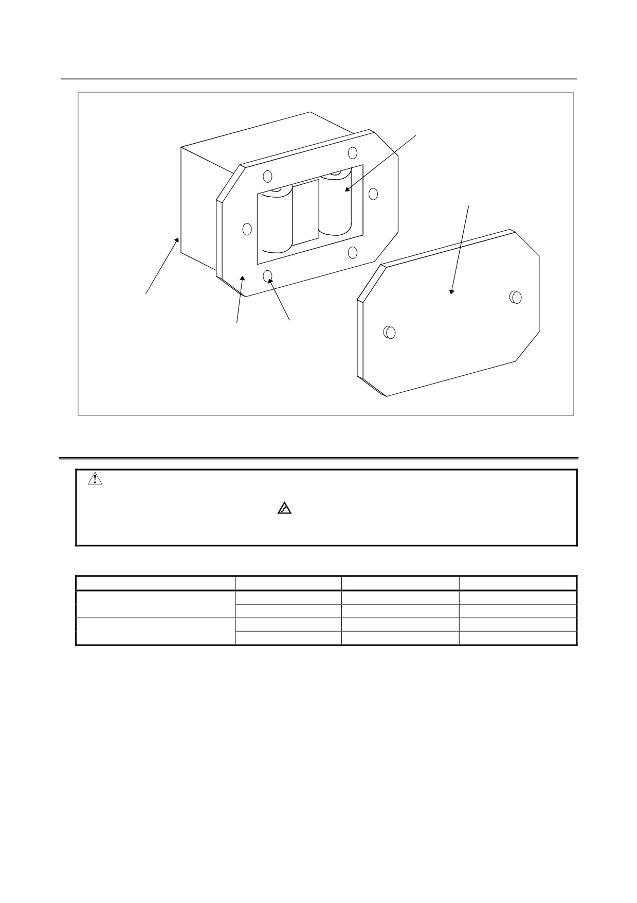
When alkaline dray cells (size D) are used
-
Replacing the battery
(1) Prepare two new alkaline dry cells (size D).
(2) Turn on the power of the control unit.
(3) Remove the battery case cover.
(5) Replace the batteries, paying careful attention to their orientation.
(6) Replace the battery case cover.
CAUTION
To replace the battery when the power is off, follow the same procedure as that
for the replacement of a lithium battery, described above.
- 86 -
B-64305EN/03
2.LCD-MOUNTED TYPE CNC HARDWARE
Dry cell × 2
Cover
Connection terminal
on the rear
Battery case
Mounting hole × 4
2.9
REPLACING FAN MOTORS
WARNING
When opening the cabinet and replacing a fan motor, be careful not to touch the
high-voltage circuits (marked
and fitted with an insulating cover).
Touching the uncovered high-voltage circuits presents an extremely dangerous
electric shock hazard.
-
Fan ordering information
Ordering code
Mounting location
Required quantity
A02B-0309-K120
FAN1(right)
1
Unit with no option slot
A02B-0309-K120
FAN0(left)
1
A02B-0309-K120
FAN1(right)
1
Unit with 1 slot or 2 option slots
A02B-0309-K121
FAN0(ft)
1
Replacement procedure
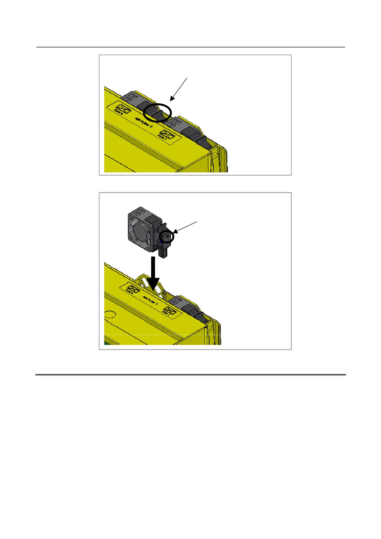
<1> Before replacing a fan motor, turn off the power to the CNC.
<2> Extract the fan motor to be replaced. (Hold the latch of the fan unit, and extract the unit upward
while releasing the claw from the case.)
- 87 -
2.LCD-MOUNTED TYPE CNC HARDWARE
B-64305EN/03
Extract the unit while holding this portion.
<3> Mount a new fan unit. (Push the fan unit in until the claw is latched into the case.)
Push the unit in until the claw is
latched into the case.
2.10 MOUNTING AND DEMOUNTING LCD/MDI UNIT
Some LCD units, MDI units and LCD/MDI units for this CNC are fastened with screws with M4 nuts
from the rear side; others are fastened with M3 screws from the front side. For some of the units
fastened from the front side, the screws are hidden under screw caps.
Unit fastened with M4 nuts from the rear side
•
8.4-inch color LCD/MDI unit
Units fastened with M3 screws from the front side
• MDI unit (vertical type or horizontal type) (without screw caps)
•
10.4-inch LCD unit (with screw caps)
•
MDI unit (small type) (with screw caps)
- 88 -
B-64305EN/03
2.LCD-MOUNTED TYPE CNC HARDWARE
2.10.1 Mounting or Demounting a 10.4” LCD Unit
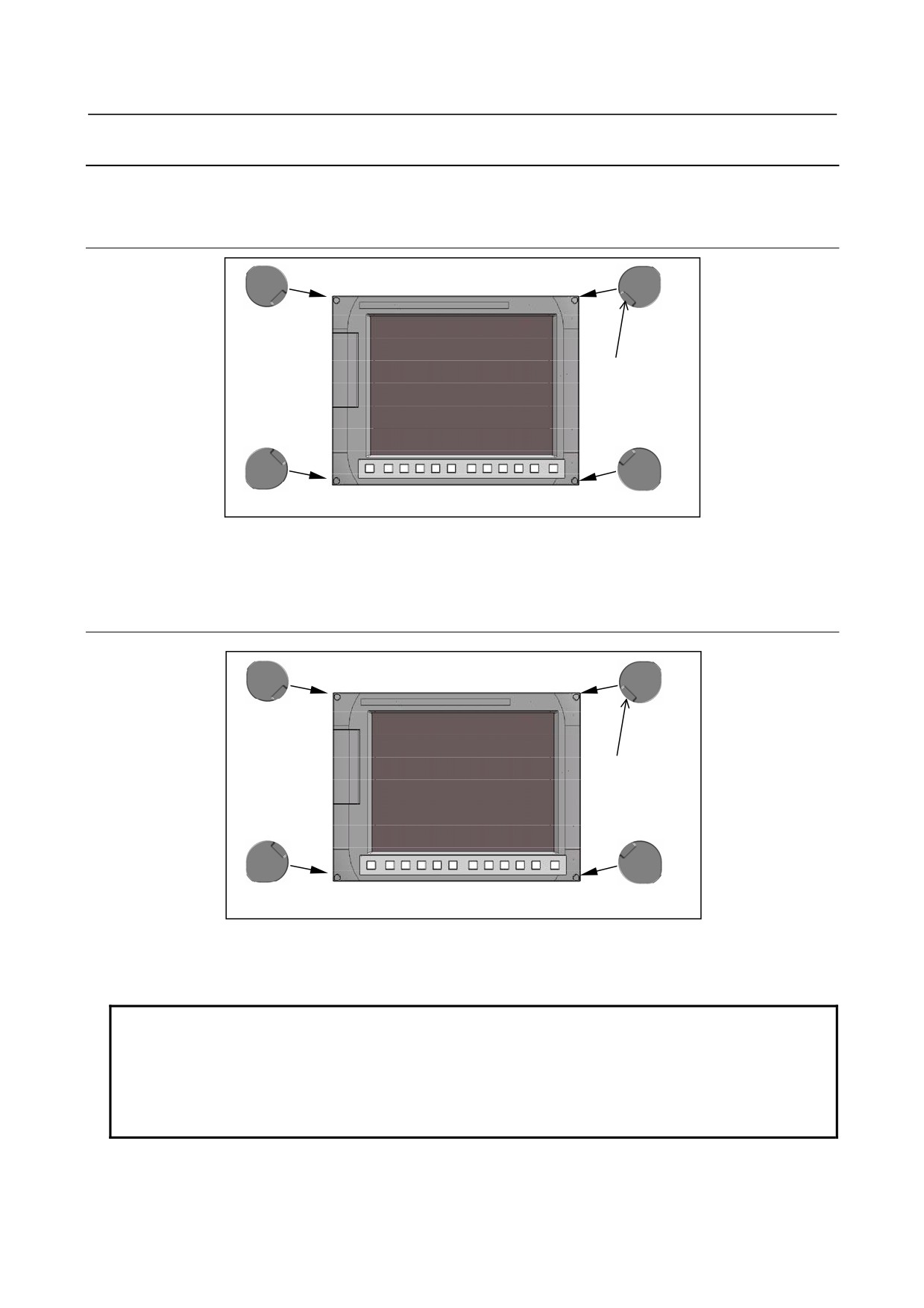
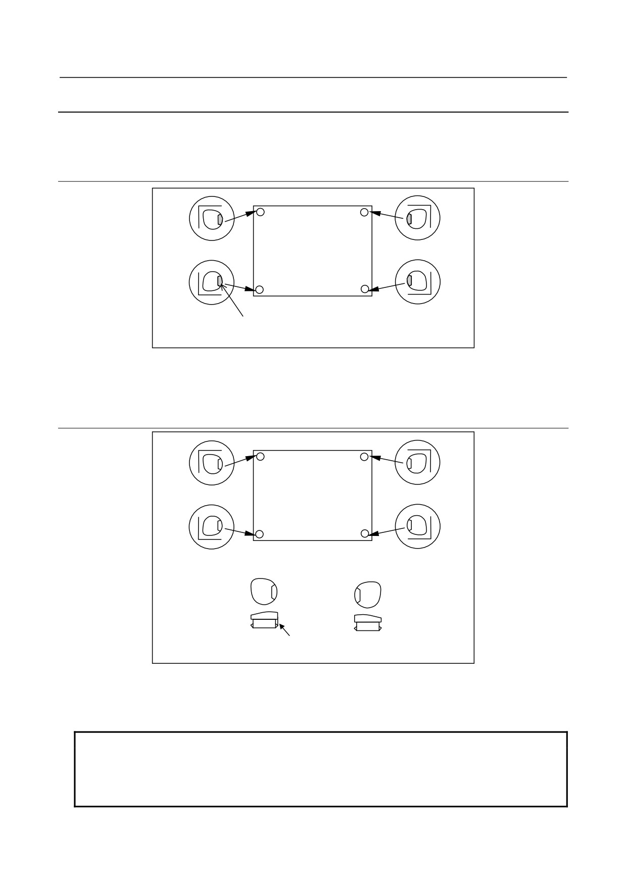
The 10.4” LCD unit is fastened with screws from the front side. They are hidden under screw caps.
2.10.1.1 Demounting
Dent
Screw caps (4 places)
<1> To remove a screw cap, insert the tip of a small flat-blade screwdriver or the like into the dent in it
and pull it out.
<2> To detach the unit, rotate each screw after the screw caps are removed.
2.10.1.2 Mounting
Dent
Screw caps (4 places)
<1> Fasten the unit at its four corners with screws.
<2> While paying attention to the orientation of each screw cap, push them in until their surfaces become
flush with the unit surface.
NOTE
In case a screw cap is lost or damaged, order replacements according to the
following ordering information.
A02B-0319-K190: Pack of 100 screw caps
A02B-0319-K191: Pack of 5 screw caps
- 89 -
2.LCD-MOUNTED TYPE CNC HARDWARE
B-64305EN/03
2.10.2 Mounting or Demounting an MDI Unit (Small Type)
The MDI unit (small type) is fastened with screws from the front side. They are hidden under screw
caps.
2.10.2.1 Demounting
Dent
Screw caps (4 places)
<1> To remove a screw cap, insert the tip of a small flat-blade screwdriver or the like into the dent in it
and pull it out.
<2> To detach the unit, rotate each screw after the screw caps are removed.
2.10.2.2 Mounting
B
A
B
A
A
B
Only A has a protrusion
(to distinguish A from B)
<1> Fasten the unit at its four corners with screws.
<2> There are two types of screw caps. Mount them as shown in the figure. While paying attention to
the orientation of each screw cap, push them in until their surfaces become flush with the unit
surface.
NOTE
In case a screw cap is lost or damaged, order replacements according to the
following ordering information.
A02B-0303-K190: A set of 100 type-A screw caps and 100 type-B screw caps
A02B-0303-K191: A set of 80 type-A screw caps and 100 type-B screw caps
- 90 -
B-64305EN/03
2.LCD-MOUNTED TYPE CNC HARDWARE
2.11 LIQUID CRYSTAL DISPLAY (LCD)
LCD with a touch panel
The touch panel is operated by directly touching the LCD screen. For this operation, be sure to use a
FANUC-supplied pen (A02B-0236-K111) dedicated to the touch panel. If a sharp-pointed pen is used, for
example, to touch the LCD screen, the LCD surface may be flawed or damaged. Moreover, do not touch
the LCD screen directly with a finger. Otherwise, the operability of the LCD
may deteriorate, and the LCD screen may get dirty.
Protection sheet for the touch panel
A protection sheet is attached the face of an LCD with a touch panel to protect the thin film of the touch
panel and LCD. If the protection sheet is damaged, it can be replaced. (The protection sheet is a
consumable part.)
Replacing the protection sheet
-
Materials used
(1)
Protection sheet
A02B-0309-K132 : For 8.4" LCD with touch panel
A02B-0236-K110 : For 10.4" LCD with touch panel
(2)
Neutral detergent (detergent that can clean oily dirt off = detergent for kitchen can be used)
(3)
Soft cloth (such as towel)
-
Replacement procedure
(1)
Before replacement
<1> Turn off the power to the machine.
<2> Peel off the old protection sheet from the surface of the touch panel.
<3> Wipe off adhesive residue if any on the screen surface with alcohol.
<4> Use the detergent to remove oil or dirt stuck to the surface of the touch panel.
<5> With a soft, damp cloth, wipe off detergent completely.
If the touch panel surface becomes cloudy, oil is still left on the surface. Remove oil
completely.
If oil or detergent is left on the surface of the touch panel, the protection sheet cannot
adhere to the panel completely and will sometimes peel off easily.
<6> With a dry soft cloth, wipe off moisture completely.
(2)
Applying the protection sheet
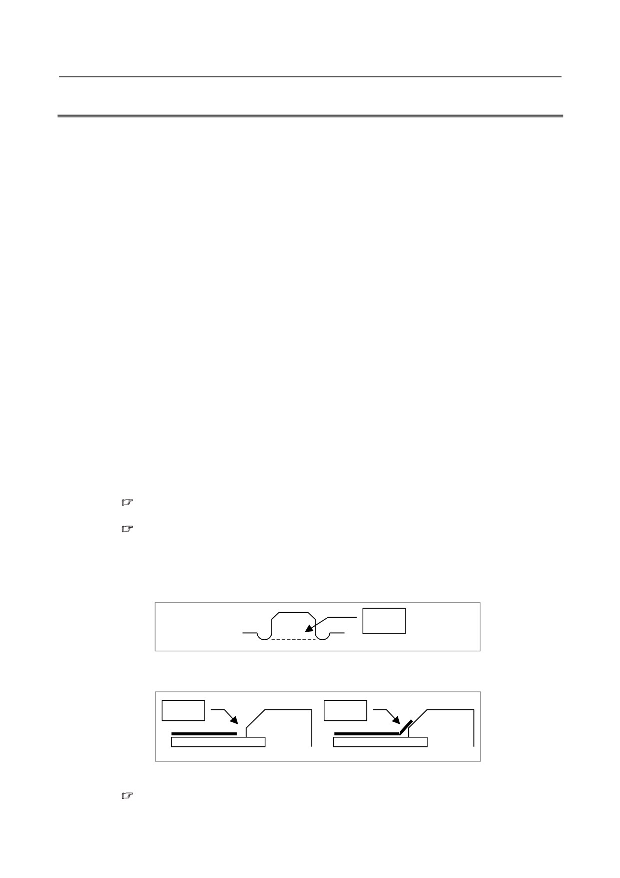
<1> Fold the tab over the front side (the side opposite to the backing sheet).
Fold
<2> Peel off the backing sheet.
<3> Position the sheet, then attach the upper and lower sides of the sheet first. Check that the sides
of the protection sheet do not touch the escutcheon.
OK
NG
<4> Attach the right and left sides of the protection sheet while pushing out air between the touch
panel and protection sheet.
With part of the protection sheet kept stuck to the touch panel, do not attempt to correct
the position of the protection sheet by pulling the sheet.
- 91 -
2.LCD-MOUNTED TYPE CNC HARDWARE
B-64305EN/03
<5> Press the adhesive parts of the four sides, and attach the entire sheet completely.
Check that the four corners and four sides of the protection sheet do not float.
(3) Checks after replacement
<1> Check that there is no wrinkle on the surface of the protection sheet.
<2> After power-on, check that there is no touch panel portion kept pressed.
<3> Press the touch panel, and check that correct operation takes place.
Touch panel calibration
-
Conditions that require calibration
Touch panel calibration is needed under the following conditions:
(1) The LCD unit was replaced.
(2) The touch panel was replaced.
(3) The touch panel control printed-circuit board was replaced.
(4) Memory all clear was performed.
-
Parameter
#7
#6
#5
#4
#3
#2
#1
#0
3113
DCL
[Input type] Parameter input
[Data type] Bit
# 5
DCL The touch panel compensation screen is:
0: Disabled.
1: Enabled.
Set this parameter to 0 usually. Touch panel compensation becomes necessary only when
the panel is replaced or memory all clear operation is performed. Set this parameter to 1
only when performing touch panel compensation. Upon completion of compensation, set
this parameter to 0.
-
Calibration method
Calibration procedure
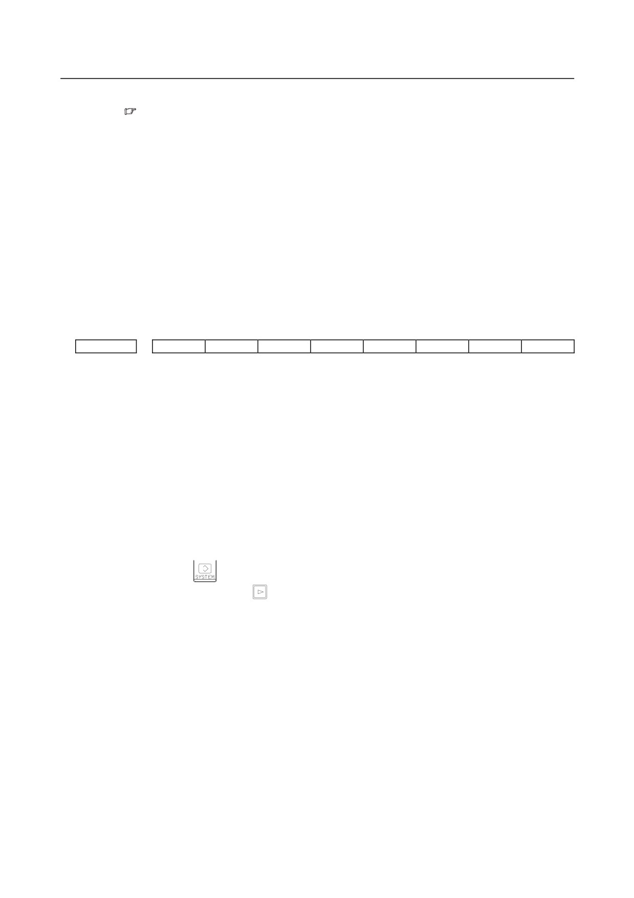
<1> Enable the touch panel calibration screen.(Set bit 5 (DCL) of parameter No. 3113 to 1.)
<2> Press function key
<3> Press the continuous menu key
several times. The [TOUCH PANEL] soft key is displayed.
- 92 -
B-64305EN/03
2.LCD-MOUNTED TYPE CNC HARDWARE
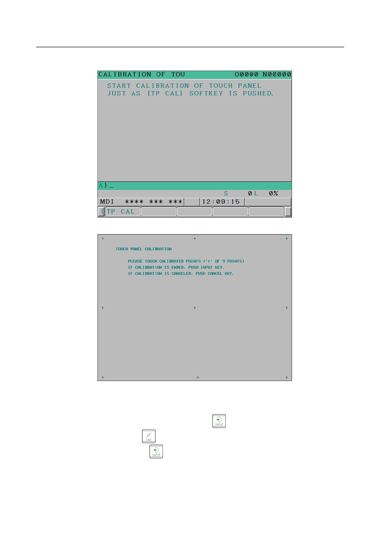
<4> Press the [TOUCH PANEL] soft key then the [(OPRT)] soft key. The [TP CAL] soft key is
displayed.
<5> Pressing the [TP CAL] soft key causes a full-screen touch panel calibration screen to appear.
<6> Click the 9 calibration points with a stylus pen. The marker of a normally clicked point changes
from "+" to "o". If you fail to click right on a "+" mark, the message "Your stylus pen is not right
on a "+" mark. Click again." appears.
<7> After clicking all 9 calibration points, clicking the
key completes calibration. To quit or
retry calibration, click the
key. The previous screen appears again. Before clicking 9
calibration points, clicking the
key aborts calibration.
<8> When calibration ends normally, the message "Calibration ended" appears.
<9> After completing calibration, disable the touch panel calibration screen (by resetting the bit 5 (DCL)
of parameter No. 3113 to 0) to prevent operation mistake.
- 93 -
3.STAND-ALONE TYPE CNC SERIES HARDWARE
B-64305EN/03
3 STAND-ALONE TYPE CNC SERIES
HARDWARE
The FANUC Series 0i-D of the stand-alone type is a CNC whose control and display units are separated.
(The FANUC Series 0i Mate-D of the stand-alone type is not provided.) For the stand-alone type Series
0i -D, the FANUC PANEL i or a commercially available IBM PC compatible personal computer is used
as a display unit. A CNC consisting of a control unit incorporated display unit is called the
LCD-mounted type and a CNC whose control and display units are separated is called the stand-alone
type below.
This chapter describes the functions of the stand-alone type CNC control unit printed circuit boards and
card PCBs on the printed circuit boards as well as how to replace consumables.
For the maintenance of the FANUC PANEL i, refer to the FANUC PANEL i Connection and
Maintenance Manual (B-64223EN).
- 94 -
B-64305EN/03
3.STAND-ALONE TYPE CNC SERIES HARDWARE
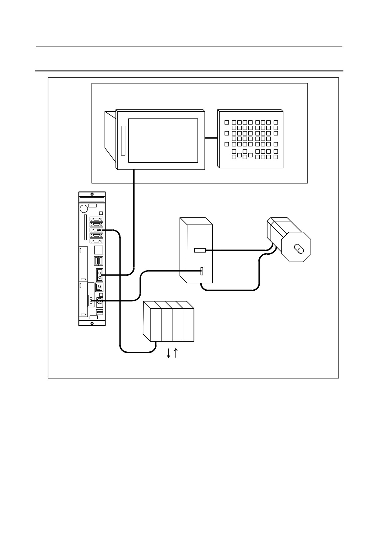
3.1
HARDWARE CONFIGURATION
Display unit
PANEL i or commercially available personal computer
(An HSSB board is required for a commercially
MDI unit
available personal computer.)
(The MDI unit can be connected only to the
PANEL i.)
Control unit
Servo motor
Servo amplifier
Optical cable
Distributed I/O, I/O unit MODEL-A
I/O Link
Machine operator's panel, power magnetic circuit, etc.
- 95 -
3.STAND-ALONE TYPE CNC SERIES HARDWARE
B-64305EN/03
3.2
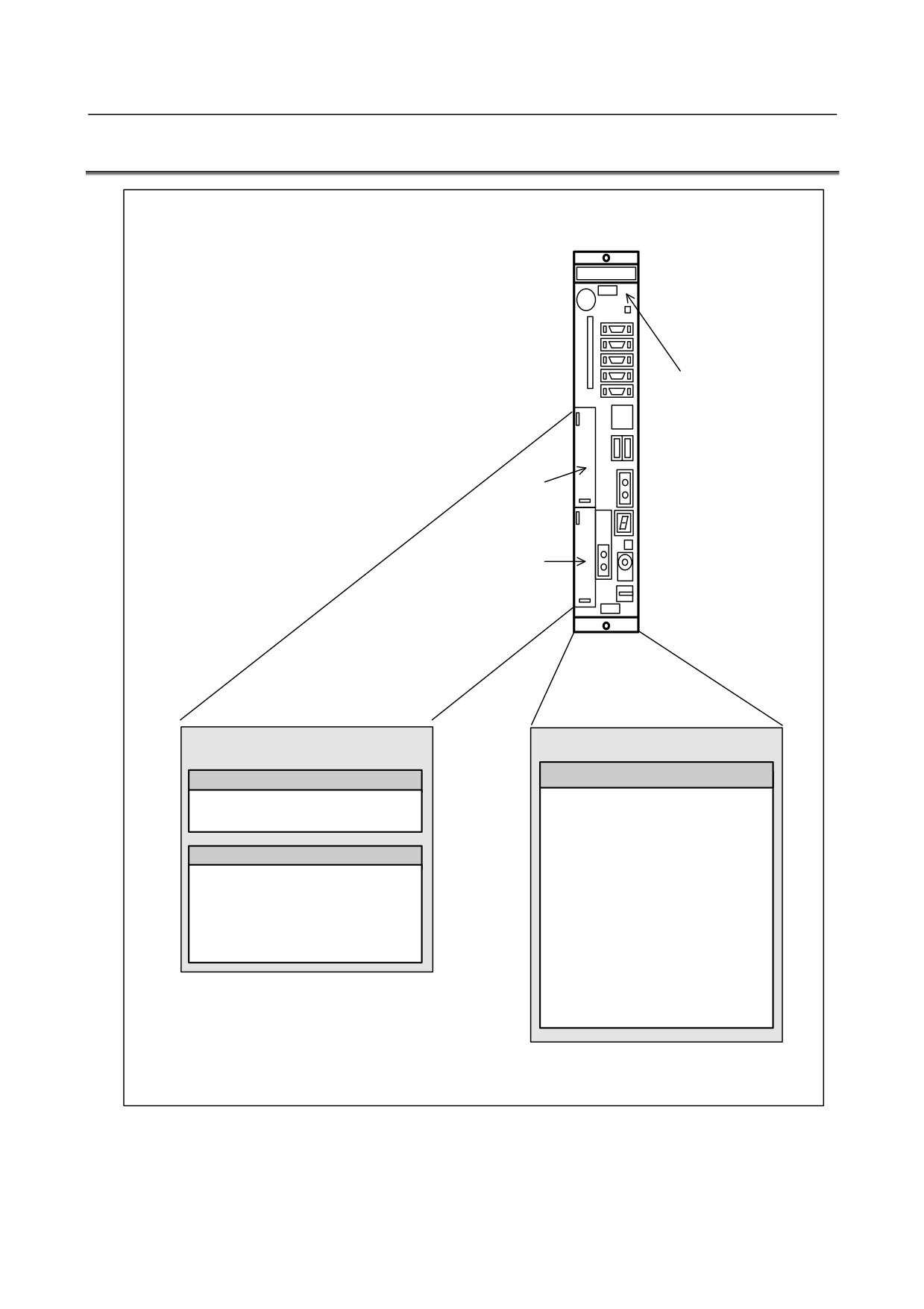
HARDWARE OVERVIEW
2-slot rack
Main board
Slot 1
Slot 2
Option (slot 1 to 2)
Basic system
Main board
Fast Ethernet board
Data server function
• CPU for controlling CNC
Ethernet communication function
• Power supply
• Axis control
Various types of network boards
• Spindle interface
PROFIBUS-DP master board
• DISPLAY interface
PROFIBUS-DP slave board
• I/O Link
FL-net board
• PMC control function
DeviceNet master board
• High-speed DI
DeviceNet slave board
• RS-232C
• Memory card interface
• Ethernet
- 96 -
B-64305EN/03
3.STAND-ALONE TYPE CNC SERIES HARDWARE
3.3
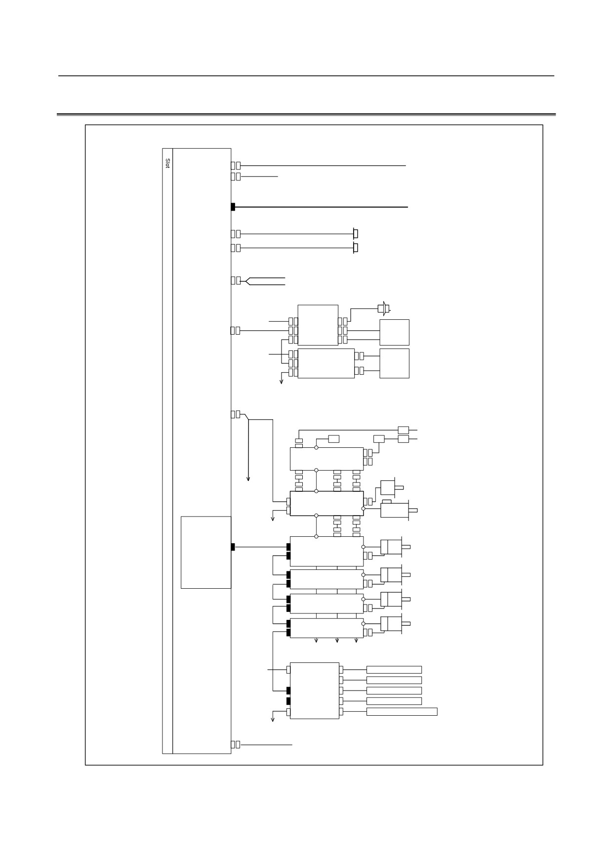
TOTAL CONNECTION DIAGRAMS
Main board
24V-IN(CPD19A)
24 VDC power supply
24V-OUT(CPD19B)
To I/O device
Optical fiber ccable
PANEL i or personal
DISPLAY(COP21A)
computer
R232-1(JD36A)
RS-232-C I/O device
R232-2(JD36B)
RS-232-C I/O device
Analog putput for tool drive
A-OUT&HDI(JA40)
High-peed skip input
Distributed
Manual pulse generator
I/O board
24VDC
CPD1
JA3
I/O Link(JD51A)
JD1B
Operator's
panel
JD1A
24VDC
CPD1
Distributed
Power
JD1B
I/O board,
magnetics
I/O unit,
JD1A
cabinet
etc.
SPDL(JA41)
Circuit breaker
200VAC
AC reactor
200VAC
MCC
Circuit breaker
αi PS
Position coder
3rd spindle
αi SP
Servo card
To 2nd spindle
Serial spindle motor
Optical fiber cable
FSSB(COP10A-1)
COP10B
Axis 1
αi SV
servo motor
COP10A
Axis 2
COP10B
αi SV
servo motor
COP10A
Axis 3
COP10B
αi SV
servo motor
COP10A
Axis 4
COP10B
αi SV
servo motor
COP10A
(In this figure, a 1-axis amplifier is used.)
Separate detector interface unit 1
24VDC
CP11A
JF101
Linear scale, axis 1
JF102
Linear scale, axis 2
COP10B
JF103
Linear scale, axis 3
COP10AJF104
Linear scale, axis 4
CNF1
JA4A
Battery for absolute scale
(Required only when an absolute scale is used)
Separate detector
interface unit 2
ETHERNET(CD38A)
Ethernet
- 97 -
3.STAND-ALONE TYPE CNC SERIES HARDWARE
B-64305EN/03
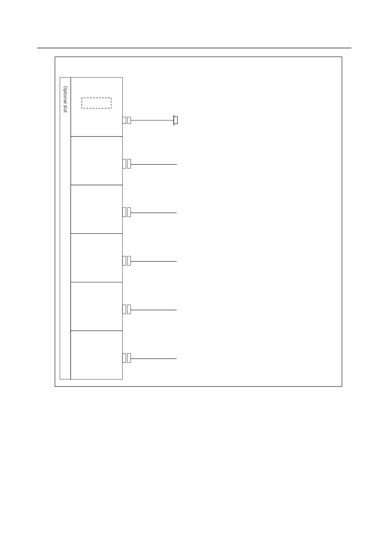
When optional functions are provided
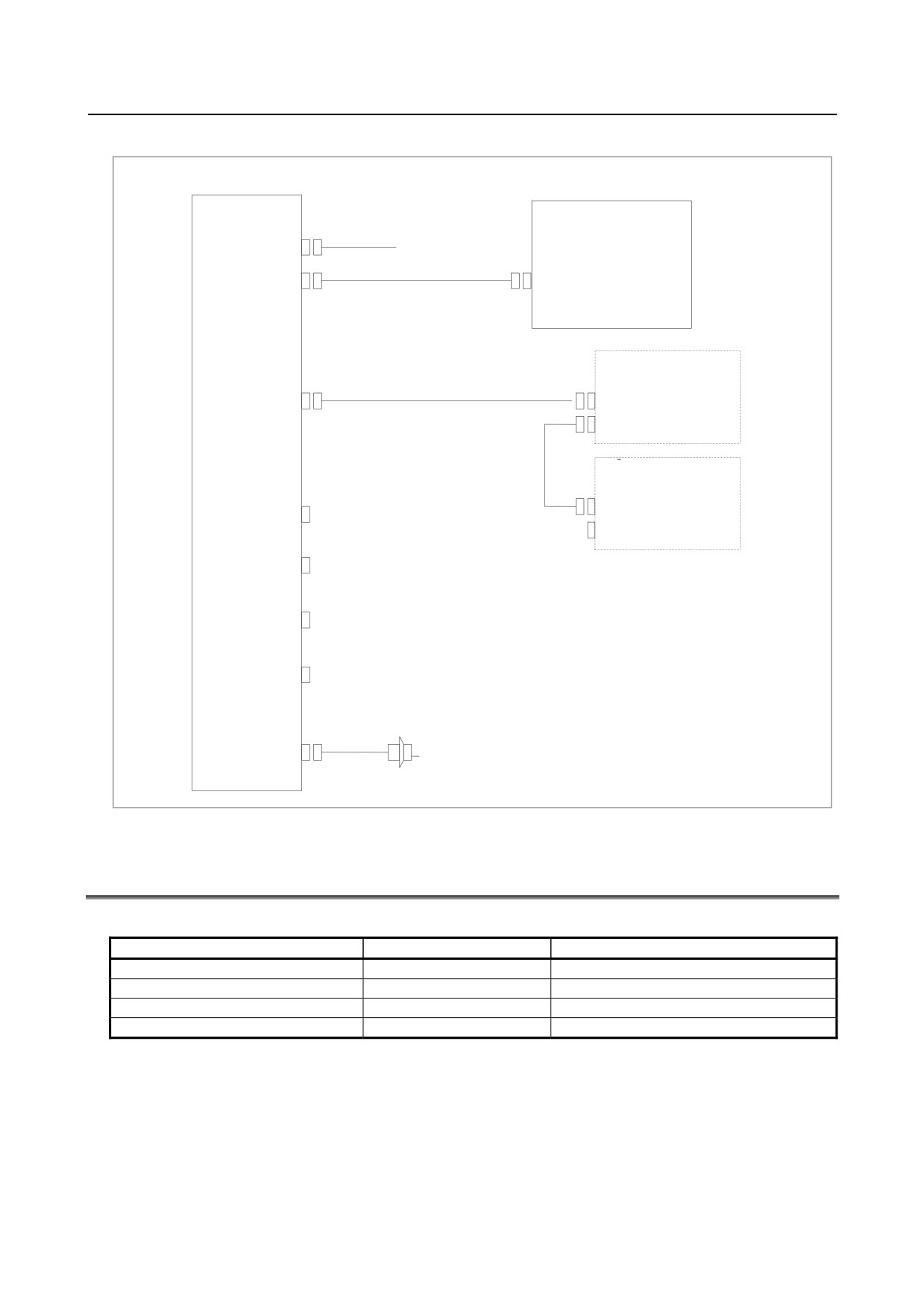
Fast Ethernet board
Memory card
Prepare the memory card recommended by FANUC.
ETHERNET(CD38R)
Ethernet
PROFIBUS-DP
master board
PROFI(CN1)
Another NC or Profibus
device
PROFIBUS-DP
slave board
PROFI(CN2)
Another NC or Profibus
device
DeviceNet
master board
DVNET(TBL)
Another NC or DeviceNet
device
DeviceNet
slave board
DVNET(TBL)
Another NC or DeviceNet
device
FL-net board
FLNET(CD38N)
FL-net device
- 98 -
B-64305EN/03
3.STAND-ALONE TYPE CNC SERIES HARDWARE
Connection example to I/O Link
For Series 0i
I/O Unit for 0i
Series 0i
main board
(CP1)
DC24V
I/O Link (JD1B)
JD51A
I/O for operator’s
I/O Link
panel
I/O Link (JD1A)
JD1B
JD1A
DI : 96 points
DO : 64 points
I/O Link βi
servo amplifier
DI/DO-1
JD1B
(CB104)
JD1A
DI/DO-2
(CB105)
The order in which slave devices are
connected via I/O Link can be
DI/DO-3
determined freely.
(CB106)
DI/DO-4
(CB107)
MPG(JA3)
Manual pulse generator (up to 3 units)
3.4
CONFIGURATION OF PRINTED CIRCUIT BOARD
CONNECTORS AND CARDS
・Main board specification
Item
Model
Ordering code
Main board B0
0i
A16B-3200-0700
Main board B1
0i
A16B-3200-0701
Main board B2
0i
A16B-3200-0702
Main board B3
0i
A16B-3200-0703
- 99 -
3.STAND-ALONE TYPE CNC SERIES HARDWARE
B-64305EN/03
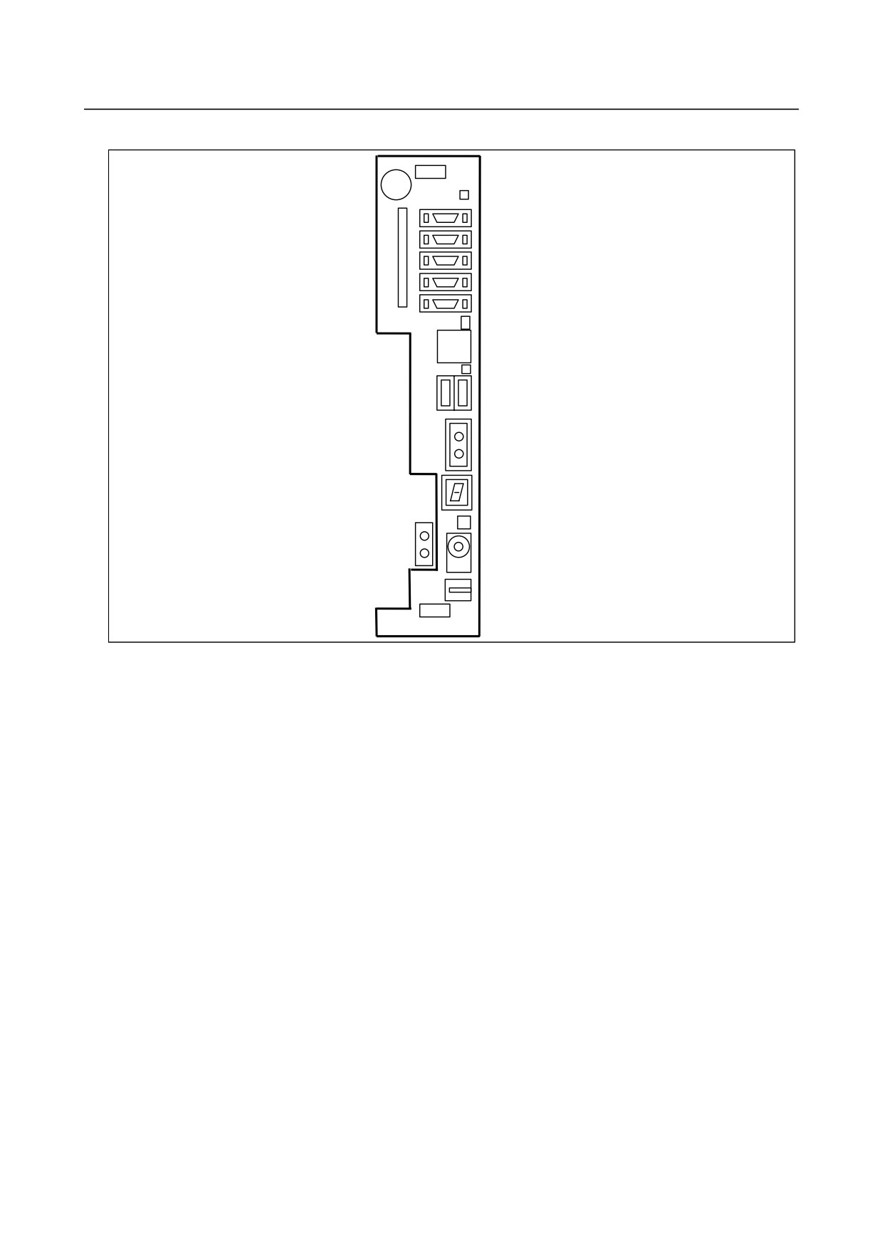
・Mounting positions of connectors, LEDs, etc.
Battery case
BAT1 : Battery
JD36A : RS-232-C serial port 1
JD36B : RS-232-C serial port 2
CNM1B : Memory card
JD51A : I/O Link
JA40 : Analog spindle / High-speed DI
JA41 : Serial spindle / Position coder
LINK,COM : LED for embedded Ethernet
CD38A : Embedded Ethernet
FUSE ALM : Fuse burn-out detection LED
CPD19A(right) : 24VDC IN
CPD19B(left) : 24VDC OUT
COP21A : Connection to display unit
STATUS : 7-Segment LED
ALARM : Alarm LED
COP10A-1 : FSSB
MTSW : Rotary SW
PSW : Push SW
GND : SG connection terminal
STATUS 7-segment LED:
This LED usually indicates the state of the CNC. This LED is used also for setting and maintenance
using the rotary switch MTSW and the push switch PSW.
MTSW rotary switch:
This rotary switch is used for setting and maintenance operations, in combination with the STATUS
7-segment LED and the PSW push switch.
PSW push switch:
This push switch is used for setting and maintenance operations, in combination with the STATUS
7-segment LED and the MTSW rotary switch.
- 100 -
B-64305EN/03
3.STAND-ALONE TYPE CNC SERIES HARDWARE
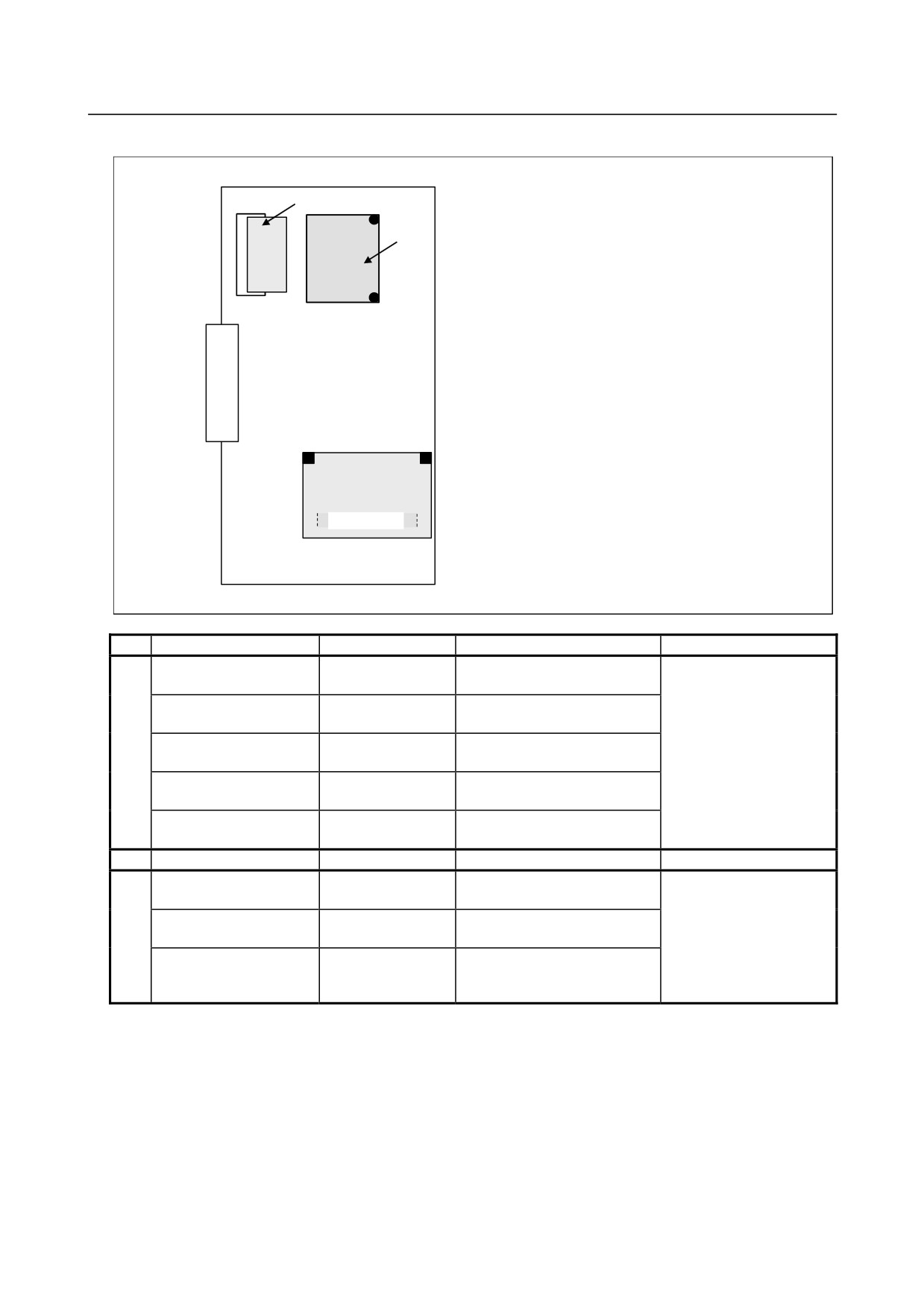
・Mounting positions of cards and DIMM modules
(3) FROM/SRAM module
(2) Power supply
(1) Axis card
No.
Item
Ordering code
Function
Remarks
(1)
Axis card A1
A20B-3300-0635
Path 1 control, supporting up to
The maximum number of
2 axes
axes is also limited
Axis card A2
A20B-3300-0638
Path 1 control, supporting up to
depending on the model.
4 axes
Axis card A3
A20B-3300-0637
Path 1 control, supporting up to
5 axes
Axis card B2
A20B-3300-0632
Path 2 lathe control, supporting
up to 6 axes
Axis card B3
A20B-3300-0631
Path 2 lathe control, supporting
up to 8 axes
(2)
Power supply
A20B-8101-0011
(3)
FROM/SRAM module A1
A20B-3900-0242
FROM 64MB
The FROM stores various
SRAM 1MB
control software programs,
FROM/SRAM module B1
A20B-3900-0240
FROM 128MB
user software programs,
SRAM 1MB
and so forth.
FROM/SRAM module B2
A20B-3900-0241
FROM 128MB
The SRAM is a
SRAM 2MB
battery-backed memory
module.
- 101 -
3.STAND-ALONE TYPE CNC SERIES HARDWARE
B-64305EN/03
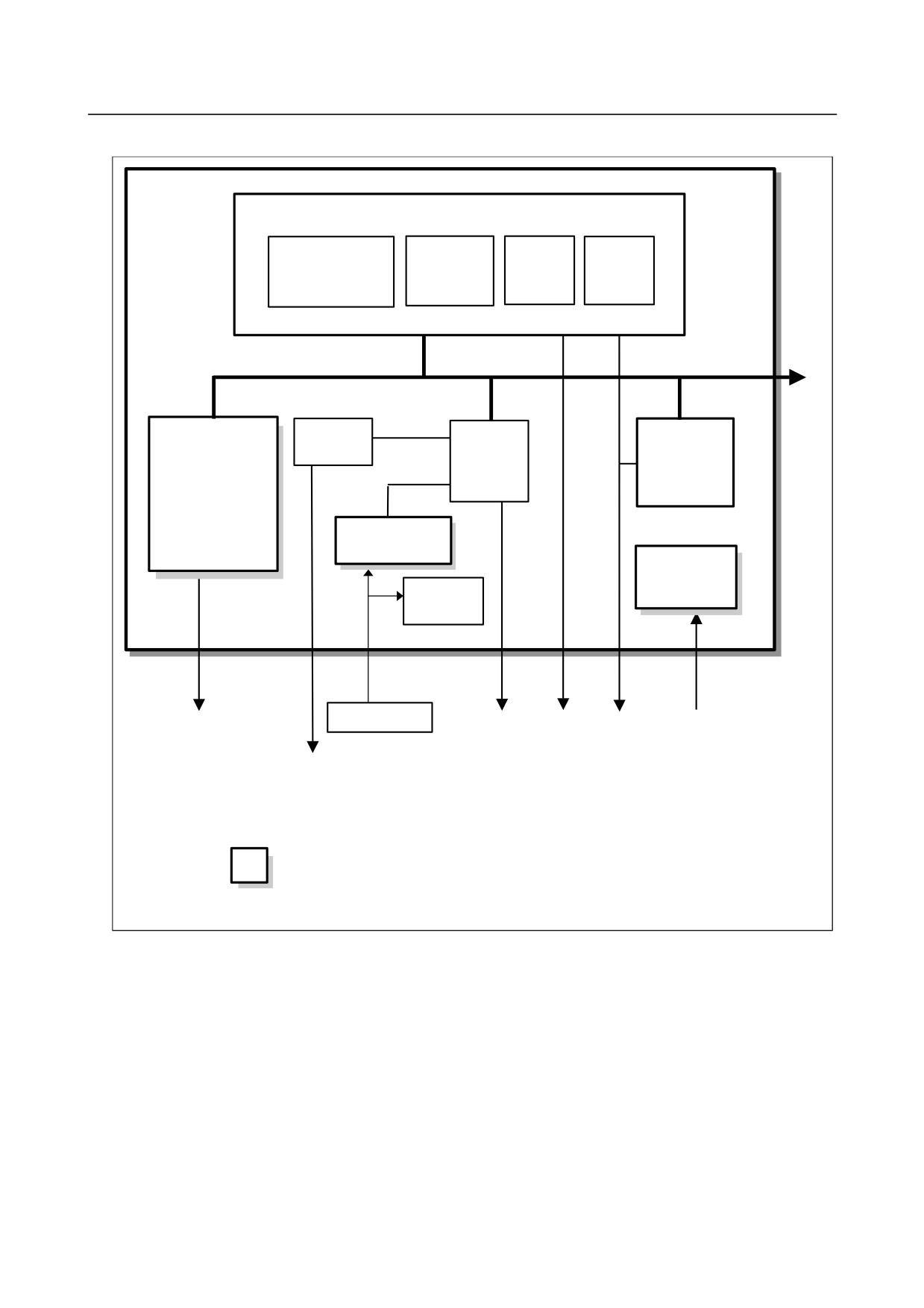
・Block diagram
Main board
CPU circuit
CPU
Main
BOOT
I/O Link
memory
software
control
To back panel
Axis card
Display
Peripheral
PMC control
control
control
I/O Link
control
DIMM module
FROM/SRAM
Power
supply
Calendar
function
Lithium battery
FSSB
MDI
Ethernet
I/O Link
24VDC
3V
RS-232-C
Memory card
Display unit
Serial spindle
HDI
:
Detachable card or module
- 102 -
B-64305EN/03
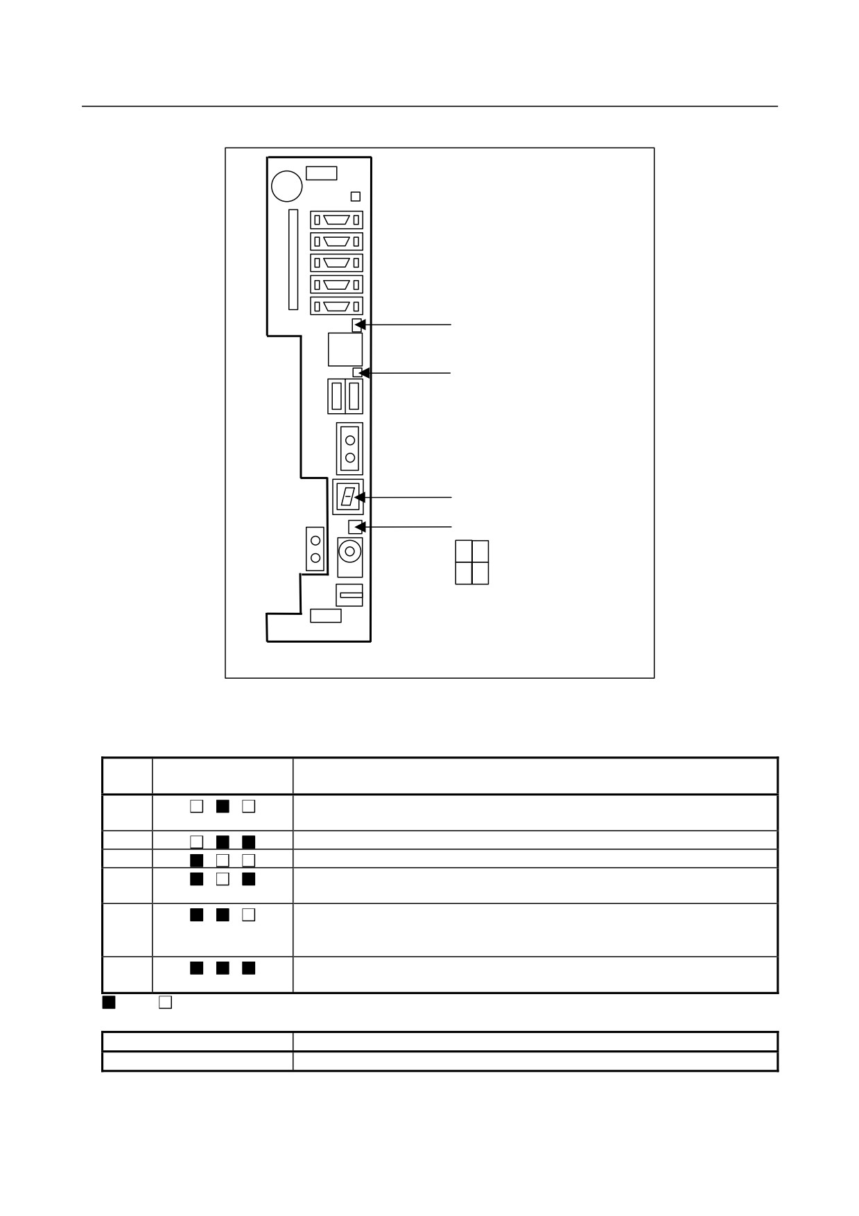
3.STAND-ALONE TYPE CNC SERIES HARDWARE
・LED display
LED for embedded Ethernet
LINK
(Upper, green)
COM
(Lower, yellow)
FUSE ALM : Fuse burn-out detection
LED
STATUS : 7-Segment LED
ALARM : Alarm LED
1
4
2
3
(1) Alarm LED (red) display when a system alarm occurs
If any of these LEDs lights, it is likely that the hardware is defective.
Alarm LED
No.
Meaning
3
2
1
1
Low battery voltage.
The battery may be running out.
2
Software detected an error and stopped the system.
3
Hardware detected a failure in the system.
4
An alarm was issued with the servo card on the main board.
The servo card or servo amplifier may be faulty, or the FSSB may be broken.
5
An error was detected in the data of the SRAM on the DIMM module.
The DIMM module may be faulty, the battery voltage may have dropped, or the
main board may be faulty.
6
Abnormal power supply operation.
The cause may be noise or a power supply failure.
: On
: Off
Alarm LED
Meaning
4 (LOW)
The main board (CPU circuit) may be faulty.
- 103 -