FANUC SERVO AMPLIFIER a series. DESCRIPTIONS (B-65162E/03) - page 18
B-65162E/03
11. OPTION RELATED TO SPINDLE
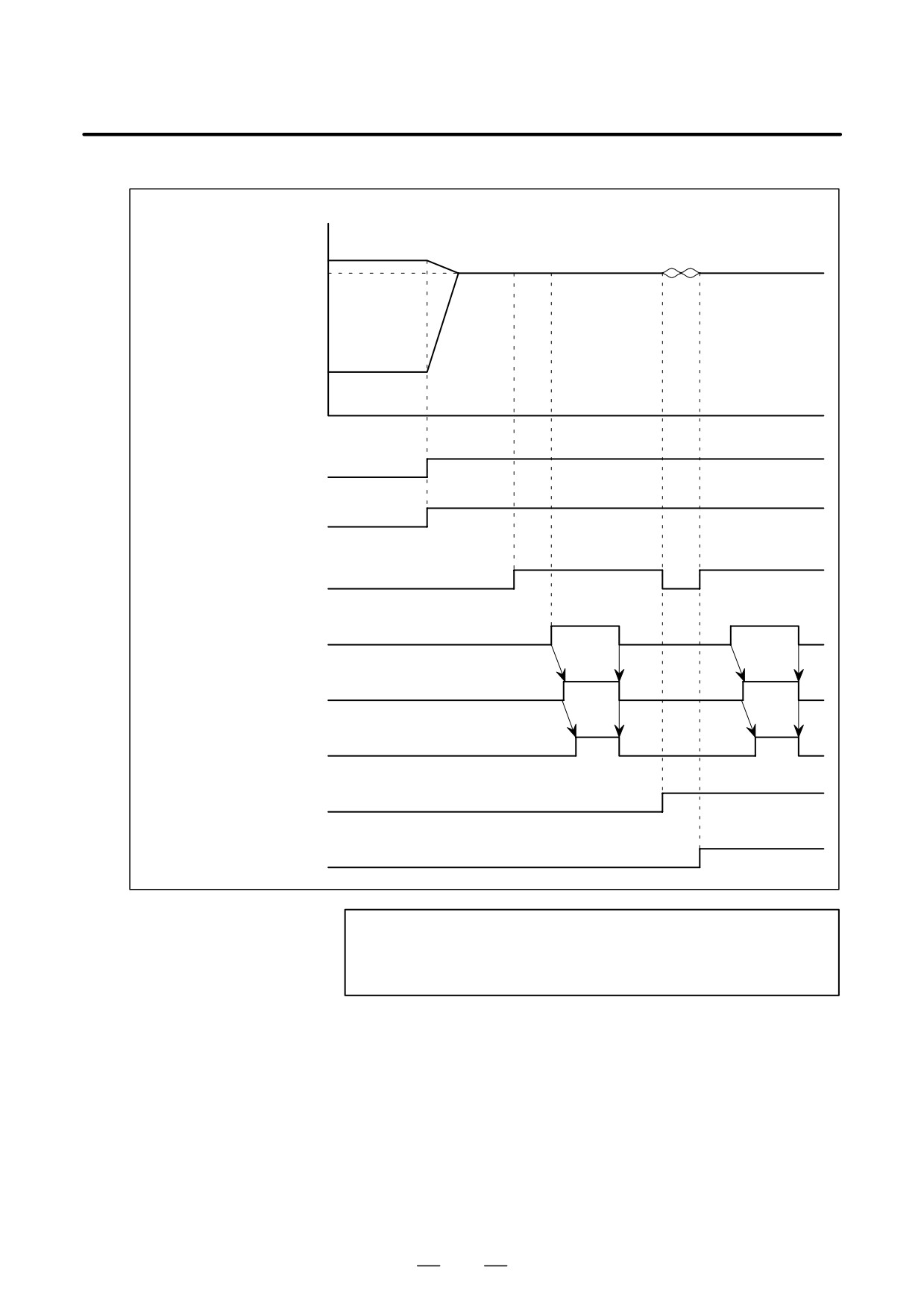
D Using the signal for integral speed control
Spindle speed
Spindle 1
Phase synchronization
Synchronization speed
Spindle 2
Signal for spindle synchronization
control SPSYC
Signal for specifying spindle
synchronization speed
Signal indicating that synchronization control
of spindle speed is completed
FSPSY
Signal for the chuck close command
Signal indicating that the chuck has been closed
Signal for integral speed control
INTCA
(Note)
(Note)
Signal for spindle phase synchronization control
SPPHS
Signal indicating that synchronization control of spindle phase is completed
FSPPH
NOTE
Set the signal for integral speed control to
1 while a
workpiece is being held with the two spindles.
513
11. OPTION RELATED TO SPINDLE
B-65162E/03
11.4.6
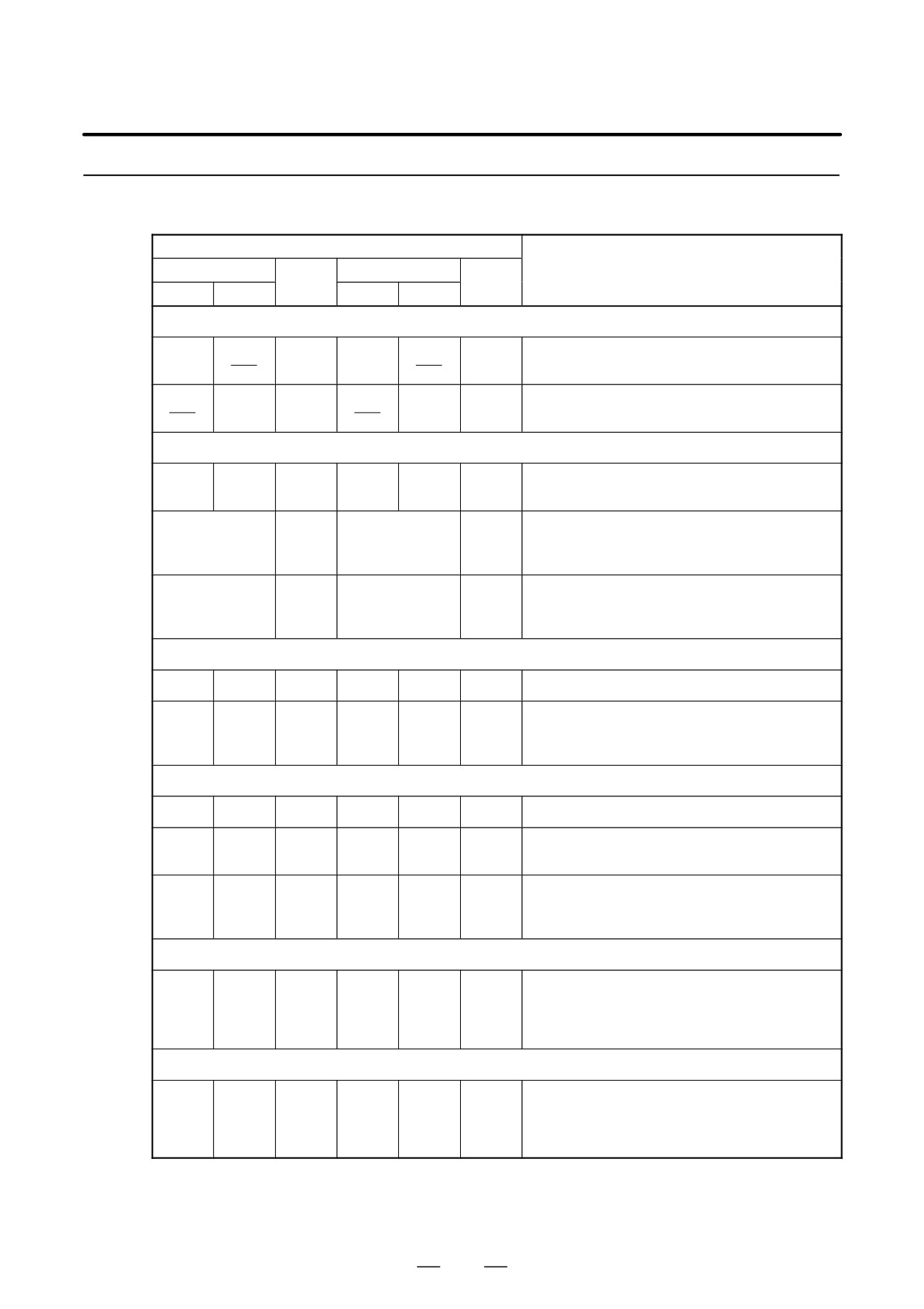
The tables below list the parameters related to spindle synchronization
control. Refer to the Parameter Manual and each CNC manual for details.
Parameters
Parameter No.
FS0
FS15-TT
Description
FS0-TT
FS16
1st
2nd
1st
2nd
Rotation direction setting
Rotational direction of spindle motor for spindle
0080#6
0086#6
5820#0
4800#0
synchronization control (1st spindle)
Rotational direction of spindle motor for spindle
0080#7
0080#6
5820#1
4800#1
synchronization control (2nd spindle)
Setting related to output signals for spindle synchronization
Target level for the spindle speed synchronization
6533
6673
6533
3033
3173
4033
control
Difference between error pulses for the two
0303
0303
5810
4810
spindles, regarded as spindle phase synchroniza-
tion completion signal
Difference between error pulses for the two
0576
0576
5811
4811
spindles, regarded as an alarm during spindle syn-
chronization control
Setting of gear ratio data between the spindle and motor
6506#1
6646#1
6506#1
3006#1
3146#1
4006#1
Increment system for gear ratios
Gear ratio between the spindle and motor
6556 to
6696 to
6556 to
3056 to
3196 to
4056 to
(selected by DI signals CTH1A and CTH2A from
6559
6699
6559
3059
3199
4059
the PMC)
Setting related to a shift amount and phase synchronization
6534
6674
6534
3034
3174
4034
Shift for spindle phase synchronization control
Compensation data for spindle phase synchro-
6535
6675
6535
3035
3175
4035
nization control
Setting to disable automatic one-rotation signal
6506#3
6646#3
6506#3
3006#3
3146#3
4006#3
detection when the spindle synchronization mode
is switched
Position gain setting
Position gain for spindle synchronization control
6565 to
6705 to
6565 to
3065 to
3205 to
4065 to
(The same value must be set for both spindles.)
6568
6708
6568
3068
3208
4068
(selected by DI signals CTH1A and CTH2A from
the PMC)
Setting of acceleration/deceleration time constants
Acceleration/deceleration time constant for spindle
synchronization control
6532
6672
6532
3032
3172
4032
(The same value must be set for the 1st and 2nd
spindles.)
514
B-65162E/03
11. OPTION RELATED TO SPINDLE
Parameter No.
FS0
FS15-TT
Description
FS0-TT
FS16
1st
2nd
1st
2nd
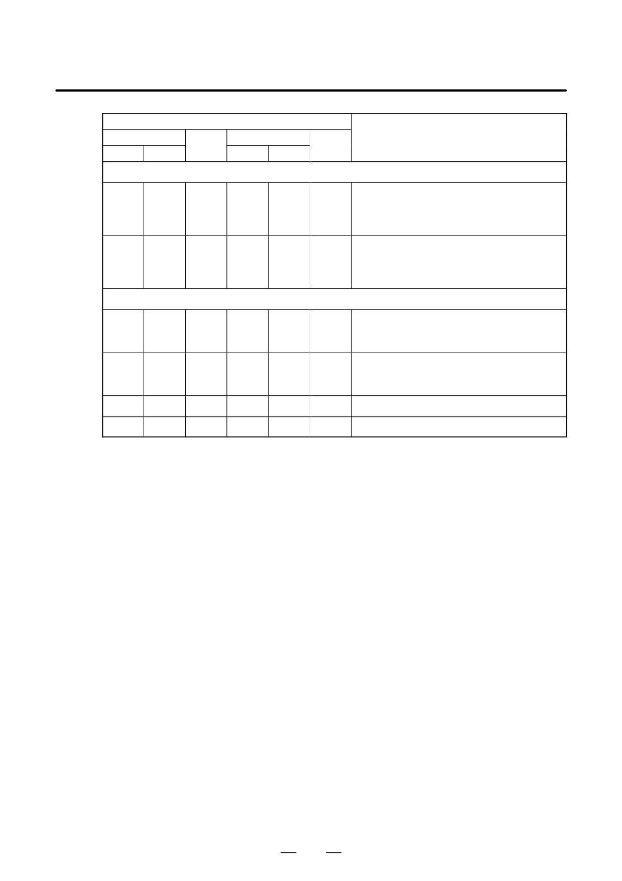
Setting of acceleration/deceleration time constants (Continued)
Flux switching point for calculating the accelera-
tion/deceleration time constant for spindle syn-
6300
6480
6300
3480
3700
4336
chronization control
(The same value must be set for both spindles.)
Bell-shaped acceleration/deceleration
time
constant for spindle synchronization control
6304
6484
6304
3484
3704
4340
(The same value must be set for the 1st and 2nd
spindles.)
Setting of a velocity loop gain and motor voltage
Velocity loop proportional gain for spindle synchro-
6544
6684
6544
3044
3184
4044
nization control
6545
6685
6545
3045
3185
4045
(selected by DI signal CTH1A from the PMC)
Velocity loop integral gain for spindle synchroniza-
6552
6692
6552
3052
3192
4052
tion control
6553
6693
6553
3053
3193
4053
(selected by DI signal CTH1A from the PMC)
6585
6725
6585
3085
3225
4085
Motor voltage for spindle synchronization control
6310
6490
6310
3490
3710
4346
Incomplete integral coefficient
515
11. OPTION RELATED TO SPINDLE
B-65162E/03
11.5
SPEED RANGE
SWITCHING
CONTROL
Speed range control conducts switching of speed range in one motor
11.5.1
(motor designed specifically for speed range switching control) using the
General
FANUC SERVO AMPLIFIER α series SPINDLE AMPLIFIER
MODULE.
NOTE
This function is not available for αC series.
11.5.2
Configuration and
Order Drawing
Number
Configuration
The following items are needed in addition to the spindle amplifier
module.
D Speed range switching control software (option)
D Relay circuit (including electromagnetic contactor and drive relay)
D Switching signal from PMC
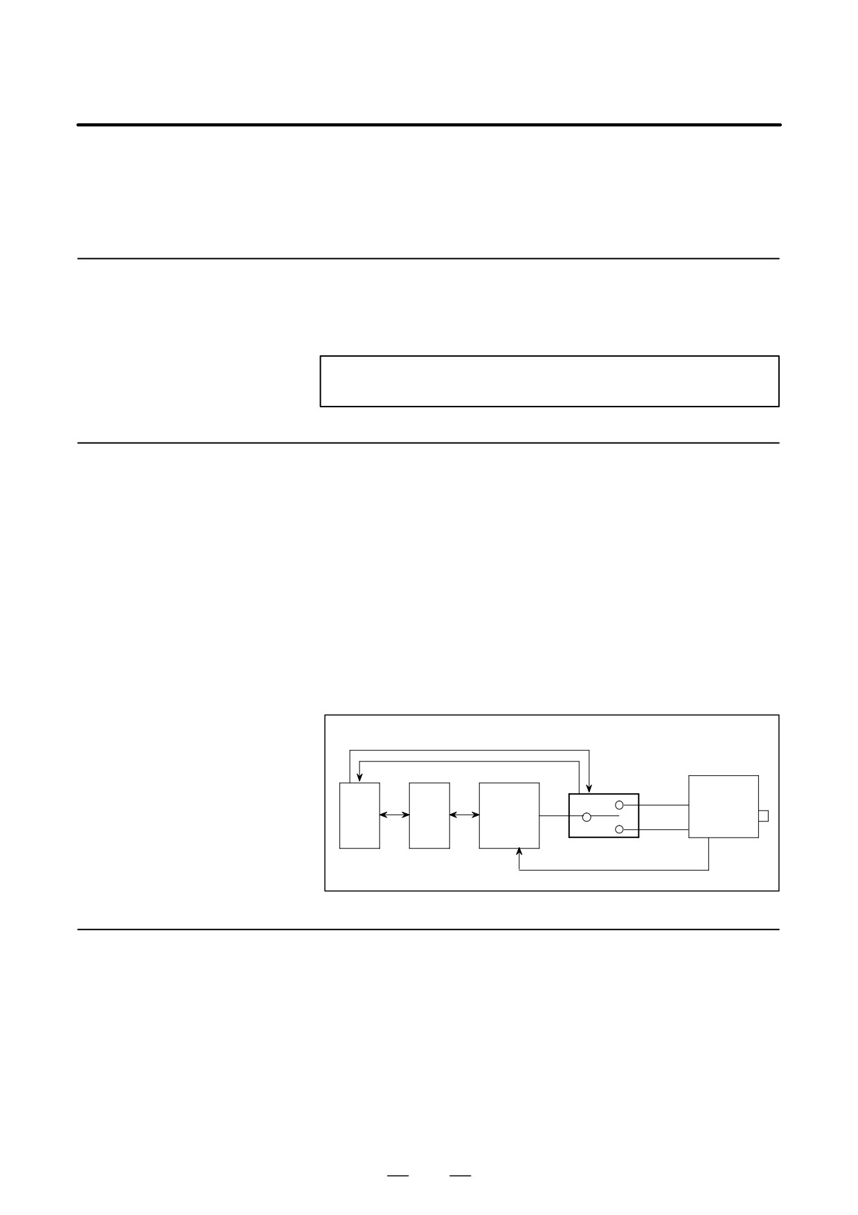
Configuration of the components is shown in following fig.
Speed range switching signal
Status confirmation signal
Switching unit
Spindle
Spindle
motor with
Power
PMC
CNC
amplifier
speed range
line
(SPM)
switching
Feedback signal
11.5.3
D On a spindle motor with the output switch function, the user can switch
Specifications
between two types of windings: one for the low-speed output
characteristics and the other for the high-speed output characteristics.
Switching is possible even while the motor is rotating.
D A spindle amplifier (SPM) is usable regardless of its type.
D To check the status of the power line, check the statuses of the
magnetic contactors for both high-speed range and low-speed range.
This function can be selected by the parameter setting:
516
B-65162E/03
11. OPTION RELATED TO SPINDLE
FS16
:
No. 4014 #3=1
FS15
:
No. 3014 #3=1
FS0
:
No. 6514 #3=1
D As the speed detecting signal (SDTA) is used for switching speed
detection, it cannot be used for gear change speed detection, etc.
D As the error detection function for switching operation, the alarm
(AL-15) is issued if the magnetic contactor signal
(RCHA,
RCHHGA) is not applied within 1 second of the power line switch
signal (RCHPA) being output.
11.5.4
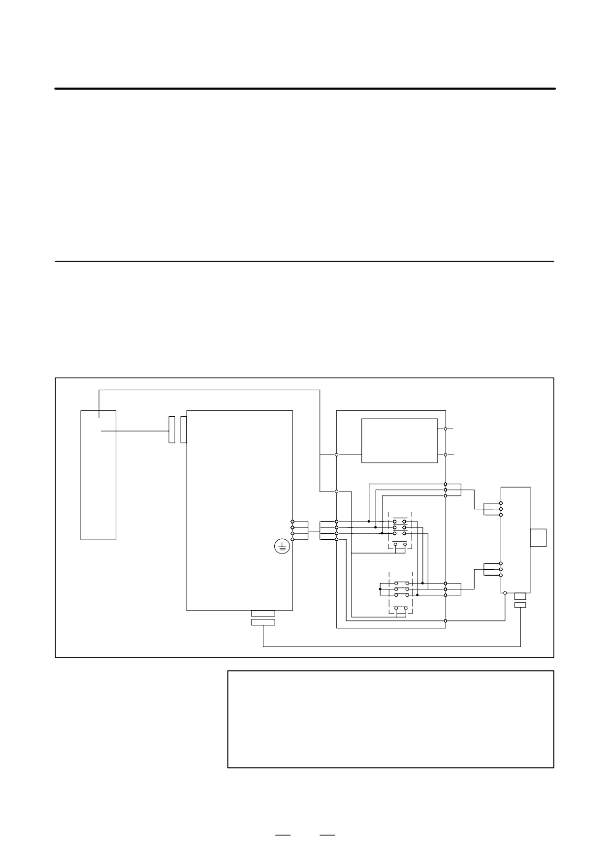
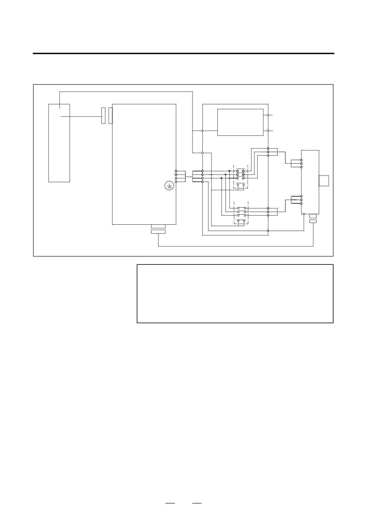
The connections of Type A and Type B, below, depend on the
specification of a spindle motor with the output switch function. When
Connections
low-speed output characteristics mode is selected, MCC1 is on, and
MCC2 is off. When high-speed output characteristics mode is selected,
MCC1 is off, and MCC2 is on.
(1) Type A
Relay circuit
Communica-
tion cable
JA7B
Electromagnetic
contactor switching
Single phase
circuit
200VAC
AC
CNC
Spindle amplifier
Electromagnetic contactor
spindle
module (SPM)
for switching power cable
U
motor
and
V
PMC
W
U
TB2
MCC 2
V
U
U
W
V
V
W
ÂÂ
Auxilially
G
contact
ÂÂ
X
MCC1
Y
X
Z
Y
G
Z
Auxilially
JY2
contact
G
NOTE
The power supply module is omitted from the figure.
Items such as units and cables other than the spindle
amplifier module and, AC spindle motor, which are
surrounded by the unbroken line, must be provided by the
machine tool builder.
517
11. OPTION RELATED TO SPINDLE
B-65162E/03
(2) Type B
Relay circuit
Communica-
tion cable
JA7B
Electromagnetic
contactor switching
Single phase
circuit
200VAC
AC
CNC
Spindle amplifier
Electromagnetic con-
spindle
module (SPM)
tactor for switching
U2
motor
and
power cable
V2
PMC
W2
U2
TB2
MCC 2
V2
U
W2
V
W
Auxilially
contact
ÂÂ
U1
MCC 1
V1
U1
W1
V1
G
W1
Auxilially
JY2
contact
NOTE
The power supply module is omitted from the figure.
Items such as units and cables other than the spindle
amplifier module and, AC spindle motor, which are
surrounded by the unbroken line, must be provided by the
machine tool builder.
518
B-65162E/03
11. OPTION RELATED TO SPINDLE
(3)
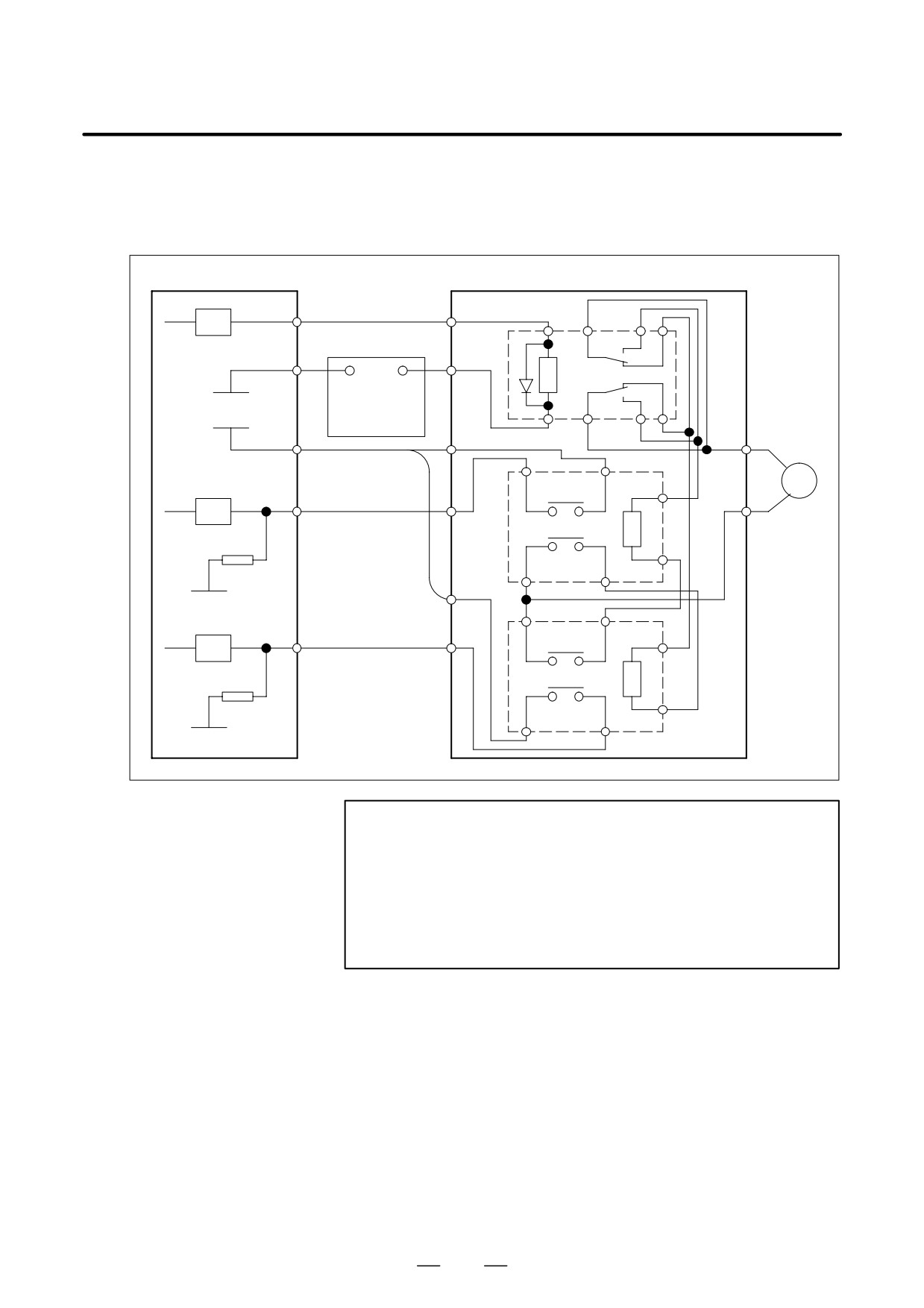
Details of Connection between PMC and Switching Unit
It shows the case that the status of the electromagnetic contactors both for
the high-speed range and for the low-speed range is input.
PMC
Switching unit
Power-line change signal
DV
Relay
0V
+24V
+24V stabirized
0V
power supply
+24V
200VAC
Auxiliary
A contact
RV
Low-speed side MCC
status signal
MCC1
Auxiliary
B contact
0V
Auxiliary
B contact
RV
High-speed side MCC
status signal
MCC2
Auxiliary
A contact
0V
NOTE
1
The main contact terminals and power line in contact are
omitted.
2
Add a surge absorber to the electromagnetic contactor
operation coil as necessary.
3
Use a power-line switching electromagnetic contactor with
the proper capacity for each spindle motor.
519
11. OPTION RELATED TO SPINDLE
B-65162E/03
11.5.5
Spindle Control
Signals
(1)
Input Signals (DI Signals) PMC to CNC
(a)
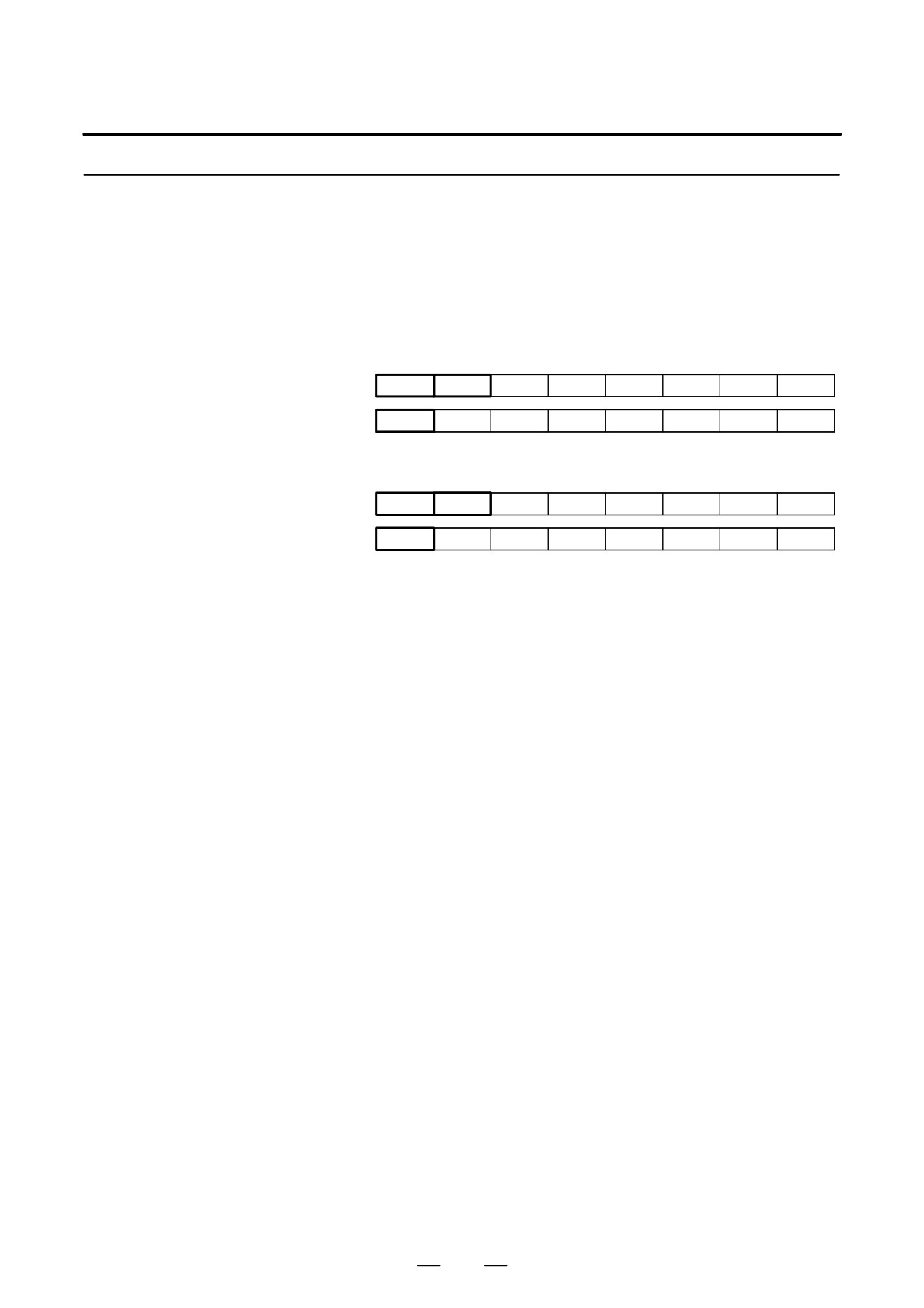
Signal addresses
First spindle control input signal
FS0
FS15
FS16
#7
#6
#5
#4
#3
#2
#1
#0
RCHA
RSLA
INTGA
SOCNA
MCFNA
SPSLA
*ESPA
ARSTA
G230
G226
G071
G231
G229
G072
RCHHGA
MFNHGA
INCMDA
OVRA
DEFMDA
NRROA
ROTAA
INDXA
Second spindle control input signals
FS0
FS15
FS16
#7
#6
#5
#4
#3
#2
#1
#0
RCHB
RSLB
INTGB
SOCNB
MCFNB
SPSLB
*ESPB
ARSTB
G234
G234
G075
G235
G237
G076
RCHHGB
MFNHGB
INCMDB
OVRB
DEFMDB
NRROB
ROTAB
INDXB
(b)
Switching request signal (RSLA)
[Function]
It is used as an instruction signal which selects power characteristics.
0 : The high-speed range is selected.
1 : The low-speed range is selected.
[Usage]
This instruction is usually set according to the velocity command (S
instruction). In this case, parameter No. 4019 #4=1 (FS16) is set to work
the switching operation after speed detecting signal (SDTA) is confirmed
on the spindle side, because a low-speed range is selected immediately
after the velocity command changes from a high speed to a low speed
above the switching point.
In addition, there is a method that this instruction is selected by the speed
detecting signal (SDTA) which is one of output signals of CNC (DO
signal). But, please note that this method changes the speed detecting
signal in the following cases.
D When the motor speed crosses the speed detection level in the constant
surface speed control.
At using a low-speed range, the switching-operation can be prevented
by clamping at the switching speed with the instruction (G50, G92)
that clamps the maximum spindle speed at the constant surface speed
control.
D In the case that the motor speed crosses the speed detection level when
the speed is changed by a spindle override.
Since the power of motor is turned off in switching-operation when the
speed range switching control works in the following control modes,
please select either speed range beforehand, and please do not change the
switching request signal while working.
D Rigid tapping mode
D Cs contouring control mode
D Spindle synchronization control mode
520
B-65162E/03
11. OPTION RELATED TO SPINDLE
D Spindle indexing mode
D The spindle orientation is completed.
(c)
Electromagnetic contactor for the speed range switching status signal (RCHA)
[Function] The opening and closing status signal of the electromagnetic contactor for
a low-speed range of the spindle motor is input.
0 : The low-speed range side electromagnetic contactor is open.
1 : The low-speed range side electromagnetic contactor is closed.
[Usage] The status of the auxiliary contact (”A” contact) of electromagnetic
contactor for a low-speed is usually input.
The status of the low-speed range side electromagnetic contactor is input
as this signal for parameter NO. 4014 #3=1 (FS16).
[Function] The selection status signal of the electromagnetic contactor for the spped
range switching of the spindle motor is inputted.
0 : The high-speed range is selected.
1 : The low-speed range is selected.
[Usage] When the electromagnetic contactor changes from the low-speed side to
the high-speed side, this signal is set from ”1” to ”0” after it is confirmed
that the electromagnetic contactor on the low-speed side is off and that the
electromagnetic contactor on the high-speed side is on.
When the electromagnetic contactor changes from the high-speed side to
the low-speed side, this signal is set from ”0” to”1” after it is confirmed
that the electromagnetic contactor on the high-speed side is off and that
the electromagnetic contactor on the low-speed side is on.
(d)
High-speed range side electromagnetic contactor status signal (RCHHGA)
[Function] The opening and closing status signal of the electromagnetic contactor for
a high-speed range of the spindle motor is input.
0 : The high-speed range side electromagnetic contactor is open.
1 : The high-speed range side electromagnetic contactor is closed.
[Usage] The status of the auxiliary contact (”A” contact) of the electromagnetic
contactor for a high-speed range is usually input.
This signal is effective for parameter NO. 4014 #3=1 (FS16).
521
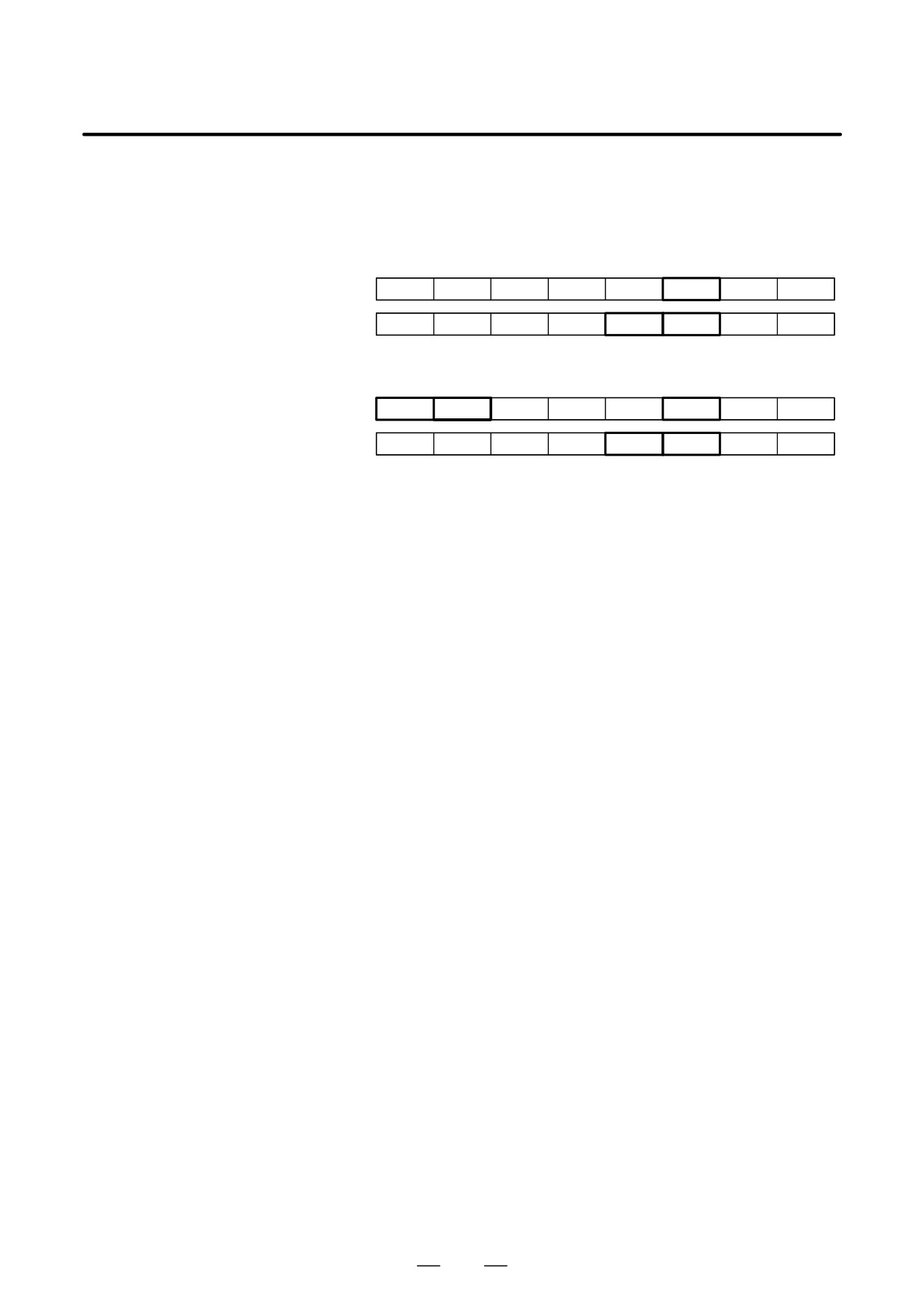
11. OPTION RELATED TO SPINDLE
B-65162E/03
(2)
Output Signal (DO signal) CNC to PMC
(a)
Signal addresses
First spindle control output signal
FS0
FS15
FS16
#7
#6
#5
#4
#3
#2
#1
#0
ORARA
TLMA
LDT2A
LDT1A
SARA
SDTA
SSTA
ALMA
F281
F229
F045
MOAR2A
MOAR1A
POAR2A
SLVSA
RCFNA
RCHPA
CFINA
CHPA
F282
F228
F046
Second spindle control output signals
FS0
FS15
FS16
#7
#6
#5
#4
#3
#2
#1
#0
ORARB
TLMB
LDT2B
LDT1B
SARB
SDTB
SSTB
ALMB
F285
F245
F049
MOAR2B
MOAR1B
POAR2B
SLVSB
RCFNB
RCHPB
CFINB
CHPB
F286
F244
F050
(b)
Power-line switching signal (RCHPA)
[Function] It is an instruction signal to select the electromagnetic contactor for the
speed range switching of the spindle motor.
0 : The electromagnetic contactor for a high-speed range should be
selected.
1 : The electromagnetic contactor for a low-speed range should be
selected.
[Usage] When switching request signal (RSLA) changes, the power supply to the
motor is automatically turned off.
Power supply OFF status continues until the switching completion signal
(RCFNA) changes.
At changing from the low-speed side to the high-speed side, this signal
changes from ”1” to ”0” after the switching request signal (RSLA) is
received. As a result, the electromagnetic contactor for a low-speed range
is first turned off. After it is confirmed to have turned off the
electromagnetic contactor for a low-speed range, the electromagnetic
contactor for a high-speed range is turned on.
At changing from the high-speed side to the low-speed side, this signal
changes from ”0” to ”1” after the switching request signal (RSLA) is
received. As a result, the electromagnetic contactor for a high-speed
range is first turned off. After it is confirmed to have turned off the
electromagnetic contactor for a high-speed range, the electromagnetic
contactor for a low-speed range is turned on.
(c)
Switching completion signal (RCFNA)
[Function] This signal shows by which speed range the spindle motor is controlled.
0 : It is controlled by a high-speed range.
1 : It is controlled by a low-speed range.
[Usage] Switching request signal (RSLA) changes. And after it is confirmed that
this signal is corresponding to the switching request signal (RSLA), it
moves to the next movement.
Since the motor power is turned off until this signal is corresponding to
the switching request signal (RSLA) after the change of the switching
request signal (RSLA), please note not to apply the cutting load, etc. to
the spindle in the switching-operation.
522
B-65162E/03
11. OPTION RELATED TO SPINDLE
(d)
Speed detecting signal (SDTA)
[Function]
It becomes ”1” while the motor speed is below the level (the switching
point is normally set.) that is set by parameter (No.4023 (FS16)).
0 : Motor speed is above the switching point.
1 : Motor speed is below the switching point.
[Usage]
It can be used for the switching point detection.
However, in the case that switching-operation is done according to this
signal, please note that this signal is changed by speed’s changing when
driven near the switching point and switching-operation is occasionally
done.
In this case, please do the switching control with the velocity command
(S instruction).
Hysteresis is given to this signal.
Quantity of hysteresis is set to 20 min-1 as an initial parameter. And it
can be changed by the parameter (NO. 4160 (FS16)).
This width of hysteresis is set to the value with margin, which is two times
value of measured speed change at switching-operation.
It is calculated by the following equation as a standard of the set data.
(Width of hysteresis) =
(Switching-operation time)
(Max. speed)min-1
0.2 :min-1
(Acceleration time up to the max. speed)
When motor load at switching-operation is supposed
to be 20 percent of maximum output torque
523
11. OPTION RELATED TO SPINDLE
B-65162E/03
11.5.6
Sequence
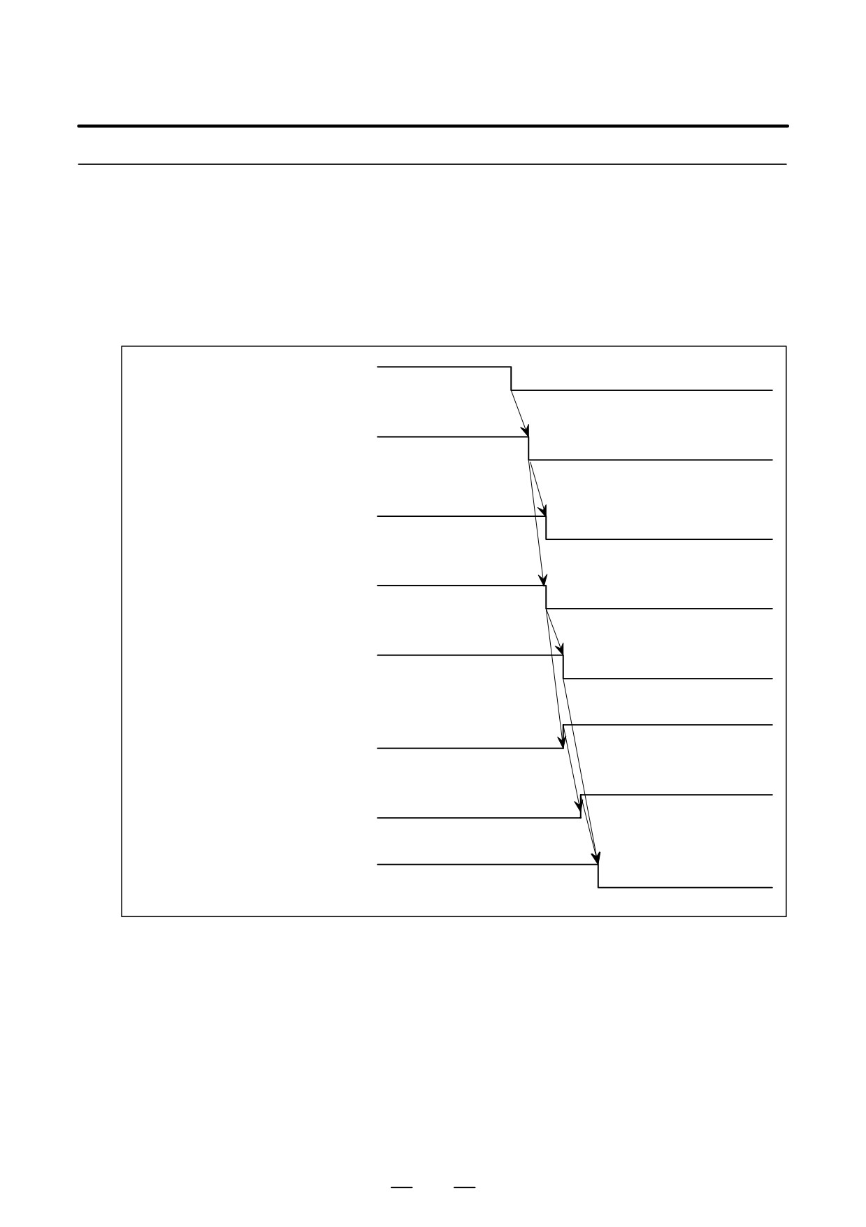
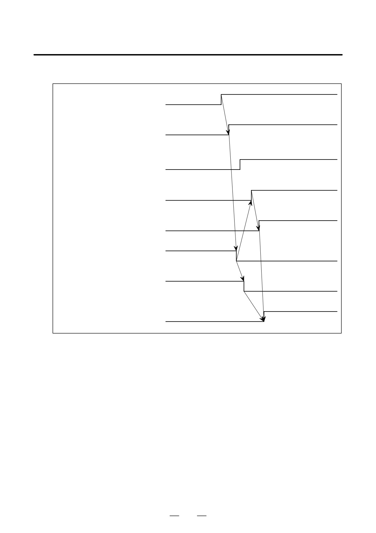
(1) When the Status of both Electromagnetic Contactors for a Low-speed Range (RCHA) and for a High-speed
Range (RCHHGA) is Confirmed and the Speed Range Switching Control Works
Parameter No. 4014 #3=1 (FS16)
(a) Switching-operation of a low-speed range ³ a high-speed range
Switching request signal (RSLA)
High-speed (=0)
Low-speed (=1)
PMC ³ CNC
Power-line switching signal (RCHPA)
CNC ³ PMC
High-speed (=0)
Low-speed (=1)
Clutch/gear signal
High-speed (=0)
(CTH1A, 2A) PMC ³ CNC
Low-speed (=1)
Low-speed side electromagnetic contactor
Open
Closed
Low-speed side electromagnetic contactor
status signal (RCHA)
Open (=0)
Closed (=1)
PMC ³ CNC
High-speed side electromagnetic contactor
Open
Closed
High-speed side electromagnetic contactor
Open (=0)
status signal (RCHHGA)
Closed (=1)
PMC ³ CNC
Switching completion signal (RCFNA)
High-speed (=0)
CNC ³ PMC
Low-speed (=1)
524
B-65162E/03
11. OPTION RELATED TO SPINDLE
(b) Switching-operation of a high-speed range → a low-speed range
Switching request signal (RSLA)
High-speed (=0)
Low-speed (=1)
PMC ³ CNC
High-speed (=0)
Power-line switching signal (RCHPA)
Low-speed (=1)
CNC ³ PMC
High-speed (=0)
Clutch/gear signal
Low-speed (=1)
(CTH1A, 2A) PMC ³ CNC
Open
Closed
Low-speed side electromagnetic contactor
Low-speed side electromagnetic contactor
Open (=0)
Closed (=1)
status signal (RCHA)
PMC ³ CNC
Closed
Open
High-speed side electromagnetic contactor
High-speed side electromagnetic contactor
status signal (RCHHGA)
Closed (=1)
Open (=0)
PMC ³ CNC
High-speed (=0)
Low-speed (=1)
Switching completion signal (RCFNA)
CNC ³ PMC
525
11. OPTION RELATED TO SPINDLE
B-65162E/03
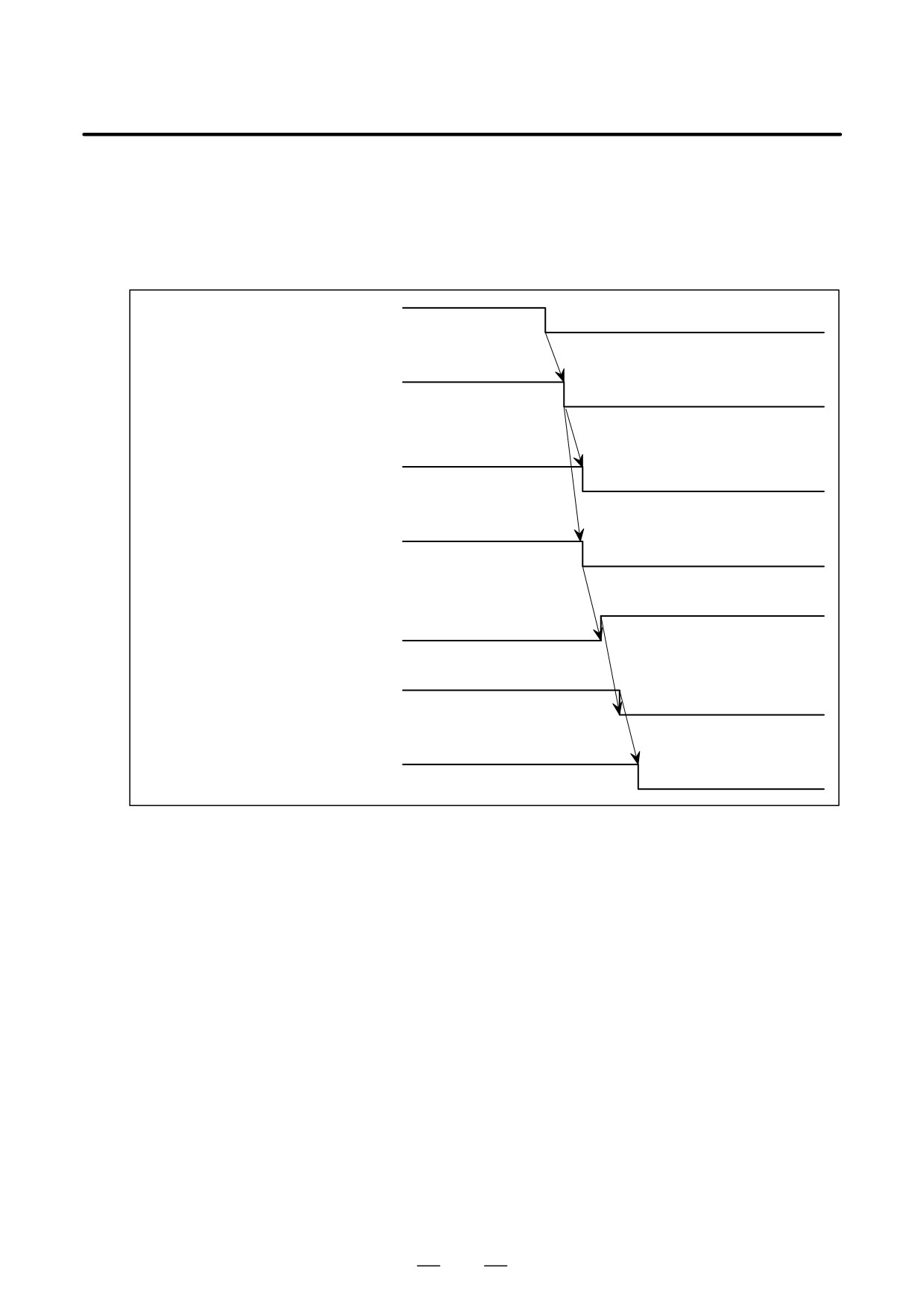
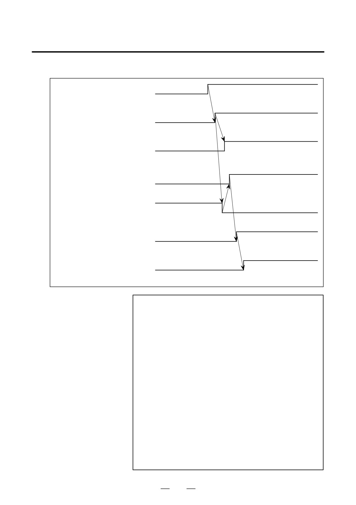
(2) When the Speed Range Switching Control Works by Confirming Only the Power-line Status Check Signal
(RCHA)
For parameter No. 4014 #3=0 (FS16)
(a) Switching-operation of a low-speed range → a high-speed range
Switching request signal (RSLA)
High-speed (=0)
Low-speed (=1)
PMC ³ CNC
Power-line switching signal (RCHPA)
Low-speed (=1)
High-speed (=0)
CNC ³ PMC
High-speed (=0)
Clutch/gear signal
Low-speed (=1)
(CTH1A, 2A) PMC ³ CNC
Closed
Open
Low-speed side electromagnetic contactor
Open
Closed
High-speed side electromagnetic contactor
Power line status check signal (RCHA)
Low-speed (=1)
High-speed (=0)
PMC ³ CNC
Switching completion signal (RCFNA)
High-speed (=0)
Low-speed (=1)
CNC ³ PMC
526
B-65162E/03
11. OPTION RELATED TO SPINDLE
(b) Switching operation of a high speed range → a low-speed range
Switching request signal (RSLA)
High-speed (=0)
Low-speed (=1)
PMC ³ CNC
Power-line switching signal (RCHPA)
High-speed (=0)
Low-speed (=1)
CNC ³ PMC
High-speed (=0)
Low-speed (=1)
Clutch/gear signal
(CTH1A, 2A) PMC ³ CNC
Open
Closed
Low-speed side electromagnetic con-
tactor
Closed
Open
High-speed side electromagnetic con-
tactor
High-speed (=0)
Low-speed (=1)
Power-line status check signal (RCHA)
PMC ³ CNC
High-speed (=0)
Low-speed (=1)
Switching completion signal (RCFNA)
CNC ³ PMC
NOTE
1
A parameter is provided to disable switching from
high-speed range to low-speed range at speeds
exceeding the switchable speed (speed detection signal
SDTA = 0).
2
Switch the clutch/gear signals (CTH1A, CTH2A) so that
data such as velocity loop gain can be set separately for
low-speed characteristics mode and high-speed
characteristics mode.
3
An alarm (AL-15) is issued if the magnetic contactor signal
is not applied within one second of the power line switch
signal being output. Ensure that the magnetic contactor
signal is applied within one second of the power line switch
signal being output.
4
Because there are electromagnetic contactor operation delays
etc. when checking electromagnetic contactor MCC1, MCC2
selection conditions in electromagnetic contactor MCC1 only,
auxiliary contacts make sure that there is a minimum time lag of
50msec between operating the MCC1, MCC2 switch and
changing the power cable condition verification signal (RCHA) with
the power cable switching cable (RCHPA).
527
11. OPTION RELATED TO SPINDLE
B-65162E/03
11.5.7
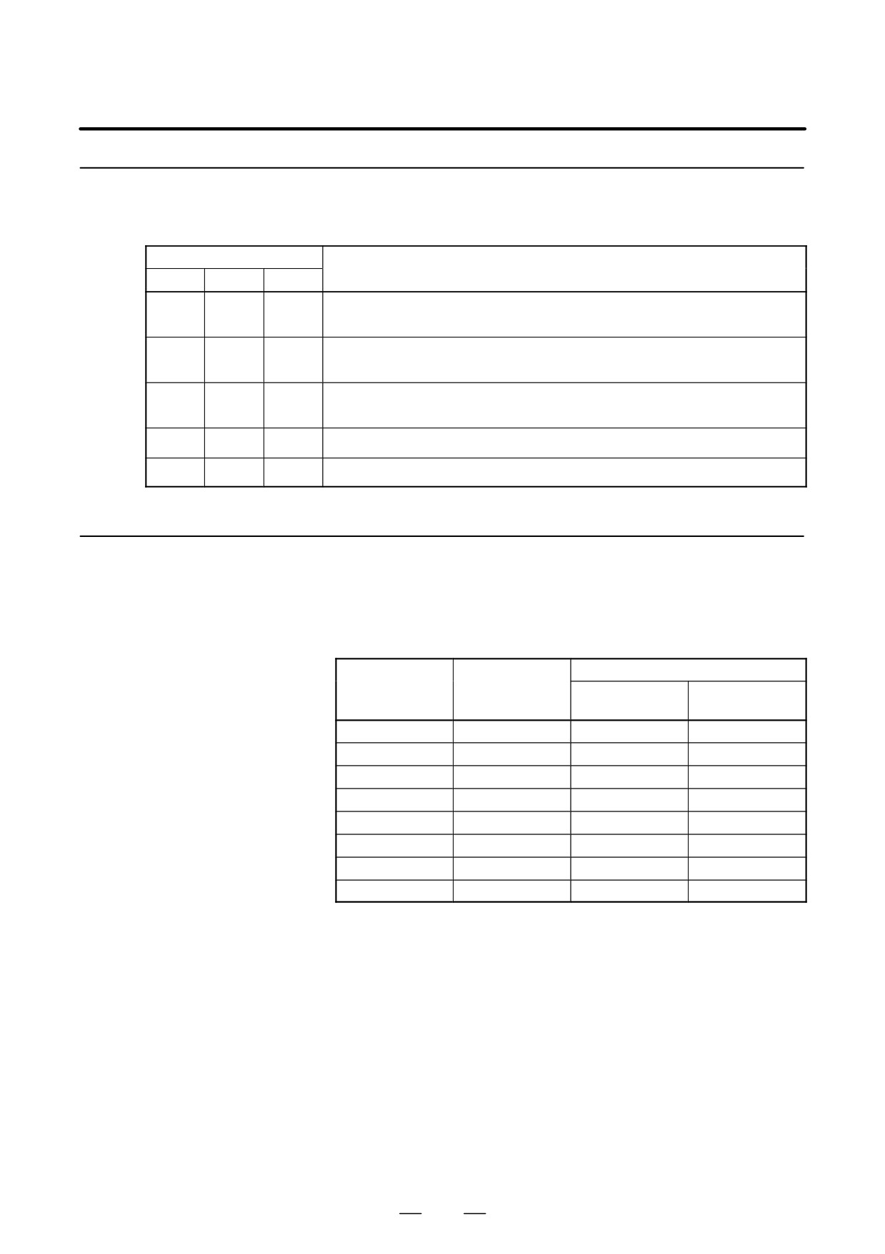
The table below lists the parameters related to the speed range switching
control function. Refer to the Parameter manual for details.
Parameters
Parameter No.
Description
FS0
FS15
FS16
Whether the speed range switching control function is used (Set to 1.)
6515#2
3015#2
4015#2
(CNC software option is necessary.)
Function for checking the statuses of the magnetic contactors for both high-speed
6514#3
3014#3
4014#3
range and low-speed range
Function for checking the speed detection signal when switching from high-speed
6519#4
3019#4
4019#4
range to low-speed range
6523
3023
4023
Speed detection level
6924
3304
4160
Hysteresis for the speed detection level
11.5.8
Cautions in Use
D Use an electromagnetic contactor for speed range switching whose
capacity is suited for the spindle amplifier module
For the sake of reference, the table below lists the model ratings of
electromagnetic contactors made by Fuji electric and Telemechanic.
Electromagnetic contactor
Applicable
30-minute rated
spindle amplifier
current of the
Flowing current
Model ratings
module
amplifier (A)
(A)
SPM-2.2
13.4
SC-4-0
22
SPM-5.5
30
SC-1N
50
SPM-11
48
SC-2N
60
SPM-15
63
SC-2SN
80
SPM-22
95
SC-4N
135
SPM-26
111
SC-5N
150
SPM-30
133
SC-6N
150
SPM-45
198
SC-8N
260
D In order to suppress electrical noise generated at switching in the
electromagnetic contactor for speed range switching, use a surge
absorber containing resistor and capacitor.
D Setting the machine ready signal (MRDYA)
For the purpose of safety, use two signals in the sequence that makes
the system operable. These are the emergency stop signal (*ESPA) and
machine ready signal (MRDYA). Set the machine ready signal
(MRDYA) to 1 to allow operation of the machine.
D When conducting rigid tapping, set the desired speed range in advance
and do not perform switching.
Accordingly, when conducting rigid tapping, although the speed
detection signal (SDTA) will be output from the spindle amplifier, be
sure that this signal is ignored.
528
B-65162E/03
11. OPTION RELATED TO SPINDLE
D Speed detection signal (SDTA) and selection signal
Two windings are installed within the AC spindle motor. Output
power characteristics can be changed by switching these two
windings.
When conducting this speed range switching (during rotation) and the
rigid tapping, the control may be limited by only the high-speed
winding.
Ensure a sequence in the PMC that allows selection of 2 output power
characteristics and enables selection of a switching sequence during
rotation.
D Use gear/clutch signal CTH1A and CTH2A to be able to set different
velocity loop gains for low-speed and high-speed.
529
11. OPTION RELATED TO SPINDLE
B-65162E/03
11.6
SPINDLE SWITCHING
CONTROL
11.6.1
Spindle switching control uses a spindle amplifier module TYPE III in a
machine that has two spindle motors but does not move both
General
simultaneously. Furthermore, it has an electromagnetic contactor to
change power lines on the outside of the spindle amplifier. The function
works by switching between motors with the same characteristics or two
motors that have different output power characteristics.
It has the following uses.
D In turning centers etc. it uses a single spindle amplifier to switch the
power line, velocity feedback signal line and the orientation signal line
using the Main Spindle Motor for turning and the Sub Spindle Motor
for rotation tools.
D It uses a single spindle unit to switch the power line, velocity feedback
signal line and the orientation signal line using the vertical axis motor
and horizontal axis motor of the machine tool with five- surface
machining capability.
NOTE
This function is not available for αC series.
11.6.2
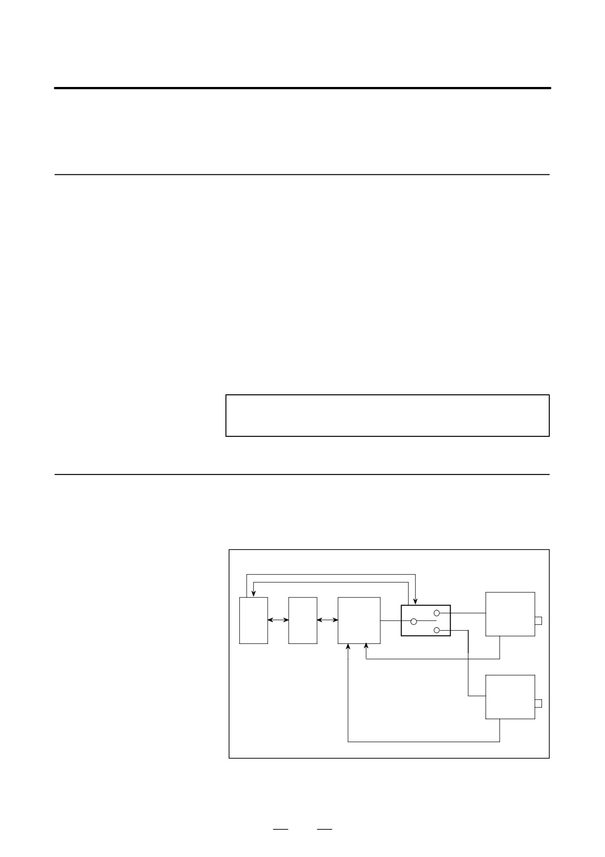
To control two spindle motors with one spindle amplifier, the following
are additionally required:
Configuration
D Magnetic contactor (switch unit) for power line switching
D Signals between the PMC and switch unit
Switch signal
Status check signal
Switch unit
Spindle
Main
amplifier
spindle
Power
PMC
CNC
module
motor
line
(SPM)
Type 3
Feedback signal
Sub
spindle
motor
Feedback signal
530
B-65162E/03
11. OPTION RELATED TO SPINDLE
11.6.3
Specifications
D
By using a spindle amplifier module (SPM) of Type 3, two spindle
motors are driven. The two spindle motors are switched; the two
spindle motors cannot be driven at the same time.
D
A combination of a main spindle motor and sub spindle motor can be
selected freely from those spindle motors that can be driven by the
spindle amplifier module. From the spindle amplifier modules that
match two spindle motors, select that spindle amplifier module that
has the larger capacity. Depending on the combination of spindle
motors and spindle amplifier module, the parameters may have to be
modified.
D
The smallest Type 3 spindle amplifier module is SPM-11. Use
SPM-11 even when small spindle motors are used.
D
The feedback signals of the following detectors are switched:
Detector built into a motor: M sensor, MZ sensor, BZ sensor (for a
built-in motor)
Detector attached to the spindle: Position coder, magnetic sensor (for
orientation), proximity switch (external one-rotation signal)
D
Output switch control can be applied to the main spindle motor and sub
spindle motor.
D
Rigid tapping can be performed with the main spindle motor and sub
spindle motor.
D
Orientation of position coder type can be performed with the main
spindle motor and sub spindle motor when a stop position is specified
by a parameter.
D
Orientation of magnetic sensor type can be performed with the main
spindle motor and sub spindle motor.
D
To check the power line state more precisely, the state of the magnetic
contactor of the main spindle motor and sub spindle motor can be
entered. The following parameter settings are used for this purpose:
FS16: Bit 2 of parameter No. 4014 = 1
FS15: Bit 2 of parameter No. 3014 = 1
FS0: Bit 2 of parameter No. 6514 = 1
D
As the error detection function for switching operation, the alarm
(AL-5) is issued if the magnetic contactor state signal (MCFNA,
MFNHGA) is not applied within one second of the power line switch
signal (CHPA) being output.
11.6.4
Restrictions
D With the spindle switch control function, the method of mounting a BZ
sensor instead of a position coder onto the spindle cannot be used.
D The stop position external setting type position coder method spindle
orientation can be used only on MAIN side. It is not available on SUB
side.
D Spindle synchronization control is only available on the MAIN side.
It is not available on the SUB side.
D The spindle index function (Cs axis control) is only available on the
MAIN side. It is not available on the SUB side.
531
11. OPTION RELATED TO SPINDLE
B-65162E/03
D Cs contouring control cannot be used both MAIN and SUB side.
D Gear change on the SUB side can be set to 2 stages.
D The spindle switching function can be used for the Power Mate D/F.
D The spindle switching function cannot be used for αC series.
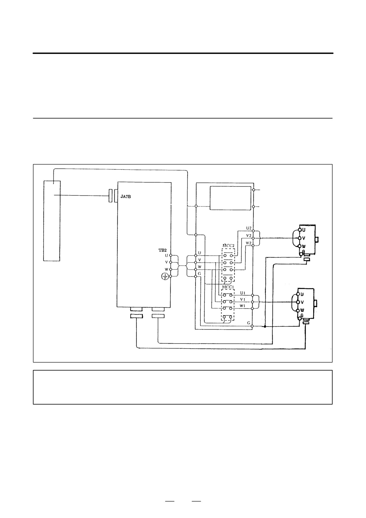
11.6.5
Connection
(1) Connection
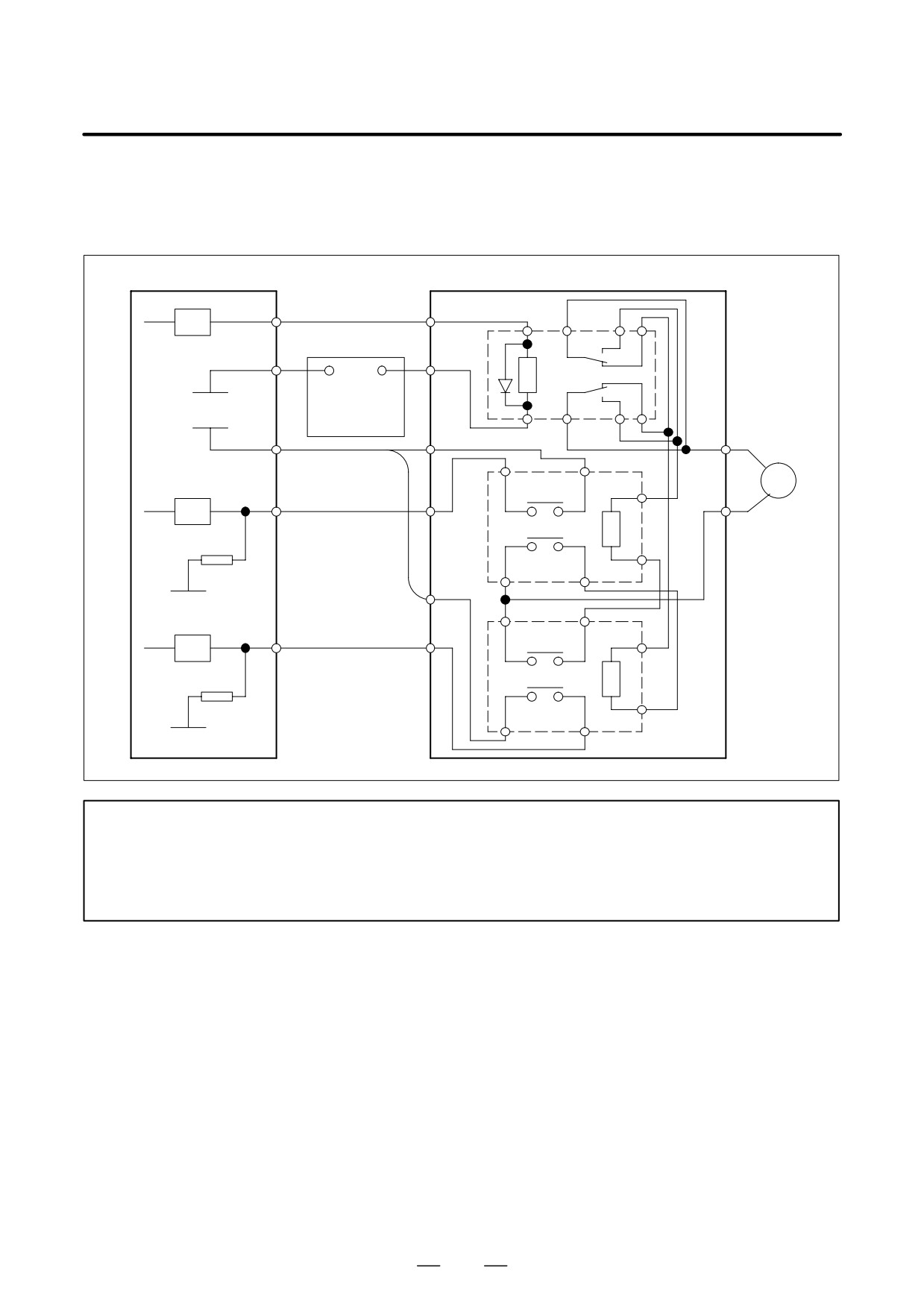
Relay circuit
Communication
cable
Magnetic
Single-phase
contactor
200 VAC
switch circuit
CNC
Spindle amplifier
Magnetic contactor
and
module (SPM)
for power line
Main spindle motor
PMC
Type 3
switching
Auxiliary
contact
Sub spindle motor
JY2
JY6
Auxiliary
contact
NOTE
In this figure, the power supply module is omitted. The machine tool builder is to provide all units
and cables other than the spindle amplifier and AC spindle motors.
532
B-65162E/03
11. OPTION RELATED TO SPINDLE
(2)
Details of Connections for the PMC and Switching Unit
It shows the case that the status of the electromagnetic contactors both on
the MAIN spindle side and on the SUB spindle side is input.
PMC
Switching unit
Power-line switching
signal
DV
Relay
0V
+24V
+24V stabirized
0V
power supply
+24V
200VAC
Auxiliary
A contact
RV
Sub spindle side MCC
status signal
MCC1
Auxiliary
B contact
0V
Auxiliary
B contact
RV
Main spindle side MCC
status signal
MCC2
Auxiliary
A contact
0V
NOTE
1
The main contact terminals and power line in contact are omitted.
2
Add a surge absorber to the electromagnetic contactor operation coil as necessary.
3
Use a power-line switching electromagnetic contactor with the proper capacity for each spindle
motor.
533
11. OPTION RELATED TO SPINDLE
B-65162E/03
11.6.6
Spindle Control
Signals
(1)
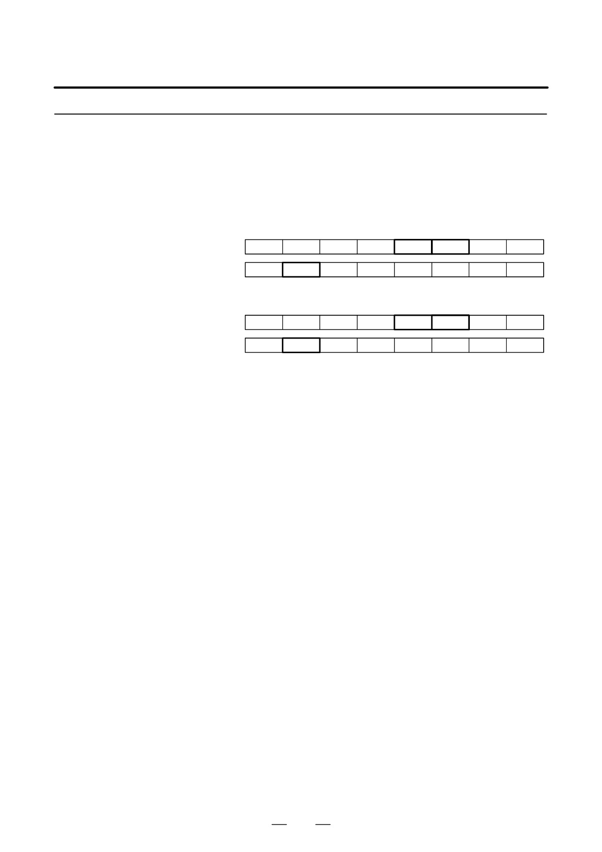
Input Signals (DI Signals) PMC to CNC
(a)
Signal addresses
First spindle control input signal
FS0
FS15
FS16
#7
#6
#5
#4
#3
#2
#1
#0
RCHA
RSLA
INTGA
SOCNA
MCFNA
SPSLA
*ESPA
ARSTA
G230
G226
G071
G231
G229
G072
RCHHGA
MFNHGA
INCMDA
OVRA
DEFMDA
NRROA
ROTAA
INDXA
Second spindle control input signals
FS0
FS15
FS16
#7
#6
#5
#4
#3
#2
#1
#0
G234
G234
G075
RCHB
RSLB
INTGB
SOCNB
MCFNB
SPSLB
*ESPB
ARSTB
G235
G237
G076
RCHHGB
MFNHGB
INCMDB
OVRB
DEFMDB
NRROB
ROTAB
INDXB
(b)
Switching request signal (SPSLA)
[Function] It is used as an instruction signal which selects the spindle motor.
0 : The main spindle motor is selected.
1 : The sub spindle motor is selected.
[Usage] This signal is changed after stopping the spindle motor.
Speed zero signal (SSTA) is used for confirming that a spindle motor is
stopping.
Since it is necessary that motor power is off for spindle changing, please
set off the spindle rotation command (SFRA/SRVA) and the spindle
orientatation command (ORCMA) at switching spindle motors.
(c)
Power-line status check signal (MCFNA)
[Function] The selection status signal of the electromagnetic contactor for switching
the spindle motor power-lines is input.
0 : The main spindle is selected.
1 : The sub spindle is selected.
[Usage] Usually, the state of the auxiliary contact (contact A) of the magnetic
contactor for the sub spindle motor is entered directly.
[Function] When bit 2 of parameter No. 4014 (FS16) is set to 0, this signal is used
as the power line state check signal. So, the state of selection by the
magnetic contactor for spindle motor power line switching is entered.
0: The main spindle motor is selected.
1: The sub spindle motor is selected.
[Usage] In the case of changing from the main spindle to the sub spindle, this
signal is set from ”1” to ”0” after confirming that the electromagnetic
contactor on the main spindle side is off and that the electromagnetic
contactor on the sub spindle side is on.
In the case of changing from the sub spindle to the main spindle, this
signal is set from ”0” to ”1” after confirming that the electromagnetic
contactor on the sub spindle side is off and that the electromagnetic
contactor on the main spindle side is on.
534
B-65162E/03
11. OPTION RELATED TO SPINDLE
(d)
Main spindle side electromagnetic contactor status signal (MFNHGA)
This signal is effective for parameter NO.4014 #2=1 (FS16)
[Function] The opening and closing status signal of the electromagnetic contactor for
power-line on the main spindle side is input.
0 : The electromagnetic contactor on the main spindle side is open.
1 : The electromagnetic contactor on the main spindle side is closed.
[Usage] The status of the auxiliary contact (”A” contact) of the electromagnetic
contactor on the main spindle side is input.
This signal is valid when bit 2 of parameter No. 4014 (FS16) is set to 1.
(2)
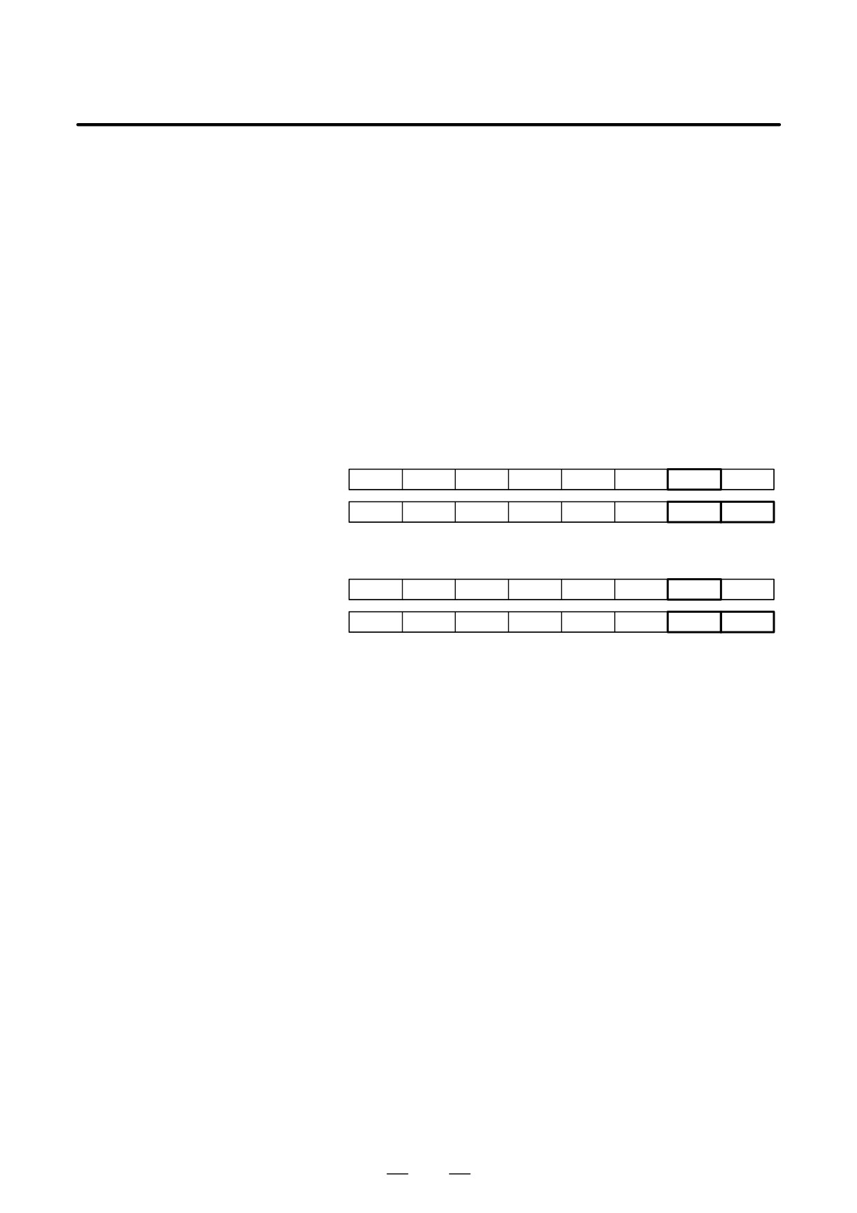
Output Signal (DO signal) CNC to PMC
(a)
Signal addresses
First spindle control output signal
FS0
FS15
FS16
#7
#6
#5
#4
#3
#2
#1
#0
ORARA
TLMA
LDT2A
LDT1A
SARA
SDTA
SSTA
ALMA
F281
F229
F045
MOAR2A
MOAR1A
POAR2A
SLVSA
RCFNA
RCHPA
CFINA
CHPA
F282
F228
F049
Second spindle control output signals
FS0
FS15
FS16
#7
#6
#5
#4
#3
#2
#1
#0
ORARB
TLMB
LDT2B
LDT1B
SARB
SDTB
SSTB
ALMB
F285
F245
F049
MOAR2B
MOAR1B
POAR2B
SLVSB
RCFNB
RCHPB
CFINB
CHPB
F286
F244
F050
(b)
Power-line switching signal (CHPA)
[Function] It is an instruction signal to select the electromagnetic contactor for
switching the spindle motor power-line.
0 : The electromagnetic contactor for the main spindle should be selected.
1 : The electromagnetic contactor for the sub spindle should be selected.
[Usage] This signal is output after receiving the switching request signal
(SPSLA).
This signal selects the electromagnetic contactor for switching the spindle
motor power-line.
At changing from the sub spindle to the main spindle, this signal changes
from ”1” to ”0” after the switching request signal (SPSLA) is received.
As a result, the electromagnetic contactor for the sub spindle is first turned
off. After it is confirmed to have turned off the electromagnetic contactor
for the sub spindle, the electromagnetic contactor for the main spindle is
turned on.
At changing from the main spindle to the sub spindle, this signal changes
from ”0” to ”1” after the switching request signal (SPSLA) is received.
As a result, the electromagnetic contactor for the main spindle is first
turned off. After it is confirmed to have turned off the electromagnetic
contactor for the sub spindle is turned on.
535
11. OPTION RELATED TO SPINDLE
B-65162E/03
(c)
Switching completion signal (CFINA)
[Function] This signal shows by which spindle characteristic the spindle motor is
controlled.
0 : It is controlled by a main spindle characteristic.
1 : It is controlled by a sub spindle characteristic.
[Usage] The switching request signal (SPSLA) changes, and after it is confirmed
that this signal is corresponding to the switching request signal (SPSLA),
it moves to the next movement.
Since it is necessary that the motor power is off until this signal is
corresponding to the switching request signal (SPSLA) after the change
of the switching request signal (SPSLA), please set off the spindle
rotation command (SFRA/SRVA) and the spindle orientation command
(ORCM) at the switching operation.
(d)
Speed zero signal (SSTA)
[Function] It becomes ”1” while the motor speed is below the speed zero detection
level which is set by parameter.
0 : It is above the speed zero detection level.
1 : It is below the speed zero detection level.
[Usage] At switching the spindle, it is necessary both that the motor power is off
and that the motor is stopping.
This signal is used for confirming whether the motor is stopping.
536
B-65162E/03
11. OPTION RELATED TO SPINDLE
11.6.7
Sequence
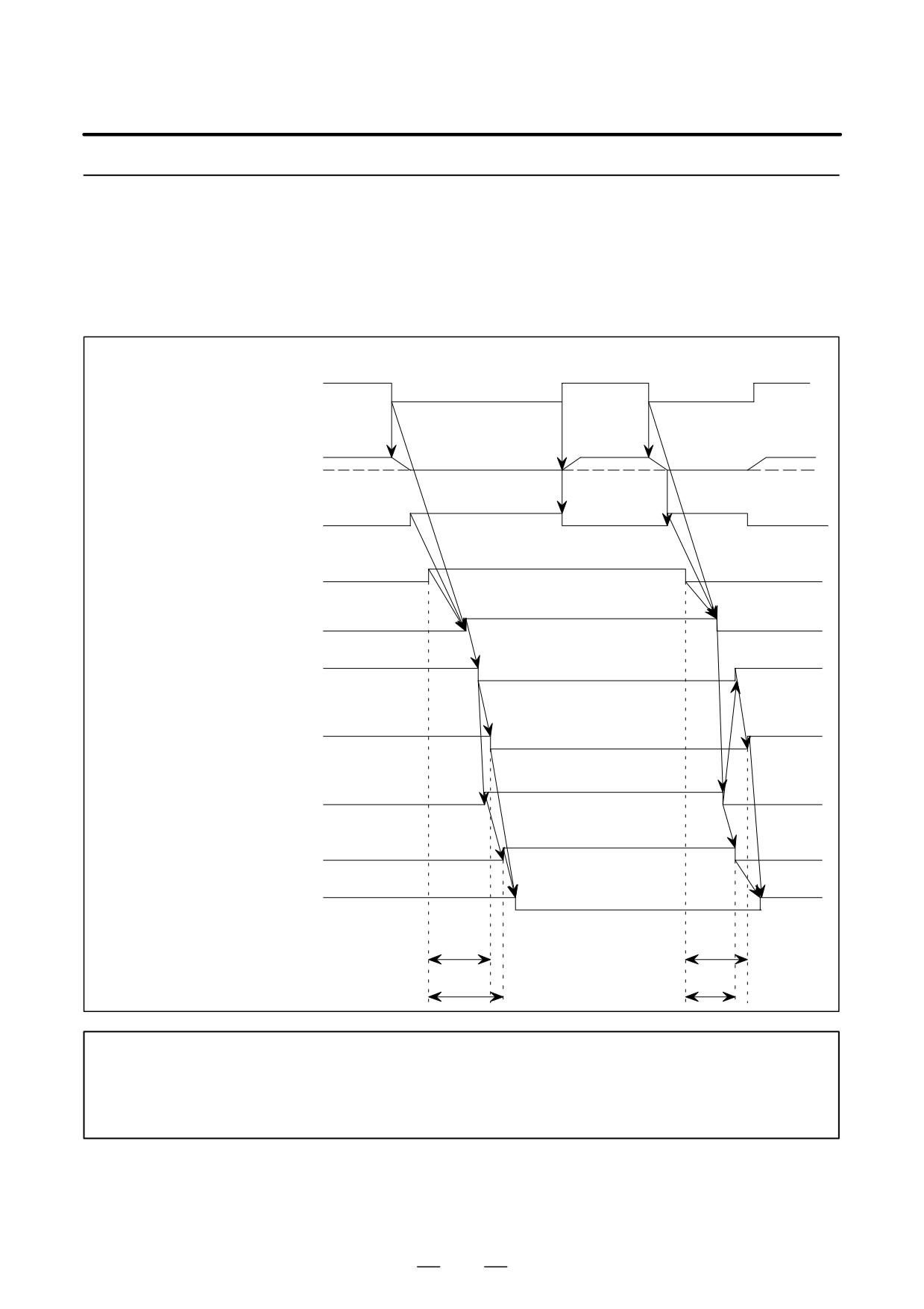
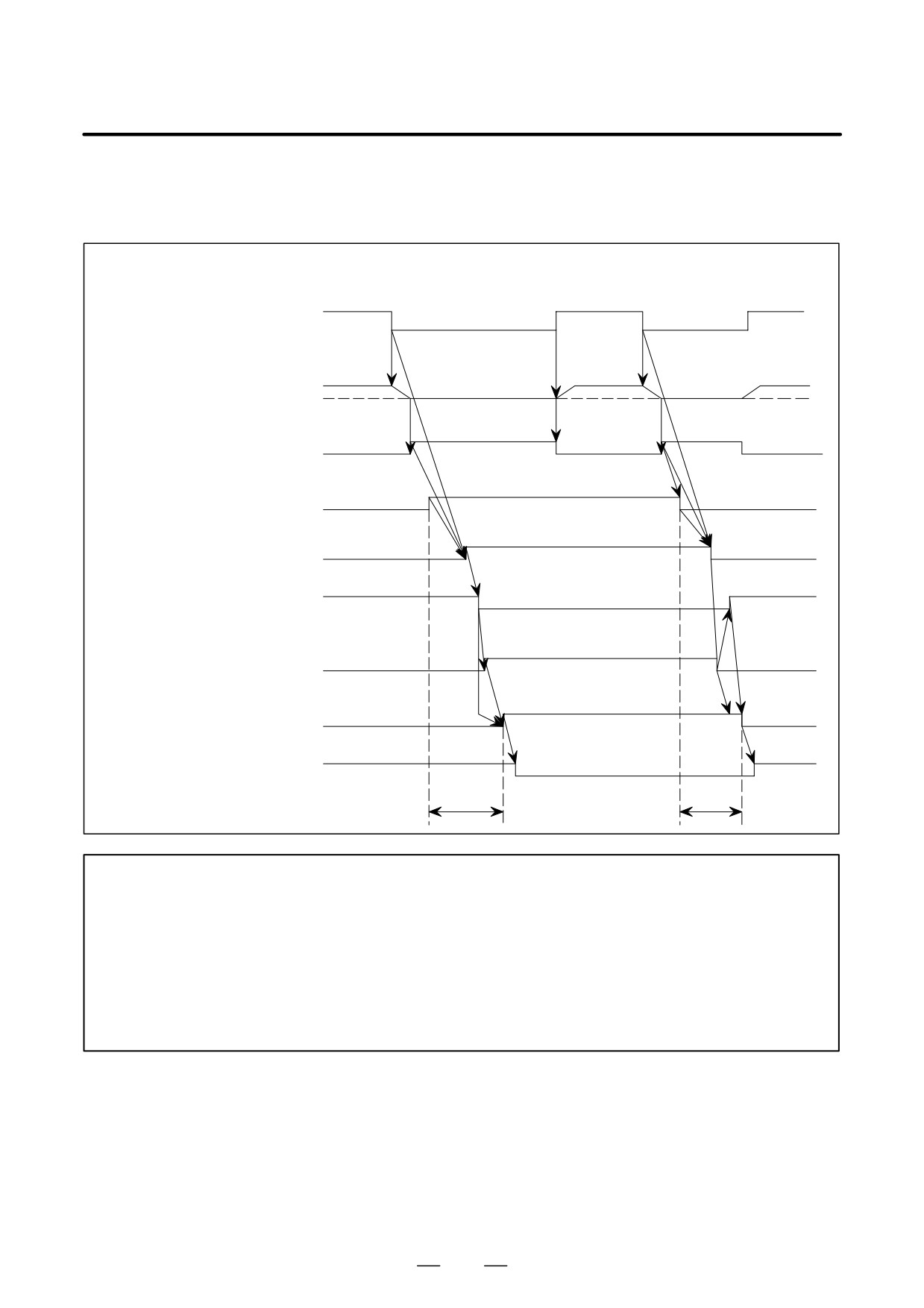
(1) When the Status of both Electromagnetic Contactors for the Sub Spindle (MCFNA) and for the Main Spindle
(MFNHGA) is Confirmed on the Spindle Side and the Spindle Switching Control Works
Parameter NO.4014 #2=1 (FS16)
MAIN SPINDLE ³ SUB SPINDLE ³ MAIN SPINDLE
Spindle forward rotation command
(SFRA) or Spindle reverse rotation
OFF (=0)
OFF (=0)
ON (=1)
ON (=1)
ON (=1)
command (SRVA)
PMC ³ CNC
Spindle motor speed
Stop
Speed zero signal (SSTA)
OFF (=0)
OFF (=0)
OFF (=0)
CNC ³ PMC
ON (=1)
ON (=1)
Switching request signal (SPSLA)
MAIN (=0)
MAIN (=0)
PMC ³ CNC
SUB (=1)
MAIN (=0)
Power-line switching signal (CHPA)
MAIN (=0)
SUB (=1)
CNC ³ PMC
Main side electromagnetic contactor
OPEN
(MCC2)
CLOSED
CLOSED
Main side electromagnetic contactor
CLOSED (=1)
status signal (MFNHGA)
OPEN (=0)
CLOSED (=1)
PMC ³ CNC
Sub side electromagnetic contactor
OPEN
OPEN
CLOSED
(MCC1)
OPEN (=0)
OPEN (=0)
Sub side electromagnetic contactor
CLOSED (=1)
status signal (MCFNA)
PMC ³ CNC
SUB (=1)
Switching completion signal (CFINA)
MAIN
MAIN (=0)
CNC ³ PMC
(=0)
t1
t1’
t1<1sec
t1’<1sec
besides
besides
t2
t2’
t2<1sec
t2’<1sec
NOTE
If the electromagnetic contactor status check signals for the main spindle (MFNHGA) and for
the sub spindle (MCFNA) do not change within 1 second after the switching request signal
(SPSLA) is changed, the alarm occurs.
537
11. OPTION RELATED TO SPINDLE
B-65162E/03
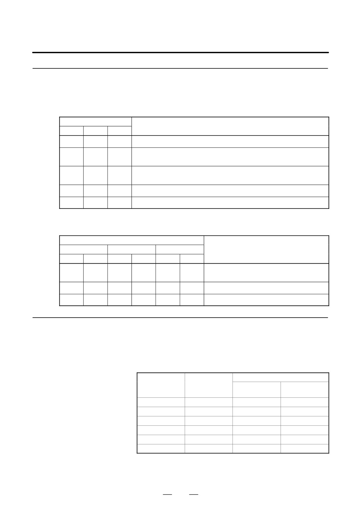
(2) When the Spindle Switching Control Works by Confirming Only the Power-line Status Check Signal (MCFNA)
For parameter No. 4014#2=0 (FS16)
MAIN SPINDLE ³ SUB SPINDLE ³ MAIN SPINDLE
Spindle forward rotation command
(SFRA) or Spindle reverse rotation
OFF (=0)
ON (=1)
OFF (=0)
ON (=1)
ON (=1)
command (SRVA)
PMC ³ CNC
Spindle motor speed
Stop
Speed zero signal (SSTA)
OFF (=0)
OFF (=0)
OFF (=0)
ON (=1)
ON (=1)
CNC ³ PMC
SUB (=1)
MAIN (=0)
Switching request signal (SPSLA)
MAIN (=0)
PMC ³ CNC
MAIN (=0)
MAIN (=0)
Power-line switching signal (CHPA)
SUB (=1)
CNC ³ PMC
OPEN
CLOSED
CLOSED
Main side electromagnetic contactor
(MCC2)
OPEN
OPEN
CLOSED
Sub side electromagnetic contactor
(MCC1)
Power-line status check signal
OPEN (=0)
OPEN (=0)
(MCFNA)
CLOSED (=1)
PMC ³ CNC
Switching completion signal
SUB (=1)
MAIN (=0)
MAIN (=0)
(CFINA)
CNC ³ PMC
t1
t1
G
NOTE
1
Because there are electromagnetic contactor operation delays etc. when checking
electromagnetic contactor MCC1, MCC2 selection conditions in electromagnetic contactor
MCC1 (see PMC and switching unit contact details) only, auxiliary contacts make sure that
there is a minimum time lag of 50 msec between operating the MCC1, MCC2 switch and
changing the power cable condition verification signal (MCFN) with the power cable switching
signal (CHP).
2
If the power-line status signal (MCFNA) doesnot change within 1 second after the switching
request signal (SPSLA) is changed, the alarm occurs.
538
B-65162E/03
11. OPTION RELATED TO SPINDLE
11.6.8
Refer to the Parameter manual for details of parameters.
D Automatic initial setting of spindle parameters can also be performed
Parameters
for the sub spindle.
D The table below lists the parameters related to the spindle switching
control function.
Parameter No.
Description
FS0
FS15
FS16
6514#0
3014#0
4014#0
Whether the spindle switching control function is used (Set to 1.)
Whether the spindle switching control function is enabled during rotation of the sub
6514#1
3014#1
4014#1
spindle
Function for checking the statuses of the magnetic contactors both for the main
6514#2
3014#2
4014#2
spindle and for the sub spindle
6524
3024
4024
Zero speed detection level (for the main spindle)
6163
3343
4199
Zero speed detection level (for the sub spindle)
D The following parameters may have to be changed depending on the
combination of the two motors and the spindle switching control.
Manually change the parameters after automatic parameter setting.
Parameter No.
FS0
FS15
FS16
Description
Main
Sub
Main
Sub
Main
Sub
6513
6153
3013
3333
4013
4189
Data on dead zone for current
#6 to 2
#6 to 2
#6 to 2
#6 to 2
#6 to 2
#6 to 2
6610
6228
3110
3408
4110
4264
Current conversion constant
6612
6230
3112
3410
4112
4266
Current prediction constant
11.6.9
Cautions in Use
D The magnetic contact for switching the power line must have an
adequate capacity for the spindle amplifier module.
The example given below shows the model codes of Fuji Electric Co.,
Ltd.
Magnetic contactor
30min. rated cur-
Applicable
rent for amplifier
Flowing current
spindle amplifier
Model code
(A)
(A)
SPM-11
48
SC-2N
60
SPM-15
63
SC-2SN
80
SPM-22
95
SC-4N
135
SPM-26
111
SC-5N
150
SPM-30
133
SC-6N
150
SPM-45
198
SC-8N
260
D To suppress electrical noise generated while the magnetic contact
switches power lines, use a surge absorber containing resistors and
capacitors.
539
11. OPTION RELATED TO SPINDLE
B-65162E/03
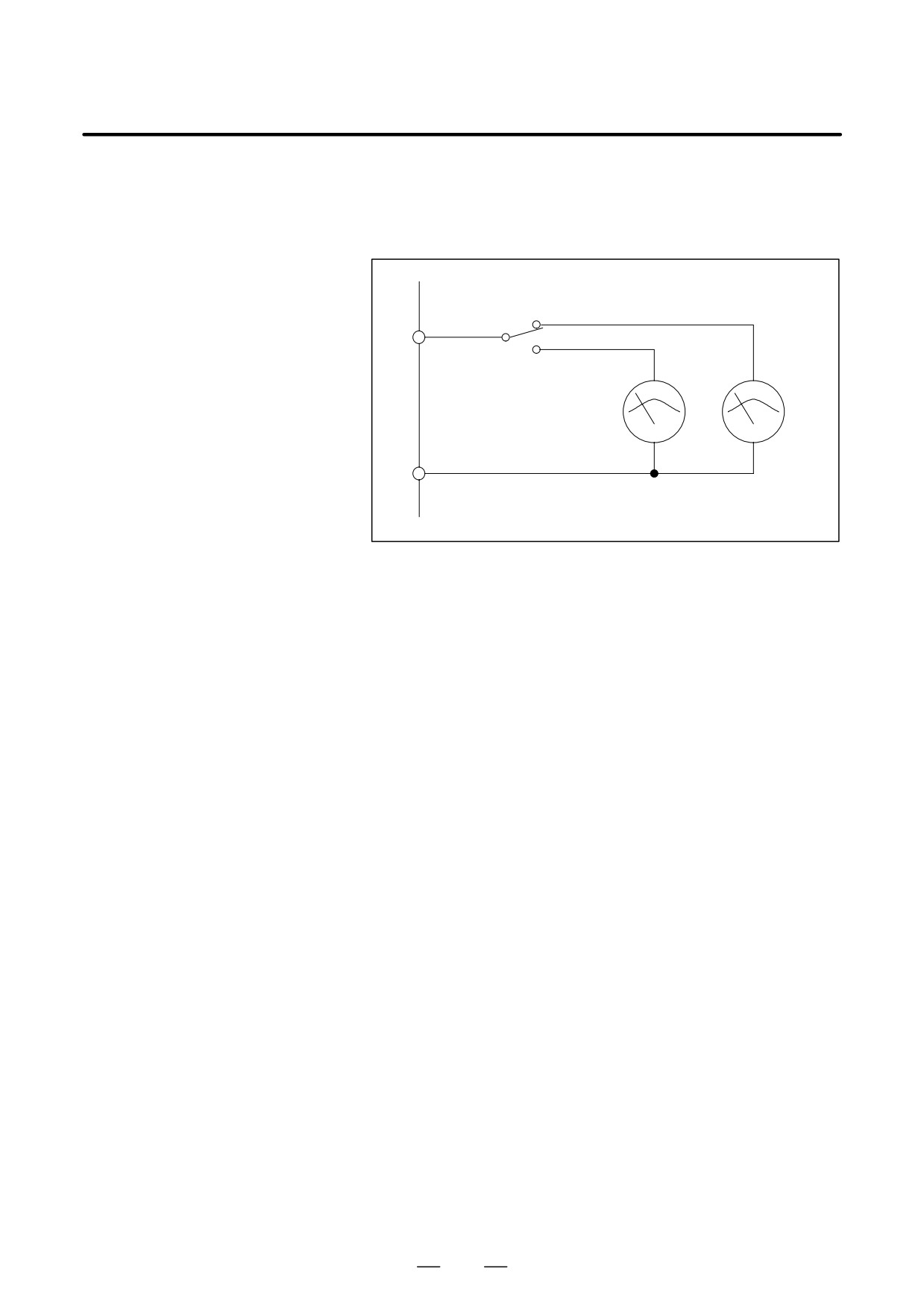
D The indicated voltages for the speed meter and load meter of the main
spindle may differ from those of the sub spindle. In this case, switch
between the speed meter or load meter for the main spindle and sub
spindle as follows.
Switching circuit
SM
or
LM
For sub
For main spindle
spindle
0M
Speed meter or
load meter
540
B-65162E/03
11. OPTION RELATED TO SPINDLE
11.7
SWITCHING UNIT
11.7.1
The switching unit uses an electromagnetic contactor outside the spindle
amplifier module to switch power lines for spindle switching control for
General
two motors or for speed range switching control for a motor in the
following cases:
D Switching a power line from one motor to another motor (spindle
switching control)
D Switching a power line for a motor which has two types of windings
(speed range switching control)
NOTE
This unit cannot be used for αC series.
11.7.2
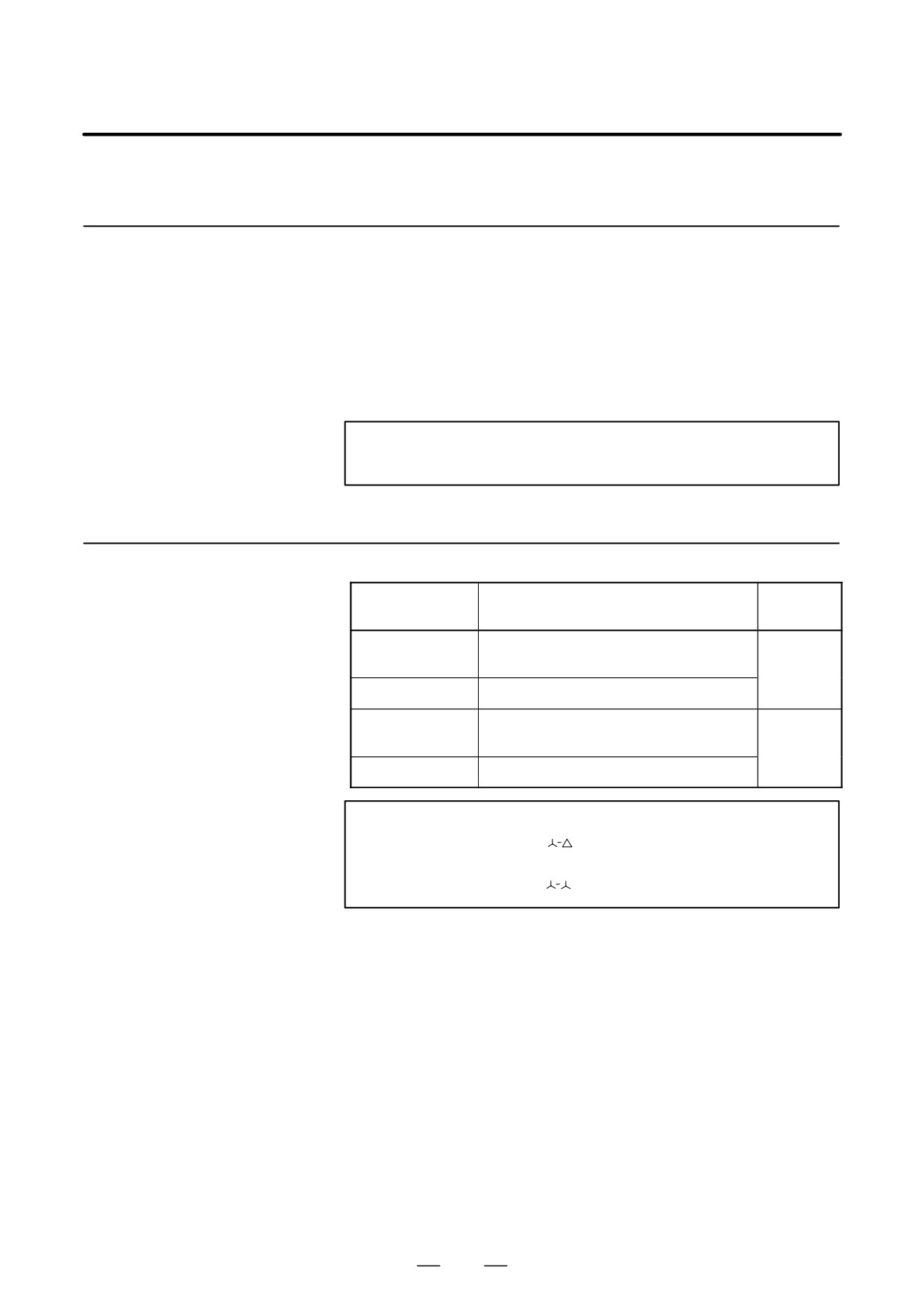
Specification No.
Applicable
Specification No.
Application
amplifier
For spindle switching control and for speed
A06B-6078-K034
range switching control (Type B)
SPM-15 or
less
A06B-6078-K035
For speed range switching control (Type A)
For spindle switching control and for speed
A06B-6078-K036
range switching control (Type B)
SPM-30 or
less
A06B-6078-K037
For speed range switching control (Type A)
NOTE
Type A : Switching the
connection for the motor winding.
Type B : Switching the
connection for the motor winding.
541
11. OPTION RELATED TO SPINDLE
B-65162E/03
11.7.3
Specifications
(1)
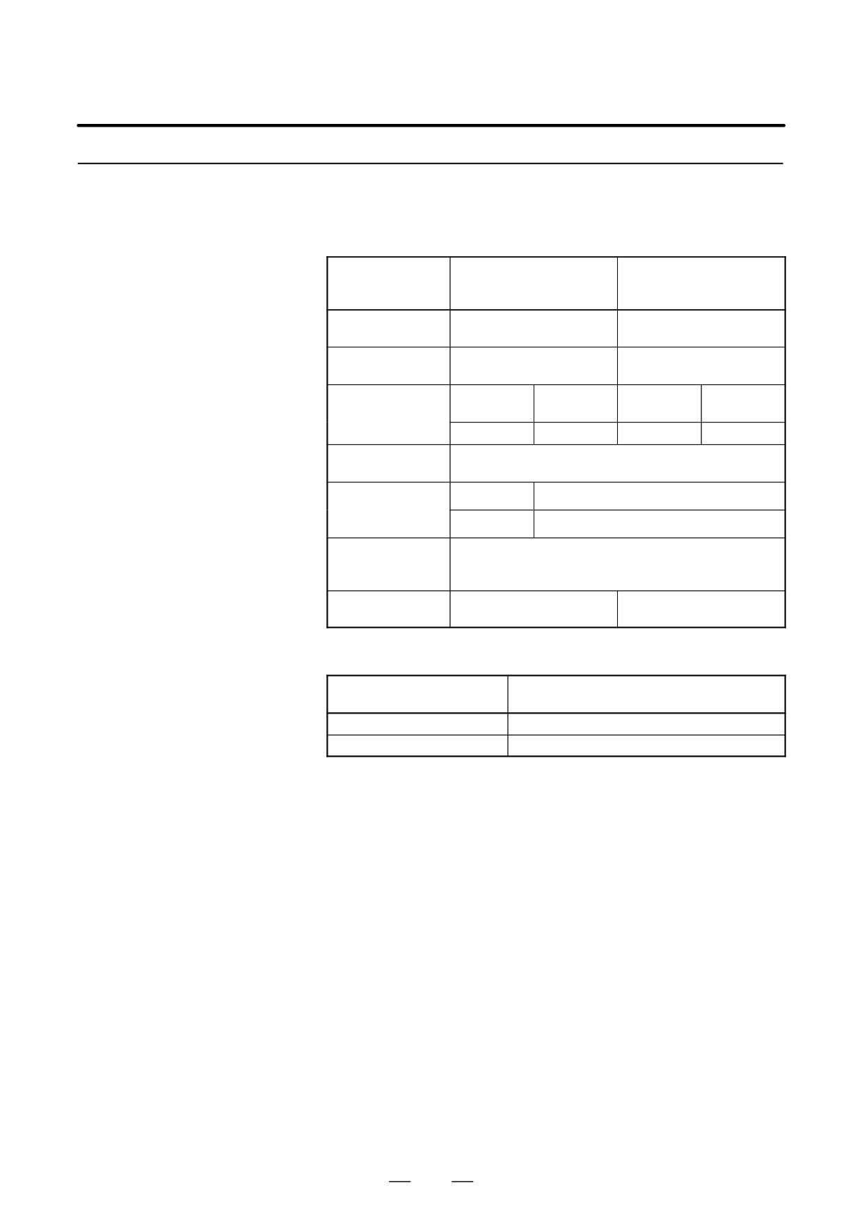
Specifications of Electromagnetic Contactors
A58L-0001-0306
A58L-0001-0312
FANUC purchase
(SC-3N manufactured
(SC-6N manufactured
code No.
by Fuji Electric)
by Fuji Electric)
Rated operating
220 V
220 V
voltage
Rated operating
65 A
125 A
current
Closed cir-
Closed cir-
Current capacity for
780A
1500A
cuit
cuit
the closed circuit
and shut-off
Shut-off
650A
Shut-off
1250A
Frequency
of
1200 times/hour or more
switching operation
Life expectancy of
Mechanical
5 million times or more
the switching op-
eration
Electrical
1 million times or more
Rating of the elec-
tromagnetic opera-
200/220 V, -15%, +10%, 50/60"1 Hz
tion coil
Applicable spindle
SPM-15 or less
SPM-30 or less
amplifier module
(2)
Specifications of the Relay
A58L-0001-0307
FANUC purchase code No.
(LY2-D manufactured by Omron)
Rated voltage
24V " 10%
Rated current
36.9 mA
542