FANUC SERVO AMPLIFIER a series. DESCRIPTIONS (B-65162E/03) - page 16
B-65162E/03
11. OPTION RELATED TO SPINDLE
11.1.2.4
Specifications
No.
Item
Description
Connected to a spindle on a one-to-one basis.
1
Position coder
1024 pulses/rev (phase A signal, phase B signal)
1 pulse/rev (one-rotation signal)
0.088_
One spindle rotation (360_) is divided by 1024
4 (4096) pulses, and one
2
Detection unit
pulse unit (0.088_) is used as the detection unit.
360_/ 4096 pulses = 0.088_/ pulses
"0.4_ (spindle angle)
This value does not include mechanical errors (such as the coupling back-
3
Positioning repeatability
lash between the spindle and position coder).
Depending on the position gain adjustment, an error of one detection unit
(0.088_) may occur after orientation.
Torque maintained at orienta-
4
None
tion stop time
Orientation of external stop
Enabled.
5
position setting type
However, the INDX signal is valid only with the 9D12 series.
Spindle orientation of incre-
6
Disabled
mental command type
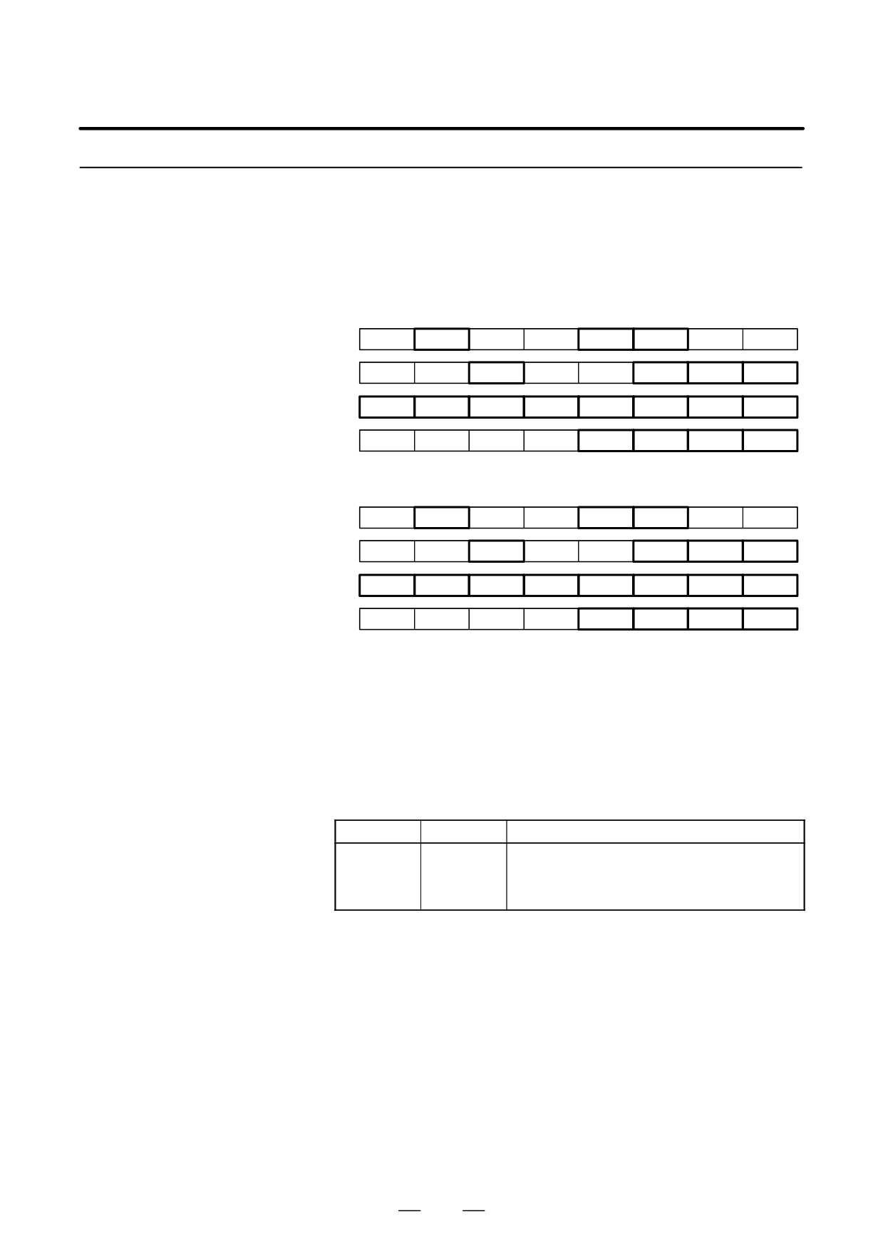
11.1.2.5
Signals
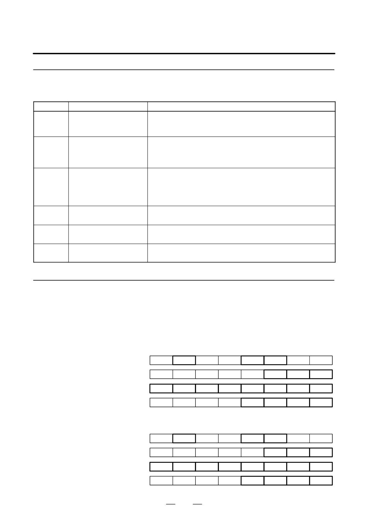
(1) Input Signals (PMC to CNC)
(a) Signal address
First spindle control input signal
FS0
FS15
FS16
#7
#6
#5
#4
#3
#2
#1
#0
: G229
G227
G070
MRDYA
ORCMA
SFRA
SRVA
CTH1A
CTH2A
TLMHA
: G231
G229
G072
OVRA
NRROA
ROTAA
INDXA
: G110
G231
G078
SHA07
SHA06
SHA05
SHA04
SHA03
SHA02
SHA01
SHA00
: G111
G230
G079
SHA11
SHA10
SHA09
SHA08
Second spindle control input signals
FS0
FS15
FS16
#7
#6
#5
#4
#3
#2
#1
#0
: G223
G235
G074
MRDYB
ORCMB
SFRB
SRVB
CTH1B
CTH2B
TLMHB
: G235
G237
G076
OVRB
NRROB
ROTAB
INDXB
: G112
G239
G080
SHB07
SHB06
SHB05
SHB04
SHB03
SHB02
SHB01
SHB00
: G113
G238
G081
SHB11
SHB10
SHB09
SHB08
453

11. OPTION RELATED TO SPINDLE
B-65162E/03
(b)
Orientation command (ORCMA)
D This signal is used to stop the spindle at a specified position to
attach/detach a workpiece.
D When this signal is set to 1, the spindle, if rotating, is decelerated
immediately and stops at a specified position.
D If an orientation command is issued for safety, set the spindle forward
rotation/reverse rotation command (SFRA/SFRA) to 0. Then, the
spindle does not start rotating even if ORCMA is set to 0 during tool
replacement.
D Ensure that this signal is set to 0 by the workpiece attachment /
detachment completion signal.
D Ensure that the orientation command signal is set to 0 when the power
is turned on.
D Reset the orientation command signal to 0 when an emergency stop is
initiated during orientation.
(c)
Clutch/gear signals (CTH1A, CTH2A)
D When there are two or more speed change gear stages between the
spindle and spindle motor, these signals are used to select a spindle
control parameter (position gain, gear ratio, velocity loop gain).
D Depending on the clutch or gear state, make settings according to the
table below. Names such as HIGH GEAR are given only for
convenience. Arbitrary names may be assigned to the actual gears.
CTH1A
CTH2A
0
0
HIGH GEAR
0
1
MEDIUM HIGH GEAR
1
0
MEDIUM LOW GEAR
1
1
LOW GEAR
(d)
Spindle orientation stop position change command (INDXA)
D In orientation of external stop position setting type, this signal is used
to orient the spindle to a different position immediately after spindle
orientation.
This signal is valid when the spindle orientation command (ORCMA)
is set to 1.
D When this signal makes a transition from 1 to 0, the spindle is oriented
within one rotation to the position specified by new stop position data
(SHA11 to SHA00) (arbitrary position within one rotation specified
by an absolute position command).
D The direction of orientation is specified by the shortcut rotation
command (NRROA) or rotation direction command (ROTAA).
D This function is enabled when the CNC parameter for an orientation
function of external stop position setting type is set.
(e)
Shortcut rotation command for spindle orientation stop position modification (NRROA)
D This signal is used to specify a rotation direction when the spindle is
oriented to a different position immediately after spindle orientation.
This signal is used for shortcut rotation (within "180_) to the next
stop position.
454
B-65162E/03
11. OPTION RELATED TO SPINDLE
D When this signal is set to 1, the spindle is oriented by shortcut rotation,
regardless of the specification of the rotation direction command for
spindle orientation stop position modification (ROTAA).
(f)
Rotation direction command for spindle orientation stop position modification (ROTAA)
D This signal is used to specify a rotation direction when the spindle is
oriented to a different position immediately after spindle orientation.
When this signal is set to 0, the spindle rotates counterclockwise and
stops.
When this signal is set to 1, the spindle rotates clockwise and stops.
D This signal is valid when the shortcut rotation command for spindle
orientation stop position modification (NRROA) is set to 0.
(g)
Spindle orientation external-type stop position command (SHA11 to SHA00)
D This signal is used to specify a stop position when the orientation
function of external stop position setting type is used. A stop position
is determined using the formula below. This command specifies an
absolute position within one rotation.
11
360
Stop position (degrees) +
ȍ
(2i
Pi)
4096
i+0
Note that Pi = 0 when SHAi =0, and Pi = 1 when SHAi = 1.
D When a spindle orientation function of external stop position setting
type is used, the parameter (parameter No. 4031 (FS16)) for setting a
stop position in spindle orientation of position coder type is disabled.
455

11. OPTION RELATED TO SPINDLE
B-65162E/03
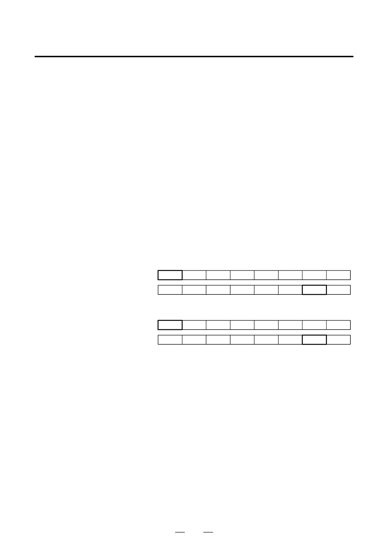
(2)
Output Signals (CNC to PMC)
(a)
Signal addresses
First spindle control output signal
FS0
FS15
FS16
#7
#6
#5
#4
#3
#2
#1
#0
1st
: F281
F229
F405
ORARA
TLMA
LDTA
SARA
SDTA
SSTA
ALMA
Second spindle control output signals
FS0
FS15
FS16
#7
#6
#5
#4
#3
#2
#1
#0
1st
: F285
F245
F049
ORARB
TLMB
LDTB
SARB
SDTB
SSTB
ALMB
(b)
Orientation completion signal (ORARA)
D This signal is set to 1 when the spindle stops near a specified position
(within "1_, for example) after an orientation command is entered.
ORARA is set to 1 when the following conditions are satisfied:
- ORCMA = 1
- Speed zero signal = 1
- The spindle stops near a specified position.
The third condition (near a specified position) is set using parameter
No. 4075 (FS16) for orientation completion signal detection level
specification. When all of the three conditions above are satisfied, the
orientation completion signal is output. If the orientation completion
signal is not issued despite sufficient time having elapsed after the
input of an orientation command, an error is assumed. Ensure that
such an error is detected with the power magnetics sequence, and that
an orientation alarm is issued.
D Only after this signal is set to 1, start workpiece attachment or
detachment.
D The orientation completion signal is output when the spindle is within
about "1_ of a specified position. This means that this signal does
not represent a complete stop.
D When the spindle is displaced from a point near a specified position
by an external force, this signal is set to 0.
456
B-65162E/03
11. OPTION RELATED TO SPINDLE
11.1.2.6
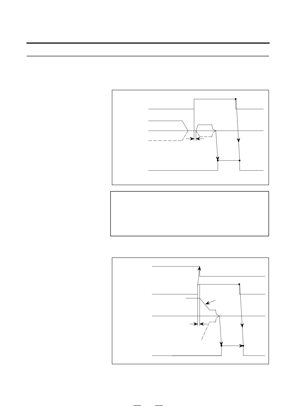
Sequence
(1) Orientation from Stop State
1
Orientation command
0
0
ORCMA
Stop
CW direction
Stop
Motor speed
CCW direction
15 to 20 ms
1
Orientation completion signal
0
0
ORARA
NOTE
The rotation direction of the spindle motor can be selected
by parameter setting. The standard setting stops the
spindle at a specified position after rotating the spindle in
the same direction as that before the command signal for
stopping the spindle at a specified position is issued.
(2) Orientation command during high-speed rotation
Rotation command
1
SFRA, SRVA
0
1
Orientation command
0
0
ORCMA
Deceleration
High-speed
CW direction
Stop
Motor speed
15 to 20 ms
CCW direction
1
Orientation completion signal
0
0
ORARA
457
11. OPTION RELATED TO SPINDLE
B-65162E/03
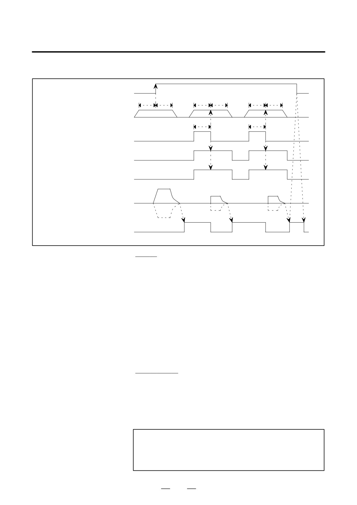
(3)
Orientation of external stop position setting type
Spindle orientation command
ORCMA
t
t
t
t
t
t
Spindle orientation stop posi-
tion command SHA00-11
t
t
Spindle orientation stop position
changing command INDXA
Rotating direction command
when spindle orientation stop
position is changed ROTAA
Shorter route command when
spindle orientation stop posi-
tion is changed NRROA
CW
direction
Stop
Stop
Stop
Motor speed
CCW direction
Spindle orientation completion
signal ORARA
Set t to 50msec or more.
Stop
D Spindle stop at a specified position by a normal orientation command
D The rotation direction of the spindle motor is specified by parameter
setting.
D After power-on, the spindle first stops at a specified position after
rotating at the orientation speed and reading a one-rotation signal.
After the first stop, the spindle turns within one rotation before
stopping at a specified position.
D When an orientation function of external stop position setting type is
used, the spindle stops at a specified position by shifting by the stop
position data read on the rising edge of the spindle orientation
command signal (ORCMA) if the data of the spindle orientation stop
position command (SHA00-SHA11) is determined for a second and
subsequent stop.
Stop and
D The spindle stops at a specified position according to an orientation
function of external stop position setting type.
D The rotation direction of the spindle motor depends on the rotation
direction command for spindle orientation stop position modification
(ROTAA) or the shortcut rotation command for spindle orientation
stop position modification (NRROA).
NOTE
The spindle orientation stop position change command
(INDXA) is enabled only when the spindle orientation
command (ORCMA) is set to 1.
458

B-65162E/03
11. OPTION RELATED TO SPINDLE
11.1.2.7
The table below lists the parameters used with an orientation function of
position coder type. For details of the parameters, see the parameter
Parameter List
manual.
Parameter No.
FS0
FS15
FS16
Description
First
Second
First
Second
spindle
spindle
spindle
spindle
Orientation function setting
Whether to use the spindle orientation function. (To be set to 1). (The
6515#0
6655#0
3015#0
3155#0
4015#0
CNC software option is required.)
0080
0080
5609
5609
3702
Whether to use the spindle orientation function of external stop position
#2
#3
#2
#3
#3,#2
setting type. (#2: First spindle, #3: Second spindle)
Setting related to the position coder signal
6501#2
6641#2
3001#2
3141#2
4001#2
Whether to use the position coder signal. (To be set to 1)
6500#2
6640#2
3000#2
3140#2
4000#2
Position coder mounting direction
6500#0
6640#0
3000#0
3140#0
4000#0
Spindle and motor rotation direction
6598
6738
3098
3238
4098
Position coder signal detection maximum speed
Gear ratio setting
6556 to
6696 to
3056 to
3196 to
4056 to
Gear ratio between the spindle and motor (to be selected with CTH1A
6559
6699
3059
3199
4059
and CTH2A)
Setting of a rotation direction at orientation time
6503
6643
3003
3143
4003
Rotation direction at spindle orientation time
#3,#2
#3,#2
#3,#2
#3,#2
#3,#2
Setting of a stop position shift amount
Stop position in orientation of position coder type (This parameter is ig-
6531
6671
3031
3171
4031
nored for orientation of external stop position setting type.)
6577
6717
3077
3217
4077
Spindle orientation stop position shift amount
Setting related to gain at orientation time
6560 to
6700 to
3060 to
3200 to
4060 to
Position gain at orientation time (to be selected with CTH1A and
6563
6703
3063
3203
4063
CTH2A)
6542
6682
3042
3182
4042
Velocity loop proportional gain at orientation time (to be selected with
6543
6683
3043
3183
4043
CTH1A)
6550
6690
3050
3190
4050
Velocity loop integral gain at orientation time (to be selected with
6551
6691
3051
3191
4051
CTH2A)
6554
6694
3054
3194
4054
Velocity loop incomplete integral coefficient at orientation time
6579
6719
3079
3219
4079
Position gain broken line speed at orientation time
6584
6724
3084
3224
4084
Motor voltage setting at spindle orientation time
6592 to
6732 to
3092 to
3232 to
4092 to
Orientation deceleration constant (to be selected with CTH1A/1B,
6595
6735
3095
3235
4095
CTH2A/2B).
Setting related to orientation speed
6576
6716
3076
3216
4076
Motor speed limit ratio at spindle orientation time
6538
6678
3038
3178
4038
Spindle orientation speed
459

11. OPTION RELATED TO SPINDLE
B-65162E/03
Parameter No.
FS0
FS15
FS16
Description
First
Second
First
Second
spindle
spindle
spindle
spindle
Setting related to the orientation completion signal
6575
6715
3075
3215
4075
Spindle orientation completion signal detection level
Others
6517#7
6657#7
3017#7
3157#7
4017#7
Shortcut rotation function for orientation from stop state
11.1.3
Spindle Orientation of
Incremental Command
Type (Spindle Speed
Control)
11.1.3.1
The spindle orientation function of incremental command type is an
extended function of the spindle orientation function of external stop
Overview
position setting type based on a position coder.
This function moves the spindle to a position specified by an incremental
command from the position where the spindle is placed when a spindle
orientation command is entered. That is, from the position where the
spindle is placed when a spindle orientation command is entered, the
spindle rotates by the amount specified by an incremental command
issued from the PMC through the CNC. Upon the completion of
positioning, the completion signal is returned to the PMC through the
CNC. This function enables the following:
D Operations such as turret indexing using a spindle motor.
D The speed of the spindle can be controlled by setting the command
multiplier (parameter setting value) to 4096.
NOTE
This function is not available with the αC series spindle.
460
B-65162E/03
11. OPTION RELATED TO SPINDLE
11.1.3.2
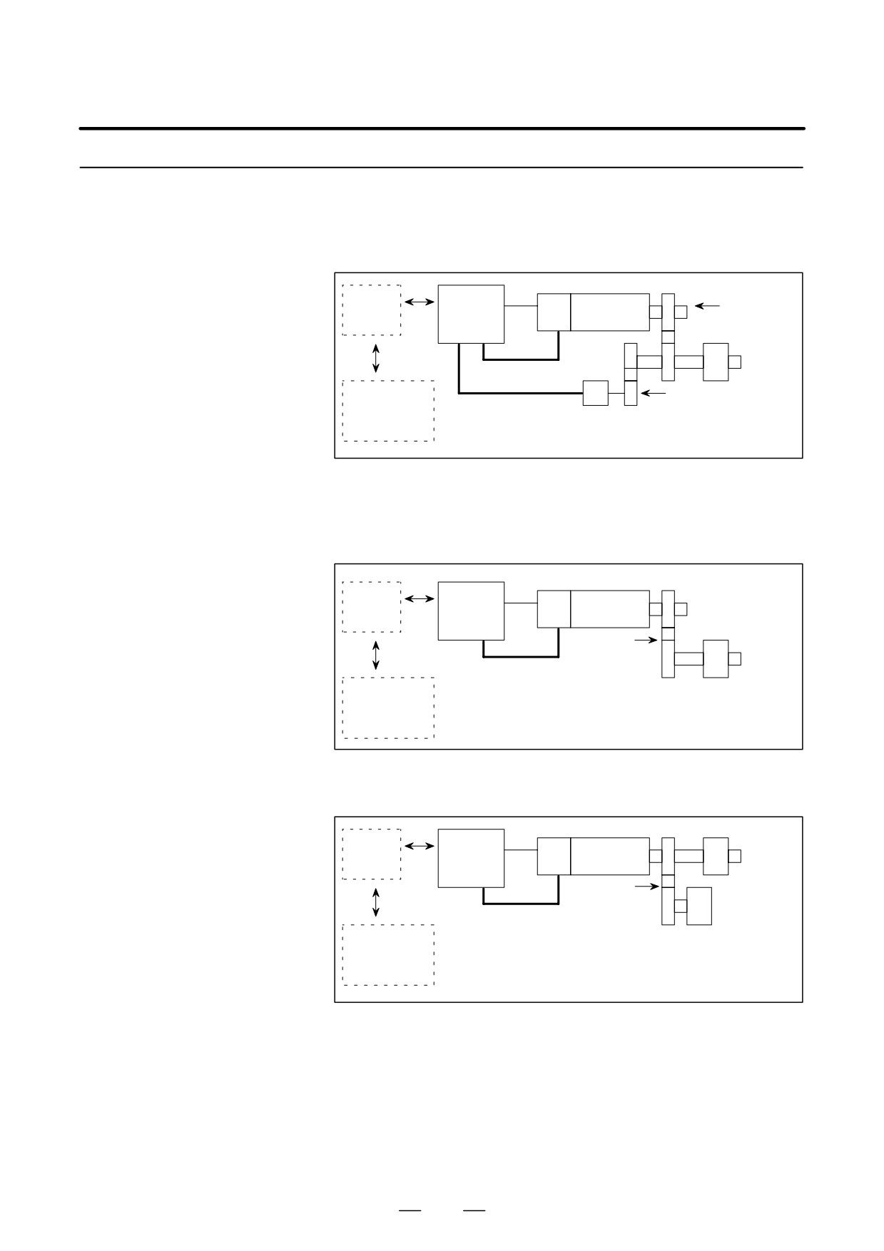
The spindle orientation function with the incremental command set
externally can be executed in the following system configurations:
System Configurations
D System in which the position coder is linked to the spindle
Spindle
Gear or
CNC
Spindle
amplifier
belt
motor
(SPM)
Spindle
Velocity feedback
Power
Directly connected,
magnetics
Position feedback
gear or timing belt
sequence
Position coder
(1:1)
circuit
D Motor system built into the spindle
D System in which the spindle and the motor having a MZ sensor are
linked by a gear or timing belt
Spindle
Spindle motor
CNC
amplifier
with MZ sen-
sor
(SPM)
Spindle
Gear or
timing belt
Velocity and position
feedback
Power
magnetics
sequence
circuit
D System in which the turret and the motor having a MZ sensor are
linked by gears and clutches (for turret positioning)
Gear Spindle
Spindle
Spindle motor
CNC
amplifier
with MZ sen-
sor
(SPM)
Linked
by a
Turret
Velocity and position
clutch
Power
feedback
magnetics
sequence
circuit
461
11. OPTION RELATED TO SPINDLE
B-65162E/03
11.1.3.3
Signals
(1)
Input Signals (PMC to CNC)
(a)
Signal address
First spindle control input signal
FS0
FS15
FS16
#7
#6
#5
#4
#3
#2
#1
#0
: G229
G227
G070
MRDYA
ORCMA
SFRA
SRVA
CTH1A
CTH2A
TLMHA
TLMLA
: G231
G229
G072
RCHHGA
MFNHGA
INCMDA
OVRA
DEFMDA
NRROA
ROTAA
INDXA
: G110
G231
G078
SHA07
SHA06
SHA05
SHA04
SHA03
SHA02
SHA01
SHA00
: G111
G230
G079
SHA11
SHA10
SHA09
SHA08
Second spindle control input signals
FS0
FS15
FS16
#7
#6
#5
#4
#3
#2
#1
#0
: G223
G235
G074
MRDYB
ORCMB
SFRB
SRVB
CTH1B
CTH2B
TLMHB
TLMLB
: G235
G237
G076
RCHHGB
MFNHGB
INCMDB
OVRB
DEFMDB
NRROB
ROTAB
INDXB
: G112
G239
G080
SHB07
SHB06
SHB05
SHB04
SHB03
SHB02
SHB01
SHB00
: G113
G238
G081
SHB11
SHB10
SHB09
SHB08
(b)
Orientation command signal (ORCMA)
A spindle orientation function of external incremental command setting
type is enabled during spindle orientation.
1: Performs orientation.
(c)
Clutch/gear signals (CTH1A, CTH2A)
These signals are used to select a spindle control parameter (position gain,
gear ratio, velocity loop gain) that matches a selected clutch/gear. Names
such as High Gear are assigned only for convenience.
CTH1A
CTH2A
Gear/clutch state
0
0
High Gear
(High)
0
1
Medium High Gear
(High)
1
0
Medium Low Gear
(Low)
1
1
Low Gear
(Low)
(d)
Incremental command data selection signal (INCMDA)
This signal is used to determine whether externally set data
(SHA00-SHA11) is used as stop position data or incremental command
data.
0: Uses SHA00-SHA11 as stop position data.
1: Uses SHA00-SHA11 as incremental command data.
(e)
Shortcut rotation command (NRROA)
When stop position data is selected (INCMDA = 0) for stop position
modification, this signal rotates the spindle in the shortcut direction to the
target position. This signal is invalid when INCMDA = 1.
0:Rotates the spindle in the direction based on the parameter setting
(bits 2 and 3 of parameter No. 4003 (FS16) and ROTAA state.
462
B-65162E/03
11. OPTION RELATED TO SPINDLE
1:Rotates the spindle in the shortcut direction.
(f)
Rotation direction command signal (ROTAA)
This signal is used to specify the direction in which the spindle is rotated
from the stop state to another stop position.
0: Rotates the spindle counterclockwise.
1: Rotates the spindle clockwise.
(g)
Stop position change command signal (INDXA)
This signal is used to change the stop position. On the rising edge of this
signal, INCMDA, ROTAA, and stop position (incremental command)
data are read.
1 → 0: Stop position change command
(h)
Incremental command data (stop position data) (SHA11 to SHA00)
These signals (12 bits) are used to specify incremental command data or
stop position data. INCMDA determines which data to use. A command
of 0 to +4095 pulses can be entered.
(2)
Output Signals (CNC to PMC)
(a)
Signal addresses
First spindle control output signal
FS0
FS15
FS16
#7
#6
#5
#4
#3
#2
#1
#0
: F281
F229
F405
ORARA
TLMA
LDT2A
LDTA
SARA
SDTA
SSTA
ALMA
: F283
F221
F047
EXOFA
SORENA
MSOVRA
INCSTA
PC1DTA
Second spindle control output signals
FS0
FS15
FS16
#7
#6
#5
#4
#3
#2
#1
#0
: F285
F245
F049
ORARB
TLMB
LDT2B
LDT1B
SARB
SDTB
SSTB
ALMB
: F287
F247
F051
EXOFB
SORENB
MSOVRB
INCSTB
PC1DTB
(b)
Orientation completion signal (ORARA)
This signal is used to indicate the orientation completion state. This
signal is output when the following three conditions are satisfied:
a. The spindle is near a specified stop position
(in-position)
(parameter No. 4075 (FS16).
b. The spindle is being oriented (ORCMA = 1).
c. The spindle is in the speed zero state (SSTA = 1).
(c)
Incremental command mode state signal (INCSTA)
This signal is used to indicate the state of INCMDA (incremental
command data selection signal).
1: INCMDA = 0
0: INCMDA = 1
463
11. OPTION RELATED TO SPINDLE
B-65162E/03
11.1.3.4
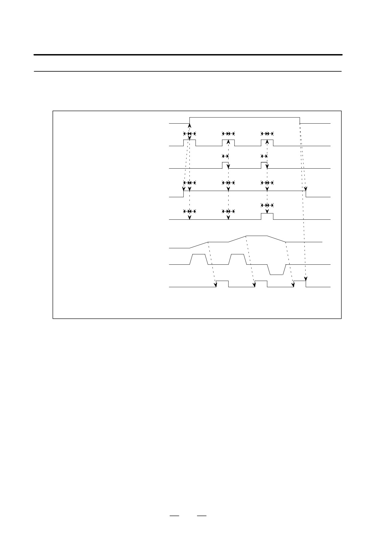
Control Sequence
(1)
Incremental Action
ORCMA
(Spindle orientation command)
t
t
t
t
t
t
SHA00 to SHA11 (Command for
specifying the stop position in spindle
orientation)
t
t
INDXA
(Command for changing the stop posi-
tion in spindle orientation)
t
t
t
t
t
t
INCMDA
(Command for selecting stop position
data or incremental command data)
t
t
ROTAA
t
t
t
t
(Command for specifying the direction of
rotation when changing the stop position)
(Note)To confirm the signal, t should be 50 msec or more.
Spindle position
CCW
CCW
Motor speed
CW
ORARA
(Orientation completion signal)
Notes
Set t to 50 ms or more. The signals require this time period to stabilize.
If the rising edge of ORCM is detected when the spindle stops (zero
speed detection signal SSTA is set to 1) and INCMDA is set to 1, the data
of SHA00 to SHA11 is read as incremental command data. The spindle
starts rotating as specified by the incremental command and stops.
ROTAA determines the direction of rotation.
Another incremental action can then be executed. If the falling
edge of INDXA is detected when both ORCM and INCMDA are
set to 1, the data of SHA00 to SHA11 is read as incremental
command data. The spindle starts rotating as specified by the
incremental command and stops. ROTAA determines the direction
of rotation.
The incremental command data is specified in units of pulses. The
data range is 0 to +4095 pulses. ROTAA determines the direction
of rotation. When a command multiplication parameter (Series 16:
PRM4328) is specified, the spindle stops rotating after reaching the
value obtained by the following expression:
[Command
multiplication parameter]
[Incremental command data]. During
incremental motion, the parameter indicating the direction of
rotation, NRROA (Series 16: PRM4003, bits 2 and 3), is invalid.
When the position error comes within the range specified by the
parameter (Series 16: PRM4075), ORARA is output.
464
B-65162E/03
11. OPTION RELATED TO SPINDLE
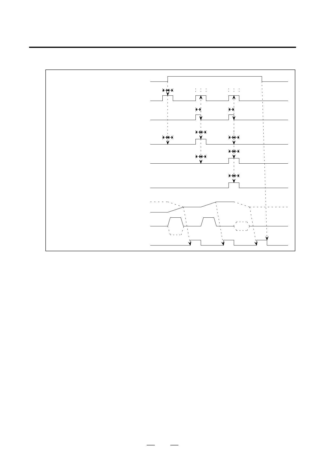
(2)
When Spindle Orientation and Incremental Motion are both Executed
ORCMA
(Spindle orientation command)
t
t
t t
t t
SHA00 to SHA11 (Command for specifying
the stop position in spindle orientation)
t
t
INDXA
(Command for changing the stop position
in spindle orientation)
t
t
t
t
t
t
INCMDA
(Command for selecting stop position data
or incremental command data)
t
t
t
t
ROTAA
(Command for specifying the direction of
rotation when changing the stop position)
t
t
NRROA
(Command for taking a shorter route when
changing the stop position)
Spindle position
CCW
Motor speed
ORARA
(Orientation completion signal)
Stopping the spindle in place using the usual orientation command
Z In the first orientation after the power is turned on, the spindle
rotates at the orientation speed. After a one rotation signal is
detected, the spindle stops in place. In the second and
subsequent orientations, the spindle stops in place within
rotation
Z The parameter specifying the direction of rotation (Series 16:
PRM4003, bits 2 and 3) applies to the spindle motor.
Z If the rising edge of ORCMA is detected when INCMDA is set
to 0, the data of SHA00 to SHA11 is read as stop position data.
The spindle stops after shifting by the distance obtained by the
following expression:
[Value of SHA00 to SHA11]
+
[Parameter of shift distance of the stop position in orientation
(Series 16: PRM4077)]
Stopping the spindle in place by an incremental command
Z For incremental motion, see item ” Incremental action” above.
Z When the command multiplication parameter (Series 16:
PRM4328) is set to 4096, the spindle rotation can be controlled.
Stopping the spindle in place by setting the stop position externally
Z If the falling edge of INDXA is detected when ORCMA is set
to 1 and INCMDA is set to 0, the data of SHA00 to SHA11 is
read as stop position command data. The spindle rotates and
stops at the specified position.
465
11. OPTION RELATED TO SPINDLE
B-65162E/03
Z NRROA and ROTAA determine the direction of rotation.
When NRROA is set to 1, the spindle rotates from the current
stop position to the specified stop position by taking the shorter
route (within "180°). When NRROA is set to 0, ROTAA
determines the direction of rotation.
11.1.3.5
The following parameters are added when the function for externally
setting incremental commands is used for position coder method spindle
Parameters
orientation Refer to the Parameter Manual and each CNC manual for
details.
Parameter No.
Description
FS0
FS15
FS16
0080
5609
3702
Whether the function for externally setting incremental commands is
#3, 2
#3, 2
#3, 2
used (#2: First spindle, #3: Second spindle)
Command multiplication for data for externally setting incremental com-
6292
3472
4328
mands
11.1.4
Spindle Orientation by
External One Rotation
Signal
11.1.4.1
This section describes a spindle orientation function. This function is
implemented in a system consisting of an external one-rotation signal
General
switch (proximity switch) mounted on the spindle, and a spindle motor
having a built-in sensor and connected to the spindle with an arbitrary
gear ratio.
This function is similar to the position coder-based spindle orientation
function except for the items listed below.
1) A fixed orientation must be specified by setting 1 in bit 3 of parameter
No. 4003.
2) The detection of a one-rotation signal begins after the orientation
speed is reached.
NOTE
1
See Section 11.1.1 for descriptions about anything other
than external one-rotation signal handling (position coder
- based spindle orientation).
2
The αC series does not support this function.
466
B-65162E/03
11. OPTION RELATED TO SPINDLE
11.1.4.2
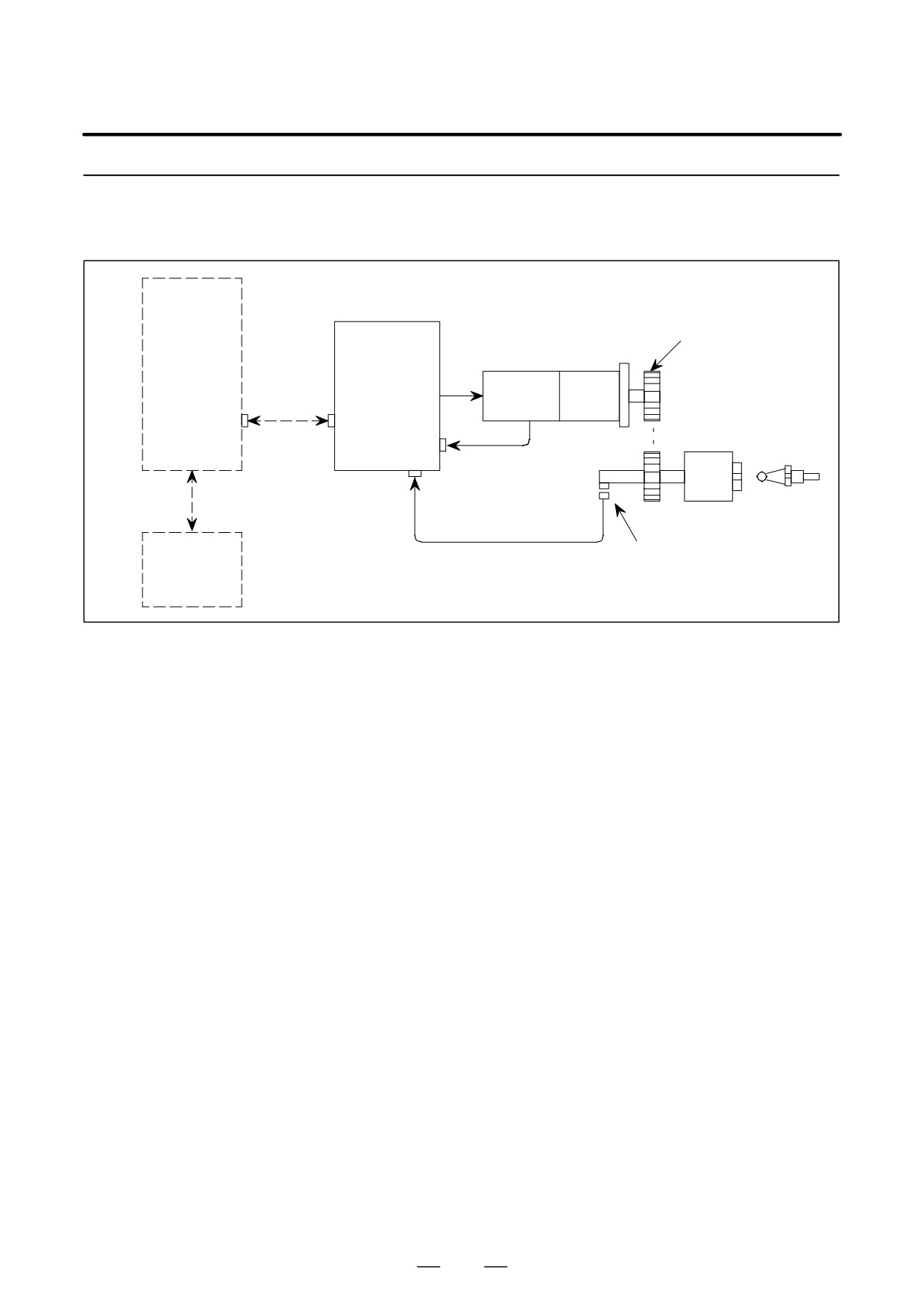
System Configuration
Gear or timing belt
Spindle
amplifier
CNC
(SPM)
Communica-
MZ
Spindle
tion cable
sensor
motor
JA7B
Spindle
JY2
Tool
Speed and position
JY3
feedback
Å
External one-rotation
Proximity switch (1:1)
PMC
signal
467
11. OPTION RELATED TO SPINDLE
B-65162E/03
11.1.4.3
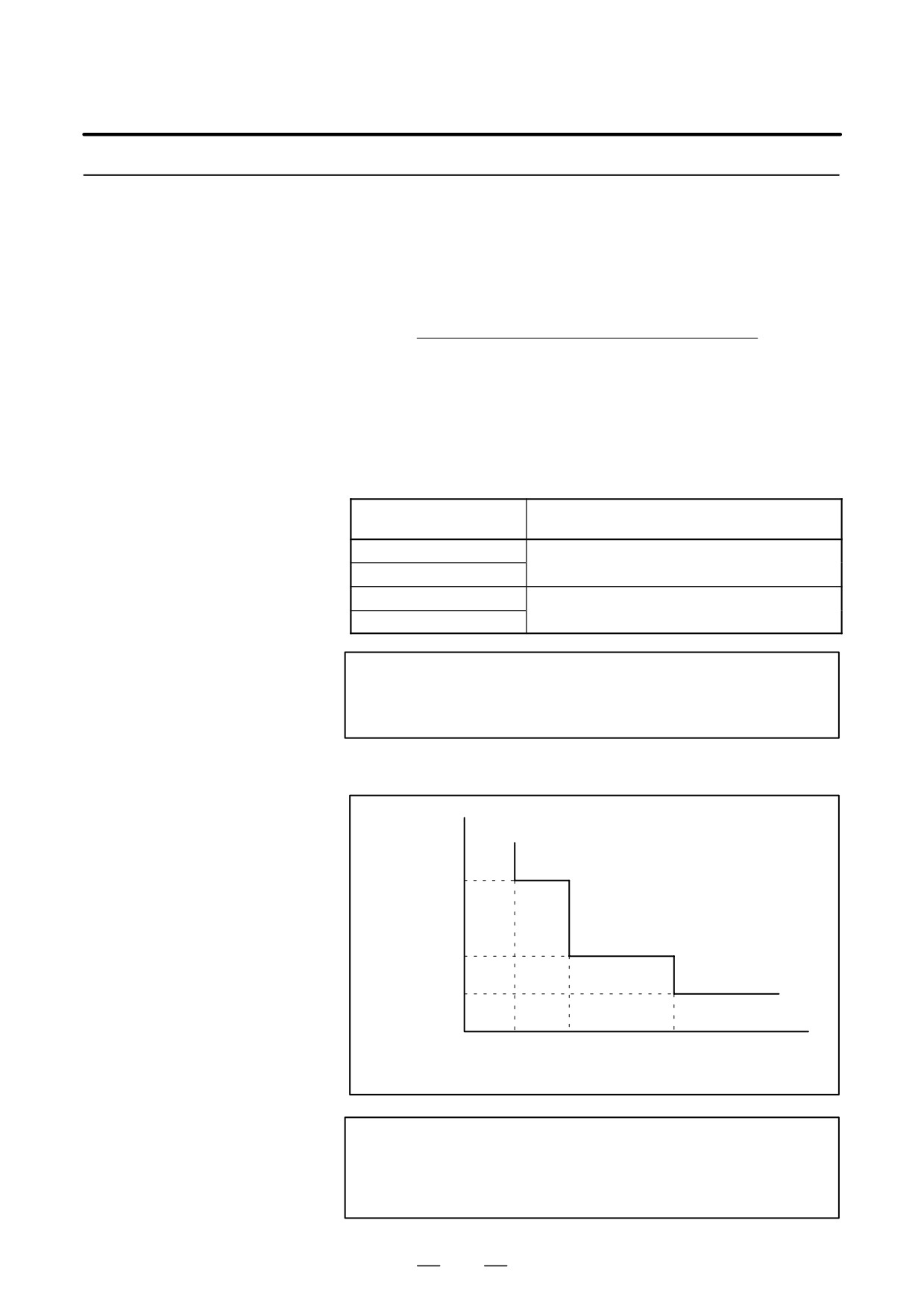
(1) Positioning repeatability
Specifications
When the spindle is connected to the spindle motor with an arbitrary
gear ratio of m:n, the positioning repeatability is calculated as
follows:
(χ = factor used to determine positioning repeatability)
(spindle-to-motor rotation ratio = m:n)
1024
m
χ=
(number of feedback pulses per motor rotation
n
(where χ is rounded up to the nearest integer.)
Positioning repeatability = "( χ
0.2) [°]
(Reference)
The table below lists the relationships between the number of
detected gear teeth per rotation and the number of feedback pulses
per motor rotation.
Number of detected gear
Number of feedback pulses per motor
teeth per rotation
rotation
512 teeth
1024
256 teeth
128 teeth
512
64 teeth
NOTE
These values exclude influence by the machine and the
external one-rotation signal switch.
(Reference)
Positioning
repeatability [°]
"0.8
"0.4
"0.2
Number of feedback
0
256
512
1024
pulses per spindle
rotation (Note)
NOTE
n
number of feedback pulses
= number of feedback
m
per spindle rotation
pulses per motor
rotation
468
B-65162E/03
11. OPTION RELATED TO SPINDLE
Example of calculation
(1)
Number of feedback pulses per motor rotation = 1024
Spindle-to-motor speed ratio (m/n) = 1:3 (speed reduction)
1
χ=1024
1024
3+0.3
Thus, χ is rounded up to 1.
Hence, positioning repeatability = "(1 x 0.2) = "0.2°
(2)
Number of feedback pulses per motor rotation = 512
Spindle-to-motor speed ratio (m/n) = 2:1 (speed up)
2
χ=1024
512
1+4
Thus, χ = 4
Hence, positioning repeatability = "(4 x 0.2) = "0.8°
(3)
Number of feedback pulses per motor rotation = 512
Spindle-to-motor speed ratio (m/n) = 1:2 (speed reduction)
1
χ= 1024
512
2+1
Thus, χ = 1
Hence, positioning repeatability = "(1 x 0.2) = "0.2°
(4)
Number of feedback pulses per motor rotation = 512
Spindle-to-motor speed ratio (m/n) = 1:1
1
χ= 1024
512
1+2
Thus, χ = 2
Hence, positioning repeatability = "(2 x 0.2) = "0.4°
469
11. OPTION RELATED TO SPINDLE
B-65162E/03
11.1.4.4
Signals
(1)
Input Signals (PMC to CNC)
(a)
Signal address
First spindle control input signal
FS0
FS15
FS16
#7
#6
#5
#4
#3
#2
#1
#0
: G229
G227
G070
MRDYA
ORCMA
SFRA
SRVA
CTH1A
CTH2A
TLMHA
TLMLA
: G110
G231
G078
SHA07
SHA06
SHA05
SHA04
SHA03
SHA02
SHA01
SHA00
: G111
G230
G079
SHA11
SHA10
SHA09
SHA08
Second spindle control input signals
FS0
FS15
FS16
#7
#6
#5
#4
#3
#2
#1
#0
: G223
G235
G074
MRDYB
ORCMB
SFRB
SRVB
CTH1B
CTH2B
TLMHB
TLMLB
: G112
G239
G080
SHB07
SHB06
SHB05
SHB04
SHB03
SHB02
SHB01
SHB00
: G113
G238
G081
SHB11
SHB10
SHB09
SHB08
(b)
Spindle orientation command (ORCMA)
1: Performs spindle orientation.
(c)
Clutch/gear signals (CTH1A, CTH2A)
These signals are used to select a spindle parameter (position gain,
velocity loop gain, and so forth). Names such as High gear are assigned
only for convenience.
CTH1A
CTH2A
Gear/clutch state
0
0
High Gear
(High)
0
1
Medium High Gear
(High)
1
0
Medium Low Gear
(Low)
1
1
Low Gear
(Low)
(d)
Stop position data (SHA11 to SHA00)
These signals are used to specify stop position data when the spindle is
oriented with a spindle orientation function of external stop position type.
Stop position data is read on the rising edge of ORCMA.
470

B-65162E/03
11. OPTION RELATED TO SPINDLE
(2) Output Signals (CNC to PMC)
(a) Signal addresses
First spindle control output signal
FS0
FS15
FS16
#7
#6
#5
#4
#3
#2
#1
#0
: F281
F229
F405
ORARA
TLMA
LDT2A
LDT1A
SARA
SDTA
SSTA
ALMA
Second spindle control output signals
FS0
FS15
FS16
#7
#6
#5
#4
#3
#2
#1
#0
: F285
F245
F049
ORARB
TLMB
LDT2B
LDT1B
SARB
SDTB
SSTB
ALMB
(b) Spindle orientation completion signal (ORARA)
This signal is used to indicate the spindle orientation completion state.
This signal is set to 1 when the following three conditions are satisfied:
a. The spindle is being oriented (ORCMA = 1).
b.The spindle is in the speed zero state (SSTA = 1).
c. The spindle is near a specified stop position (in-position).
471
11. OPTION RELATED TO SPINDLE
B-65162E/03
11.1.4.5
Control Sequence
ORCMA
(Spindle orientation
command)
t
t
SHA00-11
(Stop position
command for spindle
orientation)
EXTSC
(External one-
rotation signal)
Start of 1-rotation signal detection
After arrival of orientation speed
One-rotation signal detection
Orientation speed
Motor speed
ORARA
(Spindle orientation
completion signal)
NOTE
To confirm the signal, t should be 50 msec or more.
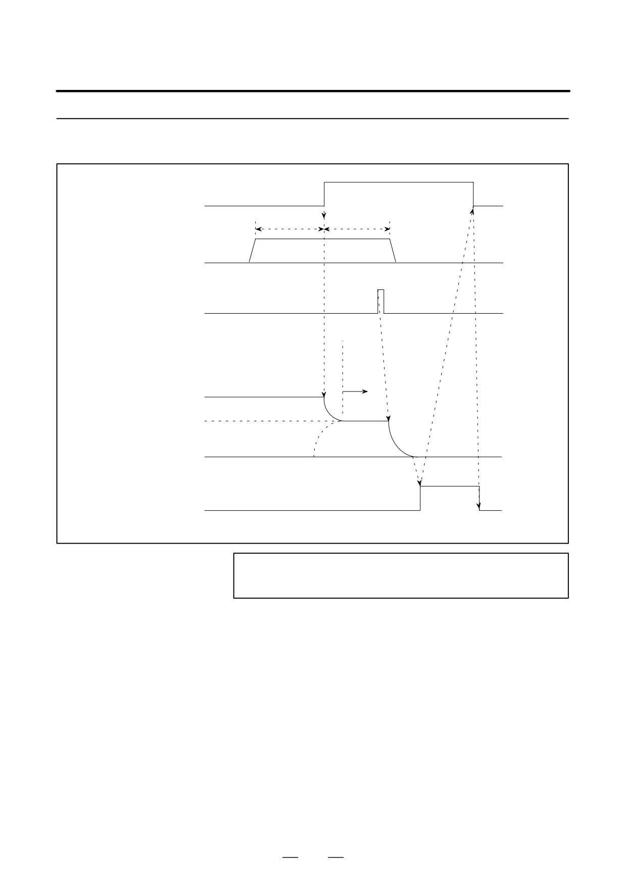
(1) Orientation function
D To detect a one-rotation signal securely, it is necessary to fix the
orientation (by setting bit 3 andt 2 of parameter No. 4003 to 1, 0 or
1, 1; see descriptions about parameter setting).
D After the orientation of the spindle is fixed and the orientation speed
is reached, a one-rotation signal is detected to cause the spindle to
stop at a position determined by the following stop position data
(Series16:4077).
Stop position data is (parameter No. 4031 + 4077)
Case of external stop position setting type, Stop position data is
(SHA00-11 + 4077)
D The orientation resolution of the spindle is 1/4096 rev (4096p/rev).
D If the stop position data (No. 4031 + No. 4077) or (SHA00-11 + No.
4077) is 0, the spindle stops at the edge of the output signal from the
one-rotation signal switch.
472
B-65162E/03
11. OPTION RELATED TO SPINDLE
11.1.4.6
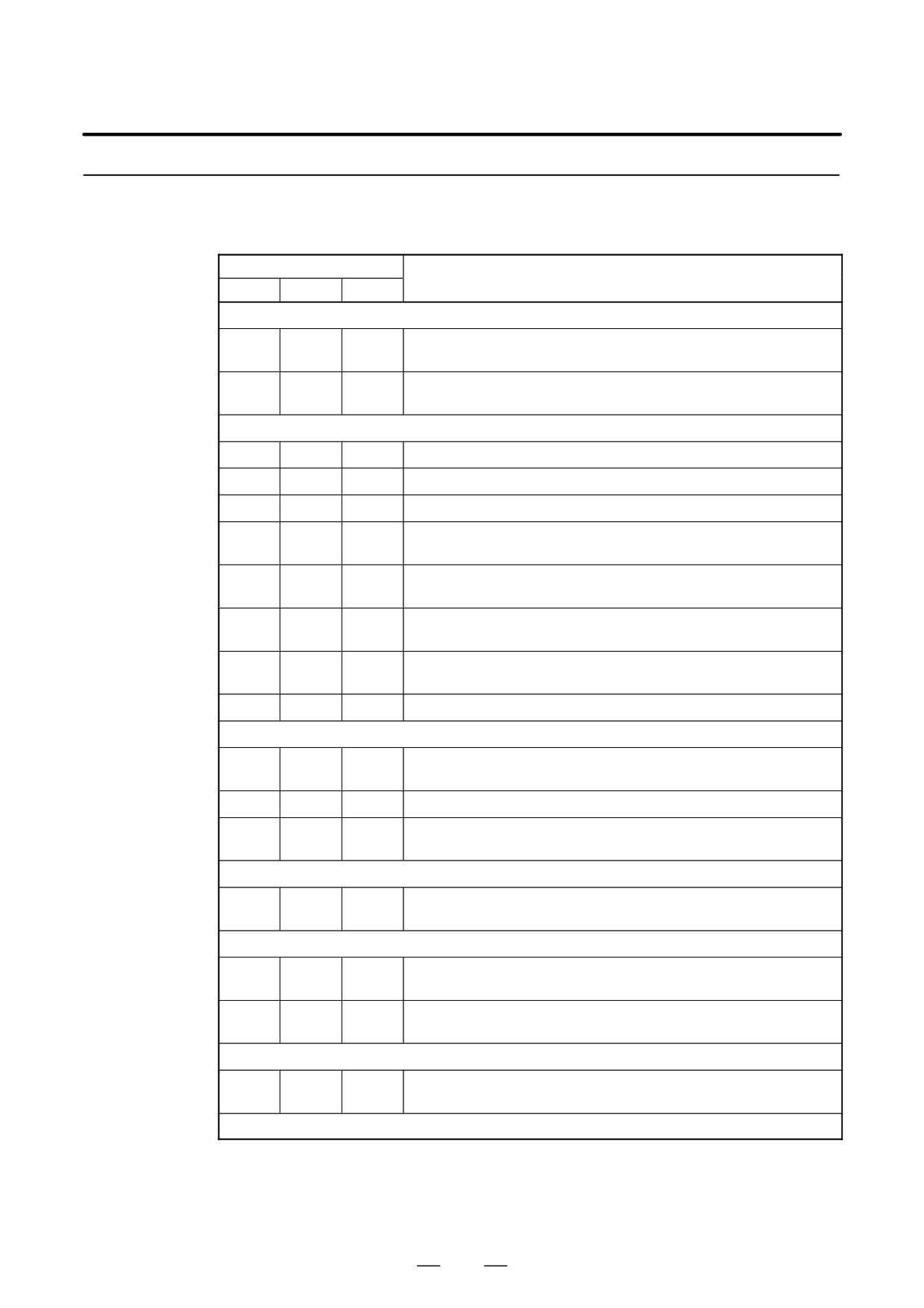
The table blow lists the parameters used with the spindle orientation
function based on the external one-rotation signal. For details of the
Parameters List
parameters, see the parameter manual.
Parameter No.
Description
FS0
FS15
FS16
Orientation function setting
Whether spindle orientation is used (Set to 1.)
6515#0
3015#0
4015#0
(CNC software option is necessary.)
0080
5609
3702
Whether to use the spindle orientation function of external stop position
#3,#2
#3,#2
#3,#2
setting type. (#2: First spindle, #3: Second spindle)
Setting related to the position coder signal
6501#2
3001#2
4001#2
Whether a position coder signal is used (Set to 1.)
6500#2
3000#2
4000#2
Mounting orientation for the position coder
6500#0
3000#0
4000#0
Rotational direction of the spindle and motor
Selection of position coder method or magnetic sensor method spindle
6503#0
3003#0
4003#0
orientation (0 for a position coder method)
6503
3003
4003#
Setting of the position coder signal
#7, 6, 4
#7, 6, 4
7, 6, 4
Setting of a position coder one-rotation signal detection edge. (To be
6513#0
3013#0
4013#0
set to 1)
Position coder one-rotation signal detection function in normal rotation.
6517#2
3017#2
4017#2
(To be set to 0)
6598
3098
4098
Position coder signal detection maximum speed
Setting related to the external one-rotation signal
Setting of reverse/nonreverse rotation of the external one-rotation sig-
6504#3
3004#3
4004#3
nal
6504#2
3004#2
4004#2
Whether to use the external one-rotation signal. (To be set to 1)
Setting of orientation based on the external one-rotation signal. (To be
6509#3
3009#3
4009#3
set to 1)
Gear ratio setting
6556 to
3056 to
4056 to
Gear ratio between the spindle and motor
6559
3059
4059
(selected by DI signals CTH1A and CTH2A)
Setting of an arbitrary gear ratio between the spindle and position coder
6935
3315
4171
Number of gear teeth on the spindle side. (A parameter is selected with
6937
3317
4173
input signal CTH1A).
6936
3316
4172
Number of gear teeth on the position detector side. (A parameter is se-
6938
3318
4174
lected with input signal CTH1A.)
Setting of a rotation direction at orientation time
6503
3003
4003
Rotation direction at orientation time
#3, #2
#3, #2
#3, #2
Setting of a stop position shift amount
473
11. OPTION RELATED TO SPINDLE
B-65162E/03
11.1.4.7
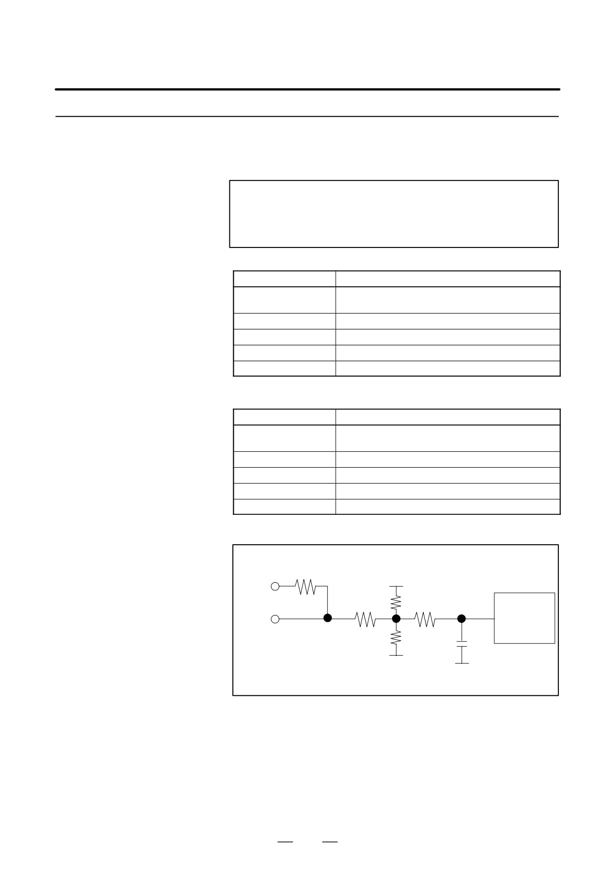
The external one-rotation signal switch (proximity switch) should satisfy
the following conditions.
Specification of the
External One-rotation
(1) Two-wire DC proximity switch
Signal Switch
NOTE
The proximity switch depends on the temperature. So,
when selecting an proximity switch, consider the ambient
temperature.
Item
Specification
Supply voltage
24 VDC "1.5 V (24 VDC is supplied from the spindle
amplifier module.)
Response frequency
400 Hz or higher
Load current
16 mA or higher
Residual voltage
4 V or lower
Drain (leakage) current
1.5 mA or lower
(2) Three-wire DC proximity switch
Item
Specification
Supply voltage
24 VDC "1.5 V (24 VDC is supplied from the spindle
amplifier module.)
Response frequency
400 Hz or higher
Load current
16 mA or higher
Residual voltage
4 V or lower
Drain current
50 mA or lower
(3) Receiver circuit
3.4k
24V
PU/PD
91k
39k
2k
Level
EXTSC
converter
75k
330pF
Level L:
0V
EXTSC<4V
0V
Level H :
EXTSC>17V
474
B-65162E/03
11. OPTION RELATED TO SPINDLE
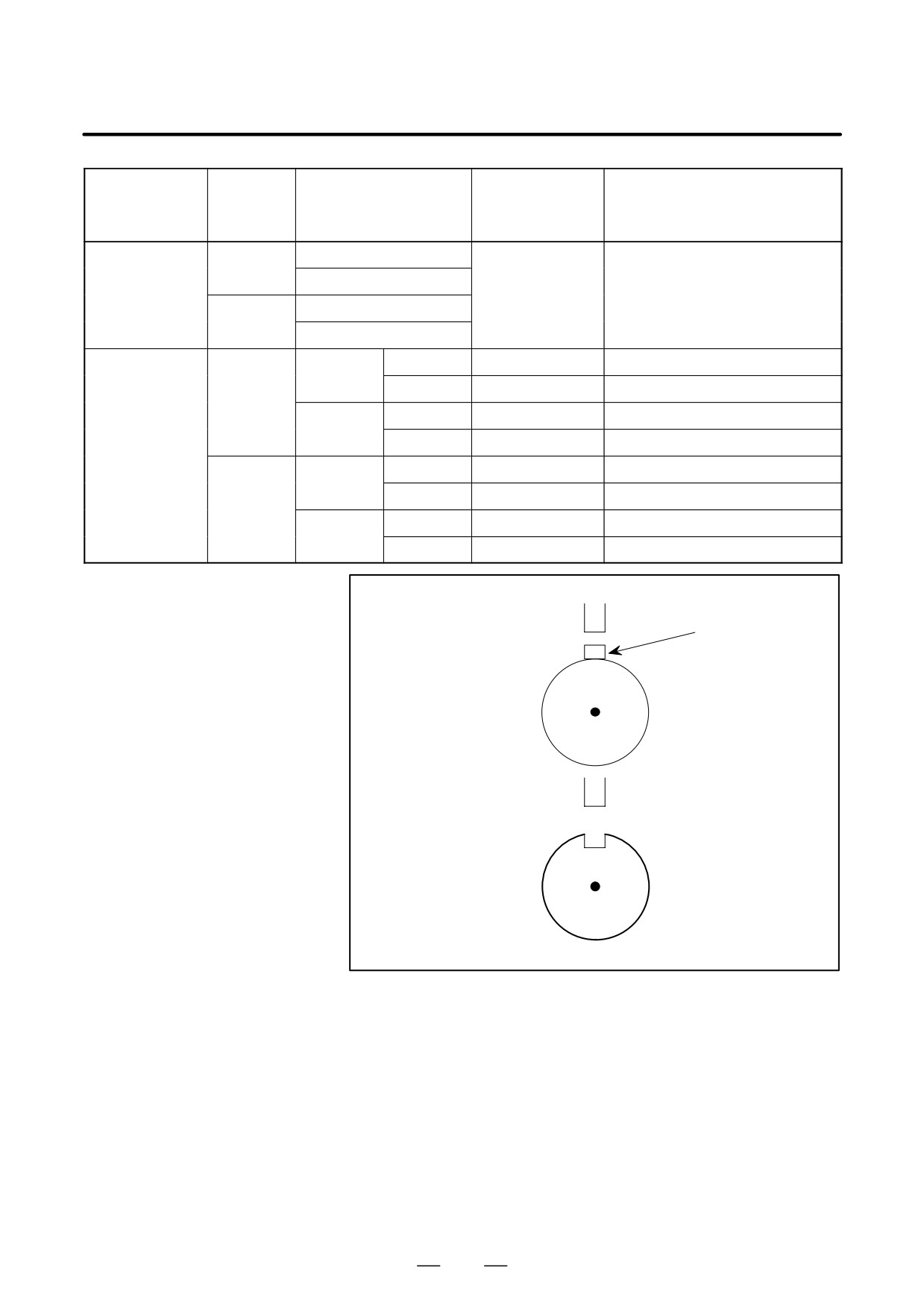
Parameters
Detection
PU/PD pin of
Bit 3 of parameter No. 4004 (FS16)
Proximity switch
Proximity switch type
method
connector JY3
Bit 3 of parameter No. 3004 (FS15)
Bit 3 of parameter No. 6504 (FS0)
Normally open
Convex
detection
Normally closed
Two–wire type
Connected to 24V
0
Normally open
Concave
detection
Normally closed
NPN
Connected to 24V
0
Normally
open
PNP
Connected to 0V
1
Convex
detection
NPN
Connected to 24V
1
Normally
closed
PNP
Connected to 0V
0
Three–wire type
NPN
Connected to 24V
0
Normally
open
PNP
Connected to 0V
1
Concave
detection
NPN
Connected to 24V
1
Normally
closed
PNP
Connected to 0V
0
Convex detection:
Proximity switch
Object detected
Å
Å
Spindle
Concave detection:
Proximity switch
Spindle
475

11. OPTION RELATED TO SPINDLE
B-65162E/03
11.1.4.8
Notes
(1) Ensure that the spindle orientation command (ORCMA) is set to 0
when the power is turned on.
(2) For safety, set the forward/reverse rotation command (SFRA/SRVA)
and speed command to 0 when performing spindle orientation.
(3) When an emergency stop is initiated during spindle orientation, reset
the spindle orientation command (ORCMA) to 0.
(4) The precision of the edge of the signal output from the external
one-rotation signal switch (proximity switch) affects the positional
accuracy. So, use an external one-rotation signal switch (proximity
switch) that has a stable edge.
(5) The position at which the signal is output from the external
one-rotation signal switch
(proximity switch) depends on the
temperature. So, when selecting an external one-rotation signal
switch (proximity switch), consider the ambient temperature.
11.1.5
Magnetic Sensor
Method Spindle
Orientation
Unlike conventional mechanical spindle orientation using a stopper, etc.,
11.1.5.1
the spindle orientation stops the spindle at a fixed position by directly
General
feeding back position signals from the magnetic sensor directly connected
to the machine spindle.
NOTE
This function is not available for αC sereis.
11.1.5.2
Features
Mechanical parts are not
This orientation is accomplished simply by connecting the magnetic
required.
sensor to the spindle without any need of mechanical orientation
mechanism (stopper, pin, etc.) for spindle orientation.
Reduction of orientation
Since the spindle motor connected to the spindle is utilized and the
time
orientation can be performed directly from high-speed rotation,
irrespective of gear shift, the orientation time is largely reduced.
Simplified power
This sequence consists of the spindle orientation command, its
magnetic sequence
completion signal, clutch/gear speed signal only without any need of
other signals. Neither orientation speed command sequence nor torque
control
limit command sequence is needed.
476
B-65162E/03
11. OPTION RELATED TO SPINDLE
High reliability
Electrical system assures improved reliability without any damage to the
mechanical section against an external impact.
High accuracy and
The spindle orientation accuracy and rigidity are enough to execute
rigidity
automatic tool change (ATC).
Positioning of workpiece
Workpieces can be positioned to arrange their loading and unloading
directions in lathe.
Reduction of the number
Since the spindle orientation can be done in the same direction as the
of processes in boring
rotating direction of the spindle when boring ends, workpieces will not
be damaged by tool blades.
Since these tool blades can be mounted or dismounted in a fixed direction
with reference to the workpieces, programming is easy.
11.1.5.3
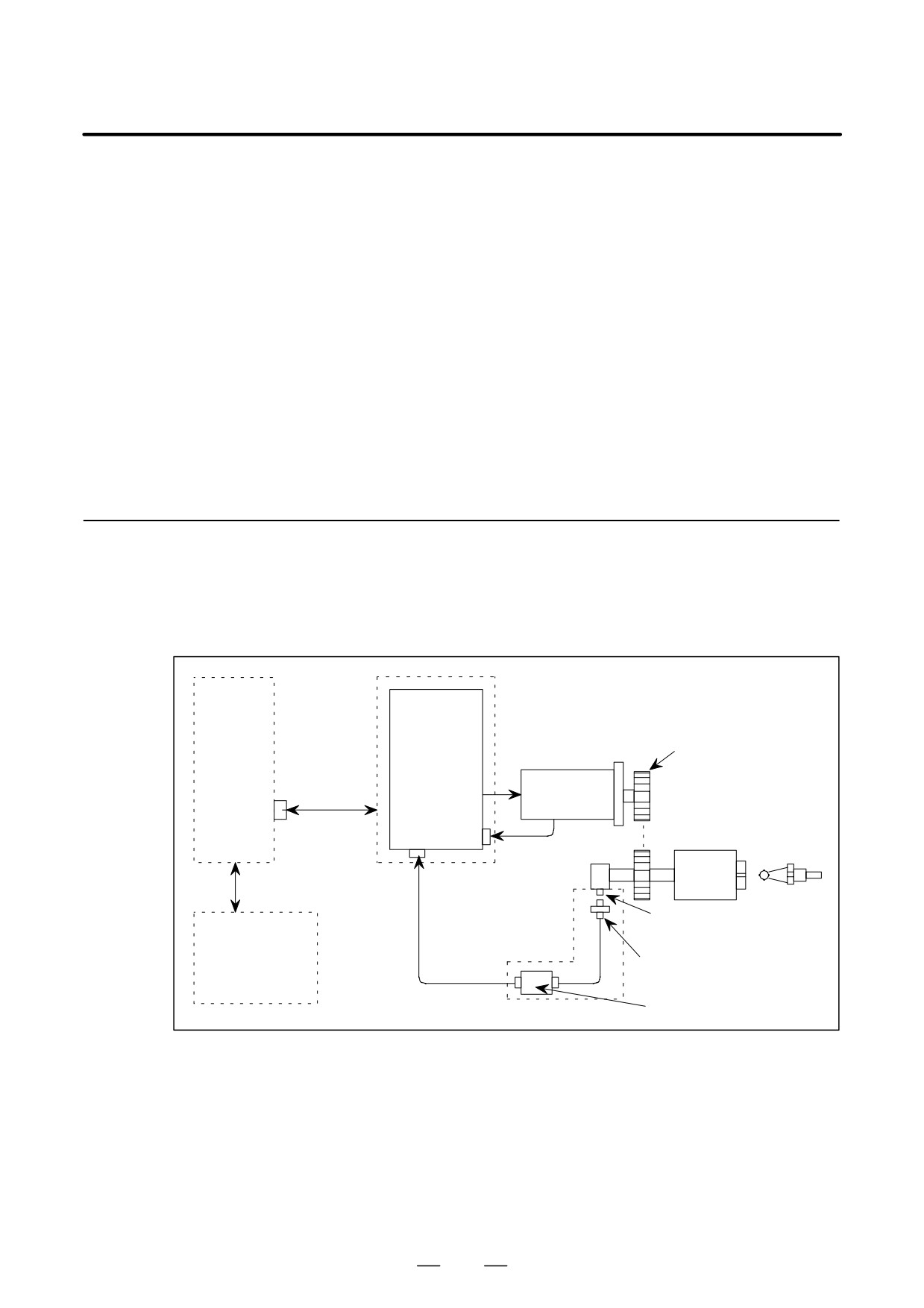
Configuration and
Order Drawing Number
Configuration
Spindle
amplifier
(SPM)
Gear or belt
CNC
CN11A
Communica-
tion cable
Spindle motor
JY2
Spindle
JY3
Speed feedback
Tool Å
Å
Å
Position feedback
Magnetizing element
ÅÅ
(Directly connected)
Power magnetic
sequence control
Magnetic sensor
Magnetic sensor head
circuit
Amplifier
477
11. OPTION RELATED TO SPINDLE
B-65162E/03
11.1.5.4
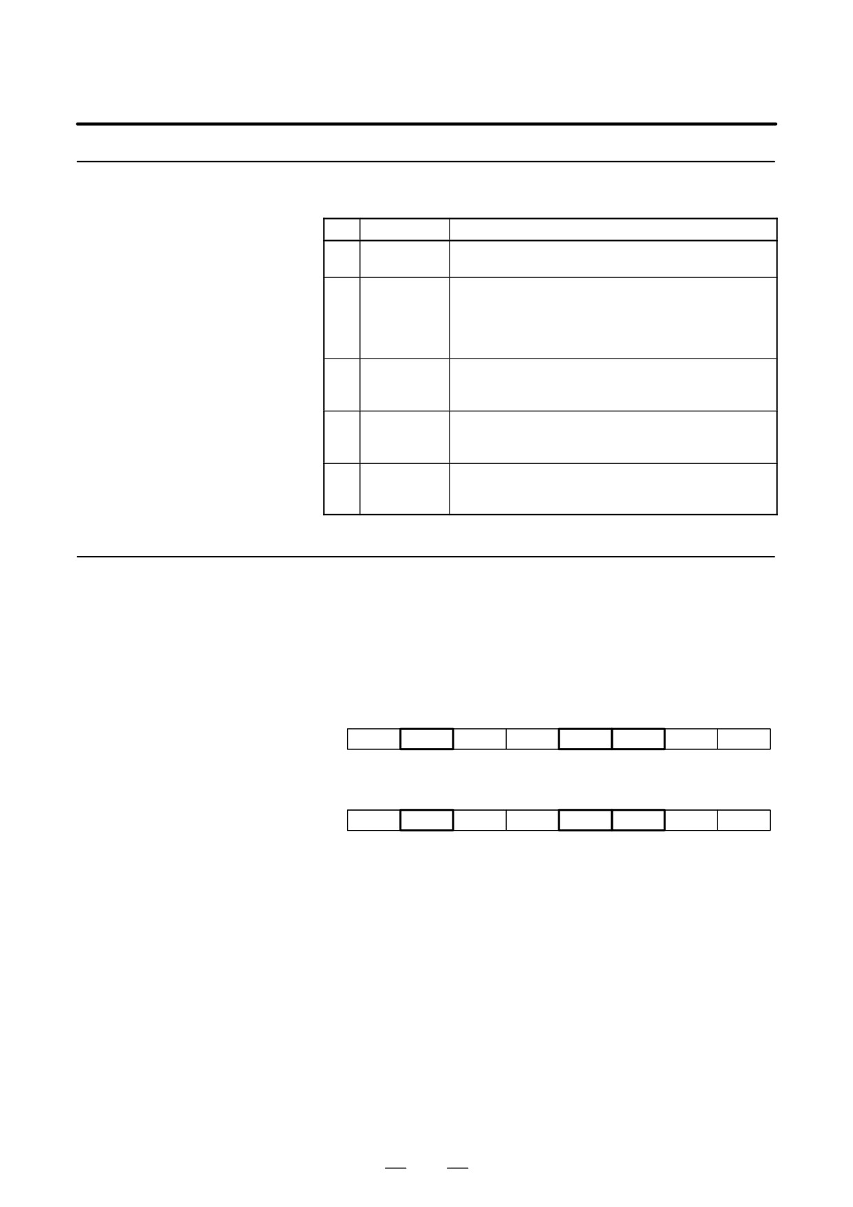
Specifications
No.
Item
Description
1
Magnetic
Refer to item 12.3.2.
sensor
2
Stop
Stops when the center of the sensor head faces the cen-
position
ter of the magnetizing element or the stop position check
scale of the magnetizing element.
The stop position can be adjusted to within "1° by the cir-
cuit.
3
Repeatability
"0.2° or less.
Excluding factors such as errors from the machine side,
for example, setting errors.
4
Max. hold
Continuous rated torque of the AC spindle motor.
torque at
orientation
5
Range where
Orientation stop position "240°
spindle can
be orientated
11.1.5.5
Signal Explanation
(1)
DI SIGNALS (PMC to CNC)
(a)
Spindle control signals
First spindle control input signal
FS0
FS15
FS16
#7
#6
#5
#4
#3
#2
#1
#0
: G229
G227
G070
MRDYA
ORCMA
SFRA
SRVA
CTH1A
CTH2A
TLMHA
TLMLA
Second spindle control input signal
FS0
FS15
FS16
#7
#6
#5
#4
#3
#2
#1
#0
: G223
G235
G074
MRDYB
ORCMB
SFRB
SRVB
CTH1B
CTH2B
TLMHB
TLMLB
(b)
Orientation (fixed position stop) command (ORCMA)
D This command signal is used to stop spindle movement at the preset
position to allow tool change and workpiece loading/unloading.
D When this signal is specified as ”1” while the spindle is rotating, the
rotation decelerates immediately and the spindle stops at the preset
position.
D When the orientation command is issued, set the spindle
forward/reverse rotation command (SFRA, SRVA) to ”0” for safety.
By means of this, the spindle will not start to rotate even in the unlikely
event ORCMA becomes ”0” during tool change.
D Set this signal to
”0” by the tool change completion signal or
workpiece loading/unloading completion signal.
D Always set the orientation command signal to ”0” when turning on
power.
478
B-65162E/03
11. OPTION RELATED TO SPINDLE
D When an emergency stop occurs during orientation, the orientation
command signal must be reset (”0”).
Return the ATC arm to the safe position so that it will not be damaged
if the spindle or tool rotates when the power is turned on.
(c)
Clutch/gear signals (CTH1A, CTH2A)
D
When there are two or more speed change gear stages between the
spindle and spindle motor, these signals are used to select a spindle
control parameter (position gain, gear ratio, velocity loop gain).
D
Depending on the clutch or gear state, make settings according to the
table below. Names such as HIGH GEAR are assigned only for
convenience. Arbitrary names may be assigned to the actual gears.
CTH1A CTH2A
0
0
: HIGH GEAR
0
1
: MEDIUM HIGH GEAR
1
0
: MEDIUM LOW GEAR
1
1
: LOW GEAR
(2)
DO Signals (CNC to PMC)
(a)
Spindle control signals
First spindle control output signal
FS0
FS15
FS16
#7
#6
#5
#4
#3
#2
#1
#0
: F281
F229
F405
ORARA
TLMA
LDT2A
LDT1A
SARA
SDTA
SSTA
ALMA
Second spindle control output signals
FS0
FS15
FS16
#7
#6
#5
#4
#3
#2
#1
#0
: F285
F245
F049
ORARB
TLMB
LDT2B
LDT1B
SARB
SDTB
SSTB
ALMB
(b)
Orientation (fixed position stop) completion signal (ORARA)
D When the orientation command is input and the spindle has stopped
near the preset fixed position (for example, within "1°), it becomes
”1”.
Condition for ORARA to become ”1”
Near to fixed position is set to the parameter.
If the above 3 conditions are satisfied, the orientation complete signal
is output.
If the orientation completion signal is not issued within a set period of
time after the orientation command signal is input, it is considered to
be abnormal. So it should be detected by the power magnetic sequence
and an orientation alarm should be issued.
Set the condition for judging that the spindle is near the fixed position
in the parameter used to specify the detection level for orientation
completion.
D Tool change or workpiece loading /unloading operations can be started
when this signal is ”1”.
479
11. OPTION RELATED TO SPINDLE
B-65162E/03
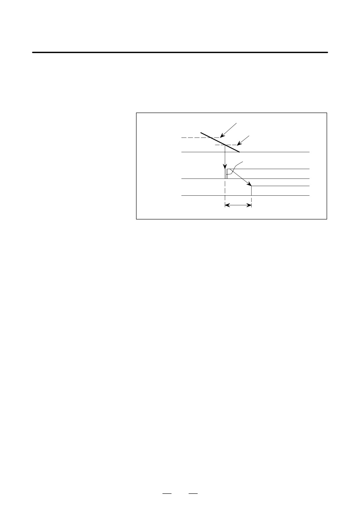
D
The spindle orientation completion signal is issued when the spindle
is within "1° of the preset position and so it does not always indicate
that the spindle has stopped completely. Some machines allow a very
short operation time for the ATC arm to grip the tool. In this case, start
the ATC arm operation after a short time (0.1 to 0.5 sec.) so that the
arm will grip the tool when the spindle has stopped completely.
Zero-speed detection level
Within "1° of the stop
Spindle
position
speed
Chattering
Orientation
completion
sequence
ORARA
ATC arm
operation
start signal
0.1 to 0.5 sec
D
This signal will become ”0” during a tool change if the spindle is
pushed away from the preset position by external force.
In this case, design a power magnetic sequence so that the tool change
operation is interrupted.
However, do not release the orientation command, and if the
orientation completion signal is issued again, perform a tool change.
D
If the automatic tool change (ATC) structure is such that it may cause
serious damage if a malfunction occurs, install a proximity switch to
generate a verification signal when the ATC enters an area in which the
automatic tool change operation can be performed. In addition to this,
perform a double safety check by the power magnetic sequence and
carry out a tool change.
480
B-65162E/03
11. OPTION RELATED TO SPINDLE
11.1.5.6
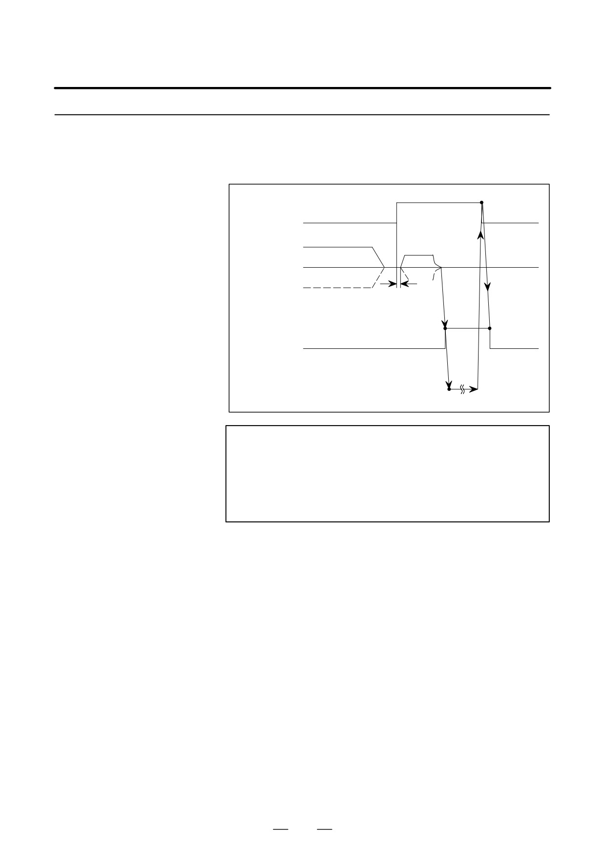
Sequences
(1) Orientation Command while Stopping
1
Orientation command
0
0
ORCMA
Stop
CW direction
Stop
Motor speed
CCW direction
Note
15 to 20 ms
1
Orientation completion signal
0
0
ORARA
ATC operation
Start
Completion
ATC operation
NOTE
The spindle motor rotation direction can be changed by
setting. In standard setting, the spindle motor will stop at
the fixed position in the direction the spindle motor was
rotating before this orientation command signal was
generated.
481
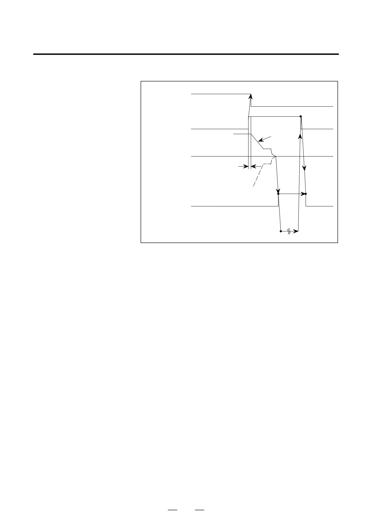
11. OPTION RELATED TO SPINDLE
B-65162E/03
(2)
Orientation Command During High-speed Rotation
Rotation command
1
SFRA, SRVA
(Configuration at
external sequence)
0
1
Orientation command
0
0
ORCMA
Deceleration
High-speed
CW direction
Motor speed
15 to 20 ms
CCW direction
1
Orientation completion signal
0
0
ORARA
ATC operation
Start
Completion
ATC operation
482