FANUC SERVO AMPLIFIER a series. DESCRIPTIONS (B-65162E/03) - page 14
B-65162E/03
10. INTERFACE SIGNALS
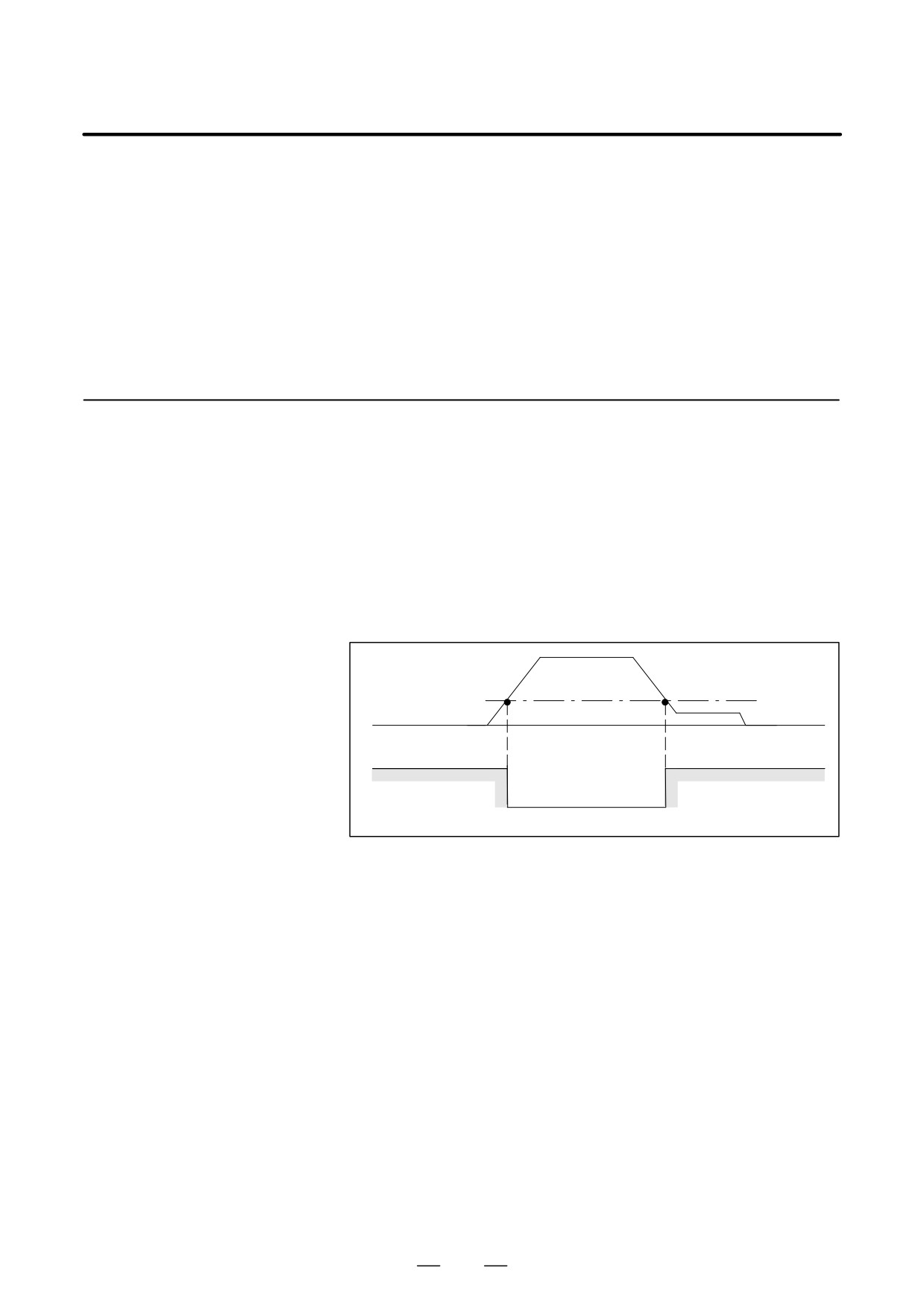
D The zero-speed detection point is 0.75% of the maximum speed
(standard initial setting for the parameter).
In other words, the zero-speed detection signal becomes SSTA = 1
when the rotation speed is 45 min-1 case of the maximum speed 6000
min-1.
D This signal is output when the above condition is satisfied, irrespective
of rotation commands (SFR, SRV).
D The minimum pulse width value of this signal is about 40 ms.
10.2.11
Speed Detecting Signal D SDTA = 1 occurs when the motor speed is lower than the speed which
(SDTA)
is set by parameter.
D This signal is used to detect that the rotation speed has become lower
than a certain speed set such as clutch selectable speed or gear
selectable speed.
D The speed detecting level can be set by parameter.
It is usually set 3% of the maximum speed in the case of gear change
or 30% of the maximum speed in the case of clutch change.
Motor
Speed detection level
speed
SDTA
1
0
1
Fig.10.2.11 (a) Speed Detection Signal
D For this signal, SDTA = 1 occurs when the absolute value of the motor
speed is reduced to be lower than the preset detection level,
irrespective of rotation commands (SFR, SV).
Reference
D Sequence of the gear
The gear shift in the CNC machine tool is one of the sequence controls.
shift
The electric circuit signal in the sequence is used to move the spindle gear,
which is an important component of the machine. It is then necessary to
check that the spindle motor revolution is in low speed to switch the gear
safely.
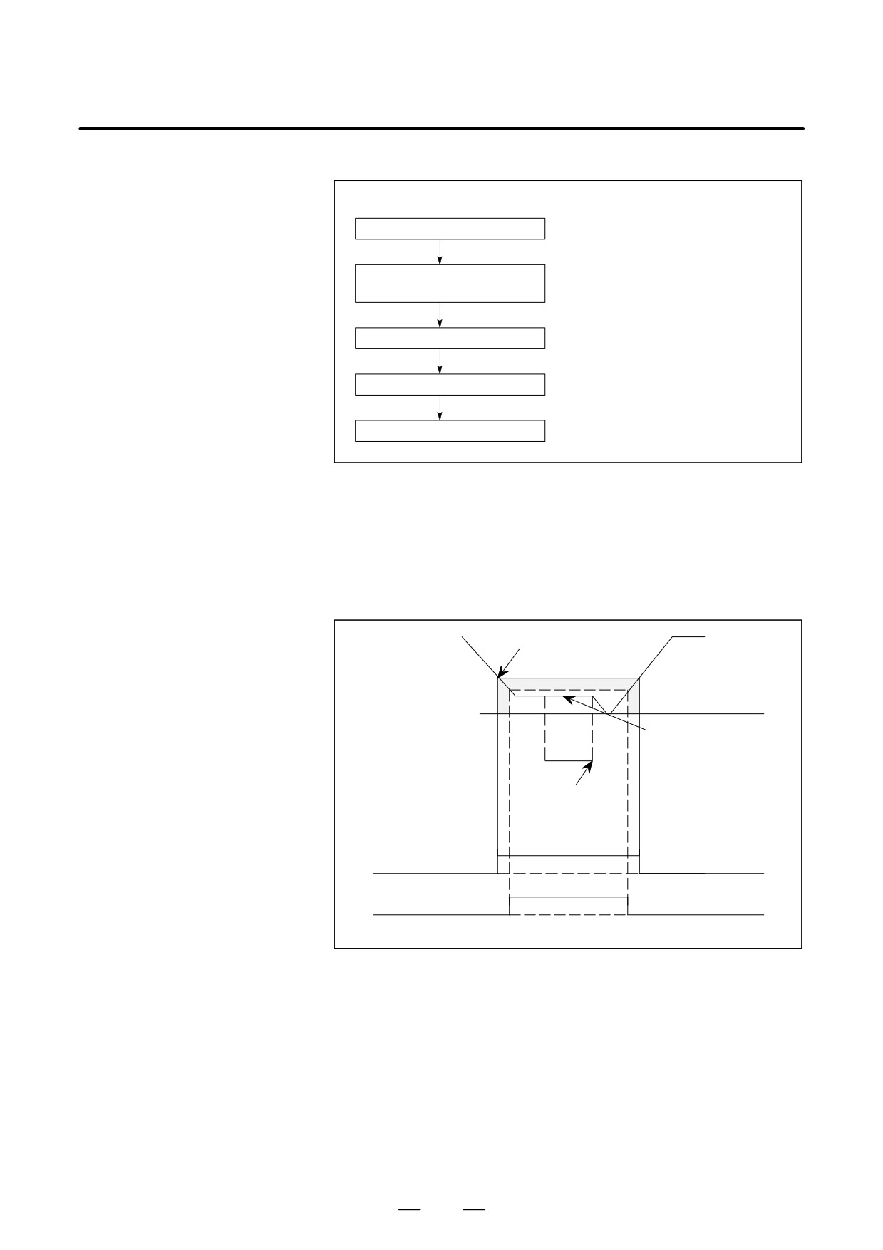
The following is an example of sequence at gear shift, when the speed
detection signal (gear selectable signal) was used. This example can be
referred to when designing the magnetics sequencer.
393
10. INTERFACE SIGNALS
B-65162E/03
D An example of gear shift sequence using speed detection signal
(Sequence)
(Check signal)
Gear shift command
Low speed revolution com-
mand of the spindle motor
Speed check
Speed detection signal 1
Shifter moves
(or zero-speed signal 1)
End of gear shift
To change the gear safely, it must be checked that the spindle motor
revolution is low enough before moving the shifter. If the zero-speed
signal is also applied, the safety can be doubly checked.
Essential reason
If the shifter moves when the spindle motor is rotating at high speed, the
gear will break.
Gear selectable
motor speed range
Spindle motor speed
0 min-1
Spindle motor
speed at gear shift
(Low speed)
Shifter moves
End of
gear shift
1
0
0
Speed detection signal
(gear selectable signal)
Zero-speed detect signal
Fig.10.2.11 (b) Speed Detection Signal
394
B-65162E/03
10. INTERFACE SIGNALS
10.2.12
Speed Arrival Signal
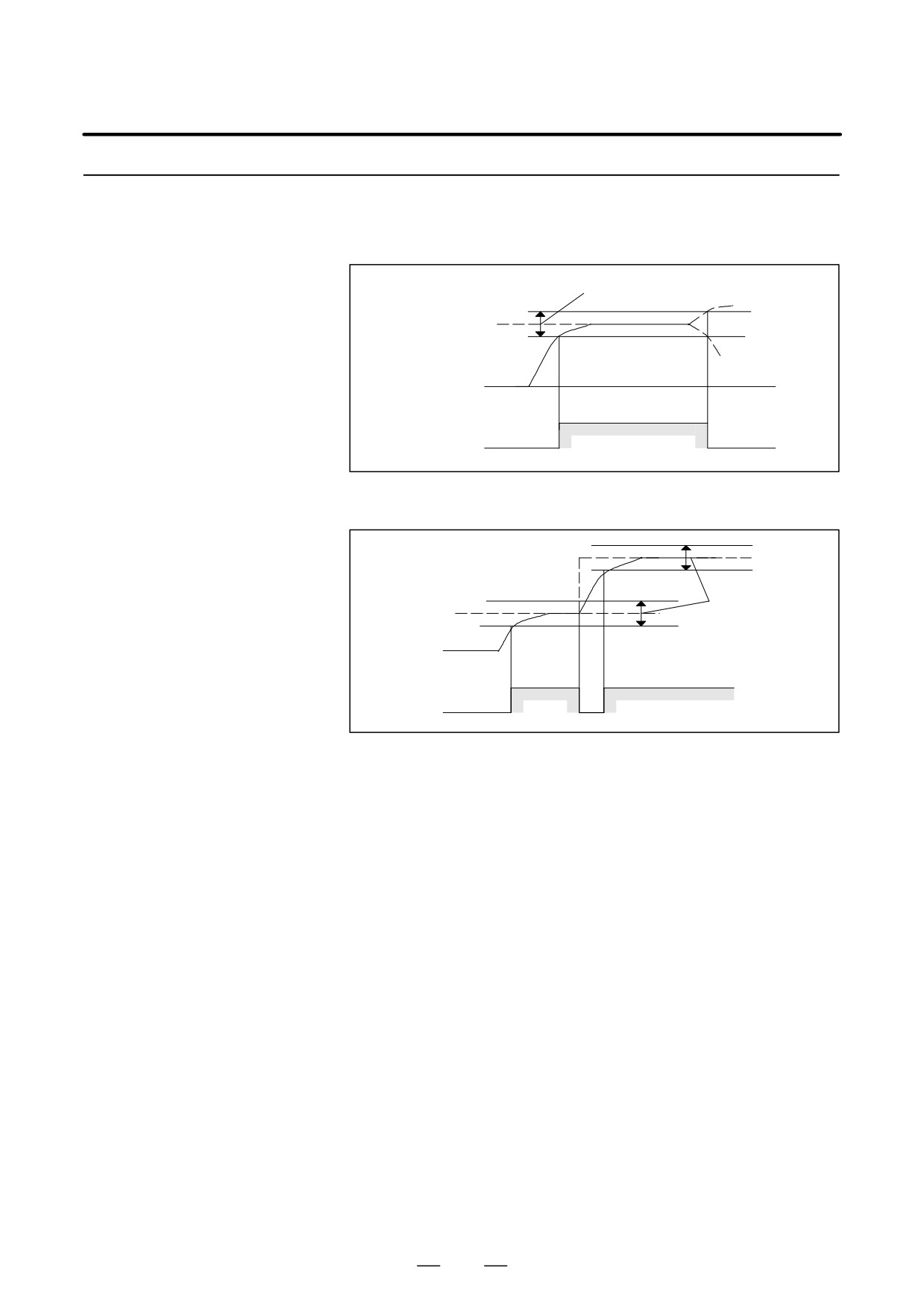
D SARA = 1 occurs when the actual rotation speed of the spindle motor
arrives within the range set by the speed command.
(SARA)
Detection range
Command
speed
Motor speed
0
1
0
SARA
Fig.10.2.12 (a) Speed Arrival Signal 1
Command
speed (2)
Command
speed (1)
Detection range
Motor
speed
0
1
0
1
SARA
Fig.10.2.12 (b) Speed Arrival Signal 2
D The setting range is "1 to 100% of the command speed. However,
when the speed is less than 10% of the maximum rotation speed, the
detection range becomes wider than the preset range.
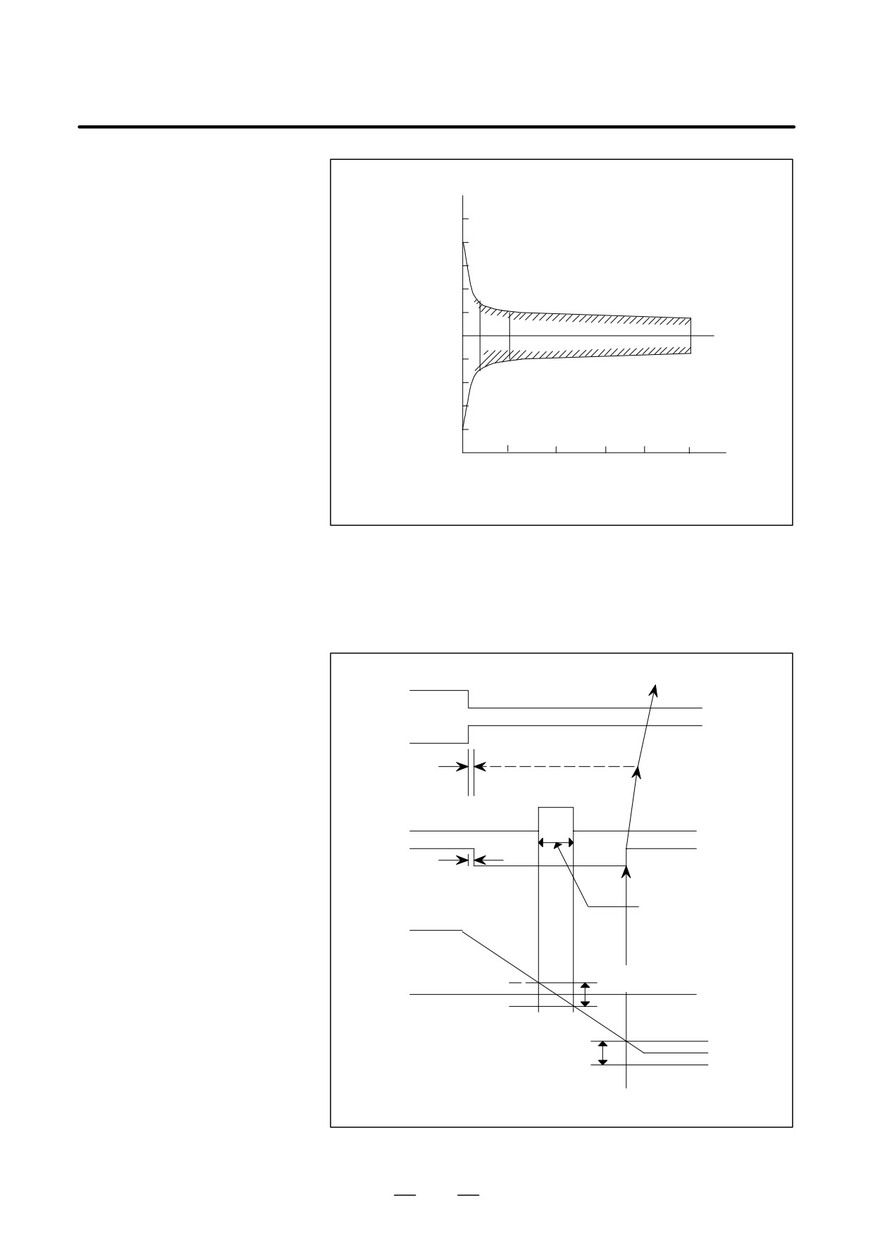
D The standard setting at shipment is "15%. However, the detection
range of this speed arrival signal at low speed widens as shown in the
diagram below.
395
10. INTERFACE SIGNALS
B-65162E/03
Detection range of speed
arrival signal [%]
200
180
177% (at 80 min-1)
160
140
120
115%
100
80
85%
60
40
23% (at 80 min-1)
20
0
MAX Speed
Speed command
Rotation speed (min-1)
Fig.10.2.12 (c) Detection Range of the Speed-Arrival Signal
D
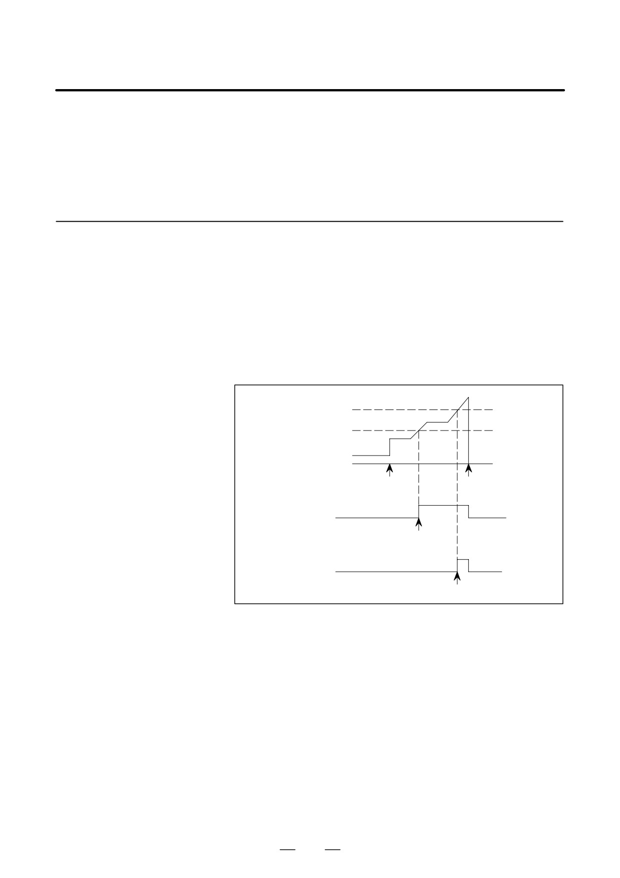
If one of these signals, SFRA or SRVA, is not 1, it is not outputted.
D
It is possible to control the back rotation of the tapping cycle in the
following manner by using this signal.
SFRA(forward rotation
FIN
command)
0
1
SRVA(back rotation command)
0
1
40 ms
1
SSTA (zero-
About
0
speed detection)
SARA(speed arrival)
40ms
ON
γ1
γ1=40 ms
OFF
Minimum value of
pulse width
Forward rotation
Motor speed
Zero-speed
0
detection range
Back speed
Speed arrival
detection range
Note) The time γ1 is delayed until the SARA signal becomes 0.
Fig.10.2.12 (d) Timing Chart of the Speed-reached Signal
396
B-65162E/03
10. INTERFACE SIGNALS
If the back rotation command is transmitted, the spindle motor starts
deceleration and, because the arrival signal becomes 0 at under 40 ms,
it next detects the speed arrival signal has again become 1 via speed
zero and sets the end of the back command.
D This signal is used as the confirmation signal (FIN signal) for the
forward rotation (M03) and back rotation (M04) commands.
10.2.13
Load Detection Signal
D Assume that the maximum output (10 V) of the load meter (LM) is
100%. When the output of the load meter reaches the parameter
(LDT1A, LDT2A)
settings (%), load detection signal is set to 1.
D Parameter settings for these signals are set independently.
D Using these signals, the PMC reduces the feedrate or stops the feed to
prevent the spindle from stopping when cutting overload is applied to
the spindle.
D The following example shows the case in which the spindle is
controlled with two load-detection levels set.
LDT2A threshold level
LDT1A threshold level
Output of the load meter
0V
Cutting
The spindle stops.
starts.
LDT1A
Feedrate is reduced here.
LDT2A
The feed motor stops here.
D When using only one load-detection level to stop the feed motor,
perform spindle control according to the specifications.
D After the speed command is changed, this signal is not output until 10
seconds elapse. (The delay is specified by parameter. (For FS-16, this
parameter is 4082))
397
10. INTERFACE SIGNALS
B-65162E/03
10.2.14
Soft Start Stop Cancel
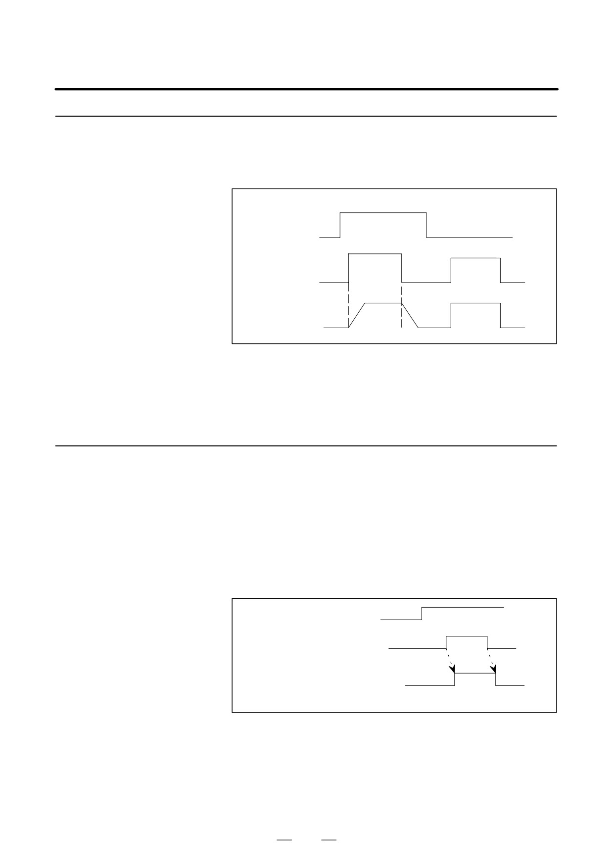
D In the state that the soft start/stop cancel signal is 1, the soft start/stop
function is enabled and the gradient of the speed command changing
Signal (SOCAN)
at acceleration/deceleration can be set in the following manner.
Soft start/stop cancel signal
1
0
0
External speed
command
Spindle amplifier
internal speed
command
D If the emergency stop signal input is set to *ESPA=0, the soft start/stop
function is automatically disabled.
D The change in the speed to be specified is set by parameters.
(For
FS-16, this parameter is 4030.)
Setting parameter is 0, the soft start/stop function is disable.
10.2.15
Signal For Controlling
D
When the position of the spindle is being controlled in a mode such
as spindle orientation control, spindle index control, or Cs contouring
Velocity Integration
control mode, the spindle may be clamped with a brake.
(INTGA)
If the spindle is kept clamped with a small positional deviation, the
integration control for the velocity attempts to correct the deviation to
zero, resulting in excessive flow of current into the motor.
Disabling the integration control for the velocity by setting this signal
prevents excessive current from flowing into the motor when a small
positional deviation exists.
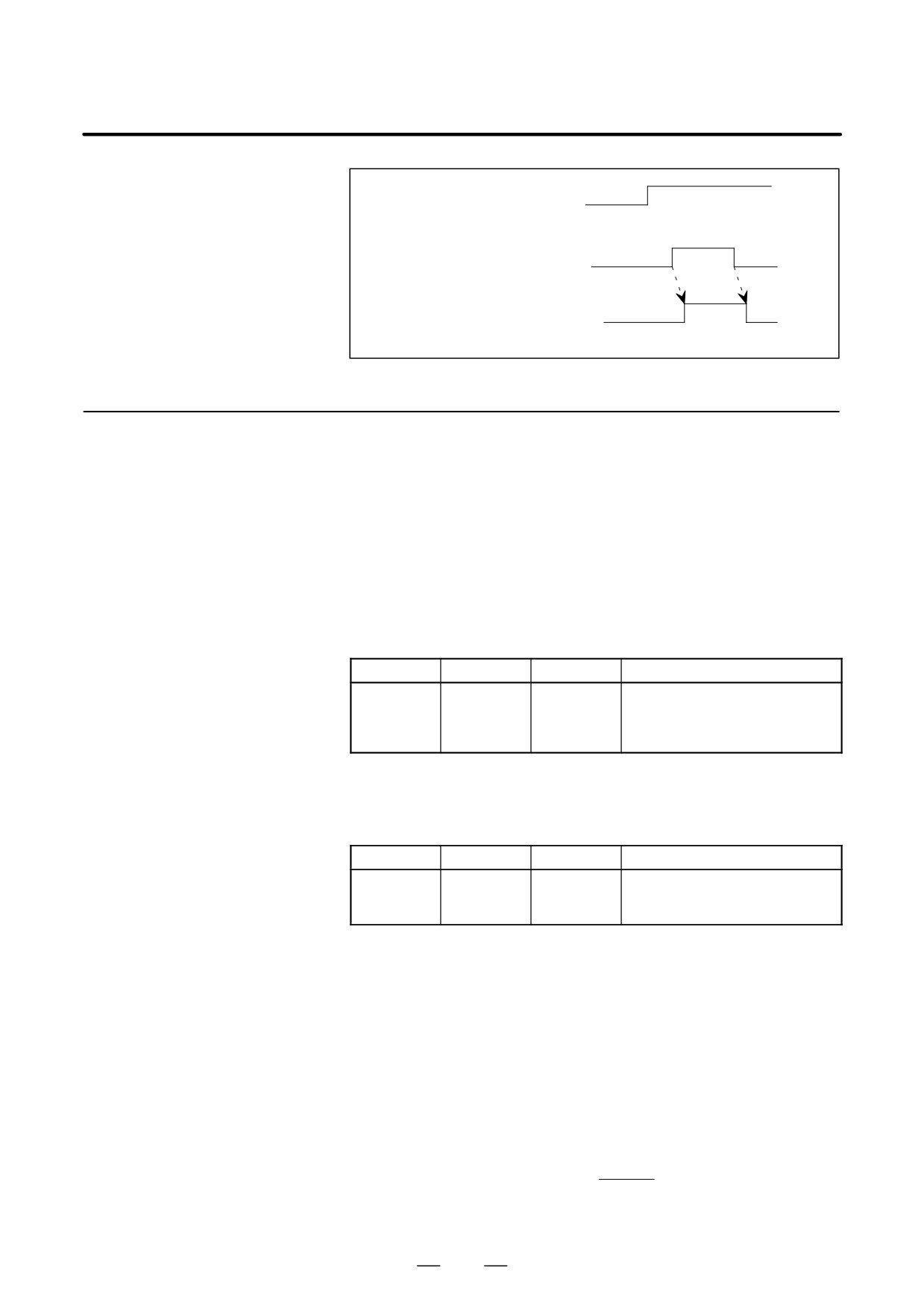
Position control signal for the
spindle
Spindle clamping signal
Signal for controlling velocity
integration
INTGA
D
When two spindles hold a workpiece in the spindle synchronization
control mode with a small synchronous error, the integration control
for the velocity attempts to correct the error to zero, resulting in
excessive flow of current into the motor.
Disabling the integration control for the velocity by setting this signal
prevents excessive current from flowing into the motor when a small
synchronous error exists.
398
B-65162E/03
10. INTERFACE SIGNALS
Spindle synchronization
control signal
Two spindles hold a
workpiece.
Two spindles hold a
Chuck
workpiece. (Chuck closed)
closed
Signal for controlling velocity
integration
INTGA
10.2.16
Spindle Override
D
In the normal speed control mode (including when the soft start/stop
function is used), this function overrides speed, with analog voltage
Command (Function)
input from an external unit to the spindle amplifier.
With Analog Input
D
The override function with analog input voltage is enabled when this
Voltage (OVRA)
signal is set to 1 in the normal speed control mode (including when the
soft start/stop function is used).
D
A limit (100% or 120%) of this function should be assigned to the
following parameters:
FS0
FS15
FS16
Contents of parameter
6506#5
3006#5
4006#5
Setting of input range of spindle
analog override:
0 : 0 to 100%
1 : 0 to 120%
The maximum analog input voltage is +4.5 V. If an override speed
exceeds the maximum speed, it is clamped by the maximum speed.
D
An override type is specified using the following parameter.
FS0
FS15
FS16
Contents of parameter
6506#6
3009#5
4009#6
Override type setting
0 : Linear function type
1 : Quadratic function type
Linear function type override
An actual override value corresponds to the entered override
value on a one-to-one basis.
OVROUT = OVRIN
Quadratic function type override
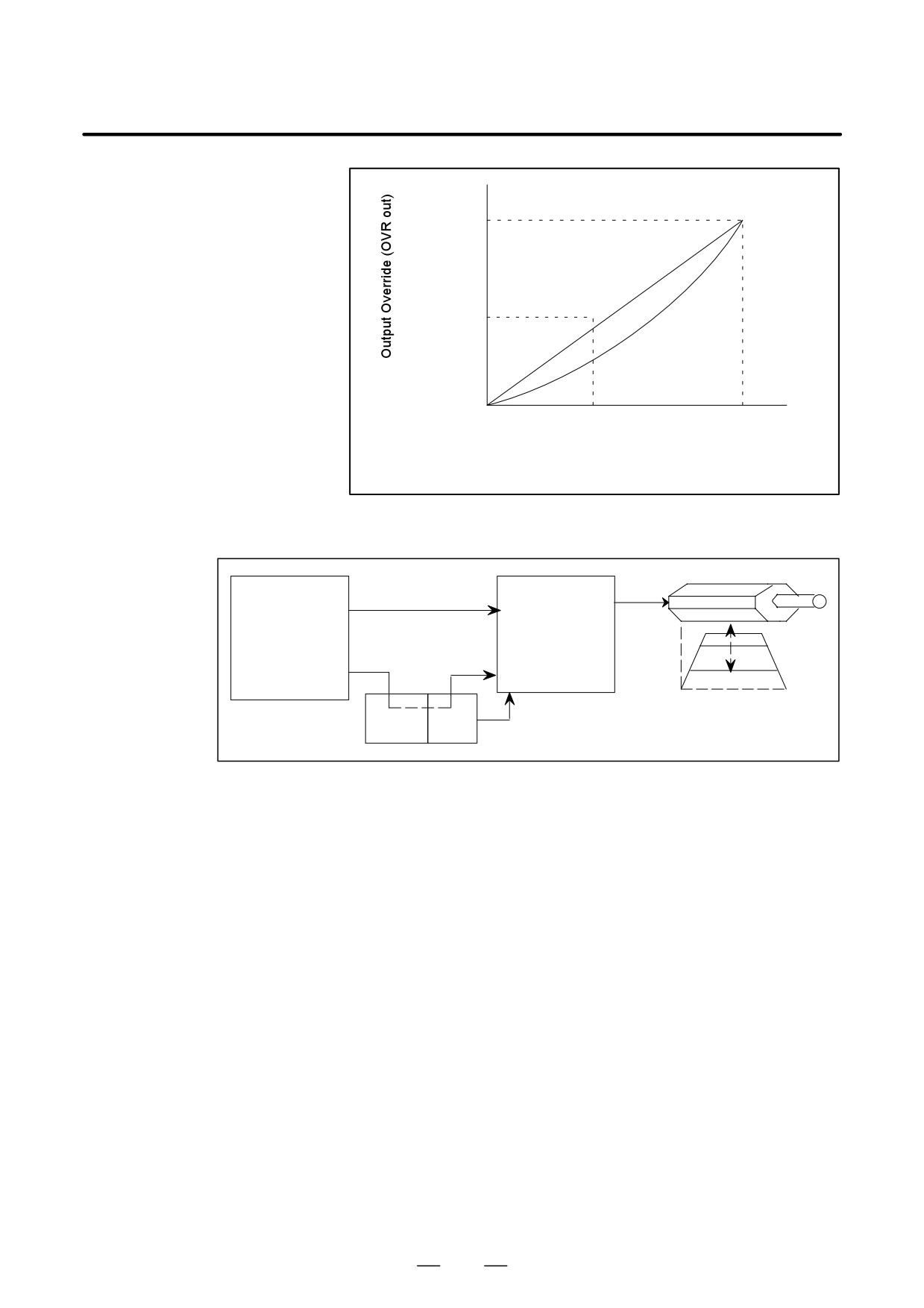
An actual override value corresponds to the entered override
value on the quadratic function basis. The speed resolution of
quadratic function type override is low in a high speed range and
high in a low speed range, as compared with that of linear
function type override.
2
OVRIN
OVROUT + OVRMAX ǒ
Ǔ
OVRMAX
OVRMAX : Max of override
399
10. INTERFACE SIGNALS
B-65162E/03
[%]
100 (120)
50 (60)
0
0
50
100
[%]
(60)
(120)
Input Override (OVR IN)
D The following figure shows a system configuration in terms of this
function.
Analog input voltage
for override
Machine
Spindle
operator’s
amplifier
Signal for enabling/
panel
disabling override
Speed
Override
Value specified by a speed command
PMC
NC
Ladder
Fig.10.2.16 (a) System Configuration
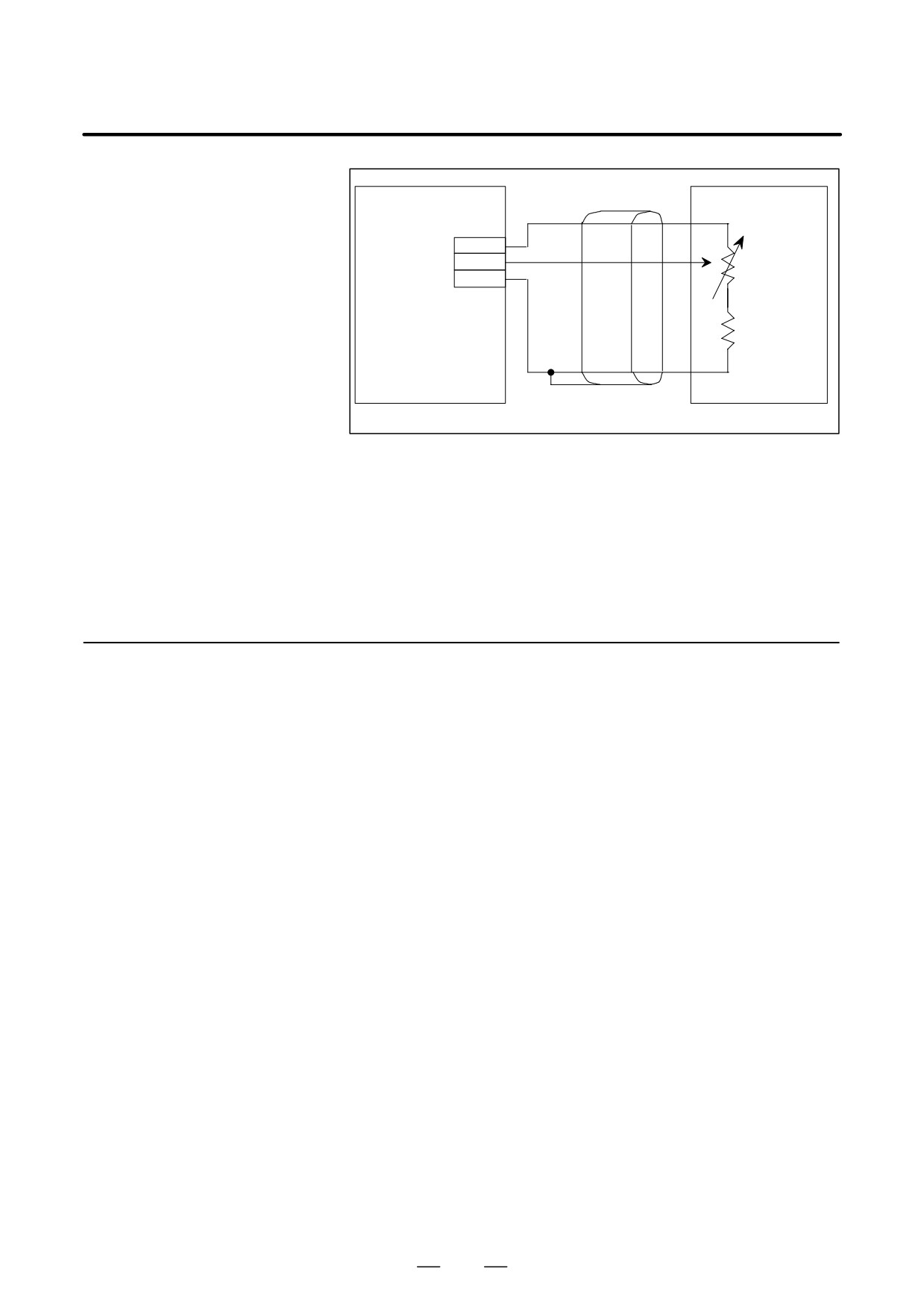
D The following figure shows the connection of units when analog
voltage is input.
The limit (Override 100 or 120%) for voltage input into the OVR2
terminal is 4.5 V.
Override can be set in increments of 1%.
Total resistance of resistors VR and R1 must be 1 kΩ to 10 kΩ.
The following values are examples for the conventional analog
spindle:
VR = 1.0 kΩ, R1 = 1.0 kΩ or 2.4 kΩ
400
B-65162E/03
10. INTERFACE SIGNALS
JY1
Reference
voltage
1
0VR1
2
Analog input
0VR2
Variable
20
0V
0V
resistor VR
Resistor R1
Reference voltage
output: 4.75 "0.25 V
Shielded
(Machine operator’s panel)
(Spindle amplifier module)
wire
Fig.10.2.16 (b) Connection between a Spindle Amplifier and
Machine Operator’s Panel
D When the signal for enabling/disabling this override function is set, or
the parameter for an override limit is changed, the speed of the motor
may change substantially. Stop the motor first, and then set the signal
or change the parameter.
10.2.17
Motor Power Off Signal
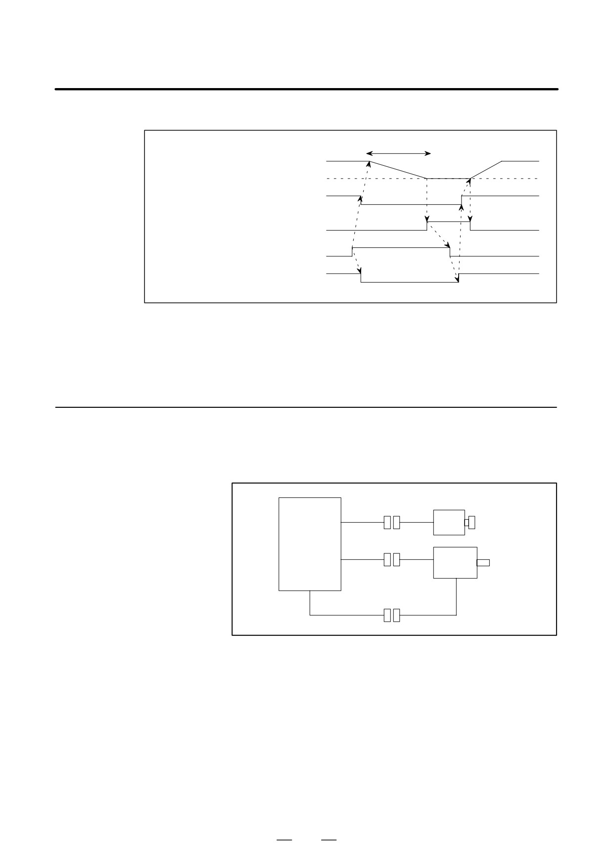
D This signal is used to cut the power of the motor when a failure occurs
while the spindle synchronization control or the gear cutting machine
(MPOFA)
is operating. When the power is cut, the motor runs free.
D This signal only cuts the power of the motor.
D The power can be restored to the motor again after the motor stops
(zero speed signal, SSTA = 1).
If the signal is canceled, the power cannot be restored to the motor
while the motor is operating (SSTA = 0).
D After the power of the motor is cut, all the operation modes(*1) must
be canceled for safety.
After the motor stops (SSTA = 1), set the operation modes again.
When the power is cut during position control, an alarm such as
excessive deviation may occur because position control remains
effective.
(*1) Example of operation modes:
- Forward rotation command (SFRA)
- Reverse rotation command (SRVA)
- Spindle orientation (ORCMA)
- Rigid tapping (RGPT, RGTAP)
- Spindle synchronization control (SPSYC, SPPHS)
- Cs-axis control
- Cs contouring control (COFF, CON, SCNTR1, SCNTR2, etc.)
- Differential mode (DEFMDA)
401
10. INTERFACE SIGNALS
B-65162E/03
D Example of the sequence
Free run
Motor speed
0 min-1
ON
Motor power
OFF
1
Zero speed detection signal, SSTA
0
1
Motor power off signal, MPOFA
0
ON
Operation mode such as SFRA
OFF
D Setting bit 2 of parameter 4069 (FS16) to 1 cuts off the power of the
motor as soon as the AL-24 spindle alarm (serially transmitted data
error) occurs. The motor usually decelerates and stops when the alarm
occurs.
10.2.18
Disconnection
(1) This signal is used when it is necessary to disconnect a spindle
Annulment Signal
amplifier from a spindle motor temporarily.
(DSCNA)
Position coder
Feedback
signal
JY4
SPM
Feedback
signal
JY2
Motor
Power line
(2) Using this signal enables preventing a motor overheat or feedback
signal disconnection alarm condition when the feedback signal is
disconnected.
(3) Before the power line is disconnected, the motor excitation off
affirmation (EXOFA) signal can be used to check that the motor is not
energized.
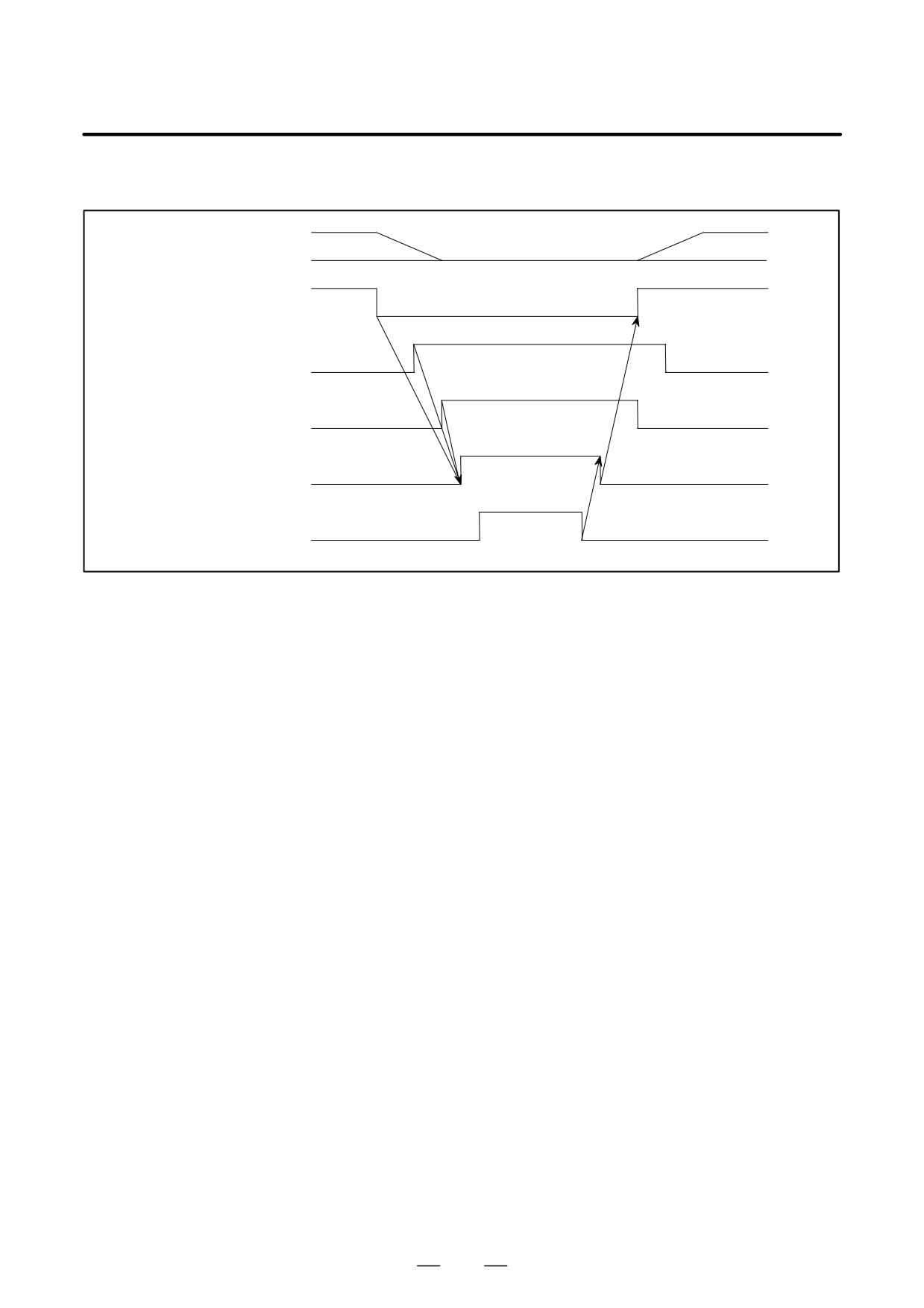
(4) Before disconnecting the feedback signal and power line, set all of the
SFRA, SRVA, ORCMA, MRDYA, and *ESPA commands to 0, and
check that the EXOFA signal is 1, then set this signal to 1. After
reconnection is completed, reset the signal to 0.
402
B-65162E/03
10. INTERFACE SIGNALS
(5) Sequence example
Motor speed
0 min-1
SFRA,SRVA,ORCMA,
1
MRDYA,*ESPA
0
1
SSTA
0
1
EXOFA
0
1
DSCNA
0
Disconnection
Connection/
During
Connection
disconnection
disconnection
403
10. INTERFACE SIGNALS
B-65162E/03
10.3
SPINDLE AMPLIFIER
OUTPUT SIGNALS
(α SERIES SPINDLES)
10.3.1
Speed Meter
D
The rotation speed of the AC spindle motor can be indicated by
externally connecting a speedmeter.
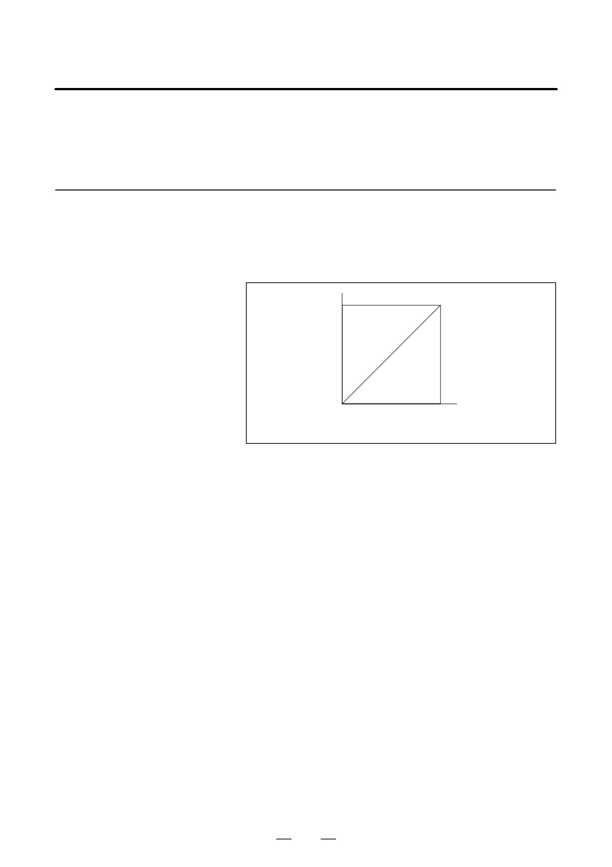
Voltage Signal
A voltage
(DC) proportional to the rotation speed is output,
(SM)
irrespective of the forward or reverse rotation of the motor. A +10V
is output at the maximum revolution.
+10V
Output
voltage
(DC)
0V
0
(Forward rotation /reverse rotatiopn)
Motor rotation speed
D
Use the following speedmeter
(DC voltmeter)
- One-sided deflection DC voltmeter
- DC voltage 10V full scale
- Internal resistance higher than 10 kΩ
Example)
DC voltmeter LM-80: Kuwano Electrical Manufacturing Co., Ltd.
404
B-65162E/03
10. INTERFACE SIGNALS
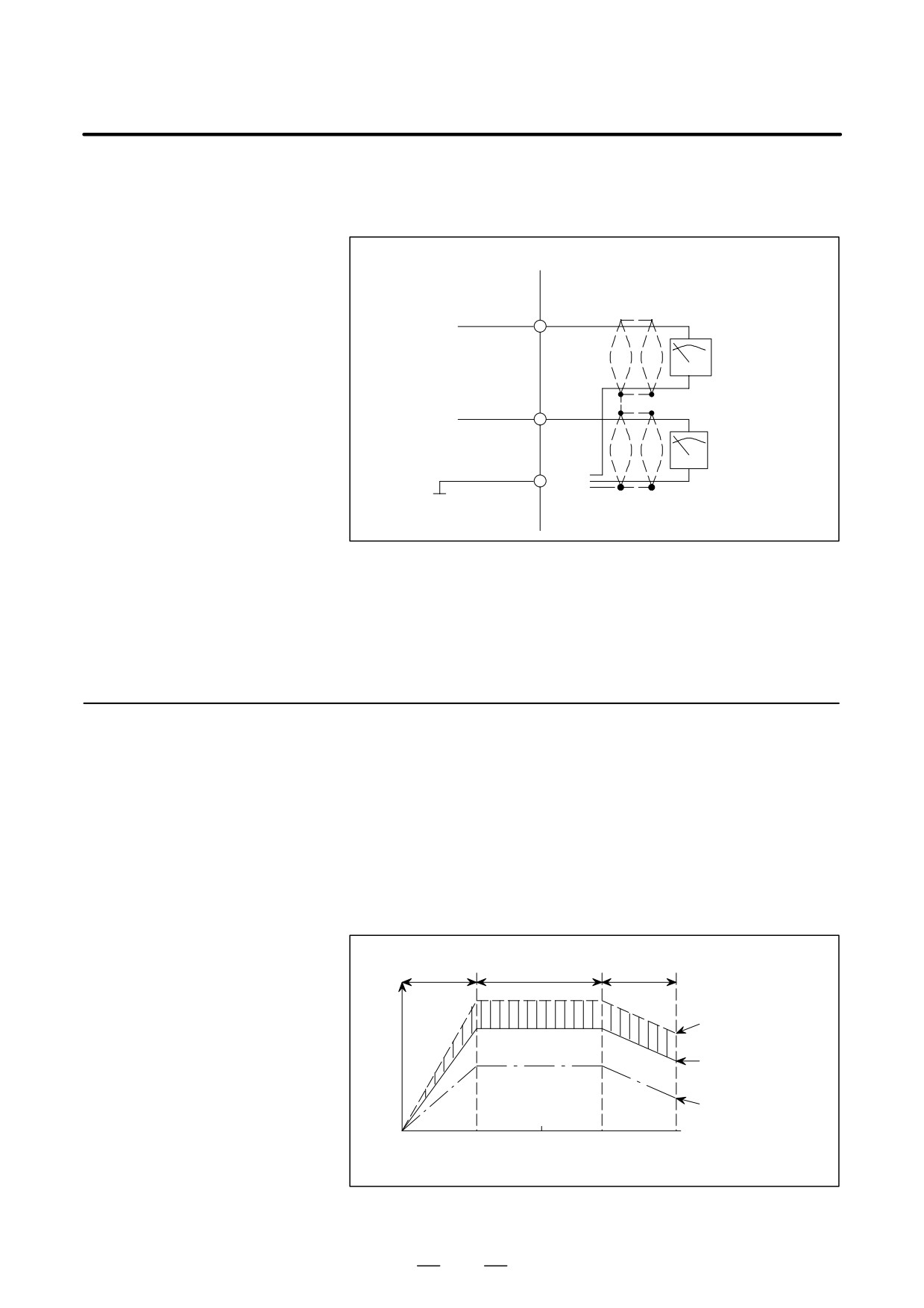
D With respect to the speed indication voltage, the forward
rotation/reverse rotation output voltage is calibrated by a parameter.
The voltage accuracy is max. "3%.
Spindle amplifier
SM (17)
+
Speed meter voltage
Speed meter
MIN]1
-
LM (16)
+
Load meter voltage
Loadmeter
%
(19)
-
0M
0V
Fig.10.3.1 Connecting the Spindle Servo Unit to a
Speedmeter and a Load Meter
D Use a 2-core shielded cable.
10.3.2
Load Meter Voltage
D The load meter indicates the load factor, which is the ratio of the load
to the maximum output obtainable by the spindle motor at the input
(LM)
voltage and working revolutions when the machine tool spindle is
rotating without load or when cutting is in progress.
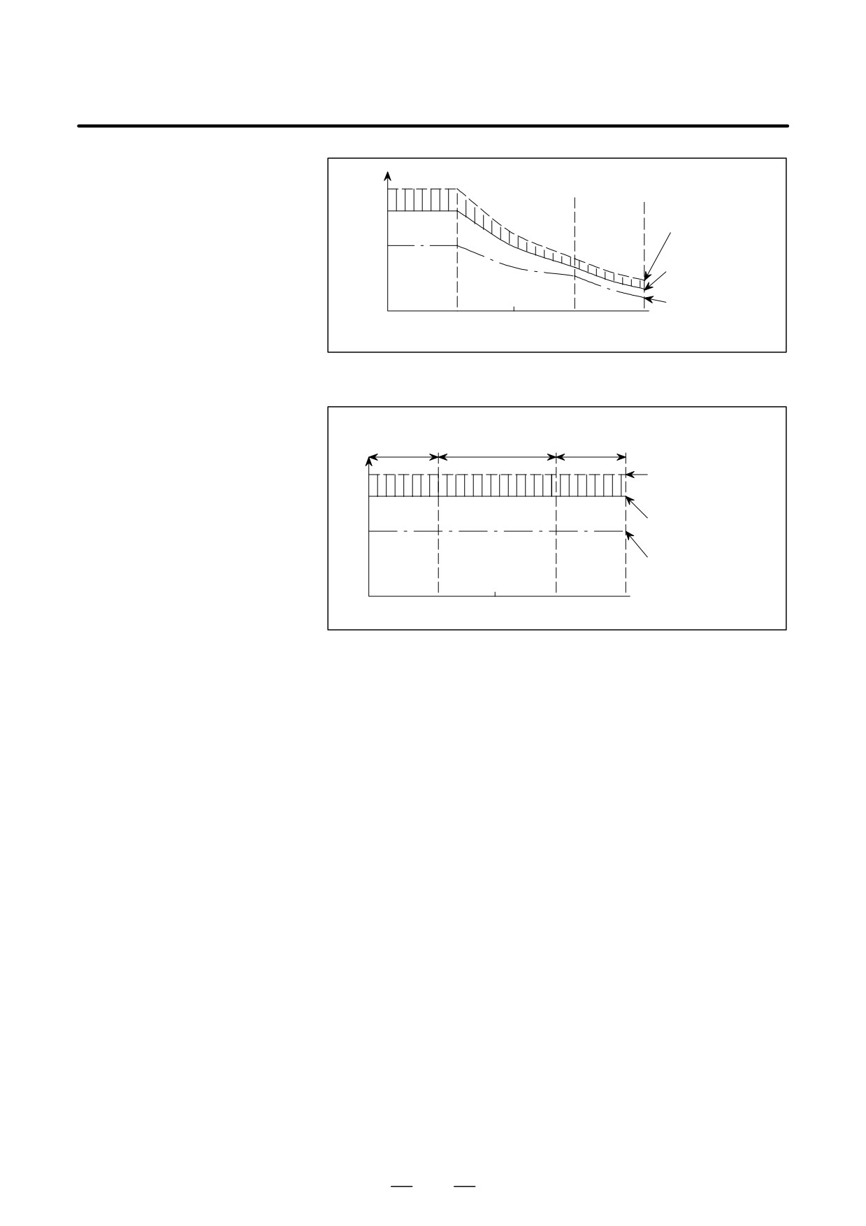
D When the rated input voltage is applied, the revolutions-to-spindle
motor output relation, revolutions-to-torque relation and
revolutions-to-indicating voltage relation are as shown in Figs. 10.3.2
(a), 10.3.2 (b), and 10.3.2 (c).
Constant
Constant output
Lowered output
torque region
power region
power region
Maximum output
P
power of motor
(]30min. rated
output power
120%)
Spindle
motor
30min. rated output
output
power
power
[kW]
Continuous rated
output power
0
(Base speed)
Maximum speed
(Maximum
of constant power
speed)
Motor speed
region
Fig.10.3.2 (a) Spindle Motor Output
405
10. INTERFACE SIGNALS
B-65162E/03
T
Maximum torque
of motor
(]30min. rated
Spindle
torque_120%)
motor
torque
30min. rated torque
[kg·m]
Continuous rated
0
torque
Motor
speed
Fig.10.3.2 (b) Spindle Motor Torque
Constant
Constant output
Lowered output
torque region power region
power region
Maximum output
power of motor
10V
(]30min. rated output
8.3V
power
120%)
30min. rated output
power
Continuous rated
output power
Motor speed
Fig.10.3.2 (c) Voltage Used for Operating a Load Meter
D
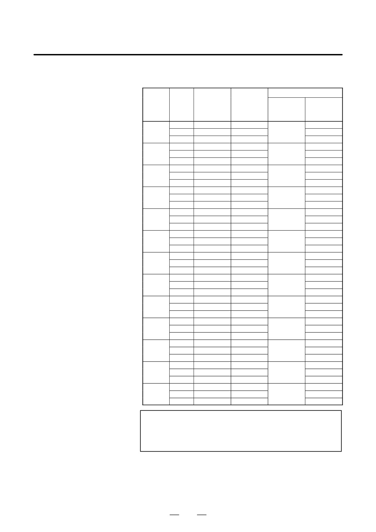
The relation between each spindle motor output and the indicating
voltage of the load meter is as shown in Table 10.3.2 (a), assuming
that the continuous rated output of the spindle motor is 100%.
D
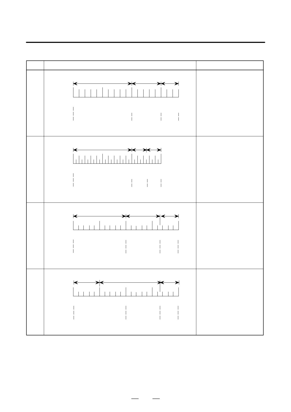
Four types of indications of the load meter may be considered
approximately from Table 10.3.2 (a). For the indication of the load
meter in this case, refer to examples shown in Table 10.3.2 (b).
D
Machine tool builders are requested to prepare a load meter (DC
voltmeter) which complies with the following specification.
- One-side deflecting DC voltmeter
- DC voltage 10V, full scale
- Internal resistance 10 kΩ
Example)
DC voltmeter LM-80 made by KUWANO DENKI
D
Use a 2-core shielded cable.
406
B-65162E/03
10. INTERFACE SIGNALS
Table.10.3.2 (a) Relation between each spindle motor output and
indicating voltage of load meter
Ratio
Example of load meter
Indicating
asuming that
Output
voltage of
Model
continuous
Type of
(kw)
load meter
Ratio to full
rated is 100%
applicable
(V) (Note)
scale (%)
(%)
load meter
0.55
4.2
100
100
α0.5
1.1
8.3
200
E
200
1.32
10.0
240
240
1.5
5.7
100
102.2
α1,
2.2
8.3
147
A
150
α1/15000
2.64
10.0
176
180
1.1
2.5
100
100
α1.5
3.7
8.4
338
D
338
4.4
10.0
400
400
2.2
5.0
100
101
α2,
3.7
8.4
166
C
166
α2/15000
4.4
10.0
200
200
3.7
5.6
100
100.8
α3,
5.5
8.3
148
A
150
α3/12000
6.6
10.0
178
180
5.5
6.1
100
109.8
α6,
7.5
8.3
136
A
150
α6/12000
9.0
10.0
164
180
7.5
5.7
100
102.6
α8,
11.0
8.3
146
A
150
α8/8000
13.2
10.0
175
180
11
6.1
100
109.8
α12,
15
8.3
136
A
150
α12/8000
18
10.0
164
180
15
6.7
100
100.5
α15,
18.5
8.3
124
B
125
α15/8000
22.2
10.0
149
150
18.5
7.0
100
105
α18,
22.0
8.3
118
B
125
α18/8000
26.4
10.0
142
150
22.0
7.0
100
105
α22,
26.0
8.3
118
B
125
α22/8000
26.0
10.0
142
150
30.0
6.7
100
105.0
α30,
37.0
8.3
124
B
125
α30/6000
44.4
10.0
149
150
37.0
6.8
100
103
α40
45.0
8.3
122
B
125
54.0
10.0
146
150
NOTE
Accuracy
of
the load
meter voltage
depends
upon the
speed used or the input voltage. The maximum deviation
is approximately ±15%.
407
10. INTERFACE SIGNALS
B-65162E/03
Table.10.3.2 (b) Examples of load meter type (1/2)
Type
Indication of load meter
Remarks
Motor Models
White Band
Yellow Band Red Band
Color
α1, α1/15000, α3, α3/12000, α6,
Division
α6/12000, α8, α8/8000, α12,
α12/8000, αP8, αP8/8000,
ÅÅÅ
αP12, αP12/8000, αP22,
Indica-
ÅÅÅ
αP22/8000, αP50, α6HV, α8HV,
tion
0
50
100
150
180
A
α12HV
%
Corres-
pon-
dence
to
0V
5.55V
8.3V
10.0V
voltage
Yellow
Red
Motor Models
Color
White Band
Band
Band
α15, α15/8000, α18, α18/8000,
Division
α22, α22/8000, α30, α30/6000,
α40, αP15, αP15/8000, αP18,
ÅÅÅ
αP18/8000, αP30, αP30/6000,
Indica-
0
50
100
125Å150
αP40, αP40/6000, α15HV,
B
tion
%
α18HV, α22HV, α30HV, α40HV,
Corres-
α60HV
pon-
dence
to
0V
6.66V
8.3V
10.0V
voltage
Motor Model α2, α2/15000
Red
Color
White Band
Yellow Band
Band
Division
ÅÅÅ
ÅÅÅ
Indica-
C
tion
0
50
100
150
166 Å200
Corres-
%
pon-
dence
0V
5.0V
8.3V
10.0V
to
voltage
Motor Model α1.5
Red
Color
White Band
Yellow Band
Band
Division
ÅÅÅ
Indica-
ÅÅÅ
tion
0
100
200
300
338
400
D
Corres-
%
pon-
dence
to
0V
5.0V
8.3V
10.0V
voltage
408
B-65162E/03
10. INTERFACE SIGNALS
Table.10.3.2 (b) Examples of load meter type (2/2)
Type
TypI
ndication of load meter
Remarks
Red
Motor Models
Color
White Band
Yellow Band
Band
α0.5
Division
ÅÅÅÅ
Indica-
ÅÅÅÅ
tion
0
50
100
150
200
240
E
%
Corres-
pon-
dence
to
0V
4.2V
8.3V
10.0V
voltage
409
10. INTERFACE SIGNALS
B-65162E/03
The abbreviations used in this manual stand for the following:
10.4
SPINDLE CONTROL
FS0
: Series 0-MC or 0-TC
SIGNALS (αC SERIES
FS0-TT Head 2 : Head 2 of Series 0-TTC
SPINDLE)
FS15
: Series 15
FS16
: Series 16, Series 18, Series 20, Series 21
410
B-65162E/03
10. INTERFACE SIGNALS
10.4.1
Spindle Control DI
Signal (PMC to CNC)
(1)
1st Spindle Signal Address
FS0-TT
FS16
FS0
FS15
#7
#6
#5
#4
#3
#2
#1
#0
HEAD2
(Note 2)
G229
G1429
G227
G070
MRDYA
ORCMA
SFRA
SRVA
CTH1A
CTH2A
TLMHA
G230
G1430
G226
G071
*ESPA
ARSTA
G231
G1431
G229
G072
OVRA
INDXA (*)
G232
G1432
G228
G073
MPOFA
G124
G1324
G032
R08I
R07I
R06I
R05I
R04I
R03I
R02I
R01I
G125
G1325
G033
SIND
SSIN
SGN
R12I
R11I
R10I
R09I
G024
RISGN
RI12
RI11
RI10
RI09
RI08
G025
RI07
RI06
RI05
RI04
RI03
RI02
RI01
RI00
G110
G1310
G231
G078
SHA07
SHA06
SHA05
SHA04
SHA03
SHA02
SHA01
SHA00
G111
G1311
G230
G079
SHA11
SHA10
SHA09
SHA08
G120
G1320
*SSTP
SOR
SAR
FIN
G005
FIN
G029
*SSTP
SOR
SAR
G004
FIN
G123
G1323
GR2
GR1
(Note 1)
G118
G1318
GR2
GR1
(Note 1)
G026
GS4
GS2
GS1
G028
GR2
GR1
G146
G038
SPPHS (*)
SPSYC (*)
G111
SPPHS (*)
SPSYC (*)
G123
RGTP (*)
(Note 3)
G135
G061
GRTAP (*)
(Note 3)
NOTE
1
Depends on bit 5 (ADDCF) of parameter 31
2
Refer to the connection manual B-61803E/03 or later for
DI/DO address of series 16-TT on the HEAD2 side.
3
Bit 4 (SRGTP) of parameter No. 19 applies here.
* Valid only for αC spindle software 9D12 series.
411
10. INTERFACE SIGNALS
B-65162E/03
(2)
2nd Spindle Signal Address
FS0-TT
FS0
FS15
FS16
#7
#6
#5
#4
#3
#2
#1
#0
HEAD2
G223
G1429
G235
G074
MRDYB
ORCMB
SFRB
SRVB
CTH1B
CTH2B
TLMHB
G234
G1433
G234
G075
INTGB
*ESPB
ARSTB
G235
G1434
G237
G076
OVRB
G236
G1435
G236
G077
MPOFB
G112
G1316
G239
G080
SHB07
SHB06
SHB05
SHB04
SHB03
SHB02
SHB01
SHB00
G113
G1312
G238
G081
SHB11
SHB10
SHB09
SHB08
G034
R0812
R0712
R06I2
R05I2
R04I2
R03I2
R02I2
R01I2
G035
SIND2
SSIN2
SGN2
R12I2
R11I2
R10I2
R09I2
G232
RISGNB
RIB12
RIB11
RIB10
RIB9
RIB8
G233
RIB7
RIB6
RIB5
RIB4
RIB3
RIB2
RIB1
RIB0
G106
G1306
M2R08I
M2R07I
M2R06I
M2R05I
M2R04I
M2R03I
M2R02I
M2R01I
G107
G1307
M2SIND
M2SSIN
M2SGN
M2R12I
M2R11I
M2R10I
M2R09I
* Valid only for αC spindle software 9D12 series.
412
B-65162E/03
10. INTERFACE SIGNALS
(3)
Spindle control DI signals
Symbol
Signal
Description
Limits the output torque of the spindle motor. Set the limit
using the spindle parameter.
Torque limit
TLMHA
command
TLMHA, B
(under devel-
0
:
No torque limit
opment)
1
:
Limits the torque to the value
specified with the parameter.
Specify one of the following conditions according to the
clutch or gear status.
Used to select a spindle control parameter.
CTH1A, B
Clutch or gear
CTH1 CTH2
CTH2A, B
signal
0
0
: High gear
0
1
: Medium high gear
1
0
: Medium low gear
1
1
: Low gear
Specifies the rotation direction when the spindle motor is
Reverse rota-
viewed from the shaft.
SRVA, B
tion command
SRV SFR
0
0
: Sto
0
1
: Normal rotation
Normal rotation
(CCW: Counterclockwise)
SFRA, B
command
1
0
: Reverse rotation (CW: Clockwise)
1
1
: Stop
Used for spindle orientation control.
Orientation
ORCMA, B
0 : -
command
1 : Spindle orientation control is performed.
Used for motor exectation ON and OFF of spindle amplifi-
er module (No electro-magnetic contactor turned no nor
Machine ready
off)
MRDYA, B
signal
0 : Motor is not excited.
1 : Motor is ready for operation.
Used to reset the spindle alarm.
32 ms min.
Alarm reset sig-
ARSTA, B
nal
The alarm is reset when the level of
”1”
the signal is changed from 1 to 0.
”0”
Emergency
0 : Emergency stop
*ESPA, B
stop signal
1 : Normal operation
Speed integral
0 : Enables speed integral control.
INTGA, B
control signal
1 : Disables speed integral control.
Used for orientation in which the
stop position is specified externally.
Orientation stop
When a change from 1 to 0 occurs,
INDXA, B (*)
position change
”1”
new stop position data is acquired
command
”0”
to move the machine to the newly
acquired position and stop it there.
Used for orientation in which the stop position is specified
Orientation stop
externally.
position change
ROTAA, B
rotational direc-
0 : Counterclockwise (CCW)
tion command
1 : Clockwise (CW)
413
10. INTERFACE SIGNALS
B-65162E/03
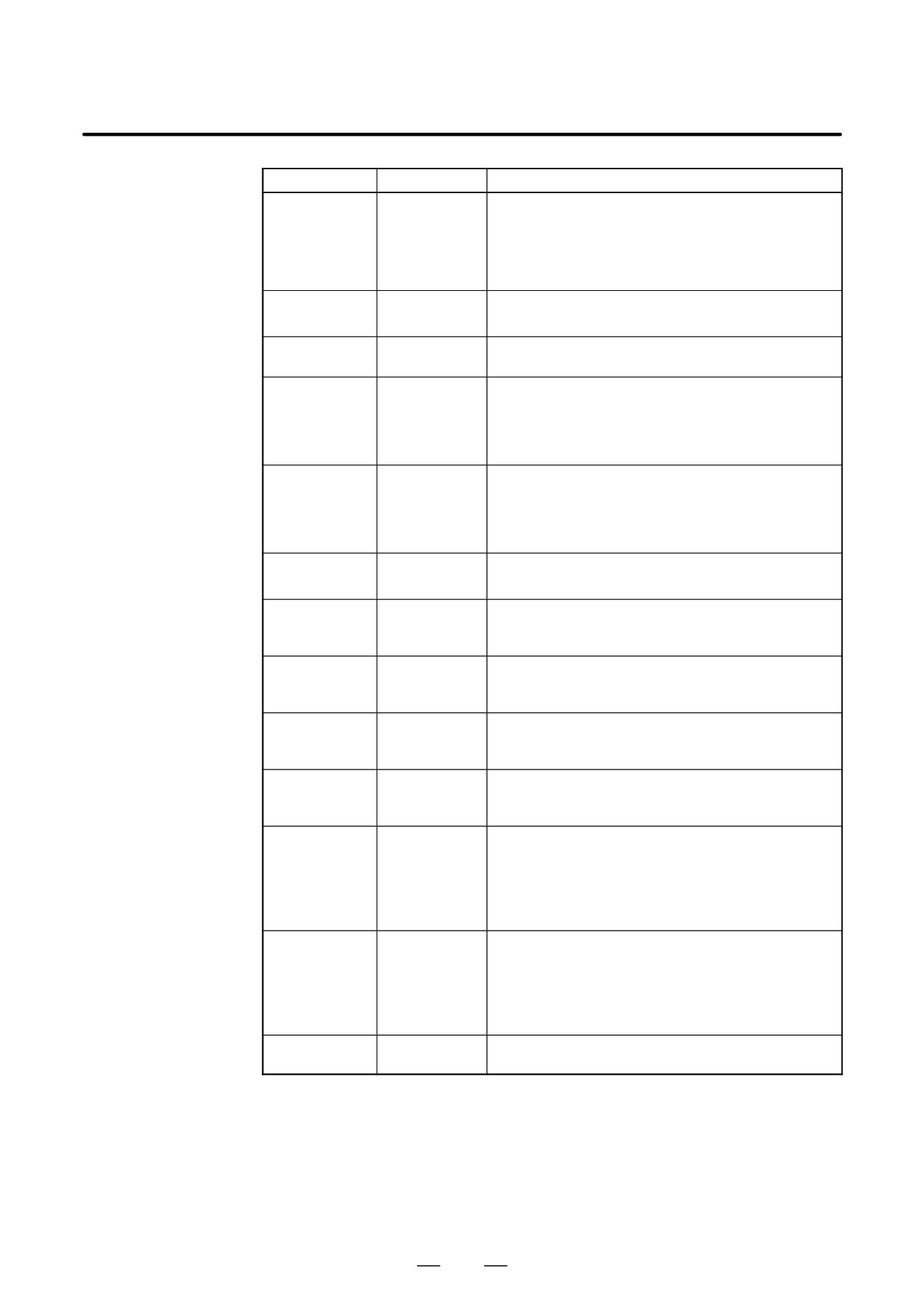
Symbol
Signal
Description
Used for orientation in which the stop position is specified
Orientation stop
externally.
position change
NRROA, B
0 : Rotational direction is set according to ROTA
short-cut com-
(= BIT01)
mand
1 : Short-cut control (within 180 degrees)
Analog over-
0 : Analog override is disabled.
OVRA, B
ride command
1 : Analog override is enabled.
Motor power
MPOFA, B
1 : Motor power stop
stop signal
R12I - R01I
SGN, SSIN
Spindle speed
SIND
Specifies a spindle speed command.
command
RI12 - RI00
RISGN
Stop position
command for
SHA11 - SHA00
The stop position is specified for the external setting type
spindle orienta-
SHB11 - SHB00
spindle orientation with the position coder.
tion with a posi-
tion coder
Spindle stop
0 : Velocity command voltage = 0
*SSTP
signal
1 : Velocity command voltage = specified value
Spindle
1 : Outputs the velocity command specified with the
SOR
orientation in
parameter.
progress
Specified
1 : The spindle speed has reached the specified
SAR
speed reached
speed.
signal
M function
FIN
completion sig-
1 : The M function is completed.
nal
Gear select
GR1, 2
Used for velocity command calculation under constant
signal (T-sys-
GS1, 2, 4
surface speed control
tem)
Spindle speed
synchroniza-
tion control
SPSYC
1 : Spindle speed synchronization control
command (Un-
der develop-
ment)
Spindle phase
synchroniza-
tion control
SPPHS
1 : Spindle phase synchronization control
command (Un-
der develop-
ment)
RGTP
Rigid tapping
1 : Rigid tapping control
RGTAP
command
* Valid only for αC spindle software 9D12 series.
414
B-65162E/03
10. INTERFACE SIGNALS
10.4.2
Spindle Control DO
Signals (CNC to PMC)
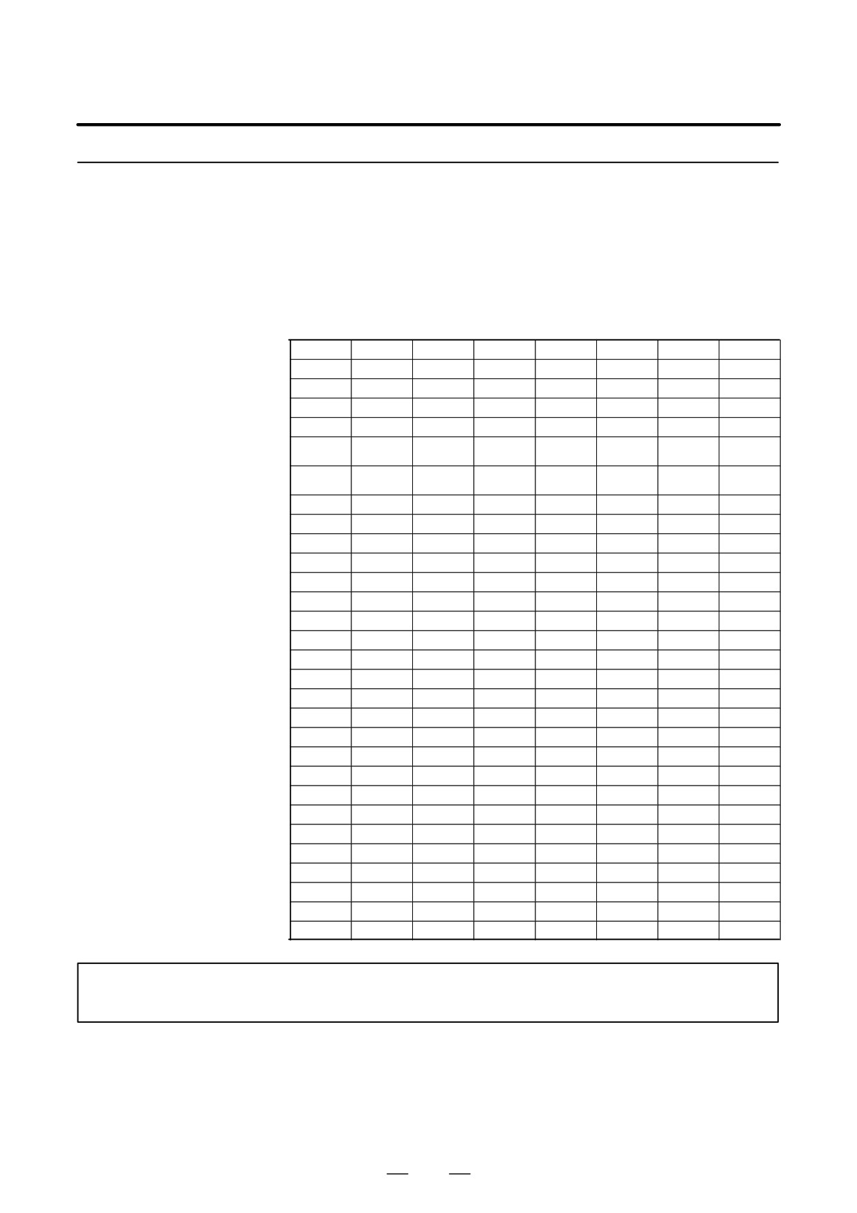
(1)
1st Spindle Signal Address
FS0-TT
FS0
FS15
FS16
#7
#6
#5
#4
#3
#2
#1
#0
HEAD2
F281
F1481
F229
F045
ORARA
TLMA
LDTA
SARA
SDTA
SSTA
ALMA
F282
F1482
F228
F046
F283
F1483
F231
F047
F172
F1372
F036
R08O
R07O
R06O
R05O
R04O
R03O
R02O
R01O
F173
F1373
F037
R12O
R11O
R10O
R09O
F010
RO15
RO14
RO13
RO12
RO11
RO10
RO09
RO08
(F006)
F011
RO07
RO06
RO05
RO04
RO03
RO02
RO01
RO00
(F007)
F150
F1350
F007
SF
MF
F008
SF
MF
F149
F1349
F001
ENB
F164
F1364
F038
ENB3
ENB2
F042
SPCO
SPBO
SPAO
SPAL
F154
F1354
F035
SPAL
F152
F1352
F034
GR30
GR20
GR10
F001
CSS
F002
CSS
F178
F044
SYCAL
FSPPH
FSPSY
F111
MSPPHS
MSPSYC
SPSYAL
F020
F025
S31
S30
S29
S28
S27
S26
S25
S24
F021
F024
S23
S22
S21
S20
S19
S18
S17
S16
F022
F023
S15
S14
S13
S12
S11
S10
S09
S08
F023
F022
S07
S06
S05
S04
S03
S02
S01
S00
F040
RTAP
F012
F041
AR15
AR14
AR13
AR12
AR11
AR10
AR09
AR08
F013
F040
AR07
AR06
AR05
AR04
AR03
AR02
AR01
AR00
F232
SLDM15
SLDM14
SLDM13
SLDM12
SLDM11
SLDM10
SLDM09
SLDM08
F233
SLDM07
SLDM06
SLDM05
SLDM04
SLDM03
SLDM02
SLDM01
SLDM00
F234
SSPD15
SSPD14
SSPD13
SSPD12
SSPD11
SSPD10
SSPD09
SSPD08
F235
SSPD07
SSPD06
SSPD05
SSPD04
SSPD03
SSPD02
SSPD01
SSPD00
F236
SSPAA7
SSPAA6
SSPAA5
SSPAA4
SSPAA3
SSPAA2
SSPAA1
SSPAA0
NOTE
The addresses in parentheses are used for 15-TT.
415
10. INTERFACE SIGNALS
B-65162E/03
(2)
2nd Spindle Signal Address
FS0-TT
FS0
FS15
FS16
#7
#6
#5
#4
#3
#2
#1
#0
HEAD2
F281
F1481
F229
F045
ORARB
TLMB
LDTB
SARB
SDTB
SSTB
ALMB
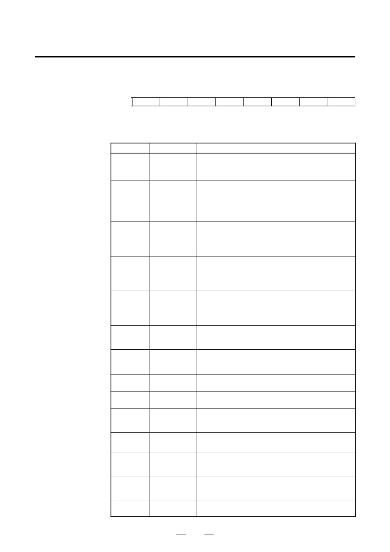
(3) Spindle control DO signals
Symbol
Signal
Description
Output when a spindle alarm occurs.
ALMA, B
Alarm signal
0 : Normal state
1 : Alarm state
Output when the output frequency of actual spindle amplifier
module becomes lower than the frequency stop detection
Frequency stop
level.
SSTA, B
detection signal
0 : Rotation state
1 : Frequency stop
Output when the output frequency of actual spindle amplifier
module does not exceed the preset amplifier frequency.
Frequency
SDTA, B
detection signal
0 : Higher than the specified speed
1 : Less than preset frequency
Output when the output frequency of actual spindle amplifier
module reaches the preset range.
Frequency
SARA, B
match signal
0 : Specified speed has yet to be reached
1 : Frequency match
Output when the detected load is greater than the specified
load detection level.
Load detection
LDTA, B
signal
0 : Lower than the specified load
1 : Greater than the specified load
Torque limiting
TLMA, B
signal (Under
1 : The limit is applied to the torque.
development)
Output when orientation was specified and the spindle has
Orientation
ORARA, B
stopped in the specified range.
complete signal
1 : Orientation completed
R12O-R01O
Spindle speed
Outputs the spindle speed command.
RO15-RO00
command
M function
MF
1 : The M code is effective.
strobe signal
Spindle func-
SF
tion strobe sig-
1 : The S code is effective.
nal
Spindle enable
0 : The velocity command indicates 0.
ENB
signal
1 : The velocity command indicates other than 0.
Spindle fluctua-
1 : The actual speed of the spindle is out of the allowed
SPAL
tion alarm sig-
range.
nal
Spindle speed
SPAO,
override check
SPBO SPCO
signal
Gear select
GR10, 20, 30
signal
416
B-65162E/03
10. INTERFACE SIGNALS
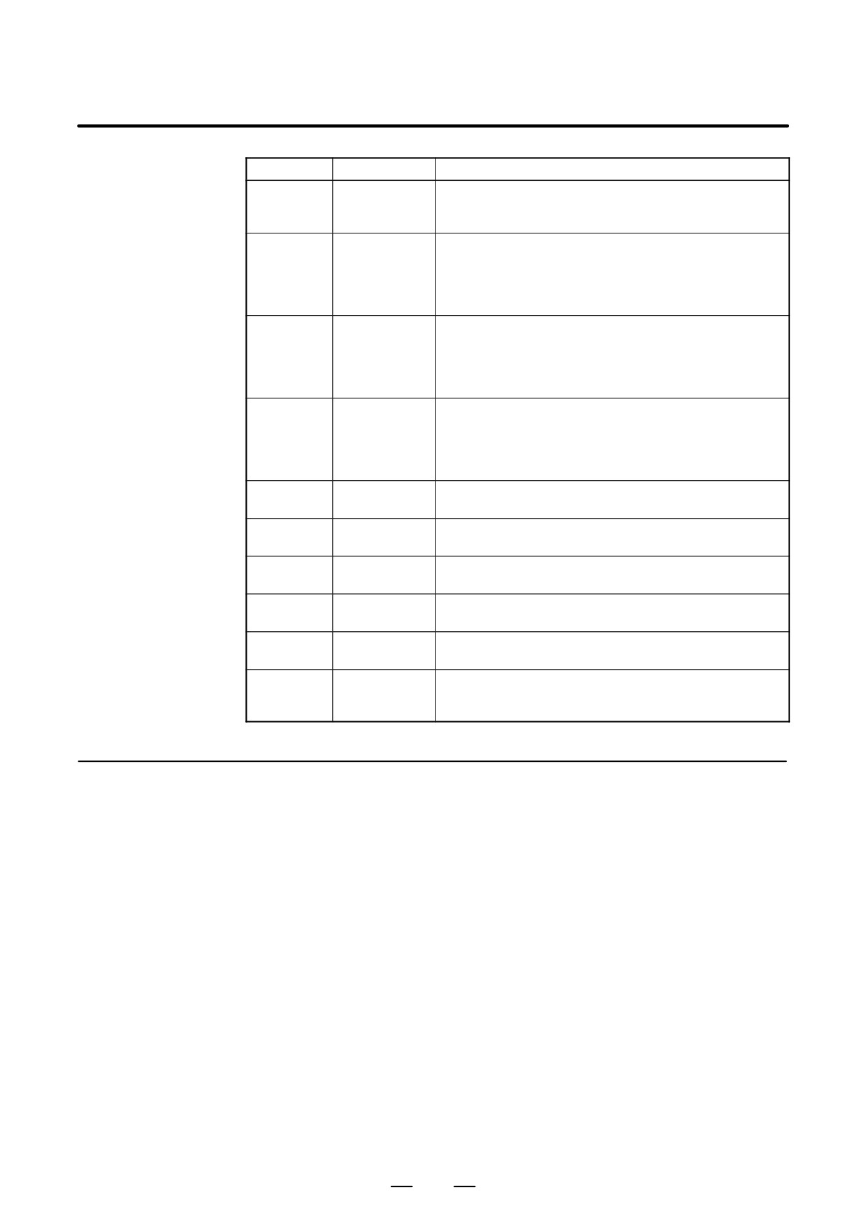
Symbol
Signal
Description
Constant sur-
CSS
face speed
1 : Under constant surface speed control
control signal
Spindle syn-
chronization
FSPSY
control signal
1 : Under spindle synchronization control
MSPSYC
(Under devel-
opment)
Spindle phase
synchroniza-
FSPPH
tion control sig-
1 : Under spindle phase synchronization control
MSPPHS
nal (Under de-
velopment)
Spindle syn-
chronization
SYCAL
control alarm
1 : Spindle synchronization control alarm
SPSYAL
signal (Under
development)
Spindle func-
S31 - S00
Sxxx
tion code signal
Actual spindle
AR15 - AR00
speed signal
SLDM15 -
Load meter
0 to 32767 (+10 V)
SLDM00
data
SSPD15 -
Motor frequen-
0 to 16383 (maximum motor speed)
SSPD00
cy data
SSPA07 -
Spindle alarm
Alarm number
SPMA00
data
Rigid tapping-
RTAP
in-progress
1 : Rigid tapping in progress
signal
10.4.3
Emergency Stop Signal D Spindle motor and spindle amplifier module enter the operable state
by *ESPA = 1. When *ESPA is set to 0, the spindle amplifier module
(*ESPA)
outputs the MCOFF signal and the spindle motor does not operate.
D If *ESPA = 0 is set during the motor rotation, the spindle motor
smoothly decelerates to a stop. Then, it outputs the MCOFF signal.
D If *ESPA = 1 then occurs again, the spindle motor enters the rotateable
state, and so will begin to rotate as soon as a rotation command is
issued. For this reason, the command signal (speed command, normal
operation command, or reverse operation command) to the spindle
amplifier module should be reset at the same time an emergency stop
signal is input.
417
10. INTERFACE SIGNALS
B-65162E/03
10.4.4
Machine Ready Signal
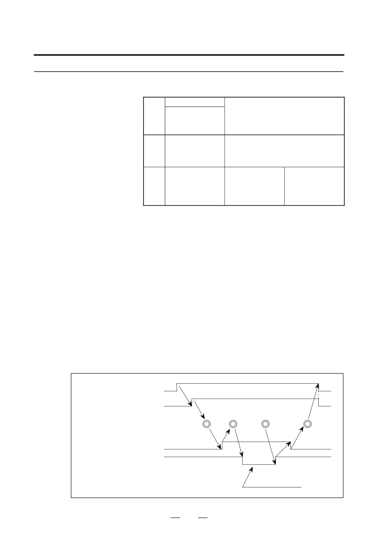
D The table contents result from the parameter setting.
(MRDYA)
Parameter setting
FS0 : 6501#0
Mode
FS12 : 3001#0
Contents
FS16 : 4001#0
Machine ready signal is not used.
At this time, the spindle motor enters the op-
A
0
erable state only when emergency stop sig-
nal is input.
Intercepts power by
Uses the machine
turning off the tran-
ready signal to
B
1
sistor excitation sig-
create operable state
nal for the inverter
by double signal.
with MRDYA = 0.
Mode A
Used when minimizing the input signal.
Mode B
1
During the automatic tool change (ATC) orientation operation, in a
machine where the spindle motor is restrained by the tool unclamp
signal,there are cases where the load meter indication becomes large
and a large motor current flows by a slight slip from the orientation
stop position.
In order to prevent this, set MRDYA = 0 and release the orientation
state during tool unclamp.
If MRDYA = 1 is set at tool unclamp end, it is possible to re-enter the
orientation state.
2
Regarding the purpose of the above described 1, if the orientation
command signal remains at ORCMA = 1, even if the machine ready
signal is set to MRDYA = 0/1, there is no orientation again after 1
rotation as it only moves by the amount of the stop position slip.
Timing chart
1
Orientation command
0
1
CRCMA
Orientation complete signal
0
ORARA
Pulling off
Attach-
Tool change operation
Tool
ment of
Tool catch
move
new tool
Detachment
OFF
Spindle unclamp
OFF
ON
Machine ready signal MRDYA
1
0
1
Excitation interception
418
B-65162E/03
10. INTERFACE SIGNALS
10.4.5
Normal Rotation
D When the following four conditions hold, the spindle motor starts a
normal rotation corresponding to the speed command (positive value).
Command Signal
During acceleration/deceleration (before a specified speed is reached),
(SFRA)
the motor speed increases or decreases according to an
acceleration/deceleration constant specified in the parameters listed
below. The acceleration/deceleration constant can take four different
values depending on the clutch/gear signals (CTH1 and CTH2).
- Emergency stop signal *ESPA is 1
- Machine ready signal MRDYA is 1
- Normal rotation command signal SFRA is 1
- Contact signal ESP is connected to 24 V (at CX4 of the PSM)
Parameter
DI signal
CTH
CTH
Contents
FS0
FS15
FS16
1A
2A
An acceleration/deceleration
6569
3069
4069
0
0
constant is specified. It can
6709
3209
take four different values de-
pending on the CTH1
and
6570
3070
CTH2 signals.
4070
0
1
6710
3210
Unit : 1rpm/sec
(Series16:
10 rpm unit when
4006#bit2=1)
6571
3071
Data range : 0 to 32767
4071
1
0
6711
3211
(Motor does not rotate when 0 is
set)
Standard setting : Depends on
6572
3072
4072
1
1
motor model
6712
3212
(Initial setting=900)
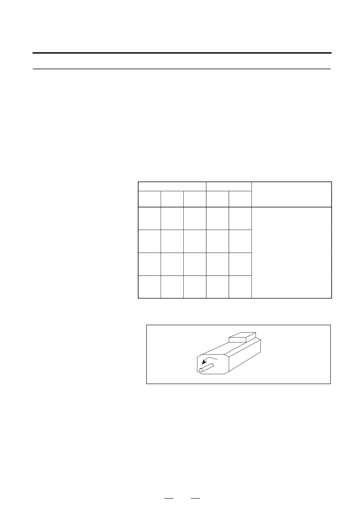
D While SFRA = 1, the spindle motor rotates in the counterclockwise
direction
(CCW) viewed from the shaft side according to the
commanded speed (positive value).
D If SFRA = 0 occurs, the spindle motor stops by the regenerative
braking. After stopping, it cuts the power supply to the spindle motor
by intercepting the transistor excitation signal.
419
10. INTERFACE SIGNALS
B-65162E/03
10.4.6
D When the following four conditions hold, the spindle motor starts a
Reverse Rotation
reverse rotation by the positive speed command.
Command Signal
During acceleration/deceleration (before a specified speed is reached),
(SRVA)
the motor speed increases or decreases according to an acceleration
/deceleration constant specified in parameters. See Section 10.4.5 for
detailed descriptions about acceleration/deceleration constants.
- Emergency stop signal *ESPA is 1
- Machine ready signal MRDYA is 1
- Reverse rotation command signal SRVA is 1
- Contact signal ESP is connected to 24 V (at CX4 of the PSM)
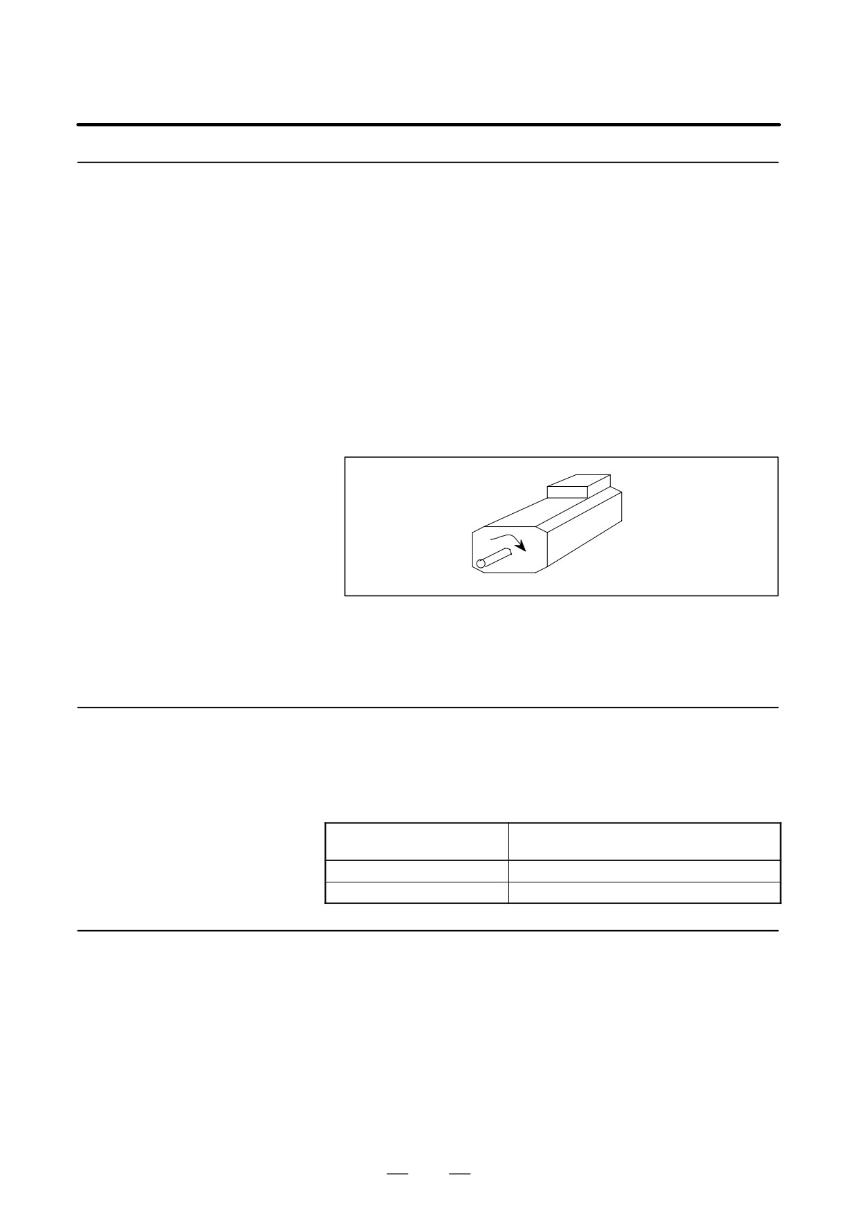
D While SRVA=1, the spindle motor rotates in a clockwise direction
(CW) looked at from the shaft side according to the speed command
(Positive value).
D When SRVA = 0, the spindle motor is stopped by regenerative
discharge braking. When the spindle motor comes to a stop, the
exciting signal for the power device is turned off to shut off the power
to the spindle motor.
10.4.7
Torque Limiting
D The torque restriction (torque limit) is used in order to rotate the
spindle motor to temporarily reduce the spindle motor output torque.
Command Signal
D The torque limit value change with parameter (Series 16 : PRM4025)
(TLMHA) (Under
and DI signal.
development)
Torque limit command
Torque limit value
TLMHA
0
Without torque limit
1
Limit to the parameter value
10.4.8
D After removing the various alarm causes such as motor overheating,
Alarm Reset Signal
excess speed deviation, short-circuiting, excess speed, excess voltage,
(ARSTA)
excess current, excess load, and voltage drop, if the alarm reset signal
is input, the alarm is released and the usable state occurs.
D Even if this signal is inputted when there is no alarm, it is disabled.
D This signal can reset only alarms related to the spindle amplifier
module. It cannot reset alarms related to the power supply module
(such as DC link overvoltage or undervoltage); such alarms are reset
by turning off the power.
420
B-65162E/03
10. INTERFACE SIGNALS
10.4.9
Spindle Alarm Signal
D If the state occurs in which the spindle motor operation cannot be
continuously executed, the power to the spindle motor will become
(ALMA)
OFF and the spindle motor will be stopped.
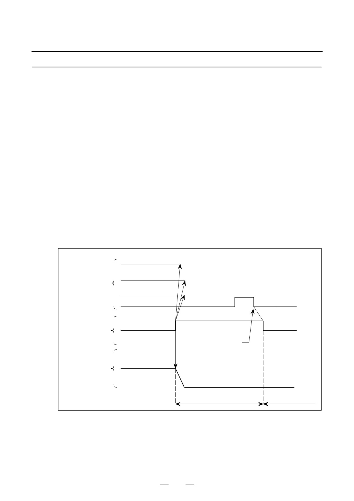
D At the same time the alarm signal ALMA = 1 occurs. Regarding the
alarm contents, confirm by the display section of the spindle amplifier.
D Set the command signal to the spindle amplifier (speed command,
forward/reverse rotation command, torgue limit command, spindle
orientation command ) in the reset state using the alarm signal output.
If it is not in the reset state (state that signal from PMC is all clear),
when the alarm on the spindle amplifier is released there is a danger
that the spindle motor may rotate.
D Because the spindle motor enters the power OFF, coasting operates at
the same time as the alarm signal is output, it is necessary to set in an
emergency stop state and to set the feedhold state at the CNC or
magnetics cabinet side.
D When the alarm state has occurred, ALMA = 1 occurs.
While the alarm signal is 1, the spindle motor enters coasting operates
state regardless of any command from the outside.
D The relationship between the alarm signal and the alarm reset signal
is as shown in Fig. 10.4.9.
Speed command
Forward rotation/back
rotation command
SFRA (SRVA)
Spindle control
input signal
Spindle orientatin
1
commandORCMA
0
0
ARSTA
(Alarm reset)
1
0
Spindle control
ALMA
output signal
(Alarm)
Remove the alarm cause
Motor rotation speed
Motor operation
(Stop)
Does not operate even
Usable state
when there is a command
Fig.10.4.9 Timing Chart of the Spindle Alarm Signal
421
10. INTERFACE SIGNALS
B-65162E/03
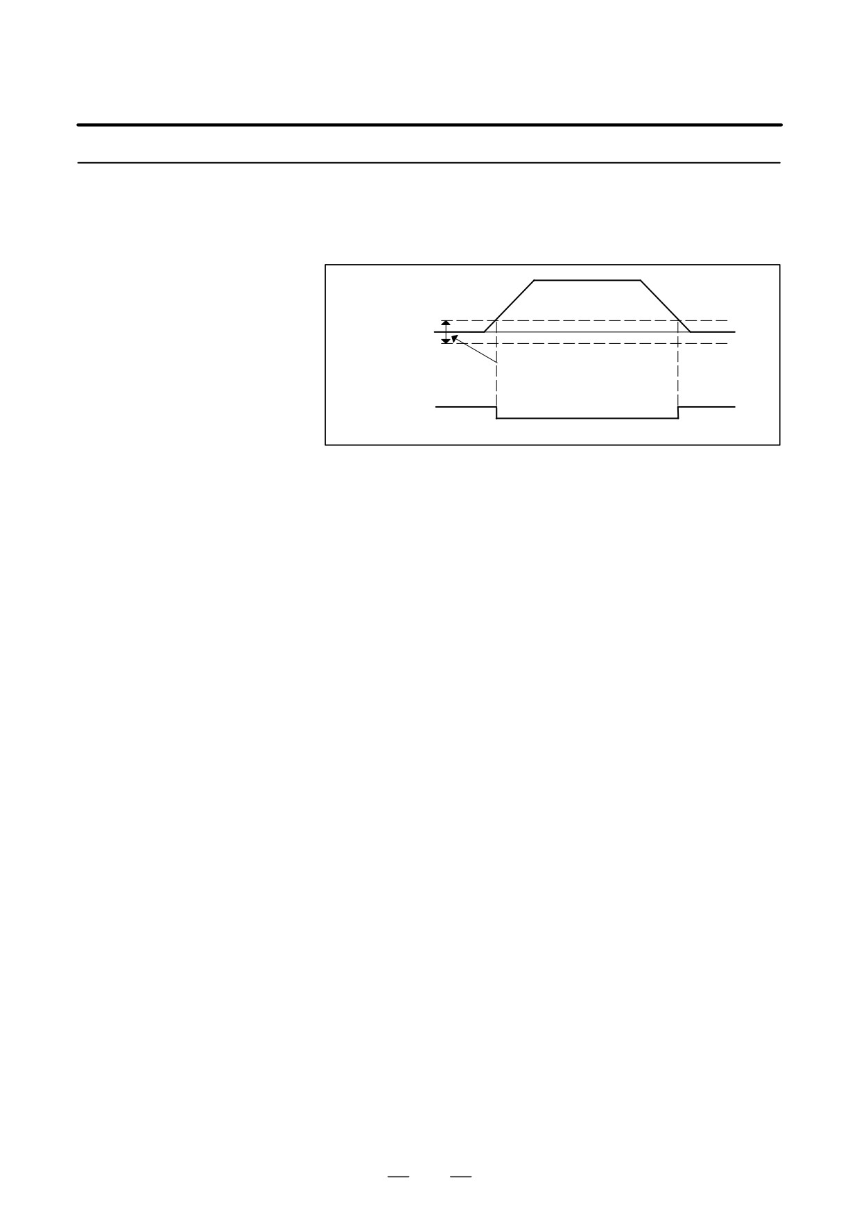
10.4.10
Frequency-stop
D If the output frequency of the actual spindle amplifier module is
reduced to be lower than the frequency stop detection point for the stop
Detecting Signal
command, SSTA = 1 occurs.
(SSTA)
Output
0
frequency
Frequency stop detection point
("0.75%of maximum
frequency as the standard)
SSTA (1)
(1)
(0)
Fig.10.4.10 Signal Indicating that the frequency dropped to
close to zero
D The frequency stop detection point is
0.75% of the maximum
frequency (standard initial setting for the parameter).
In other words, the frequency stop detection signal becomes SSTA =
1 when the frequency is lower than the detection level.
D This signal is output when the above condition is satisfied, irrespective
of rotation commands (SFRA, SRVA).
D The minimum pulse width value of this signal is about 40 ms.
422