FANUC SERVO AMPLIFIER a series. DESCRIPTIONS (B-65162E/03) - page 13
B-65162E/03
9.CONNECTION
363
9. CONNECTION
B-65162E/03
9.4.3
Spindle Amplifier
Modules
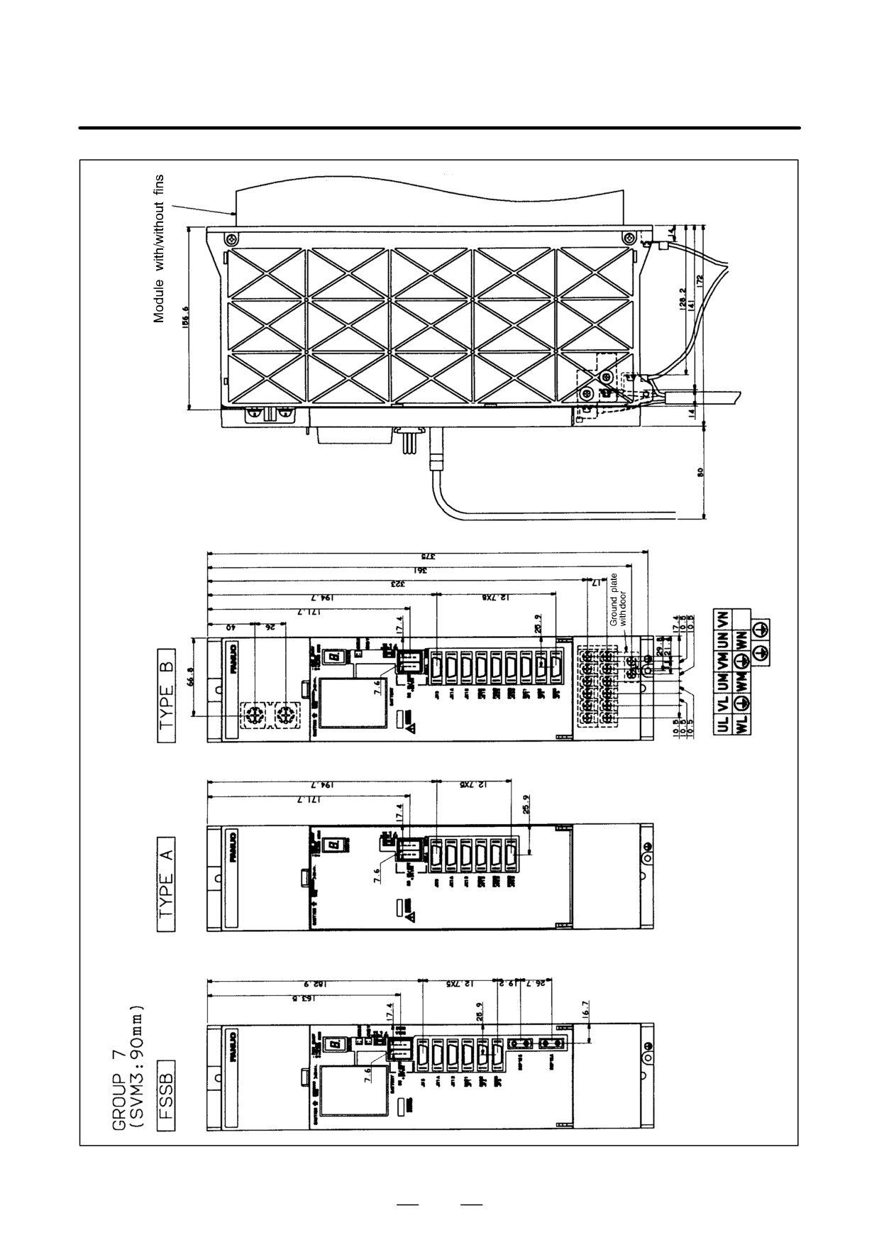
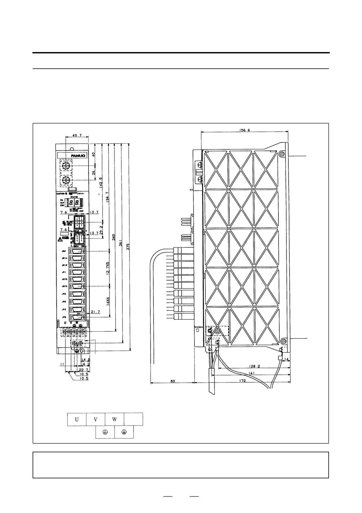
(1) SPM-2.2 (TYPE 1, 2, 4)
Grounding plate
supplied with the
module
Terminal board (TB2)
NOTE
Type 1 is not equipped with connector JY5.
364
B-65162E/03
9.CONNECTION
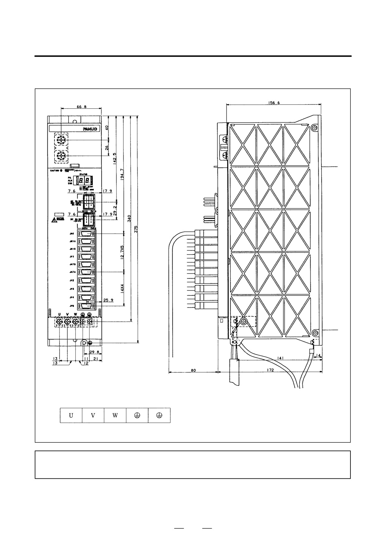
(2) SPM-5.5, 11, SPM-11HV (TYPE 1, 2, 4)
Terminal board (TB2)
NOTE
Type 1 is not equipped with connector JY5.
365
9. CONNECTION
B-65162E/03
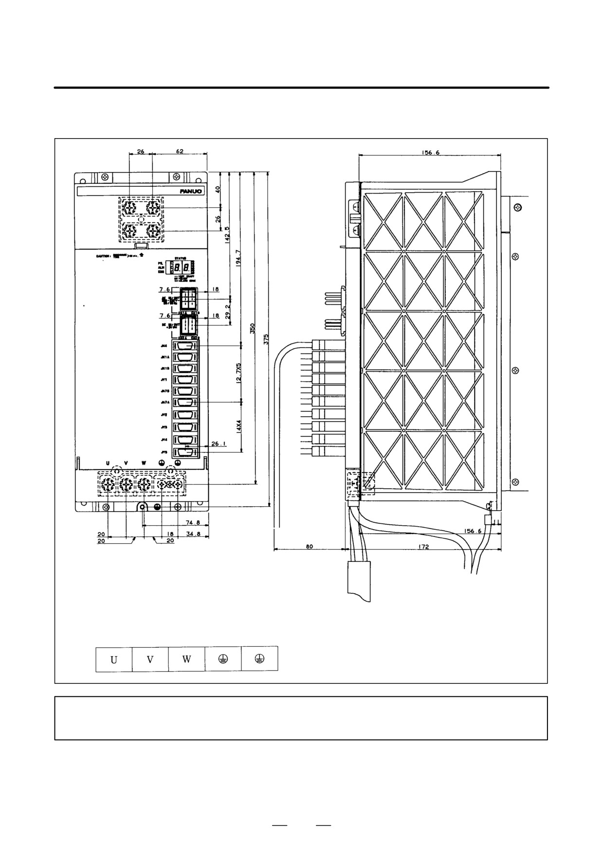
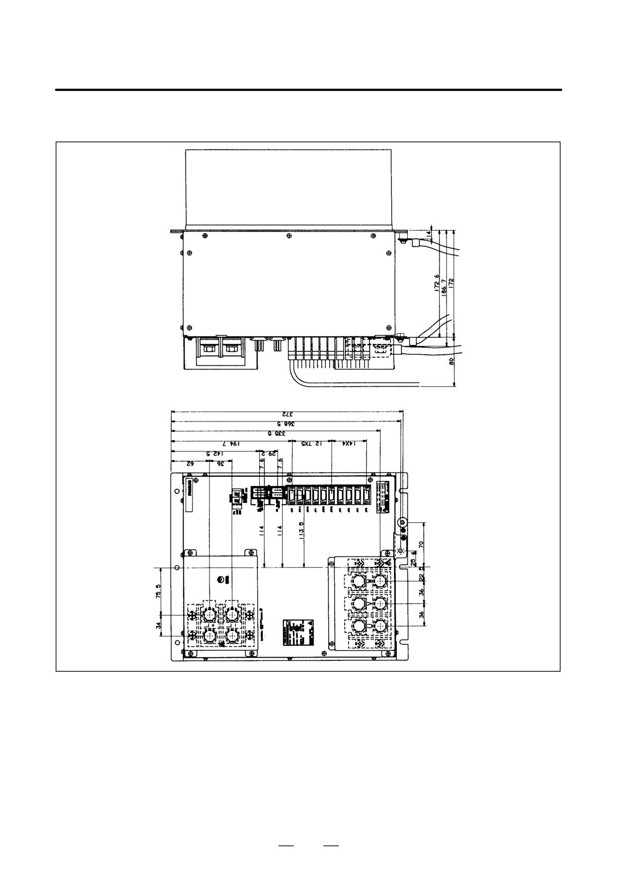
(3) SPM-15, 22, 26, 30, SPM-15HV, 26HV, 45HV (TYPE 1, 2, 4)
Terminal board (TB2)
NOTE
Type 1 is not equipped with connector JY5.
366
B-65162E/03
9.CONNECTION
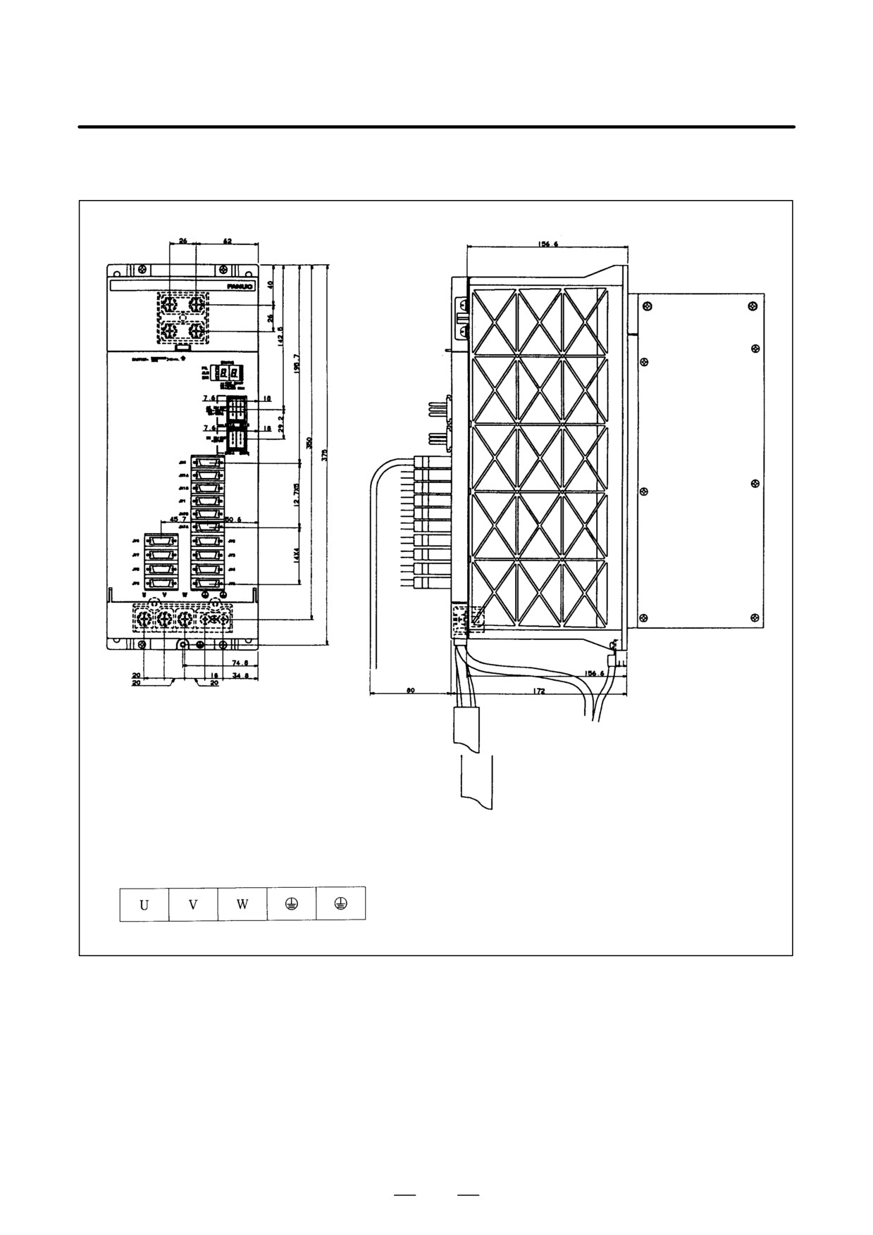
(4) SPM-45, SPM-75HV (TYPE 1, 2, 4)
367
9. CONNECTION
B-65162E/03
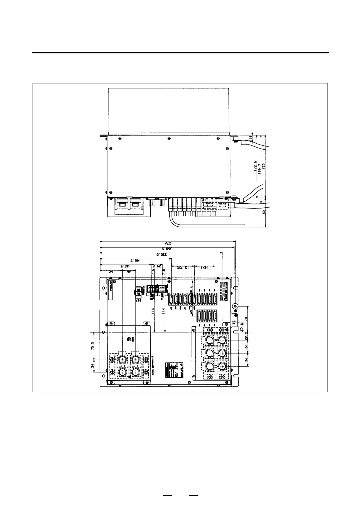
(5) SPM-11, 15, 22, 26, 30 (TYPE 3)
Terminal board (TB2)
368
B-65162E/03
9.CONNECTION
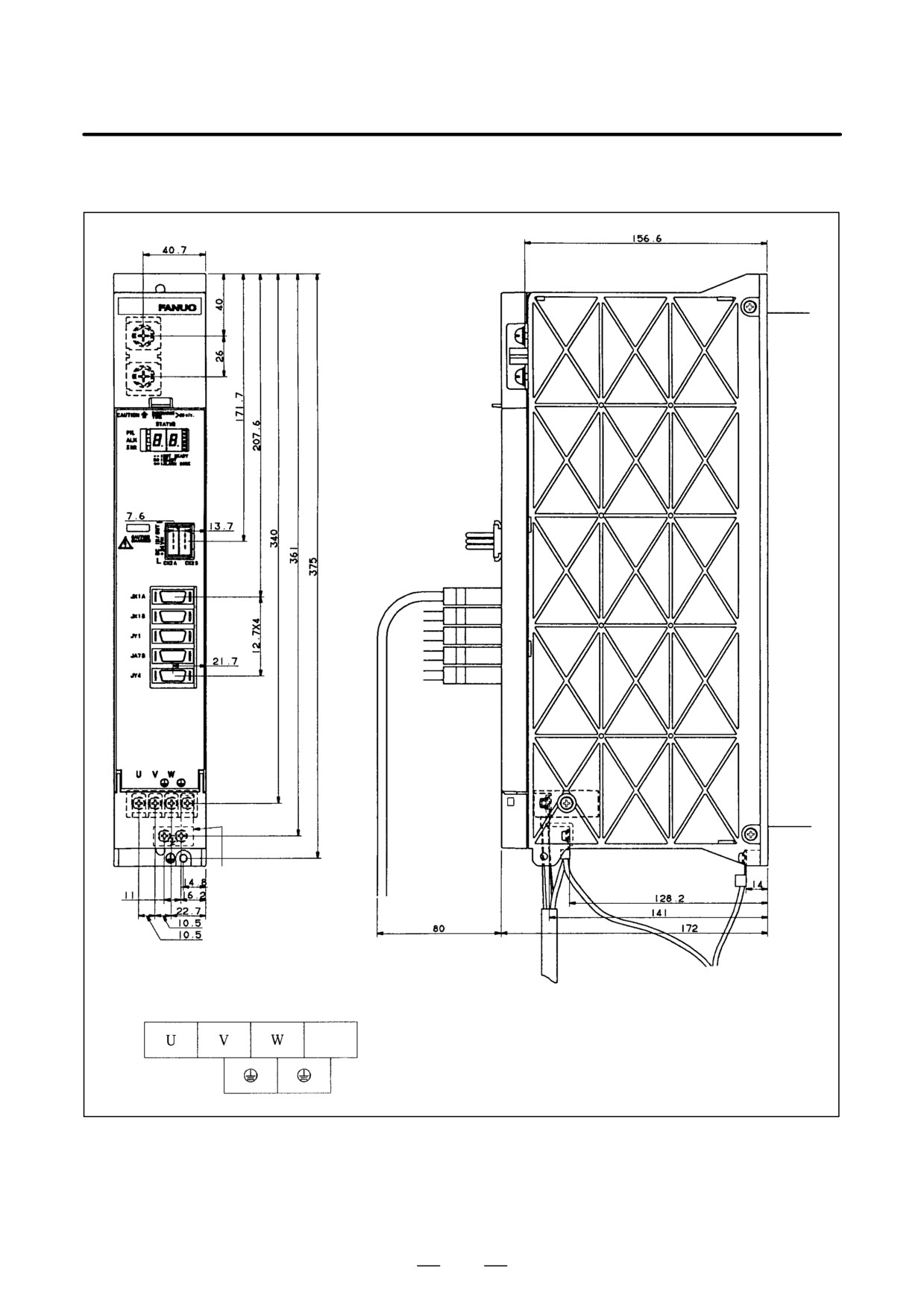
(6) SPM-45, SPM-75HV (TYPE 3)
369
9. CONNECTION
B-65162E/03
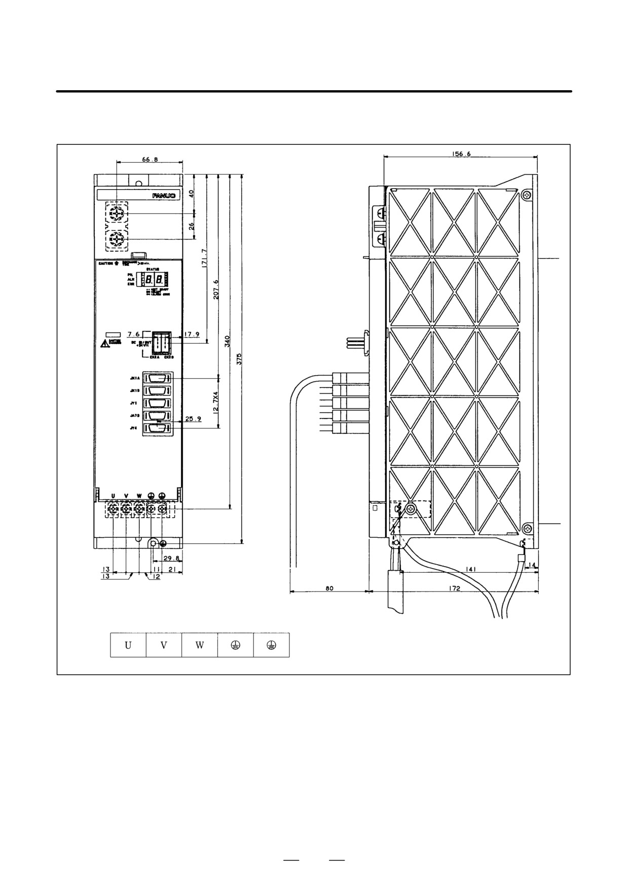
(7) SPMC-2.2
Grounding plate
supplied with the
module
Terminal board (TB2)
370
B-65162E/03
9.CONNECTION
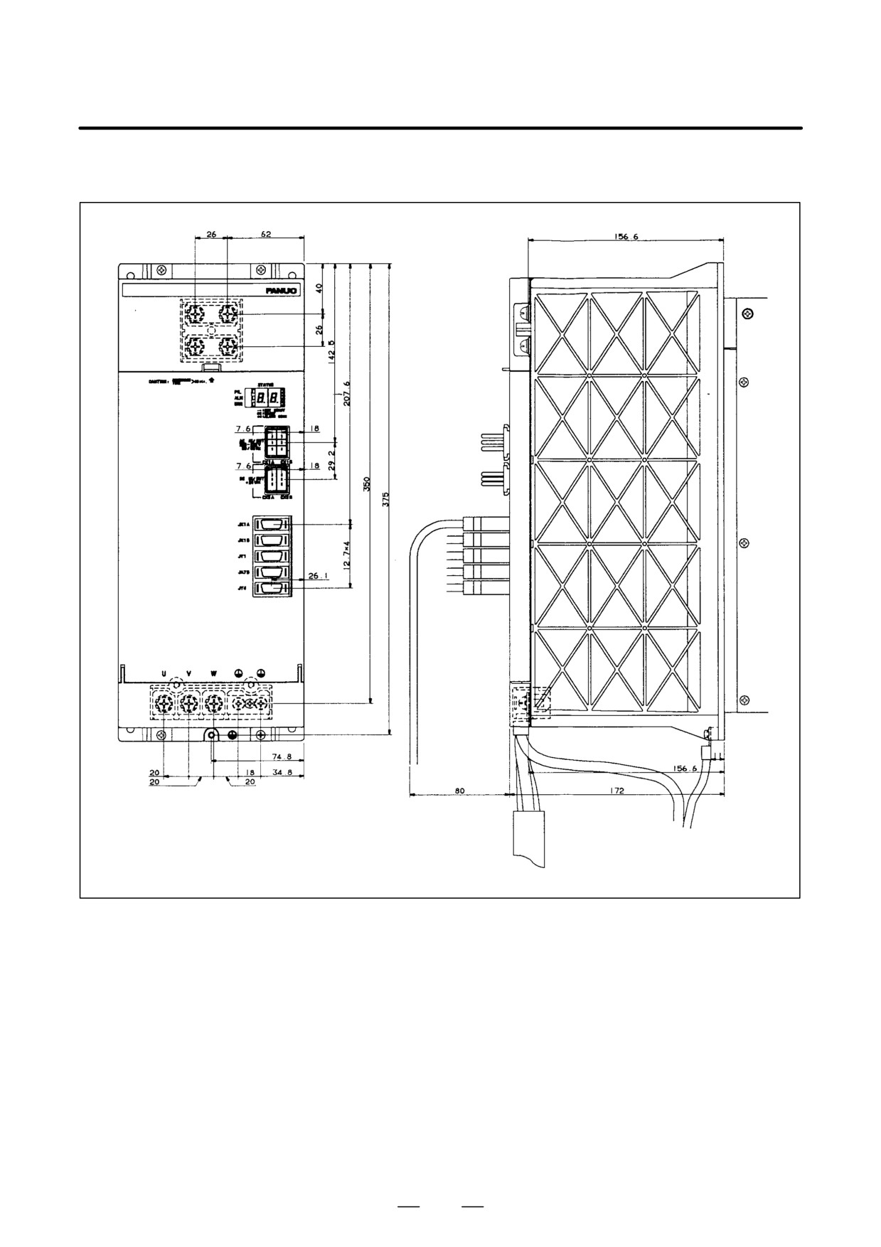
(8) SPMC-5.5, 11
Terminal board (TB2)
371
9. CONNECTION
B-65162E/03
(9) SPMC-15, 22, 26
372
B-65162E/03
10. INTERFACE SIGNALS
INTERFACE SIGNALS
10
373
10. INTERFACE SIGNALS
B-65162E/03
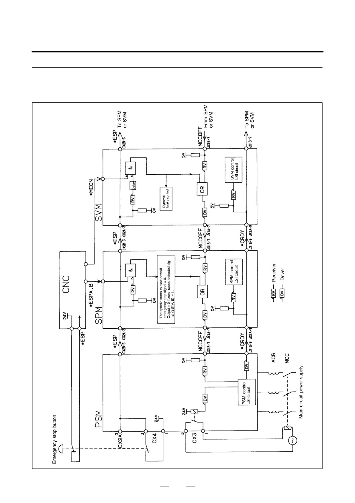
The α series servo amplifier has a terminal for the emergency stop signal
10.1
on the power supply module (connector: CX4). Always use the
EMERGENCY STOP
emergency stop signal.
SIGNAL (*ESP)
D When the contact is closed (on), the spindle motors and servo motors
- CONTACT INPUT
can operate. When the contact is open (off), the external magnetic
SIGNAL -
contactor is turned off, preventing operation of the spindle motors and
servo motors.
D When the contact is opened (turned off) while a motor is rotating, a
spindle motor will decelerate naturally and stop, while a servo motor
will stop by the application of its dynamic brake.
D The contact input signal has the following specifications:
- External contact capacity: 30 VDC or higher, 100 mA or higher
- Significant levels for contactless input (voltage between input
terminals)
Low (logical 0) : 2 V or lower
High (logical 1) : 20 V or higher
374
B-65162E/03
10. INTERFACE SIGNALS
10.1.1
Emergency Stop Signal
(*ESP) Block Diagram
375
10. INTERFACE SIGNALS
B-65162E/03
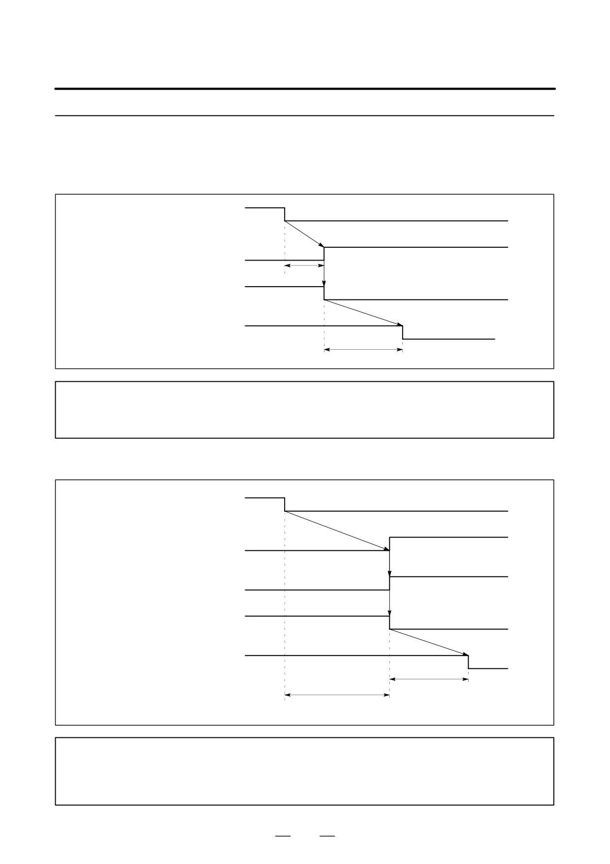
10.1.2
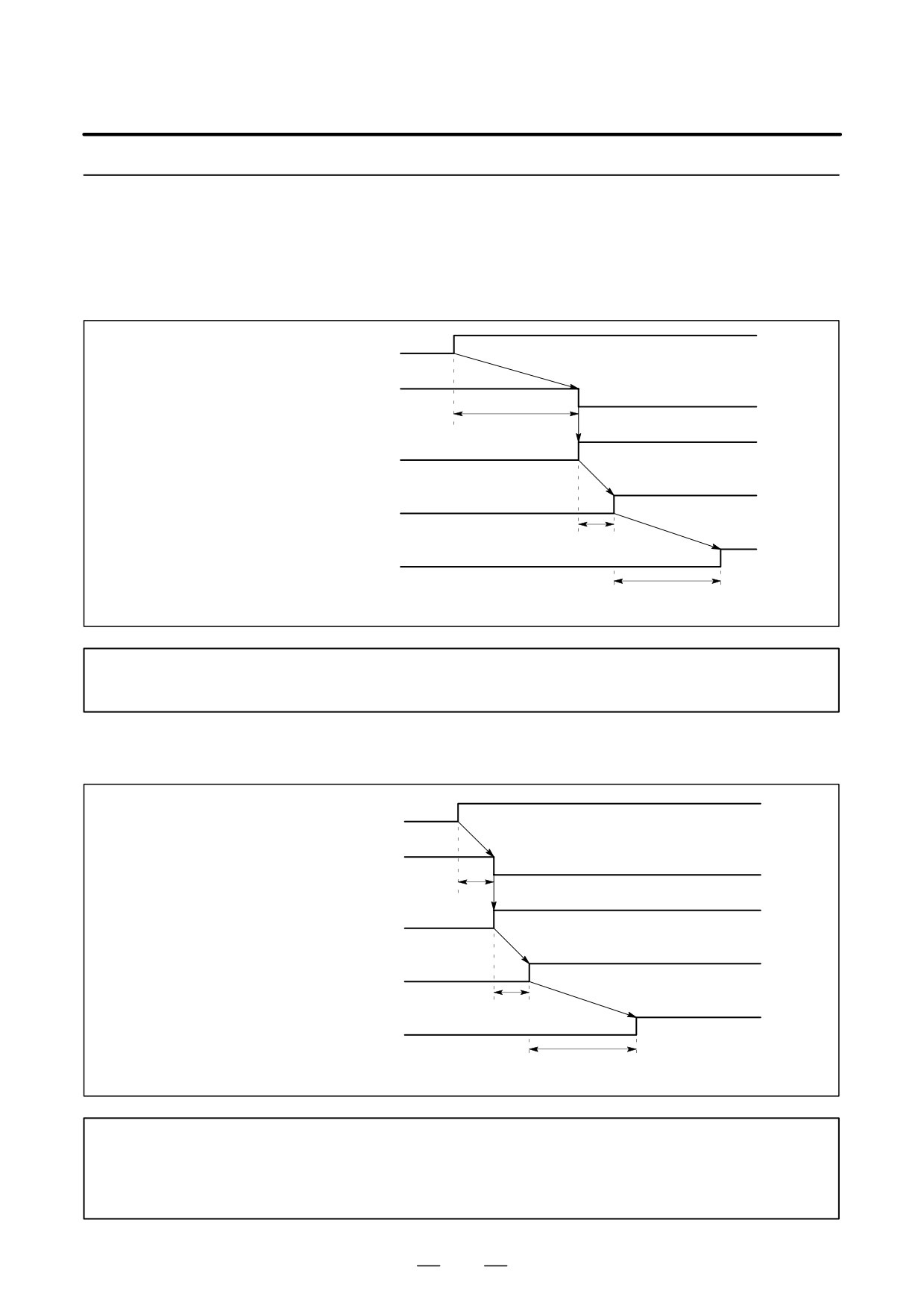
Sequence for
Emergency Stop
Without SPM
Emergency stop
contact signal (*ESP)
MCC OFF signal
(PSM/JX1B-7)
50 ms max.
Relay signal for controlling
external MCC (CX3)
ON
MCC contact
OFF
100ms max.
NOTE
The emergency stop signal triggers the DB stop sequence of the servo motor. At the same time,
each SVM outputs the MCCOFF signal to shut down the external MCC.
With SPM
Emergency stop
contact signal (*ESP)
Decelerating spindle
motor (SSTA, B)
MCC OFF signal
(PSM/JX1B-7)
Relay signal for controlling
external MCC (CX3)
ON
MCC contact
OFF
100ms max.
Decelerating
spindle motor
NOTE
The emergency stop signal brings the servo motor to a DB stop. It also decelerates the spindle
motor until it stops. Once the spindle motor has stopped, and the spindle zero-speed detected
signal has been output, the external MCC is shut down.
376
B-65162E/03
10. INTERFACE SIGNALS
10.1.3
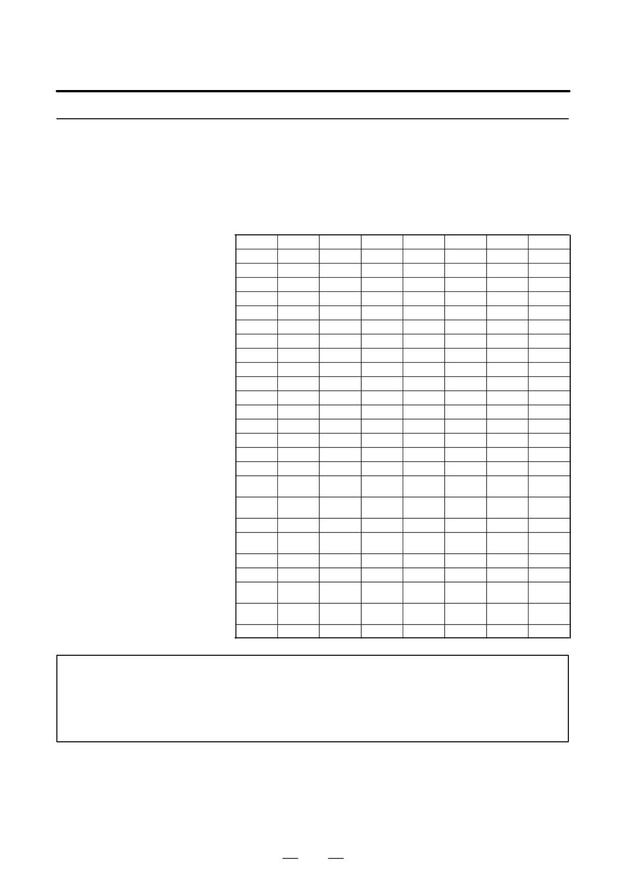
Sequence for
Releasing Emergency
Stop
Without SPM
Emergency stop
contact signal (*ESP)
MCC OFF signal
(PSM/JX1B-7)
2 s
ON
Relay signal for controlling
OFF
external MCC (CX3)
ON
OFF
MCC contact
100ms max.
PSM ready signal
(CRDY/JX1B-9)
1.5 s max.
Charging DC link
NOTE
When the PSM ready (*CRDY) signal = 0, the servo motor is ready to operate.
With SPM
Emergency stop
contact signal (*ESP)
MCC OFF signal
(PSM/JX1B-7)
16 ms
Relay signal for controlling
external MCC (CX3)
ON
OFF
MCC contact
100ms max.
PSM ready signal
(*CRDY/JX1B-9)
1.5 s max
Charging DC link
NOTE
When the PSM ready (*CRDY) signal = 0, the servo motor and spindle motor are ready to
operate. Even if there is an SPM, a no-SPM sequence is used, if the spindle emergency stop
signals (*ESPA and *ESPB) are not reset.
377
10. INTERFACE SIGNALS
B-65162E/03
10.2
SPINDLE CONTROL
SIGNALS (α series
spindle)
378
B-65162E/03
10. INTERFACE SIGNALS
10.2.1
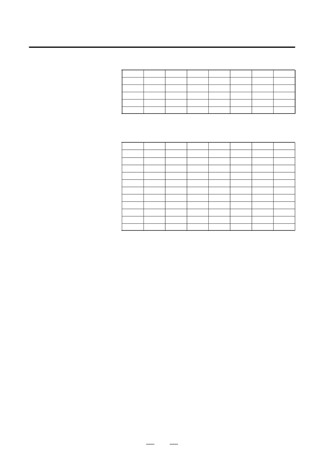
Spindle Control DI
Signal (PMC to CNC)
(1)
1st Spindle Signal Address
FS0-TT
FS15
FS16
FS0
#7
#6
#5
#4
#3
#2
#1
#0
HEAD2
(Note 1)
Path 1
Path 2
G229
G1429
G227
G070
G1070
MRDYA
ORCMA
SFRA
SRVA
CTH1A
CTH2A
TLMHA
TLMLA
G230
G1430
G226
G071
G1071
RCHA
RSLA
INTGA
SOCNA
MCFNA
SPSLA
*ESPA
ARSTA
G231
G1431
G229
G072
G1072
RCHHGA
MFNHGA
INCMDA
OVRA
DEFMDA
NRROA
ROTAA
INDXA
G232
G1432
G228
G073
G1073
DSCNA
SORSLA
MPOFA
SLVA
MORCMA
G124
G1324
G032
G1032
R08I
R07I
R06I
R05I
R04I
R03I
R02I
R01I
G125
G1325
G033
G1033
SIND
SSIN
SGN
R12I
R11I
R10I
R09I
G024
RISGN
RI12
RI11
RI10
RI09
RI08
G025
RI07
RI06
RI05
RI04
RI03
RI02
RI01
RI00
G110
G1310
G231
G078
G1078
SHA07
SHA06
SHA05
SHA04
SHA03
SHA02
SHA01
SHA00
G111
G1311
G230
G079
G1079
SHA11
SHA10
SHA09
SHA08
G103
G1303
SPC
SPB
SPA
G029
SPC
SPB
SPA
G030
G1030
SOV7
SOV6
SOV5
SOV4
SOV3
SOV2
SOV1
SOV0
G120
G1320
*SSTP
SOR
SAR
FIN
G005
FIN
G029
G1029
*SSTP
SOR
SAR
G004
G1004
FIN
G123
G1323
CON(M)
SPSTP
*SCPF
*SUCPF
GR2
GR1
COFF(T)
(Note 2)
G118
G1318
GR2
GR1
(Note 1)
G027
G1027
CON
G067,
SCNTR
071, ...
1, 2, ...
G146
G038
G1038
SPPHS
SPSYC
G111
SPPHS
SPSYC
G123
RGTP
(Note 3)
G135
G061
G1061
RGTAP
(Note 3)
G026
GS4
GS2
GS1
*SECLP
*SEUCL
SPSTP
NOTE
1
The addresses listed under ”FS15” are for the PMC-NA. Refer to the FS15 Connection Manual
for the PMC-NB addresses.
2
Bit 5 (ADDCF) of parameter No. 31 applies here.
3
Bit 4 (SRGTP) of parameter No. 19 applies here.
379
10. INTERFACE SIGNALS
B-65162E/03
FS0-TT
FS15
FS16
FS0
#7
#6
#5
#4
#3
#2
#1
#0
HEAD2
(Note 1)
Path 1
Path 2
G028
G1028
SPSTP
*SCPF
*SUCPF
GR2
GR1
G104
ESRSYC
G145
G1345
GR31
GR21
*SSTP3
*SSTP2
*SSTP1
SWS3
SWS2
SWS1
G027
G1027
*SSTP3
*SSTP2
*SSTP1
SWS3
SWS2
SWS1
G029
G1029
GR31
GR21
G146
G1346
G028
G1028
PS2SLC
(2)
2nd Spindle Signal Address
FS0-TT
FS15
FS16
FS0
#7
#6
#5
#4
#3
#2
#1
#0
HEAD2
(Note 1)
Path 1
Path 2
G233
G1433
G235
G074
G1074
MRDYB
ORCMB
SFRB
SRVB
CTH1B
CTH2B
TLMHB
TLMLB
G234
G1434
G234
G075
G1075
RCHB
RSLB
INTGB
SOCNB
MCFNB
SPSLB
*ESPB
ARSTB
G235
G1435
G237
G076
G1076
RCHHGB
MFNHGB
INCMDA
OVRB
DEFMDB
NRROB
ROTAB
INDXB
G236
G1436
G236
G077
G1077
SORSLB
MPOFB
SLVB
MORCMB
G112
G1312
G239
G080
G1080
SHB07
SHB06
SHB05
SHB04
SHB03
SHB02
SHB01
SHB00
G113
G1313
G238
G081
G1081
SHB11
SHB10
SHB09
SHB08
G034
G1034
R08I2
R07I2
R06I2
R05I2
R04I2
R03I2
R02I2
R01I2
G035
G1035
SIND2
SSIN2
SGN2
R12I2
R11I2
R10I2
R09I2
G232
RISGNB
RIB12
RIB11
RIB10
RIB9
RIB8
G233
RIB7
RIB6
RIB5
RIB4
RIB3
RIB2
RIB1
RIB0
G106
G1306
M2R08I
M2R07I
M2R06I
M2R05I
M2R04I
M2R03I
M2R02I
M2R01I
G107
G1307
M2SIND
M2SSIN
M2SGN
M2R12I
M2R11I
M2R10I
M2R09I
380
B-65162E/03
10. INTERFACE SIGNALS
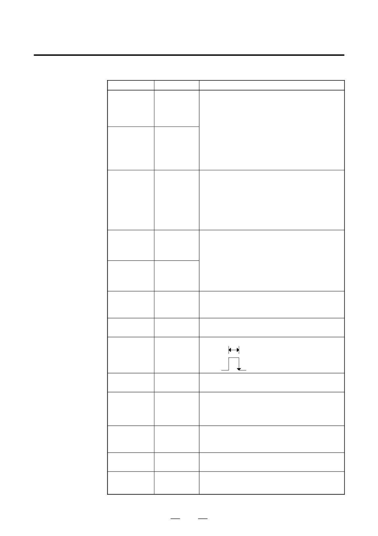
(3)
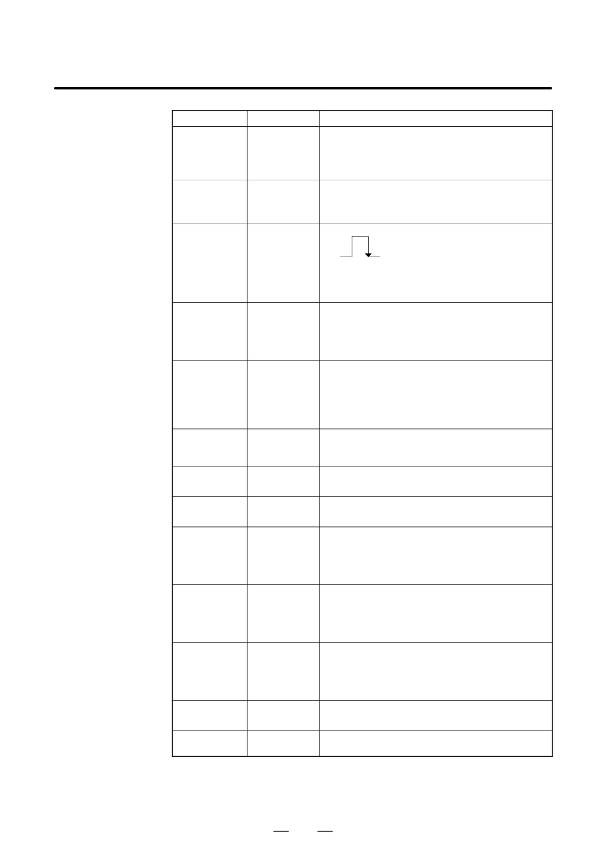
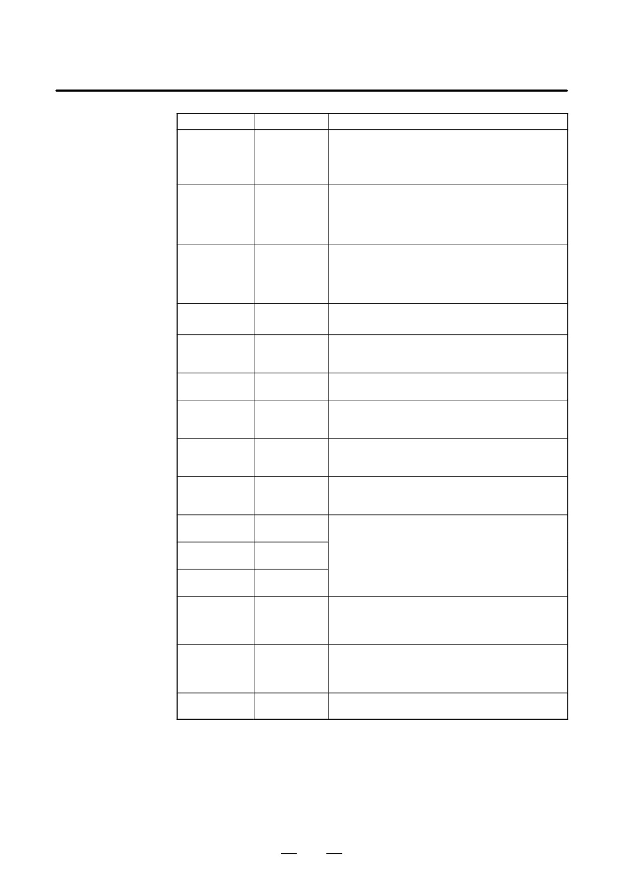
Spindle control DI signals
Symbol
Signal
Description
Limits the output torque of the spindle motor. Set the limit
using the spindle parameter.
Torque limit
TLMLA, B
command (low)
TLML TLMH
0
0
: No torque limit
0
1
: Limits the torque to the value
specified with the parameter.
Torque limit
1
0
: Limits the torque to half of the
TLMHA, B
command
value specified with the parameter.
(high)
1
1
: Limits the torque to half of the
value specified with the parameter.
Specify one of the following conditions according to the
clutch or gear status.
Used to select a spindle control parameter.
Clutch or gear
CTH1 CTH2
CTH1, 2A, B
signal
0
0
: High gear
0
1
: Medium high gear
1
0
: Medium low gear
1
1
: Low gear
Specifies the rotation direction when the spindle motor is
Reverse rota-
viewed from the shaft.
SRVA, B
tion command
SRV SFR
0
0
: Sto
0
1
: Normal rotation
Normal rotation
(CCW: Counterclockwise)
SFRA, B
command
1
0
: Reverse rotation (CW: Clockwise)
1
1
: Stop
Used for spindle orientation control.
Orientation
ORCMA, B
0 : -
command
1 : Spindle orientation control is performed.
Machine ready
0 : Motor is not excited.
MRDYA, B
signal
1 : Motor is ready for operation.
Used to reset the spindle alarm.
32 ms min.
Alarm reset sig-
ARSTA, B
nal
The alarm is reset when the level of
”1”
the signal is changed from 1 to 0.
”0”
Emergency
0 : Emergency stop
*ESPA, B
stop signal
1 : Normal operation
Used to select the spindle motor by spindle switcing con-
Spindle selec-
trol.
SPSLA, B
tion request
0 : Main spindle
signal
1 : Sub spindle
Used for the spindle switching control.
Power line
MCFNA, B
status check
0 : Main spindle
signal
1 : Sub spindle
Soft start/stop
0 : The soft start/stop function is canceled.
SOCNA, B
cancel signal
1 : The soft start/stop function is enabled.
Velocity inte-
0 : Velocity integral control is enabled.
INTGA, B
gral control sig-
1 : Velocity integral control is disabled.
nal
381
10. INTERFACE SIGNALS
B-65162E/03
Symbol
Signal
Description
Used to select the output characteristics in speed range
Speed range
swiching control.
RSLA, B
switching
0 : High-speed range
request signal
1 : Low-speed range
Used for the speed range switching function.
Power line sta-
RCHA, B
tus check sig-
0 : High-speed range
nal
1 : Low-speed range
Used for the stop position external
”1”
setting type orientation.
Orientation
New stop position data is obtained
”0”
INDXA, B
stop position
when the level of the signal is
change signal
changed from 1 to 0.
Then, the spindle is moved to the
new stop position, and is stopped.
Rotation direc-
Used for the stop position external setting type orienta-
tion command
tion.
ROTAA, B
while changing
0 : CCW (counterclockwise)
the orientation
1 : CW (clockwise)
stop position
Short-distant
Used for the stop position external setting type orienta-
movement
tion.
command while
NRROA, B
0 : The rotation direction depends on the setting of
changing the
ROTA (= bit 1)
orientation stop
1 : Short-distance movement control (within "180°)
position
Differential
Used for the spindle differential control mode
DEFMDA, B
mode com-
1 : Differential control mode
mand
Analog over-
0 : Analog override is disabled.
OVRA, B
ride command
1 : Analog override is enabled.
Incremental
1 : Incremental command spindle orientation
INCDA, B
command
0 : Normal orientation
Main-spindle
MCC status
0 : The MCC in the main spindle is opened.
MFNHGA, B
signal while
1 : The MCC in the main spindle is closed.
changing
spindles
High-speed
MCC status
0 : The MCC for high speed is opened.
RCHHGA, B
signal while
1 : The MCC for high speed is closed.
changing
speed range
Command for
spindle orienta-
1 : Spindle orientation with the magnetic sensor is con-
MORCMA, B
tion with a
trolled.
magnetic sen-
sor
Slave operation
0 : Slave operation control is disable.
SLVA, B
command
1 : Slave operation control is enable.
Motor power
MPOFA, B
1 : Motor power stop
stop signal
382
B-65162E/03
10. INTERFACE SIGNALS
Symbol
Signal
Description
Used if a feedback loop between the amplifier and motor
Broken-wire
is to be disconnected.
DSCNA, B
detection dis-
0 : Enables broken-wire and overheat detection.
able signal
1 : Disables broken-wire and overheat detection.
R12I - R01I
SGN, SSIN
Spindle speed
SIND
Specifies a spindle speed command.
command
RI12 - RI00
RISGN
Stop position
command for
SHA11 - SHA00
The stop position is specified externally spindle orienta-
spindle orienta-
SHB11 - SHB00
tion with the position coder.
tion with a posi-
tion coder
Spindle stop
0 : Velocity command voltage = 0
*SSTP
signal
1 : Velocity command voltage = specified value
Spindle
1 : Outputs the velocity command specified with the
SOR
orientation in
parameter.
progress
Velocity
1 : The actual spindle speed reaches the specified
SAR
reached signal
speed.
M function
FIN
completion sig-
1 : The M function is completed.
nal
Cs contour
CON, COFF
control com-
Specifies the Cs contour control mode .
SCNTR1, 2 . .
mand
Gear select
GR1, 2
Used for velocity command calculation under constant
signal (T-se-
GS1, 2, 4
surface speed control
ries)
*SUCPF
Spindle un-
*SEUSL
clamp signal
*SCPF
Spindle clamp
Used for spindle positioning control
*SEUCL
signal
Spindle stop
SPSTP
check signal
Spindle speed
synchroniza-
SPSYC
1 : Spindle speed synchronization control
tion control
command
Spindle phase
synchroniza-
SPPHS
1 : Spindle phase synchronization control
tion control
command
RGTP
Rigid tapping
1 : Rigid tapping control
RGTAP
command
383
10. INTERFACE SIGNALS
B-65162E/03
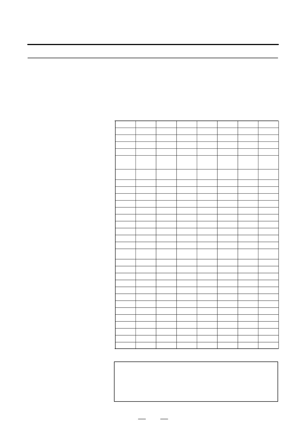
10.2.2
Spindle Control DO
Signals (CNC to PMC)
(1)
1st Spindle Signal Address
FS0-TT
FS15
FS16
FS0
#7
#6
#5
#4
#3
#2
#1
#0
HEAD2
(Note 1)
Path 1
Path 2
F281
F1481
F229
F045
F1045
ORARA
TLMA
LDT2A
LDT1A
SARA
SDTA
SSTA
ALMA
F282
F1482
F228
F046
F1046
MOAR2A
MOAR1A
POAR2A
SLVSA
RCFNA
RCHPA
CFINA
CHPA
F283
F1483
F231
F047
F1047
EXOFA
SORENA
MSOVRA
INCSTA
PC1DTA
F172
F1372
F036
F1036
R08O
R07O
R06O
R05O
R04O
R03O
R02O
R01O
F173
F1373
F037
F1037
R12O
R11O
R10O
R09O
F010
RO15
RO14
RO13
RO12
RO11
RO10
RO09
RO08
(F006)
(Note 2)
F001
RO07
RO06
RO05
RO04
RO03
RO02
RO01
RO00
(F001)
F150
F1350
F007
F1007
SF
MF
SF
MF
F149
F1349
F001
F1001
ENB
F164
F1364
F038
F1038
ENB3
ENB2
SCLP
SUCLP
SPCO
SPBO
SPAO
SPAL
SSLP
SUCLP
F154
F1354
F035
F1035
SPAL
F152
F1352
F034
F1034
GR30
GR20
GR10
F001
CSS
F002
F1002
CSS
F178
F044
F1044
SYCAL
FSPPH
FSPSY
FSCSL
F67, 71,
MCNTR1,
2, ...
F111
MSPPHS
MSPSYC
SPSYAL
F040
RTAP
F020
F025
F1025
S31
S30
S29
S28
S27
S26
S25
S24
F021
F024
F1024
S23
S22
S21
S20
S19
S18
S17
S16
F022
F023
F1023
S15
S14
S13
S12
S11
S10
S09
S08
F023
F022
F1022
S07
S06
S05
S04
S03
S02
S01
S00
F012
F041
F1041
AR15
AR14
AR13
AR12
AR11
AR10
AR09
AR08
F013
F040
F1040
AR07
AR06
AR05
AR04
AR03
AR02
AR01
AR00
F232
SLDM15
SLDM14
SLDM13
SLDM12
SLDM11
SLDM10
SLDM09
SLDM08
F233
SLDM07
SLDM06
SLDM05
SLDM04
SLDM03
SLDM02
SLDM01
SLDM00
F234
SSPD15
SSPD14
SSPD13
SSPD12
SSPD11
SSPD10
SSPD09
SSPD08
F235
SSPD07
SSPD06
SSPD05
SSPD04
SSPD03
SSPD02
SSPD01
SSPD00
F236
SSPAA7
SSPAA6
SSPAA5
SSPAA4
SSPAA3
SSPAA2
SSPAA1
SSPAA0
NOTE
1
The addresses listed under ”FS15” are for the PMC-NA.
Refer to the FS15 Connection Manual for the PMC-NB
addresses.
2 The addresses in parentheses are used for 15-TT.
384
B-65162E/03
10. INTERFACE SIGNALS
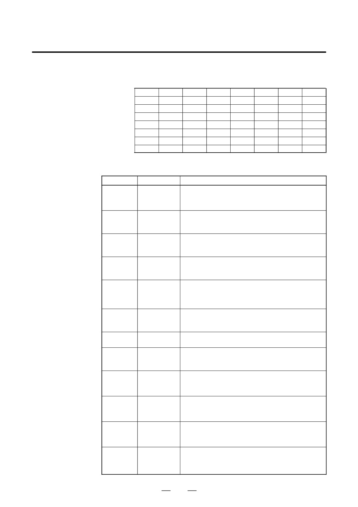
(2)
2nd Spindle Signal Address
FS0-TT
FS15
FS16
FS0
#7
#6
#5
#4
#3
#2
#1
#0
HEAD2
(Note 1)
Path 1
Path 2
F285
F1485
F245
F049
F1049
ORARB
TLMB
LDT2B
LDT1B
SARB
SDTB
SSTB
ALMB
F286
F1486
F244
F050
F1050
MOAR2B
MOAR1B
POAR2B
SLVSB
RCFNB
RCHPB
CFINB
CHPB
F287
F1487
F247
F051
F1051
EXOFB
SORENB
MSOVRB
INCSTB
PC1DTB
F248
SLDMB15
SLDMB14
SLDMB13
SLDMB12
SLDMB11
SLDMB10
SLDMB9
SLDMB8
F249
SLDMB7
SLDMB6
SLDMB5
SLDMB4
SLDMB3
SLDMB2
SLDMB1
SLDMB0
F250
SSPDB15
SSPDB14
SSPDB13
SSPDB12
SSPDB11
SSPDB10
SSPDB9
SSPDB8
F251
SSPDB7
SSPDB6
SSPDB5
SSPDB4
SSPDB3
SSPDB2
SSPDB1
SSPDB0
F252
SSPAB7
SSPAB6
SSPAB5
SSPAB4
SSPAB3
SSPAB2
AAPAB1
SSPAB0
(3)
Spindle control DO signals
Symbol
Signal
Description
Output when a spindle alarm occurs.
ALMA, B
Alarm signal
0 : Normal state
1 : Alarm state
Output when the actual spindle motor speed does not ex-
Speed zero
SSTA, B
ceed the speed zero detection level.
detection signal
1 : Zero speed
Output when the actual spindle motor speed does not ex-
Speed detection
SDTA, B
ceed the preset speed.
signal
1 : Less than preset speed
Output to the velocity command when the actual spindle mo-
Speed match
SARA, B
tor speed reaches the preset range.
signal
1 : Speed match
Output when the detected load is greater than the specified
Load detection
load detection level.
LDT1A, B
signal 1
LDT1 and LDT2 can be set to a different level.
1 : Greater than the specified load
Output when the detected load is greater than the specified
Load detection
LDT2A, B
load detection level.
signal 2
1 : Greater than the specified load
Torque limiting
TLMA, B
1 : The limit is applied to the torque.
signal
Output when the spindle stops near the specified position af-
Orientation
ORARA, B
ter the orientation command is entered.
complete signal
1 : Orientation is completed.
Used for spindle switching control.
Power line
CHPA, B
0 : Main spindle
change signal
1 : Sub spindle
Spindle switch-
Used for spindle switching control.
CFINA, B
ing completion
0 : Main spindle
signal
1 : Sub spindle
Used for speed range switching control.
Power line
RCHPA, B
0 : High-speed range
change signal
1 : Low-speed range
Speed range
Used for speed range switching control.
switching
RCFNA, B
0 : High-speed range
completion
signal
1 : Low-speed range
385
10. INTERFACE SIGNALS
B-65162E/03
Symbol
Signal
Description
Slave operation
SLVSA, B
1
:
Slave operation status
status
Signal for
approximate
POAR2A, B
spindle orienta-
1
:
Near the orientation stop position
tion with a posi-
tion coder
Signal for
completion of
MOAR1A, B
spindle orienta-
1
:
Completion of orientation
tion with a mag-
netic sensor
Signal for
approximate
MOAR2A, B
spindle orienta-
1
:
Near the orientation stop position
tion with a mag-
netic sensor
Signal indicating
the status of the
1
:
Status of the detected one-rotation position coder sig-
PC1DTA, B
detected one-
nal
rotation position
coder signal
Incremental
INCSTA, B
method orienta-
1
:
Under incremental method spindle orientation
tion signal
R12O-R01O
Spindle speed
Outputs the spindle speed command.
RO15-RO00
command
M function
MF
1 : The M code is effective.
strobe signal
Spindle function
SF
1 : The S code is effective.
strobe signal
Spindle enable
0 : The velocity command indicates 0.
ENB
signal
1 : The velocity command indicates other than 0.
Spindle un-
SUCLP
clamp comple-
1 : Unclamping the spindle is completed.
tion signal
Spindle clamp
SCLP
completion sig-
1 : Clamping the spindle is completed.
nal
Spindle fluctua-
1 :
The actual speed of the spindle is out of the allowed
SPAL
tion alarm signal
range.
Spindle speed
SPAO,
override check
SPBO SPCO
signal
Gear select sig-
GR10, 20, 30
nal
Constant sur-
CSS
face speed con-
1 : Under constant surface speed control
trol signal
FSCSL
Cs contour con-
1 : Under Cs contour control
NCBTR1, 2
trol signal
Spindle syn-
FSPSY
chronization
1 : Under spindle synchronization control
MSPSYC
control signal
386
B-65162E/03
10. INTERFACE SIGNALS
Symbol
Signal
Description
Spindle phase
FSPPH
synchronization
1 : Under spindle phase synchronization control
MSPPHS
control signal
Spindle syn-
SYCAL
chronization
1 : Spindle synchronization control alarm
SPSYAL
control alarm
signal
Rigid tapping
RTAP
1 : Rigid tapping in progress
signal
Spindle function
S31 - S00
Sxxxx
code signal
Actual spindle
AR15 - AR00
min-1
speed signal
SLDM15 -
Load meter
0 to 32737 (+10 V)
SLDM00
data
SSPD15 -
Motor speed
0 to "16384 (maximum motor speed)
SSPD00
data
SSPAA7 -
Spindle alarm
Alarm number
SSPAA0
data
387

10. INTERFACE SIGNALS
B-65162E/03
10.2.3
Emergency Stop Signal D Spindle motor and spindle amplifier module enter the operable state
by *ESPA = 1. When *ESPA is set to 0, the spindle amplifier module
(*ESPA)
outputs the MCOFF signal and the spindle motor does not operate.
D If *ESPA = 0 is set during the motor rotation, the spindle motor
smoothly decelerates to a stop. Then, it outputs the MCOFF signal.
D If *ESPA = 1 then occurs again, the spindle motor enters the rotateable
state, and so will begin to rotate as soon as a rotation command is
issued. For this reason, the command signal (speed command, normal
operation command, or reverse operation command) to the spindle
amplifier module should be reset at the same time an emergency stop
signal is input.
10.2.4
Machine Ready Signal
D The table contents result from the parameter setting.
(MRDYA)
Parameter setting
Series15:3001-bit0
Mode
Series0:6501-bit0
Contents
Series16:4001-bit0
Machine ready signal is not used.
At this time, the spindle motor enters the oper-
A
0
able state only when emergency stop signal is
input.
Intercepts power by
Uses the machine
turning off the transis-
ready signal to create
B
1
tor excitation signal
operable state by
for the inverter with
double signal.
MRDYA = 0.
Mode A
Used when minimizing the input signal.
Mode B
1
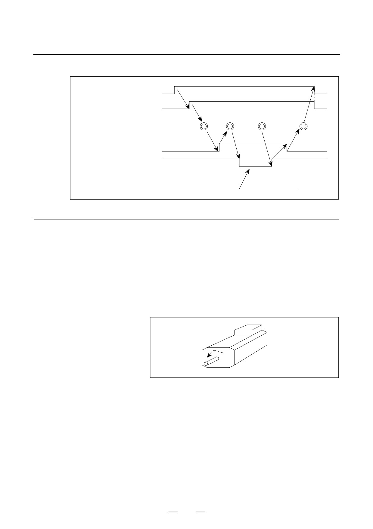
During the automatic tool change (ATC) orientation operation, in a
machine where the spindle motor is restrained by the tool unclamp
signal,there are cases where the load meter indication becomes large
and a large motor current flows by a slight slip from the orientation
stop position.
In order to prevent this, set MRDYA = 0 and release the orientation
state during tool unclamp.
If MRDYA = 1 is set at tool unclamp end, it is possible to re-enter the
orientation state.
2
Regarding the purpose of the above described 1, if the orientation
command signal remains at ORCMA = 1, even if the machine ready
signal is set to MRDYA = 0/1, there is no orientation again after 1
rotation as it only moves by the amount of the stop position slip.
388
B-65162E/03
10. INTERFACE SIGNALS
Timing chart
1
Orientation command
0
1
CRCMA
Orientation complete signal
0
ORARA
Pulling off
Attach-
Tool change operation
Tool
ment of
move
new tool
Tool catch
Detachment
OFF
Spindle unclamp
OFF
ON
0
1
Machine ready signal MRDYA
1
Excitation interception
10.2.5
Normal Rotation
D When the following four conditions hold, the spindle motor starts a
normal rotation corresponding to the speed command (positive value).
Command Signal
- Emergency stop signal *ESPA is 1
(SFRA)
- Machine ready signal MRDYA is 1
- Normal rotation command signal SFRA is 1
- Contact signal ESP is connected to 24 V (at CX4 of the PSM)
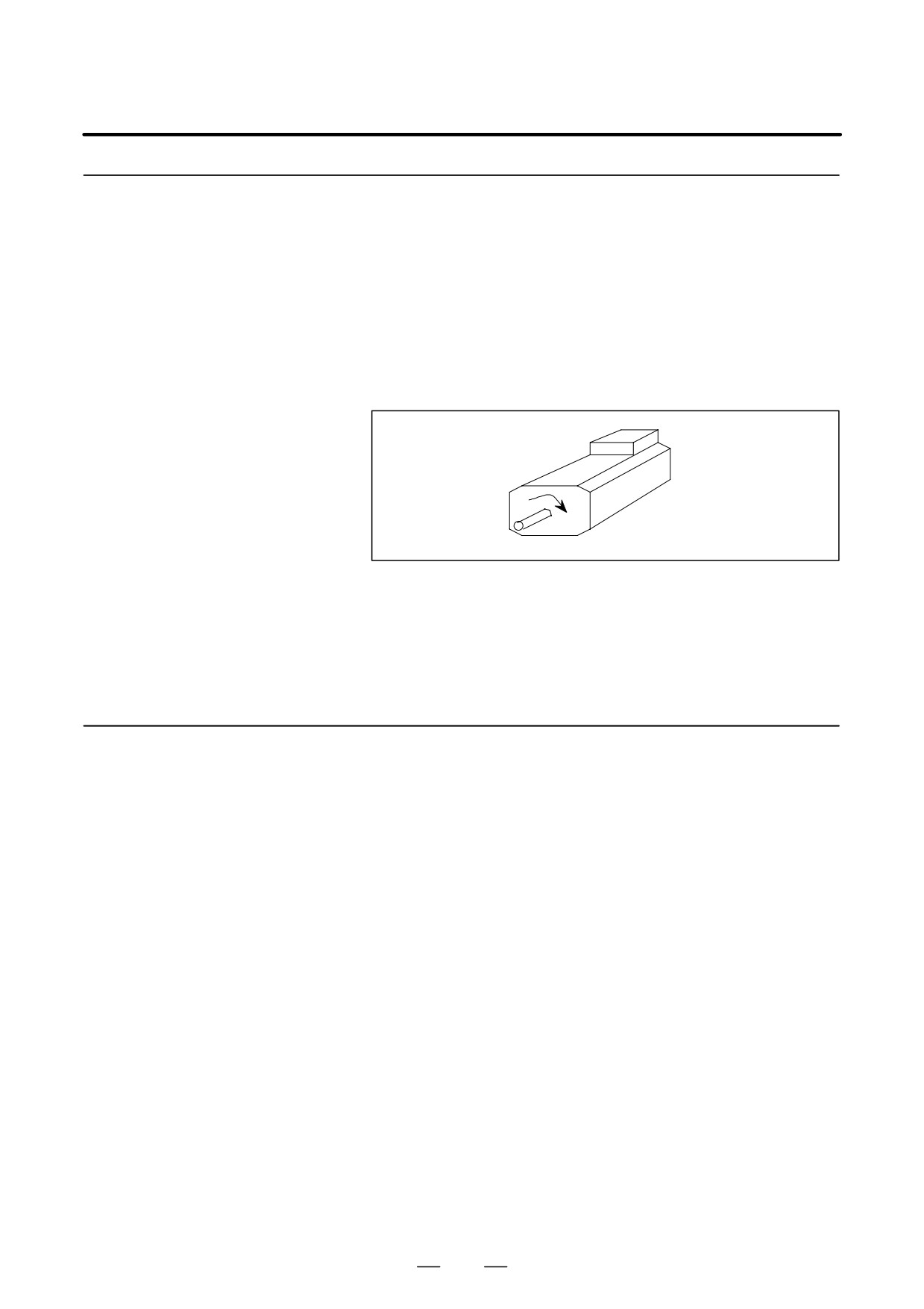
D While SFRA = 1, the spindle motor rotates in an counterclockwise
direction
(CCW) viewed from the shaft side according to the
commanded speed (positive value).
D If SFRA = 0 occurs, the spindle motor stops by the regenerative
braking. After stopping, it cuts the power supply to the spindle motor
by intercepting the transistor excitation signal.
389
10. INTERFACE SIGNALS
B-65162E/03
10.2.6
Reverse Rotation
D When the following four conditions hold, the spindle motor starts a
reverse rotation corresponding to the speed command (positive value).
Command Signal
- Emergency stop signal *ESPA is 1
(SRVA)
- Machine ready signal MRDYA is 1
- Reverse rotation command signal SRVA is 1
- Contact signal ESP is connected to 24 V (at CX4 of the PSM)
D While SRVA=1, the spindle motor rotats in a clockwise direction
(CW) looked at from the shaft side according to the speed command
(Positive value).
D If SFRA = 0 occurs, the spindle motor stops by the regenerative
braking. After stopping, it cuts the power supply to the spindle motor
by intercepting the transistor excitation signal.
D When the Normal rotation command signal (SFRA) and the reverse
rotation command signal (SRVA) are simultaneiusly ON, the spindle
motor stops.
10.2.7
Torque Limiting
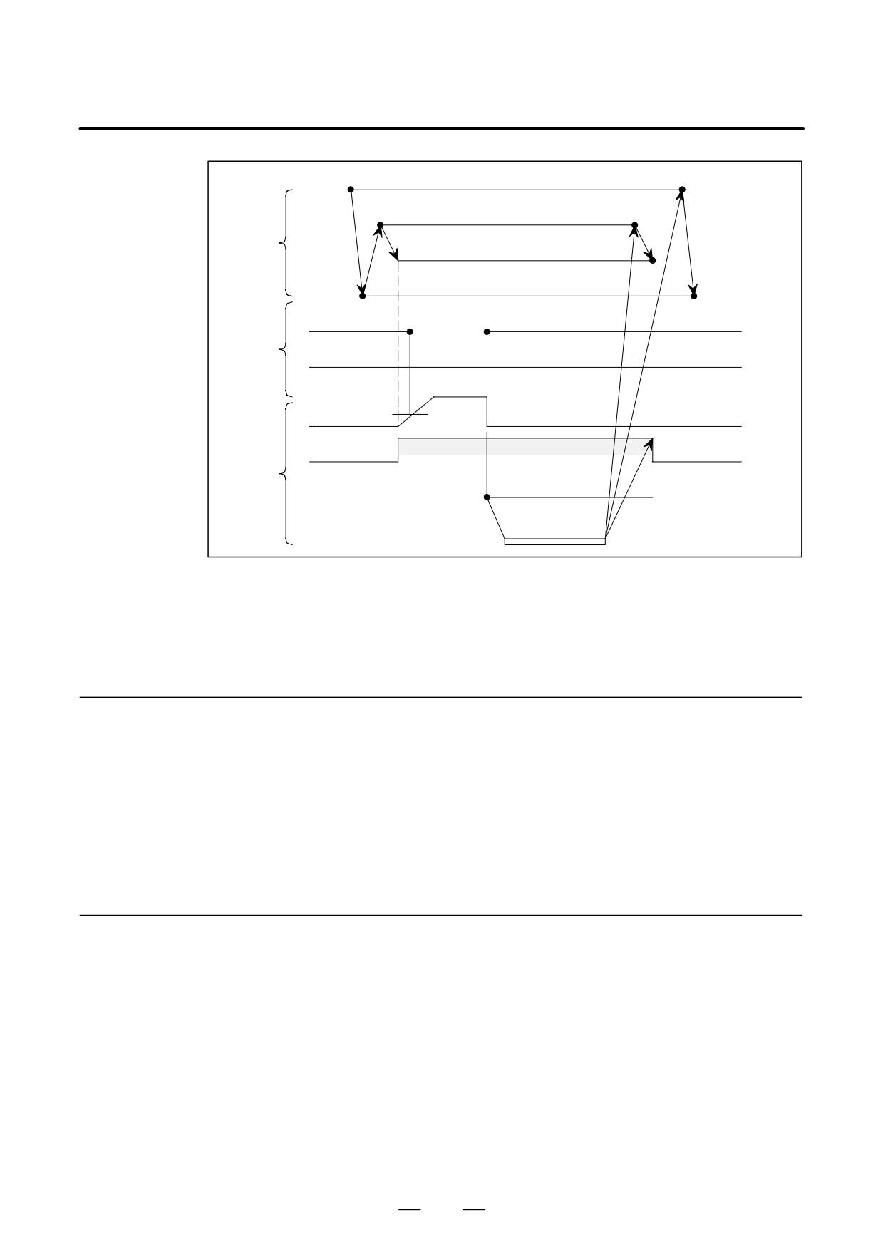
D The torque restriction (torque limit) is used in order to rotate the
spindle motor to temporarily reduce the spindle motor output torque
Command Signal
at such times as machine type spindle orientation.
(TLMLA, TLMHA)
D Set the rotation speed at orientation and the output torque at orientation
of each machine type at the machine manufacture in order to lessen
shocks even when hitting the machine stopper.
D It is possible to adjust the output torque at orientation by parameter.
D If the torque limiting command is 1, the torque limit state occurs.
Even if commanded during motor rotation it will be immediately
enabled. If the torque limit state occurs, the torque limiting signal
(TLMA) is immediately transmitted to the outside.
D At the time of performing machine type orientation at the machining
center ATC, consider the following points when designing the
magnetics cabinet sequence such that damage does not occur to the
machine stopper.
- The output torque at orientation should not be excessive.
- The rotation speed at orientation should not be excessive. For
example, when the rotation speed is excessive at the speed
detection signal, the interlock should be set such that the stopper
does not emerge.
- When the torque limit is released, the stopper should be securely
stored.
390
B-65162E/03
10. INTERFACE SIGNALS
Torque limiting command TLMLA, TLMHA
Speed command at orientation
Command
SFR / SRV
(Normal/reverse rotation command)
Torque limiting signal TLMA
Speed zero
OFF
”1”
SSTA
signal
Spindle
”0”
Speed detection
amplifier
ON within regular speed
signal
signal
Rotates slowly in torque
restriction state
Motor rota-
tion speed
(Stop)
(Stop)
(Storage)
Stopper
Projection
Machine
(Storage)
Limit switch
(Stop confirmation signal)
ATC
(Tool replacement)
ÅÅÅÅÅÅ
Example of machine type orientation sequence
When the conditions desicribed on the privious page are difficult, use the
purely electric type spindle orientation (option) which does not use a
stopper.
10.2.8
Alarm Reset Signal
D After removing the various alarm causes such as motor overheating,
excess speed deviation, short-circuiting, excess speed, excess voltage,
(ARSTA)
excess current, excess load, and voltage drop, if the alarm reset signal
is input, the alarm is released and the usable state occurs.
D Even if this signal isinputted when there is no alarm, it is disabled.
D The alarm detected by power supply module is not released.
(Such alarms reset by turning off the power.)
10.2.9
Spindle Alarm Signal
D If the state occurs in which the spindle motor operation cannot be
continuously executed, the power to the spindle motor will become
(ALMA)
OFF and the spindle motor will be stopped.
D At the same time the alarm signal ALMA = 1 occurs. Regarding the
alarm contents, confirm by the display section of the spindle amplifier.
D Set the command signal to the spindle amplifier (speed command,
forward/reverse rotation command, torgue limit command, spindle
orientation command ) in the reset state using the alarm signal output.
If it is not in the reset state (state that signal from PMC is all clear),
when the alarm on the spindle amplifier is released there is a danger
that the spindle motor may rotate.
391
10. INTERFACE SIGNALS
B-65162E/03
D Because the spindle motor enters the power OFF, coasting operates at
the same time as the alarm signal is output, it is necessary to set in an
emergency stop state and to set the feedhold state at the CNC or
magnetics cabinet side.
D When the alarm state has occurred, ALMA = 1 occurs.
While the alarm signal is 1, the spindle motor enters coasting operates
state regardless of any command from the outside.
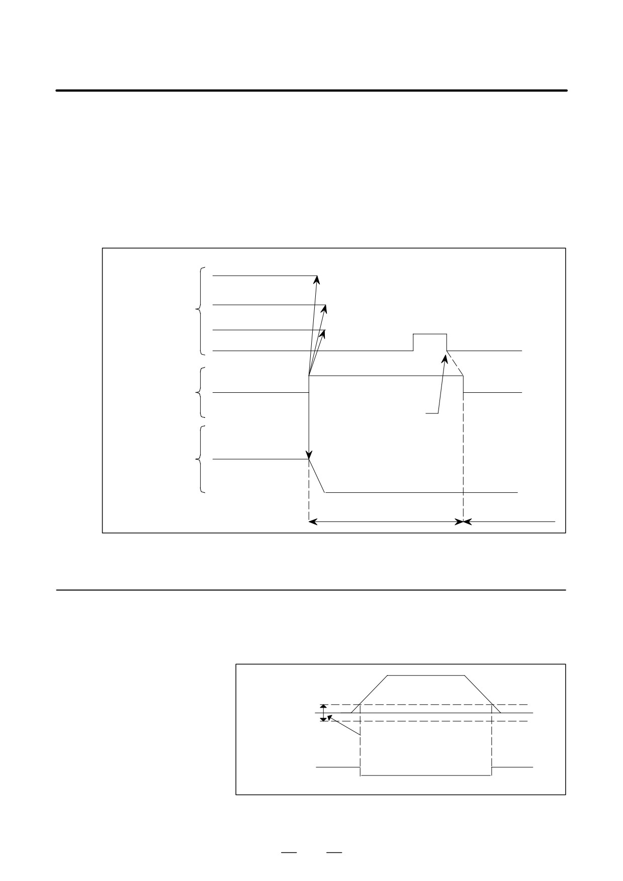
D The relationship between the alarm signal and the alarm reset signal
is as shown in Fig. 10.2.9.
Speed command
Forward rotation/back
rotation command
SFRA (SRVA)
Spindle control
Spindle orientatin
input signal
1
commandORCMA
0
0
ARSTA
(Alarm reset)
1
0
Spindle control
ALMA
output signal
(Alarm)
Remove the alarm cause
Motor rotation speed
Motor operation
(Stop)
Does not operate even
Usable state
when there is a command
Fig.10.2.9 Timing Chart of the Spindle Alarm Signal
10.2.10
Zero-speed Detecting
D If the actual rotation speed of the spindle motor is reduced to be lower
than the zero-speed detection point for the stop command, SSTA = 1
Signal (SSTA)
occurs.
Motor
0
speed
Zero-speed detection point
("0.75%of maximum speed
as the standard)
SSTA (1)
(1)
(0)
Fig.10.2.10 Signal Indicating that the spindlespeed dropped
to close to zero
392