FANUC SERVO AMPLIFIER a series. DESCRIPTIONS (B-65162E/03) - page 12
B-65162E/03
9.CONNECTION
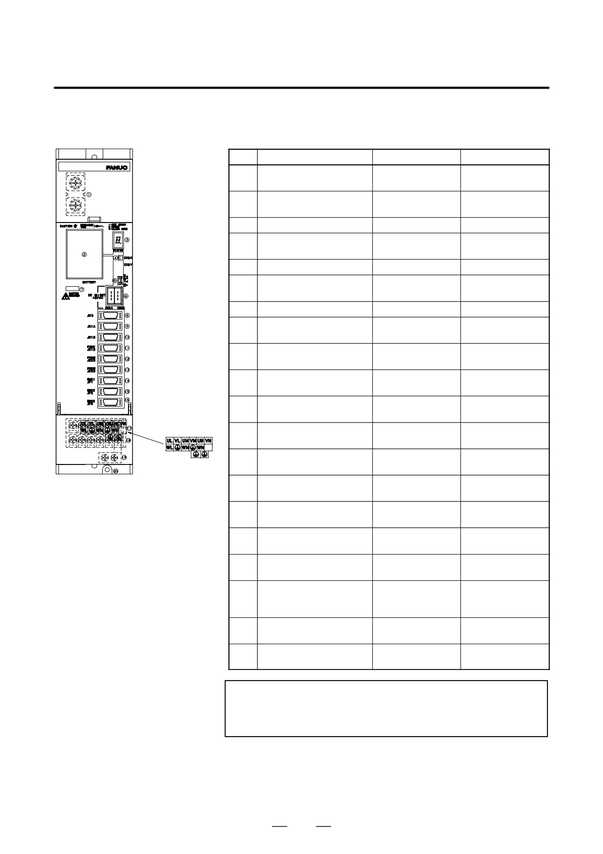
(g)-2
TYPE B
Table.9.3.2 (g) Names of connectors and terminal blocks
Names
Display
Remarks
1
DC link terminal block
Display the terminal
block TB1
2
Battery for ABS pulse cod-
BATTERY
A06B-6073-K001
er
3
Status LED
STATUS
4
Power connector for ABS
CX5X
Both connectors
pulse coder battery
have same function.
5
Fuse for 24V power
F2
3.2A, 48VDC
6
24V power I/O connector
CX2A/CX2B
Both connectors
have same function.
7
DC link charge LED
(Warning)
8
Signal check connector
JX5
Use an SVM check
board.
9
Input connector for inter-
JX1A
face between modules
10
Output connector for inter-
JX1B
face between modules
11
NC interface connector : L
PWM1/JS1B
axis for type-B interface
12
NC interface connector : M
PWM2/JS2B
axis for type-B interface
13
NC interface connector : N
PWM3/JS3B
axis for type-B interface
14
Pulse coder connector : L
ENC1/JF1
axis
15
Pulse coder connector : M
ENC2/JF2
axis
16
Pulse coder connector : N
ENC3/JF3
axis
17
Terminal block for motor
power line
18
Terminal names for termi-
Display the terminal
nal block for motor power
block TB2
line
19
Earth plate
Attatched to amplifi-
er
20
Tapped hole for grounding
the flange
WARNING
Do not touch module components or connected cables
while this LED is lit. There is a danger of electric shock.
333
9. CONNECTION
B-65162E/03
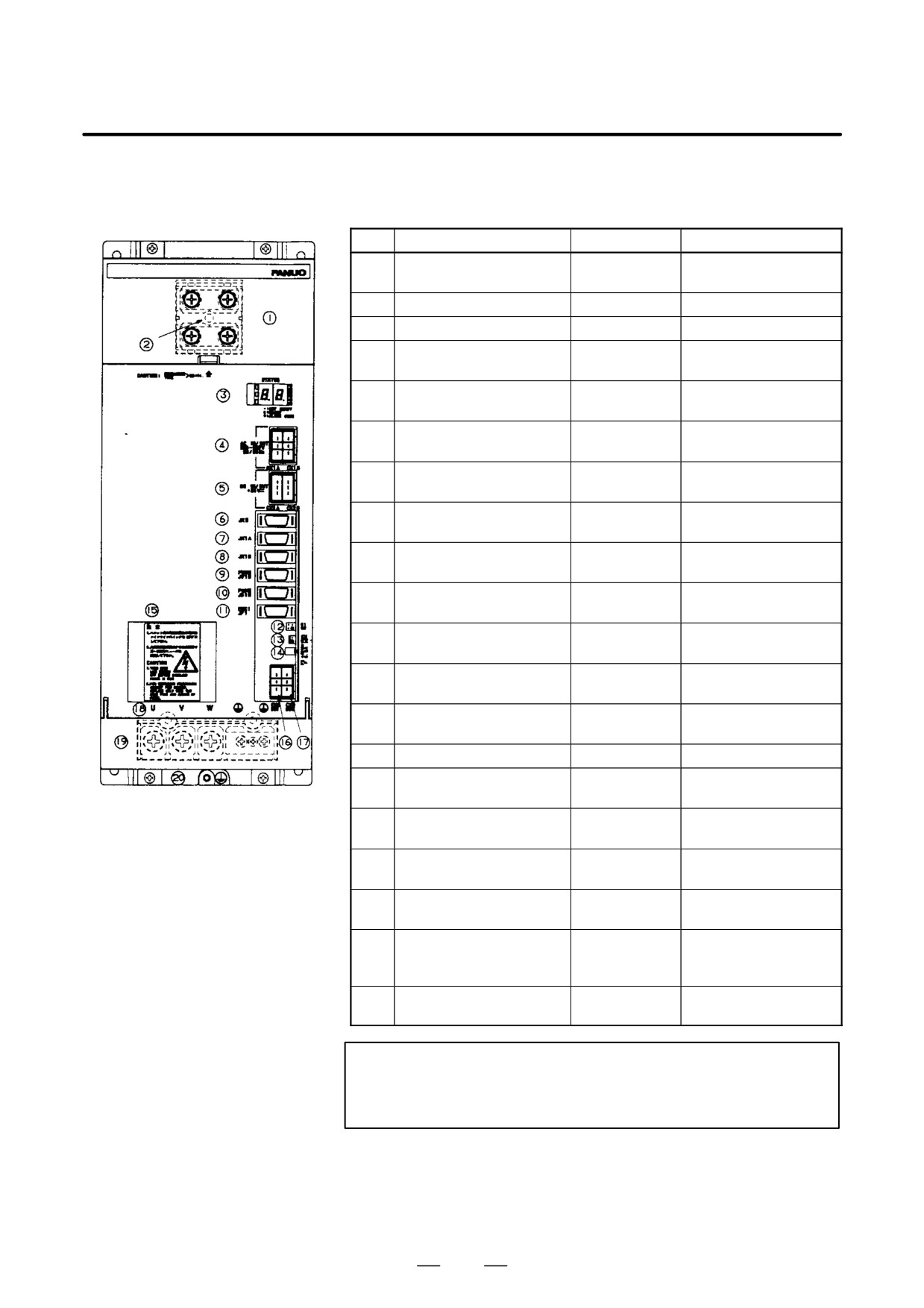
(h)-2
SVM1-240 SVM1-360
Table.9.3.2 (h) Names of connectors and terminal blocks
Names
Display
Remarks
1
DC link terminal block
Display the terminal
block TB1
2
DC link charge LED
(Warning)
3
Status LED
STATUS
4
24VDC power I/O connec-
CX1A/CX1B
tor
5
24V power I/O connector
CX2A/CX2B
Both connectors have
same function.
6
Signal check connector
JX5
Use an SVM check
board.
7
Input connector for inter-
JX1A
face between modules
8
Output connector for inter-
JX1B
face between modules
9
CNC interface connector
PWM11/JV1B
TYPE A interface
10
CNC interface connector
PWM11/JS1B
TYPE B interface
11
Pulse coder connector
JF1
For TYPE B interface
only
12
Interface changeover con-
S1
TYPE A Interface : S1
nector
S2
TYPE B Interface : S2
13
Power connector for ABS
CX5X
pulse coder battery
14
Fuse for 24V power
15
Battery for ABS pulse cod-
BATTERY
A06B-6073-K001
er
16
Dynamic brake interface
CX8
connector
17
Dynamic brake drive coil
CX9
connector
18
Terminal block for motor
power line
19
Terminal names for termi-
Display the terminal
nal block for motor power
block TB2
line
20
Tapped hole for grounding
the flange
WARNING
Do not touch module components or connected cables
while this LED is lit. There is a danger of electric shock.
334
B-65162E/03
9.CONNECTION
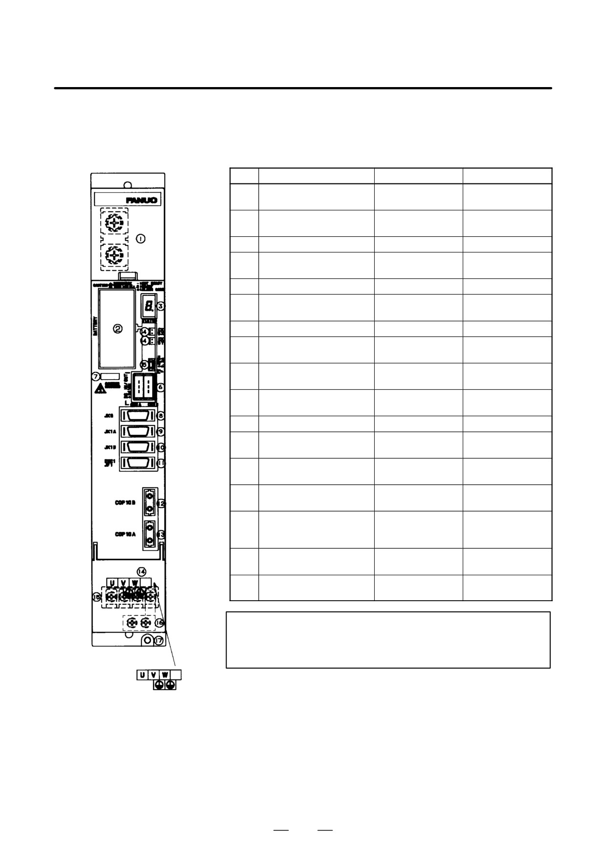
2.
FSSB Interface
(a)
SVM1-12, SVM1-20, SVM1-40S,
SVM1-40L, SVM1-80
Table.9.3.2 (i) Names of connectors and terminal blocks
Names
Display
Remarks
1
DC link terminal block
Display the terminal
block TB1
2
Battery for ABS pulse cod-
BATTERY
A06B-6073-K001
er
3
Status LED
STATUS
4
Power connector for ABS
CX5X
Both connectors
pulse coder battery
CX5Y
have same function.
5
Fuse for 24V power
F2
3.2A, 48VDC
6
24V power I/O connector
CX2A
Both connectors
CX2B
have same function.
7
DC link charge LED
(Warning)
8
Signal check connector
JX5
Use an SVM check
board.
9
Input connector for inter-
JX1A
face between modules
10
Output connector for inter-
JX1B
face between modules
11
Pulse coder connector
ENC1/JF1
12
FSSB optical input connec-
COP10B
tor
13
FSSB optical output con-
COP10A
nector
14
Terminal block for motor
power line
15
Terminal names for termi-
Display the terminal
nal block for motor power
block TB2
line
16
Earth plate
Attatched to amplifi-
er
17
Tapped hole for grounding
the flange
WARNING
Do not touch module components or connected cables
while this LED is lit. There is a danger of electric shock.
335
9. CONNECTION
B-65162E/03
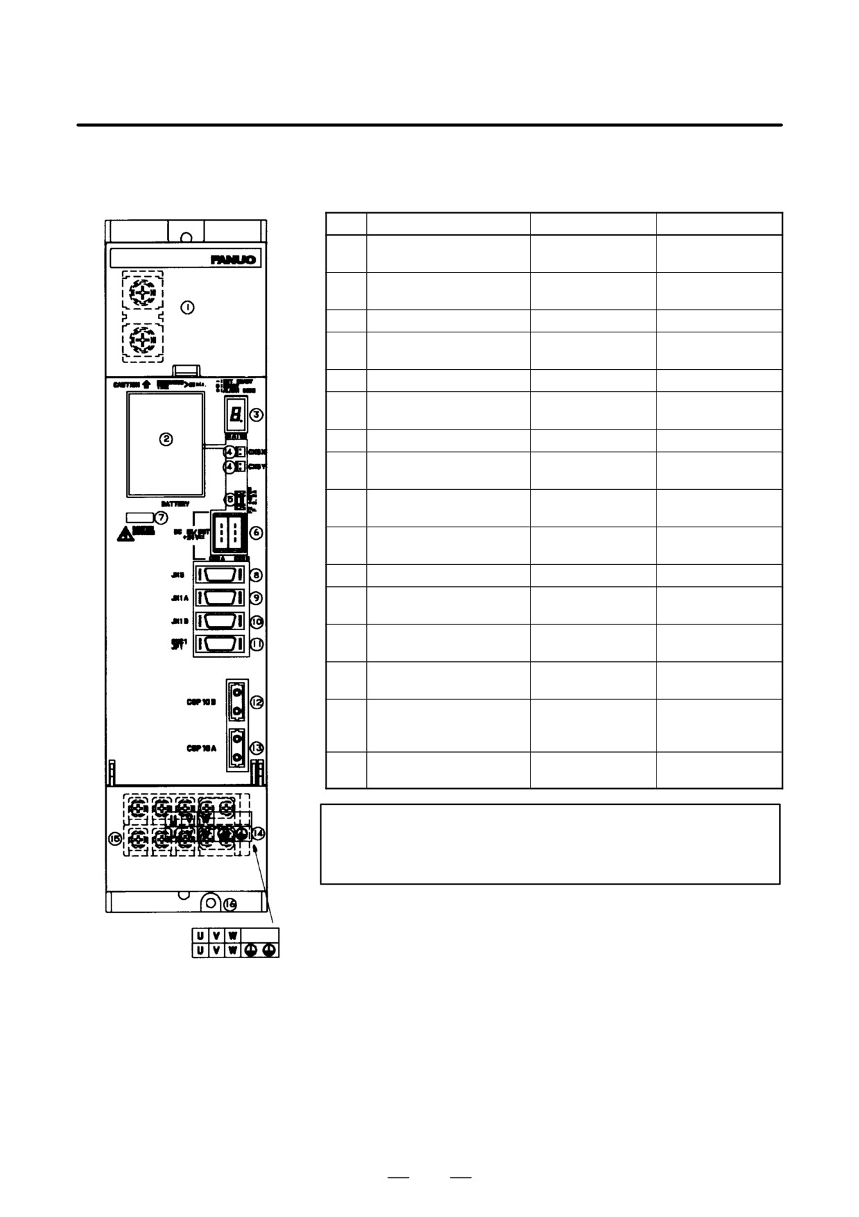
(b)
SVM1-130
Table.9.3.2 (j) Names of connectors and terminal blocks
Names
Display
Remarks
1
DC link terminal block
Display the terminal
block TB1
2
Battery for ABS pulse cod-
BATTERY
A06B-6073-K001
er
3
Status LED
STATUS
4
Power connector for ABS
CX5X
Both connectors
pulse coder battery
CX5Y
have same function.
5
Fuse for 24V power
F2
3.2A, 48VDC
6
24V power I/O connector
CX2A
Both connectors
CX2B
have same function.
7
DC link charge LED
(Warning)
8
Signal check connector
JX5
Use an SVM check
board.
9
Input connector for inter-
JX1A
face between modules
10
Output connector for inter-
JX1B
face between modules
11
Pulse coder connector
ENC1/JF1
12
FSSB optical input connec-
COP10B
tor
13
FSSB optical output con-
COP10A
nector
14
Terminal block for motor
power line
15
Terminal names for termi-
Display the terminal
nal block for motor power
block TB2
line
16
Tapped hole for grounding
the flange
WARNING
Do not touch module components or connected cables
while this LED is lit. There is a danger of electric shock.
336
B-65162E/03
9.CONNECTION
(c)
SVM1-20HV, SVM1-40HV,
SVM1-60HV
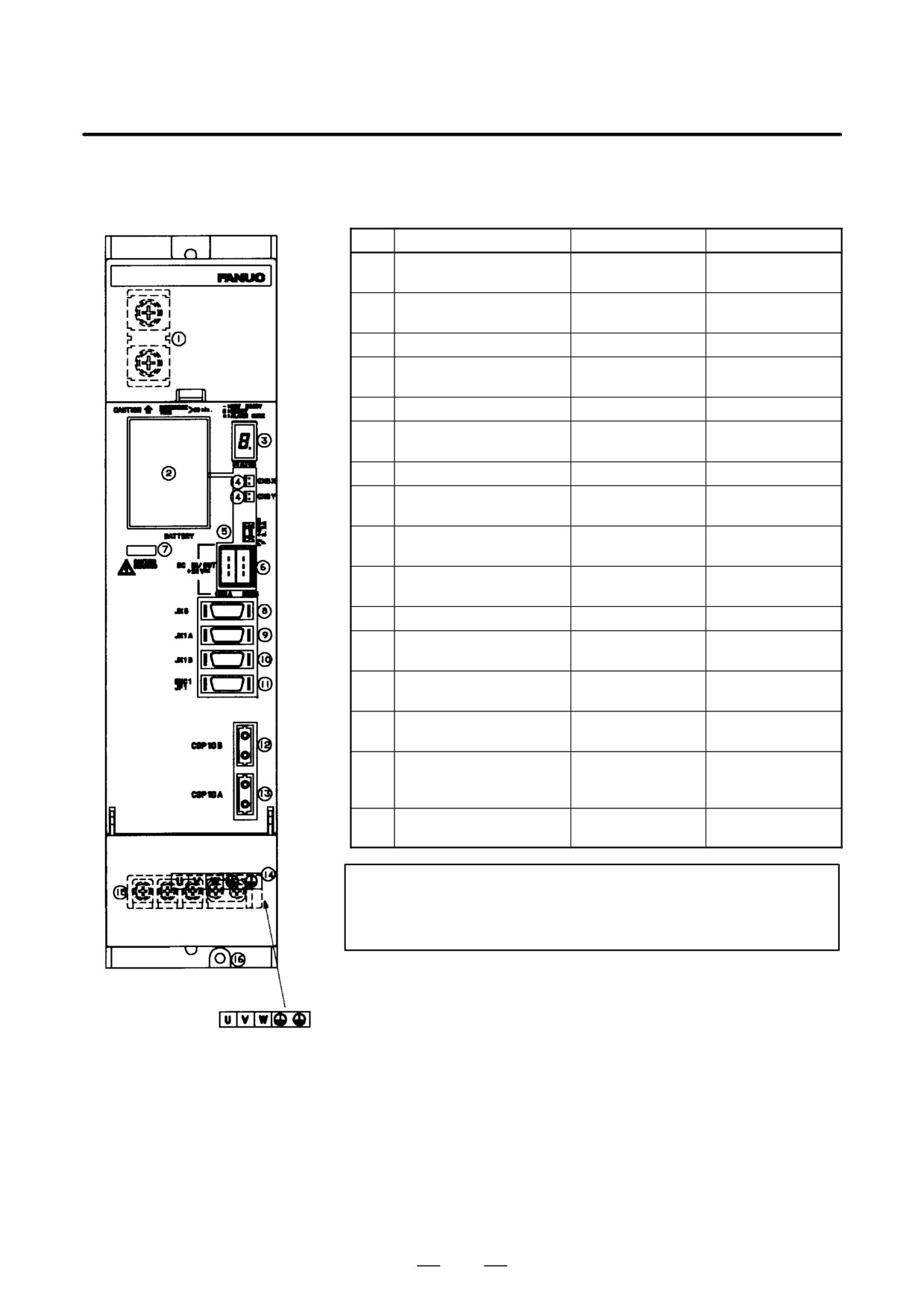
Table.9.3.2 (k) Names of connectors and terminal blocks
Names
Display
Remarks
1
DC link terminal block
Display the terminal
block TB1
2
Battery for ABS pulse cod-
BATTERY
A06B-6073-K001
er
3
Status LED
STATUS
4
Power connector for ABS
CX5X
Both connectors
pulse coder battery
CX5Y
have same function.
5
Fuse for 24V power
F2
3.2A, 48VDC
6
24V power I/O connector
CX2A
Both connectors
CX2B
have same function.
7
DC link charge LED
(Warning)
8
Signal check connector
JX5
Use an SVM check
board.
9
Input connector for inter-
JX1A
face between modules
10
Output connector for inter-
JX1B
face between modules
11
Pulse coder connector
ENC1/JF1
12
FSSB optical input connec-
COP10B
tor
13
FSSB optical output con-
COP10A
nector
14
Terminal block for motor
power line
15
Terminal names for termi-
Display the terminal
nal block for motor power
block TB2
line
16
Tapped hole for grounding
the flange
WARNING
Do not touch module components or connected cables
while this LED is lit. There is a danger of electric shock.
337
9. CONNECTION
B-65162E/03
(d)
SVM2-12/12, SVM2-12/20,
SVM2-20/20, SVM2-12/40,
SVM2-20/40, SVM2-40/40
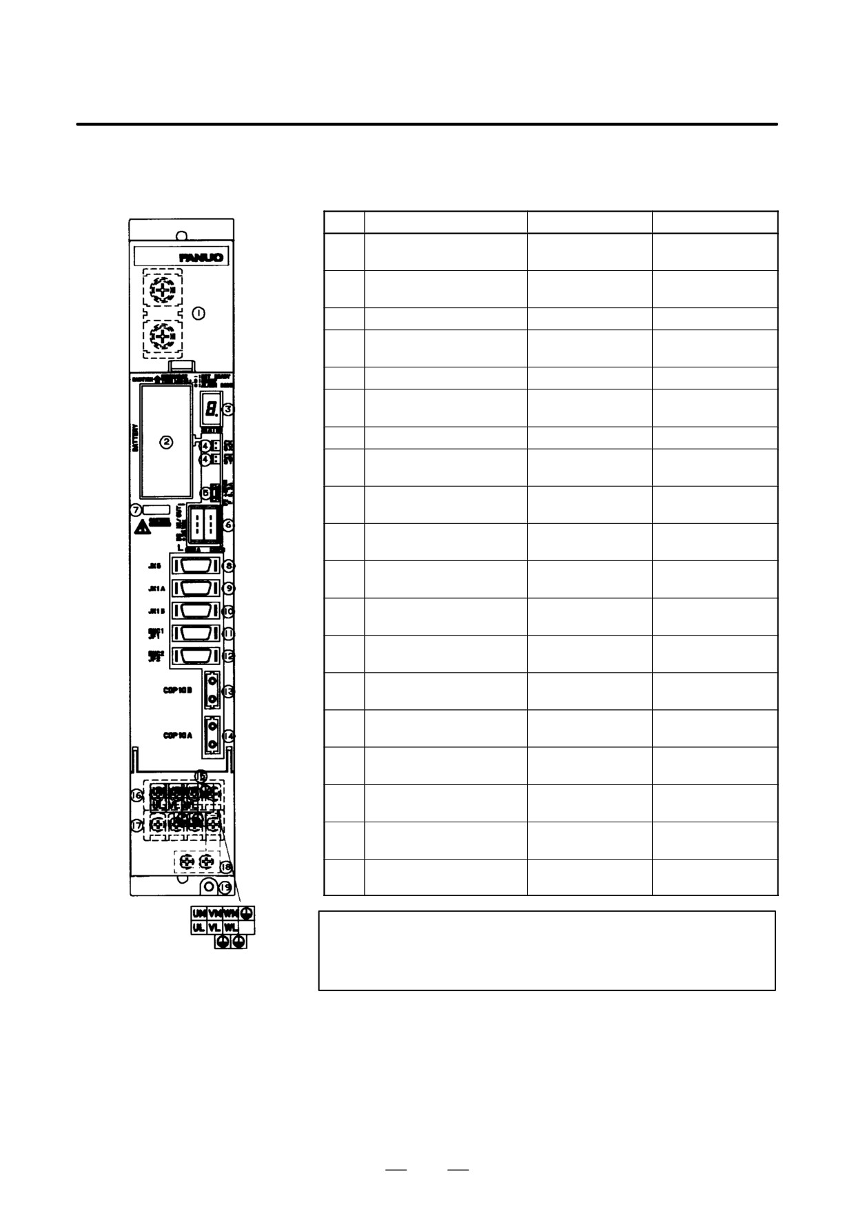
Table.9.3.2 (l) Names of connectors and terminal blocks
Names
Display
Remarks
1
DC link terminal block
Display the terminal
block TB1
2
Battery for ABS pulse cod-
BATTERY
A06B-6073-K001
er
3
Status LED
STATUS
4
Power connector for ABS
CX5X
Both connectors
pulse coder battery
CX5Y
have same function.
5
Fuse for 24V power
F2
3.2A, 48VDC
6
24V power I/O connector
CX2A/CX2B
Both connectors
have same function.
7
DC link charge LED
(Warning)
8
Signal check connector
JX5
Use an SVM check
board.
9
Input connector for inter-
JX1A
face between modules
10
Output connector for inter-
JX1B
face between modules
11
Pulse coder connector for
ENC1/JF1
the L-axis
12
Pulse coder connector for
ENC2/JF2
the M-axis
13
FSSB optical input connec-
COP10B
tor
14
FSSB optical output con-
COP10A
nector
15
Terminal block for motor
power line
16
Motor power line terminal
Display the terminal
board for the M-axis
block TB2
17
Motor power line terminal
Display the terminal
board for the L-axis
block TB2
18
Earth plate
Attatched to amplifi-
er
19
Tapped hole for grounding
the flange
WARNING
Do not touch module components or connected cables
while this LED is lit. There is a danger of electric shock.
338
B-65162E/03
9.CONNECTION
(e)
SVM2-12/12, SVM2-12/20,
SVM2-20/20, SVM2-12/40,
SVM2-20/40, SVM2-40/40
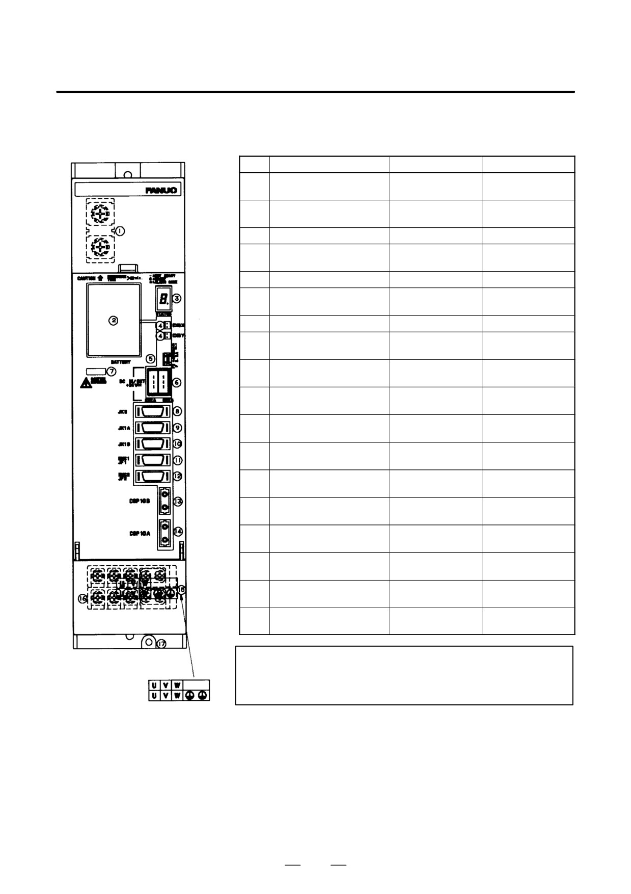
Table.9.3.2 (m) Names of connectors and terminal blocks
Names
Display
Remarks
1
DC link terminal block
Display the terminal
block TB1
2
Battery for ABS pulse cod-
BATTERY
A06B-6073-K001
er
3
Status LED
STATUS
4
Power connector for ABS
CX5X/CX5Y
Both connectors
pulse coder battery
have same function.
5
Fuse for 24V power
F2
3.2A, 48VDC
6
24V power I/O connector
CX2A/CX2B
Both connectors
have same function.
7
DC link charge LED
(Warning)
8
Signal check connector
JX5
Use an SVM check
board.
9
Input connector for inter-
JX1A
face between modules
10
Output connector for inter-
JX1B
face between modules
11
Pulse coder connector for
ENC1/JF1
the L-axis
12
Pulse coder connector for
ENC2/JF2
the M-axis
13
FSSB optical input connec-
COP10B
tor
14
FSSB optical output con-
COP10A
nector
15
Terminal block for motor
power line
16
Motor power line terminal
Display the terminal
board for the M-axis
block TB2
17
Motor power line terminal
Display the terminal
board for the L-axis
block TB2
18
Tapped hole for grounding
the flange
WARNING
Do not touch module components or connected cables
while this LED is lit. There is a danger of electric shock.
339
9. CONNECTION
B-65162E/03
(f)
SVM3-12/12/12, SVM3-12/12/20,
SVM3-12/20/20, SVM3-20/20/20,
SVM3-12/12/40, SVM3-12/20/40,
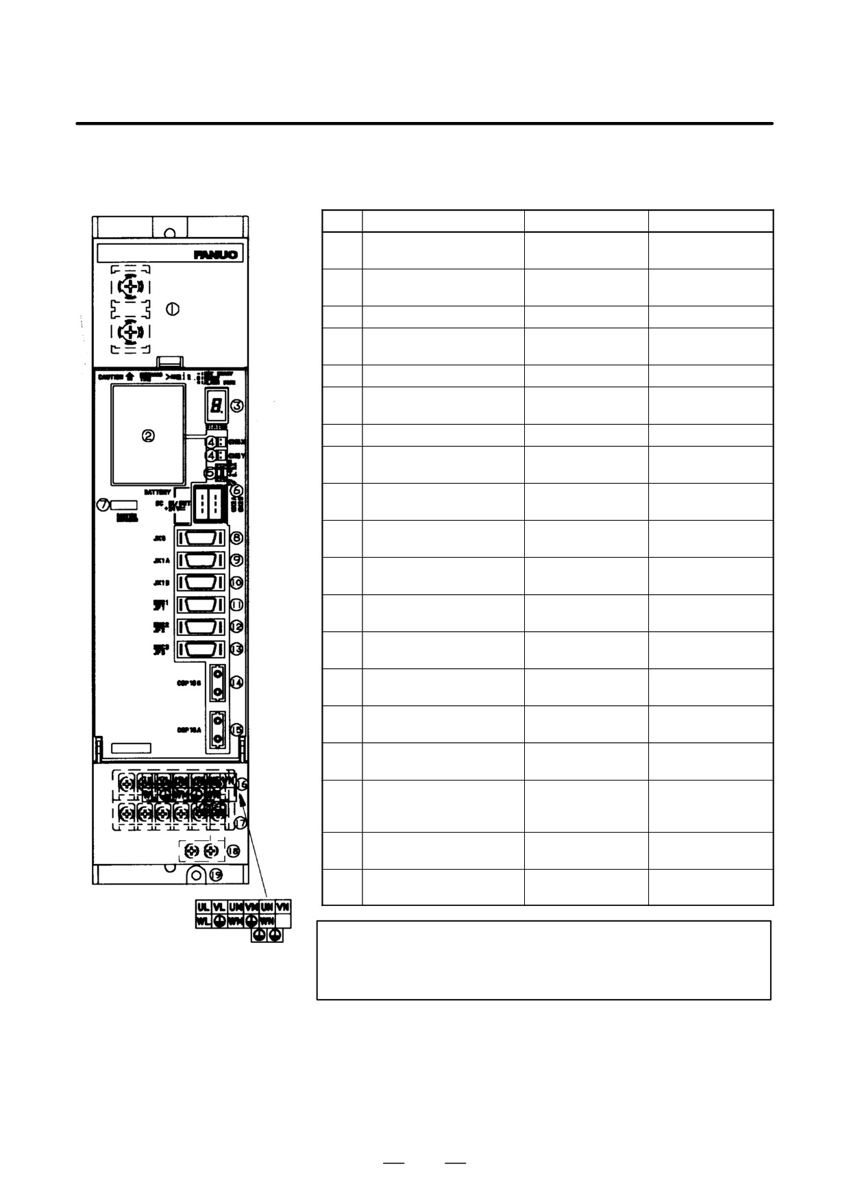
Table.9.3.2 (n) Names of connectors and terminal blocks
SVM3-20/20/40
Names
Display
Remarks
1
DC link terminal block
Display the terminal
block TB1
2
Battery for ABS pulse cod-
BATTERY
A06B-6073-K001
er
3
Status LED
STATUS
4
Power connector for ABS
CX5X
Both connectors
pulse coder battery
CX5Y
have same function.
5
Fuse for 24V power
F2
3.2A, 48VDC
6
24V power I/O connector
CX2A/CX2B
Both connectors
have same function.
7
DC link charge LED
(Warning)
8
Signal check connector
JX5
Use an SVM check
board.
9
Input connector for inter-
JX1A
face between modules
10
Output connector for inter-
JX1B
face between modules
11
Pulse coder connector for
ENC1/JF1
the L-axis
12
Pulse coder connector for
ENC2/JF2
the M-axis
13
Pulse coder connector for
ENC3/JF3
the N-axis
14
FSSB optical input connec-
COP10B
tor
15
FSSB optical output con-
COP10A
nector
16
Terminal block for motor
power line
17
Terminal names for termi-
Display the terminal
nal block for motor power
block TB2
line
18
Earth plate
Attatched to amplifi-
er
19
Tapped hole for grounding
the flange
WARNING
Do not touch module components or connected cables
while this LED is lit. There is a danger of electric shock.
340
B-65162E/03
9.CONNECTION
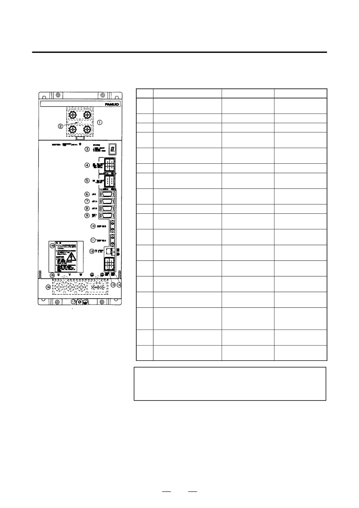
(g)
SVM1-240, SVM1-360
Table.9.3.2 (o) Names of connectors and terminal blocks
Names
Display
Remarks
1
DC link terminal block
Display the terminal
block TB1
2
DC link charge LED
(Warning)
3
Status LED
STATUS
4
200 VAC power input/out-
CX1A/CX1B
put connector
5
24 VDC power input/output
CX2A/CX2B
Both connectors
connector
have same function.
6
Signal check connector
JX5
7
Input connector for inter-
JX1A
face between modules
8
Output connector for inter-
JX1B
face between modules
9
Pulse coder connector
JF1
10
FSSB optical input connec-
COP10B
tor
11
FSSB optical output con-
COP10A
nector
12
Power connector for ABS
CX5X
pulse coder battery
CX5Y
13
Dynamic brake interface
CX8
connector
14
Dynamic brake drive coil
CX9
connector
15
Terminal block for motor
power line
16
Terminal names for termi-
Display the terminal
nal block for motor power
block TB2
line
17
Tapped hole for grounding
the flange
18
Battery for ABS pulse cod-
er
WARNING
Do not touch module components or connected cables
while this LED is lit. There is a danger of electric shock.
341
9. CONNECTION
B-65162E/03
9.3.3
Spindle Amplifier
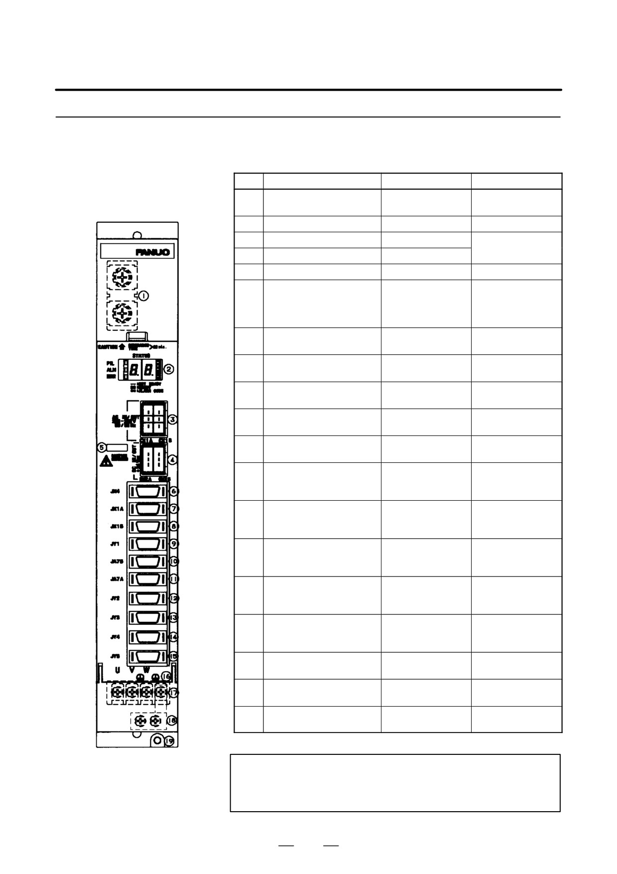
Table.9.3.3 (a) Names of connectors and terminal blocks
Module
Names
Display
Remarks
(a)
SPM-2.2
1
DC link terminal block
Display the terminal
block TB1
2
Status LED
STATUS
3
200VAC I/O connector
CX1A/CX1B
Both connectors
have same function
4
24 VDC connector
CX2A/CX2B
5
DC link charge LED
(Warning)
6
Connector for signal check,
JX4
Use an SPM check
pulse generator signal out-
board.
put, and position coder sig-
nal output
7
Output connector for inter-
JX1A
face between modules
8
Input connector for inter-
JX1B
face between modules
9
Connector for load meter
JY1
and speedometer
10
Input connector for electric
JA7B
serial interface
11
Output connector for elec-
JA7A
tric serial interface
12
Connector for pulse gener-
JY2
ator, built-in sensor, and
Cs axis sensor for motor
13
Connector for magnetic
JY3
sensor and external single
rotation signal
14
Connector for position cod-
JY4
er and high-resolution
position coder
15
Connector for Cs-axis sen-
JY5
TYPE 2, 4
sor for spindle and built-in
Cs-axis sensor
16
Terminal names for termi-
nal block for motor power
line
17
Terminal block for motor
TB2
Display the terminal
power line
block TB2
18
Earth plate
Attatched to amplifi-
er
19
Tapped hole for grounding
the flange
WARNING
Do not touch module components or connected cables
while this LED is lit. There is a danger of electric shock.
342
B-65162E/03
9.CONNECTION
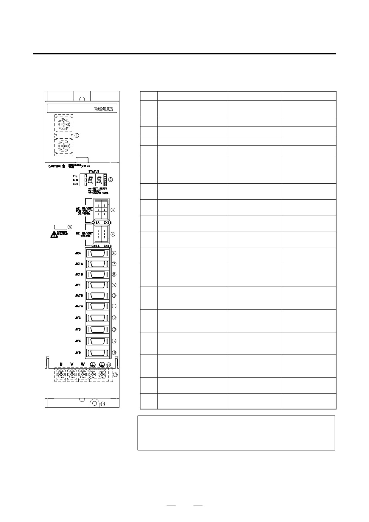
(b)
SPM-5.5, SPM-11, SPM-11HV
(TYPE 1, 2, 4)
Table.9.3.3 (b) Names of connectors and terminal blocks
Name
Display
Remarks
1
DC link terminal block
Display the terminal
block TB1
2
Status LED
STATUS
3
200VAC I/O connector
CX1A/CX1B
Both connectors
have same function
4
24 VDC connector
CX2A/CX2B
5
DC link charge LED
(Warning)
6
Connector for signal check,
JX4
Use an SPM check
pulse generator signal out-
board.
put, and position coder sig-
nal output
7
Output connector for inter-
JX1A
face between modules
8
Input connector for inter-
JX1B
face between modules
9
Connector for load meter
JY1
and speedometer
10
Input connector for electric
JA7B
serial interface
11
Output connector for elec-
JA7A
tric serial interface
12
Connector for pulse gener-
JY2
ator, built-in sensor, and
Cs axis sensor for motor
13
Connector for magnetic
JY3
sensor and external single
rotation signal
14
Connector for position cod-
JY4
er and high-resolution
position coder
15
Connector for Cs-axis sen-
JY5
Only for TYPE II
sor for spindle and built-in
Cs-axis sensor
16
Terminal names for termi-
nal block for motor power
line
17
Terminal block for motor
Display the terminal
power line
block TB2
18
Tapped hole for grounding
the flange
WARNING
Do not touch module components or connected cables
while this LED is lit. There is a danger of electric shock.
343
9. CONNECTION
B-65162E/03
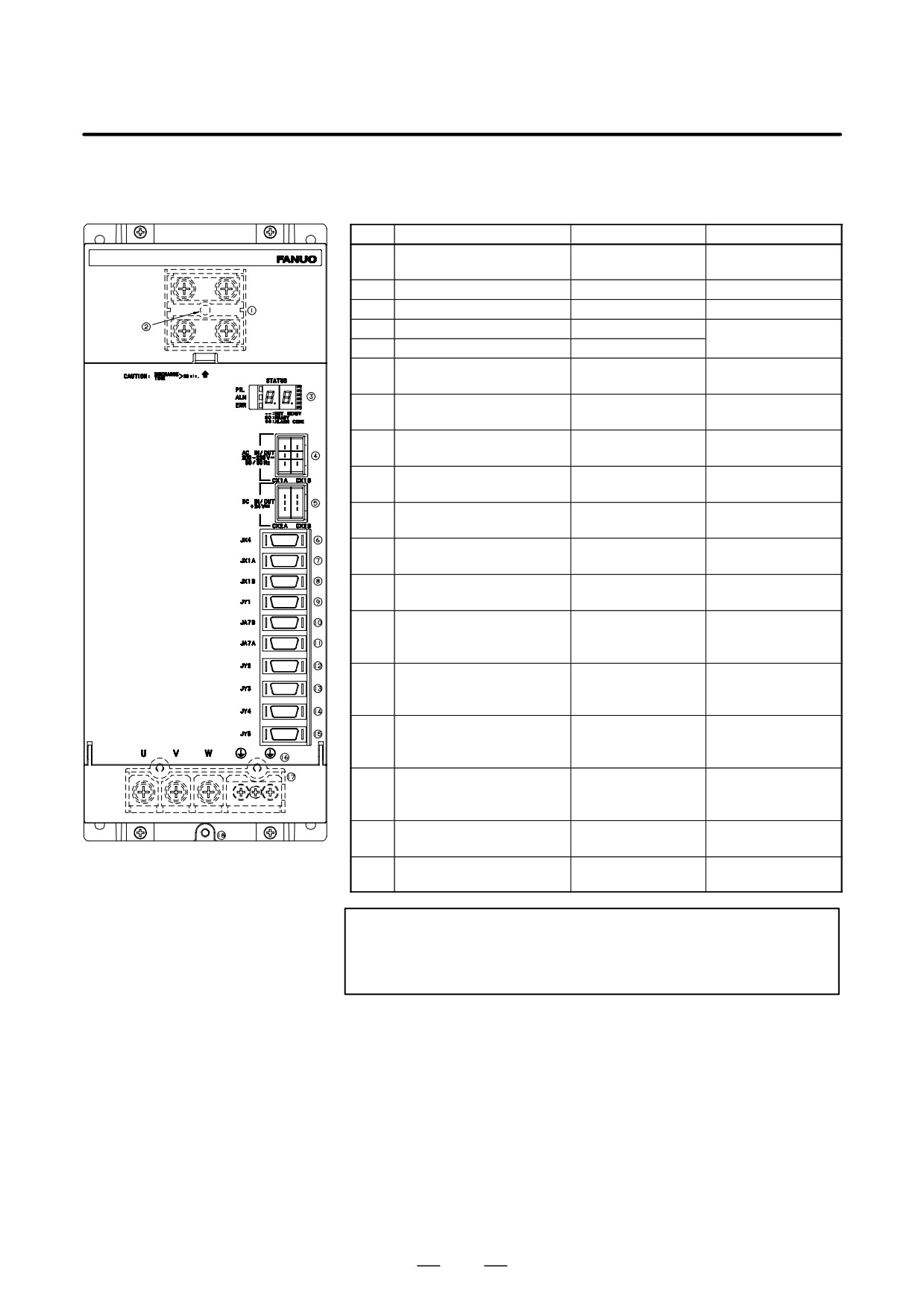
(c)
SPM-15, 22, 26, 30, SPM-15HV,
26HV, 45HV (TYPE 1, 2, 4)
Table.9.3.3 (c) Names of connectors and terminal blocks
Names
Display
Remarks
1
DC link terminal block
Display the terminal
block TB1
2
DC link charge LED
(Warning)
3
Status LED
STATUS
4
200VAC I/O connector
CX1A/CX1B
Both connectors
5
24 VDC I/O connector
CX2A/CX2B
have same
function.
6
Signal check connector
JX4
Use an SPM check
board.
7
Output connector for inter-
JX1A
face between modules
8
Input connector for inter-
JX1B
face between modules
9
Connector for load meter
JY1
and speedometer
10
Input connector for electric
JA7B
serial interface
11
Output connector for elec-
JA7A
tric serial interface
12
Connector for pulse gener-
JY2
ator, built-in sensor
13
Connector for magnetic
JY3
sensor and external single
rotation signal
14
Connector for position cod-
JY4
er and high-resolution
position coder
15
Connector for Cs-axis sen-
JY5
Only for TYPE 2, 4
sor for spindle and built-in
Cs-axis sensor
16
Terminal names for termi-
nal block for motor power
line
17
Terminal block for motor
Display the terminal
power line
block TB2
18
Tapped hole for grounding
the flange
WARNING
Do not touch module components or connected cables
while this LED is lit. There is a danger of electric shock.
344
B-65162E/03
9.CONNECTION
(d)
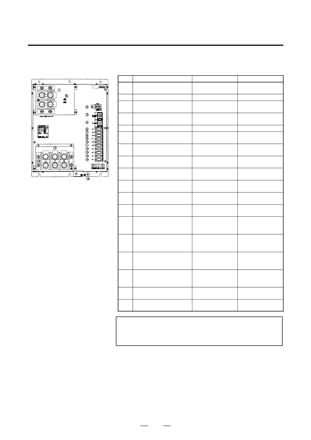
SPM-45, SPM-75HV, (TYPE 1, 2, 4)
Table.9.3.3 (d) Names of connectors and terminal blocks
Names
Display
Remarks
1
DC link terminal block
Display the terminal
block TB1
2
Status LED
STATUS
3
200VAC I/O connector
CX1A/CX1B
Both connectors
have same function.
4
24 VDC I/O connector
CX2A/CX2B
Both connectors
have same function.
5
DC link charge LED
(Warning)
6
Signal check connector
JX4
Use an SPM check
board.
7
Output connector for inter-
JX1A
face between modules
8
Input connector for inter-
JX1B
face between modules
9
Connector for load meter
JY1
and speedometer
10
Input connector for electric
JA7B
serial interface
11
Output connector for elec-
JA7A
tric serial interface
12
Connector for pulse gener-
JY2
ator, built-in sensor
13
Connector for magnetic
JY3
sensor and external single
rotation signal
14
Connector for position cod-
JY4
er and high-resolution
position coder
15
Connector for Cs-axis sen-
JY5
Only for TYPE 2, 4
sor for spindle and built-in
Cs-axis sensor
16
Terminal names for termi-
nal block for motor power
line
17
Terminal block for motor
Display the terminal
power line
block TB2
18
Tapped hole for grounding
the flange
WARNING
Do not touch module components or connected cables
while this LED is lit. There is a danger of electric shock.
345
9. CONNECTION
B-65162E/03
(e)
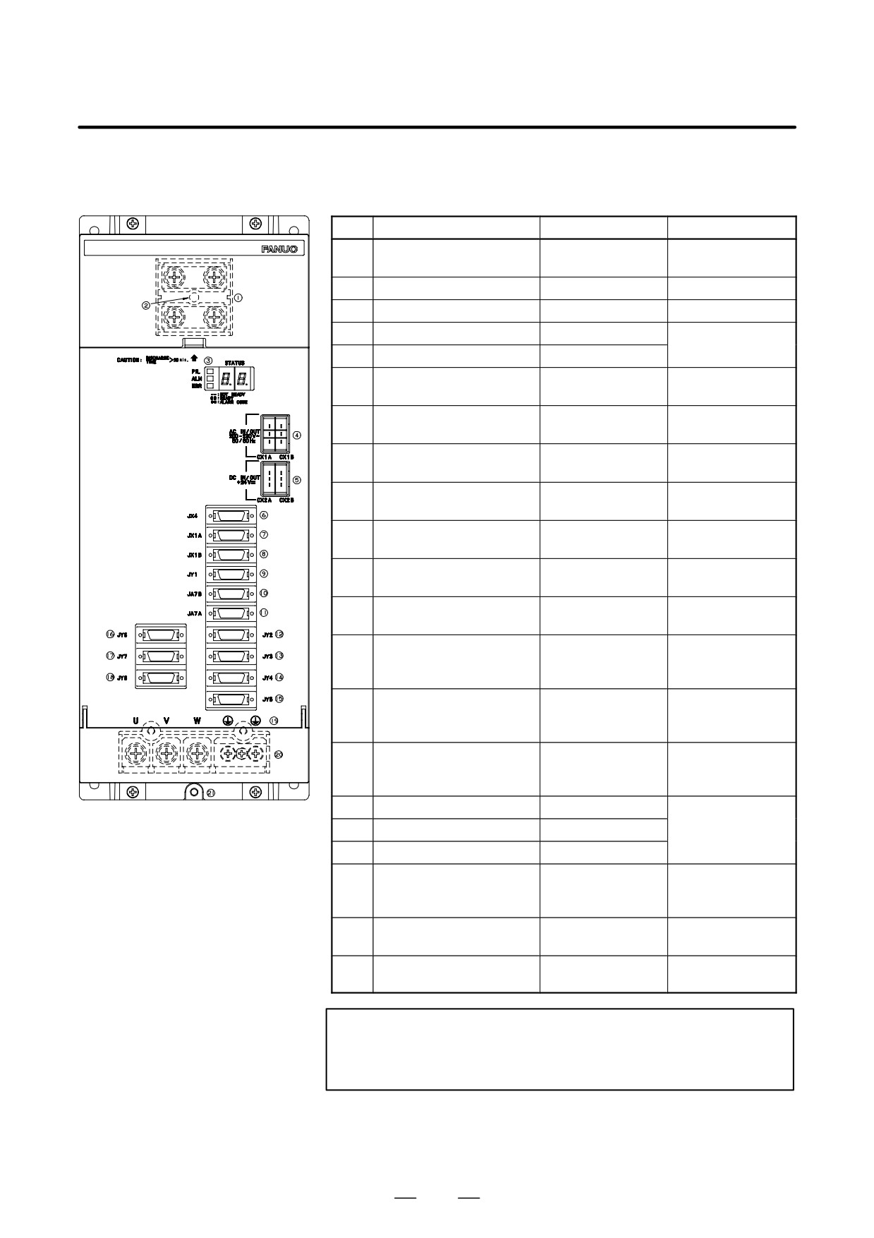
SPM-11, 15, 22, 26, 30 (TYPE 3)
Table.9.3.3 (e) Names of connectors and terminal blocks
Names
Display
Remarks
1
DC link terminal block
Display the terminal
block TB1
2
DC link charge LED
(Warning)
3
Status LED
STATUS
4
200VAC I/O connector
CX1A/CX1B
Both connectors
have same function
5
24 VDC I/O connector
CX2A/CX2B
6
Signal check connector
JX4
Use an SPM check
board.
7
Input connector for inter-
JX1A
face between modules
8
Output connector for inter-
JX1B
face between modules
9
Connector for load meter
JY1
and speedometer
10
Input connector for electric
JA7B
serial interface
11
Output connector for elec-
JA7A
tric serial interface
12
Connector for pulse gener-
JY2
ator, built-in sensor
13
Connector for magnetic
JY3
sensor and external single
rotation signal
14
Connector for position cod-
JY4
er and high-resolution
position coder
15
Connector for Cs-axis sen-
JY5
sor for spindle and built-in
Cs-axis sensor
16
Same as JY2
JY6
For spindle switch-
ing differential
17
Same as JY3
JY7
speed tapping.
18
Same as JY4
JY8
19
Terminal names for termi-
nal block for motor power
line
20
Terminal block for motor
TB2
Display the terminal
power line
block TB2
21
Tapped hole for grounding
the flange
WARNING
Do not touch module components or connected cables
while this LED is lit. There is a danger of electric shock.
346
B-65162E/03
9.CONNECTION
(f)
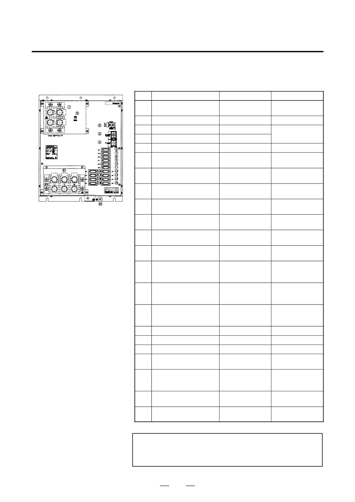
SPM-45, SPM-75HV (TYPE 3)
Table.9.3.3 (f) Names of connectors and terminal blocks
Names
Display
Remarks
1
DC link terminal block
Display the terminal
block TB1
2
Status LED
STATUS
3
200VAC I/O connector
CX1A/CX1B
Both connectors
have same function
4
24 VDC I/O connector
CX2A/CX2B
5
DC link charge LED
(Warning)
6
Signal check connector
JX4
Use an SPM check
board.
7
Input connector for inter-
JX1A
face between modules
8
Output connector for inter-
JX1B
face between modules
9
Connector for load meter
JY1
and speedometer
10
Input connector for electric
JA7B
serial interface
11
Output connector for elec-
JA7A
tric serial interface
12
Connector for pulse gener-
JY2
ator, built-in sensor
13
Connector for magnetic
JY3
sensor and external single
rotation signal
14
Connector for position cod-
JY4
er and high-resolution
position coder
15
Connector for Cs-axis sen-
JY5
sor for spindle and built-in
Cs-axis sensor
16
Same as JY2
JY6
17
Same as JY3
JY7
18
Same as JY4
JY8
19
Connector for position cod-
JY9
er signal output
20
Terminal names for termi-
nal block for motor power
line
21
Terminal block for motor
Display the terminal
power line
block TB2
22
Tapped hole for grounding
the flange
WARNING
Do not touch module components or connected cables
while this LED is lit. There is a danger of electric shock.
347
9. CONNECTION
B-65162E/03
(g)
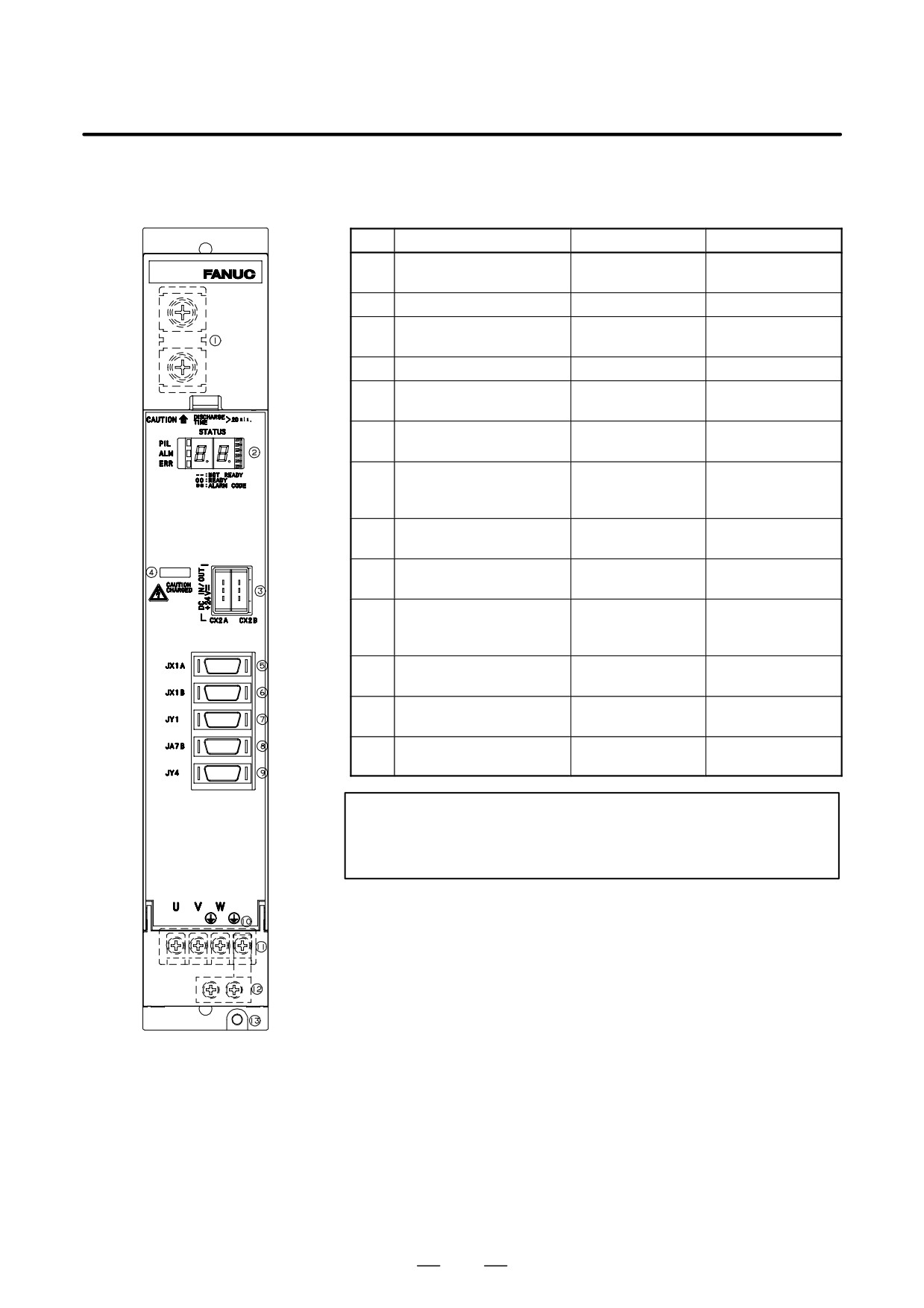
SPMC-2.2
Table.9.3.3 (g) Names of connectors and terminal blocks
Names
Display
Remarks
1
DC link terminal block
Display the terminal
block TB1
2
Status LED
STATUS
3
24VDC I/O connector
CX2A/CX2B
Both connectors
have same function
4
DC link charge LED
(Warning)
5
Output connector for inter-
JX1A
face between modules
6
Input connector for inter-
JX1B
face between modules
7
Frequency meter analog
JY1
override connector for mo-
tor thermostat connection
8
Input connector for electric
JA7B
serial interface
9
Connector for position cod-
JY4
er
10
Terminal names for termi-
nal block for motor power
line
11
Terminal block for motor
Display the terminal
power line
block TB2
12
Earth plate
Attatched to amplifi-
er
13
Tapped hole for grounding
the flange
WARNING
Do not touch module components or connected cables
while this LED is lit. There is a danger of electric shock.
348
B-65162E/03
9.CONNECTION
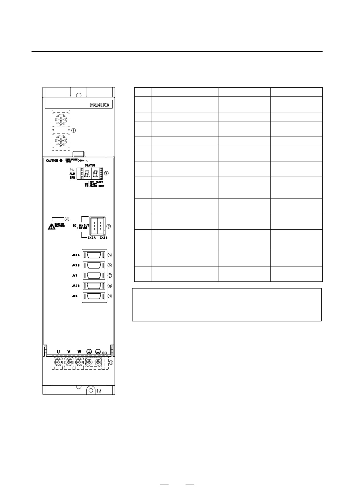
(h) SPMC-5.5, 11
Table.9.3.3 (h) Names of connectors and terminal blocks
Names
Display
Remarks
1
DC link terminal block
Display the terminal
block TB1
2
Status LED
STATUS
3
24VDC I/O connector
CX2A/CX2B
Both connectors
have same function
4
DC link charge LED
(Warning)
5
Output connector for inter-
JX1A
face between modules
6
Input connector for inter-
JX1B
face between modules
7
Frequency meter analog
JY1
override connector for mo-
tor thermostat connection
8
Input connector for electric
JA7B
serial interface
9
Connector for position cod-
JY4
er
10
Terminal names for termi-
nal block for motor power
line
11
Terminal block for motor
Display the terminal
power line
block TB2
12
Tapped hole for grounding
the flange
WARNING
Do not touch module components or connected cables
while this LED is lit. There is a danger of electric shock.
349
9. CONNECTION
B-65162E/03
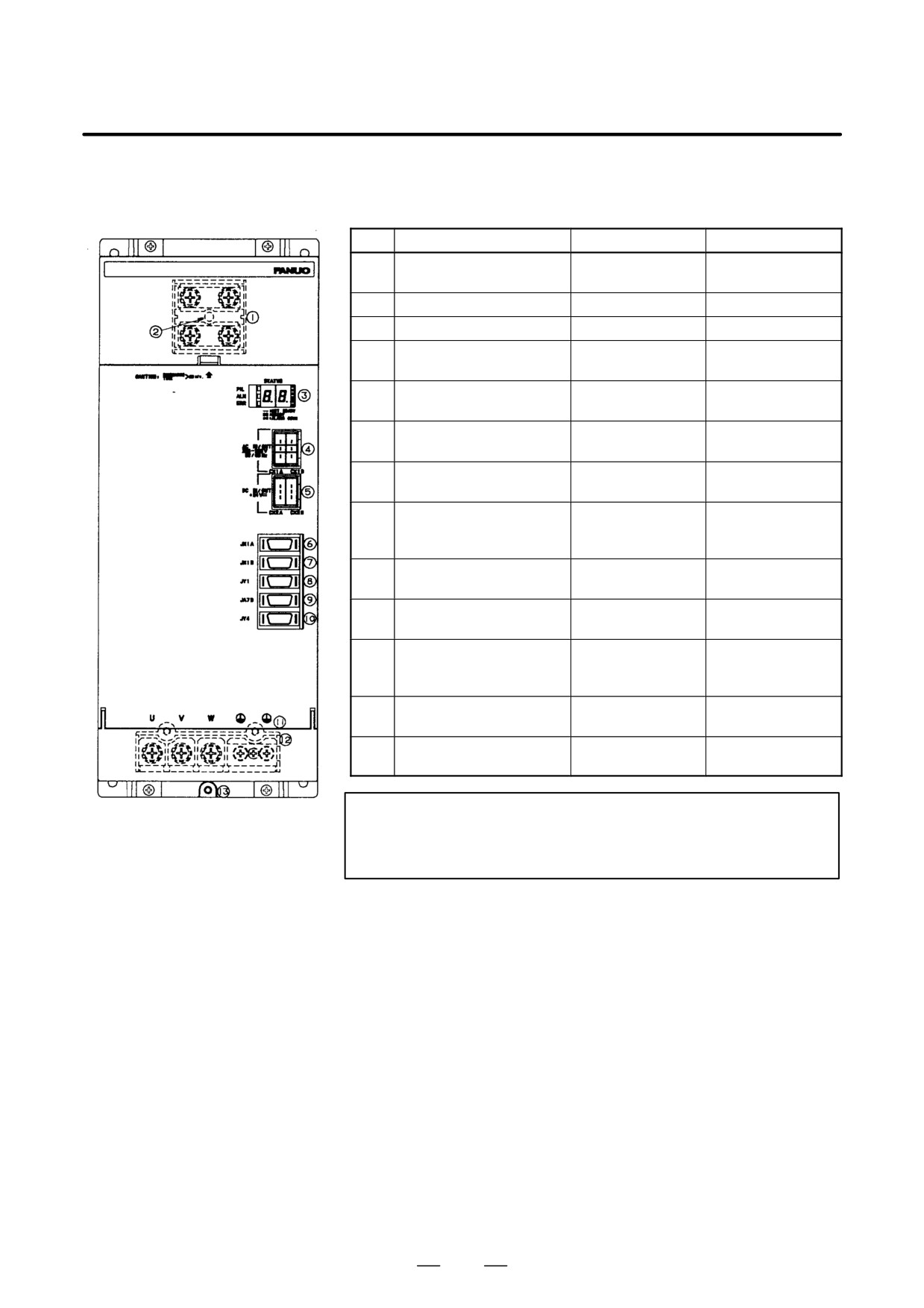
(i)
SPMC-15, -22, -26
Table.9.3.3 (i) Names of connectors and terminal blocks
Names
Display
Remarks
1
DC link terminal block
Display the terminal
block TB1
2
DC link charge LED
(Warning)
3
Status LED
STATUS
4
200VAC I/O connector
CX1A/CX1B
Both connectors
have same function.
5
24VDC I/O connector
CX2A/CX2B
Both connectors
have same function
6
Output connector for inter-
JX1A
face between modules
7
Input connector for inter-
JX1B
face between modules
8
Frequency meter analog
JY1
override connector for mo-
tor thermostat connection
9
Input connector for electric
JA7B
serial interface
10
Connector for position cod-
JY4
er
11
Terminal names for termi-
nal block for motor power
line
12
Terminal block for motor
Display the terminal
power line
block TB2
13
Tapped hole for grounding
the flange
WARNING
Do not touch module components or connected cables
while this LED is lit. There is a danger of electric shock.
350
B-65162E/03
9.CONNECTION
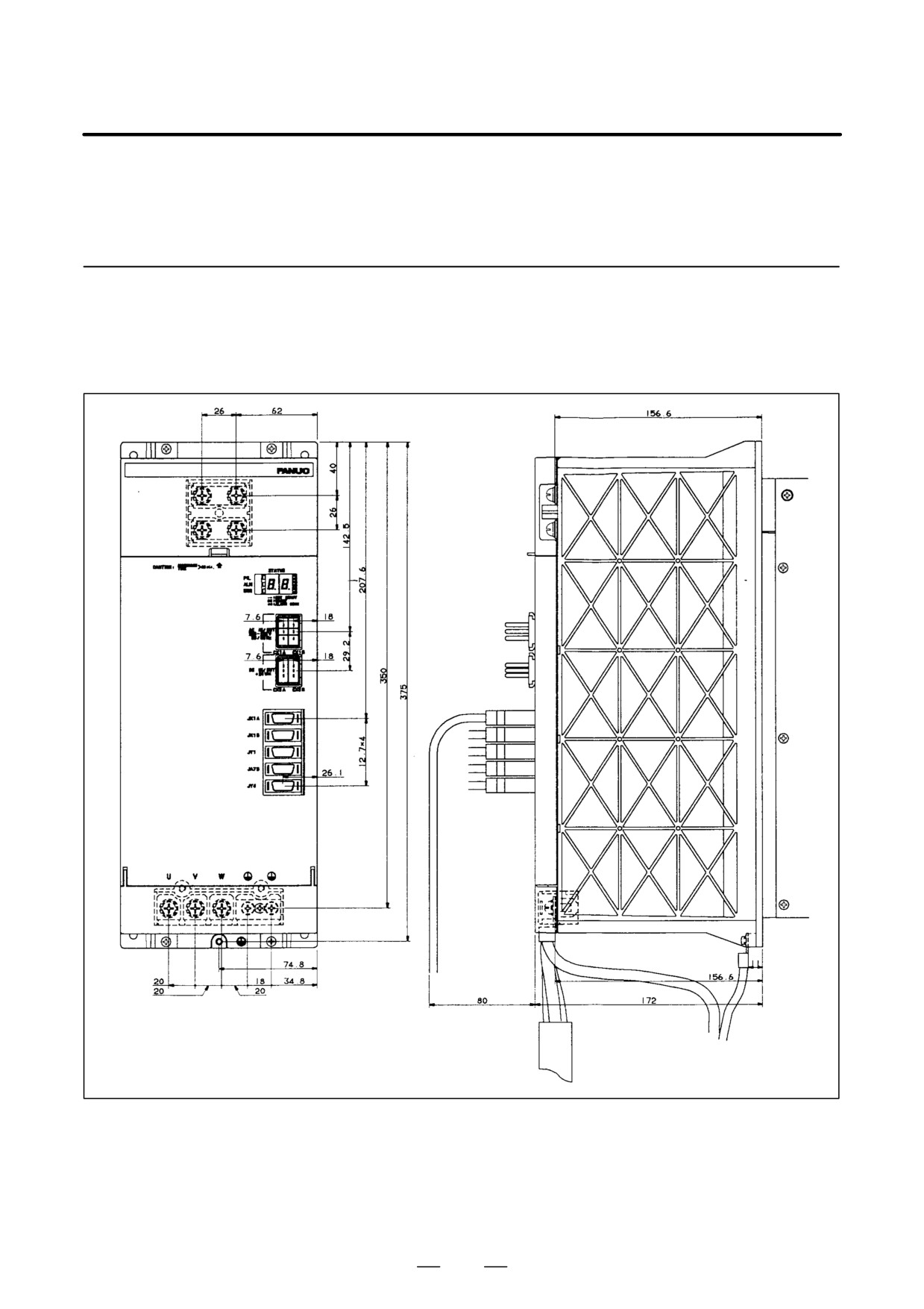
9.4
CABLE LEAD-IN
DIAGRAMS
9.4.1
Power Supply Modules
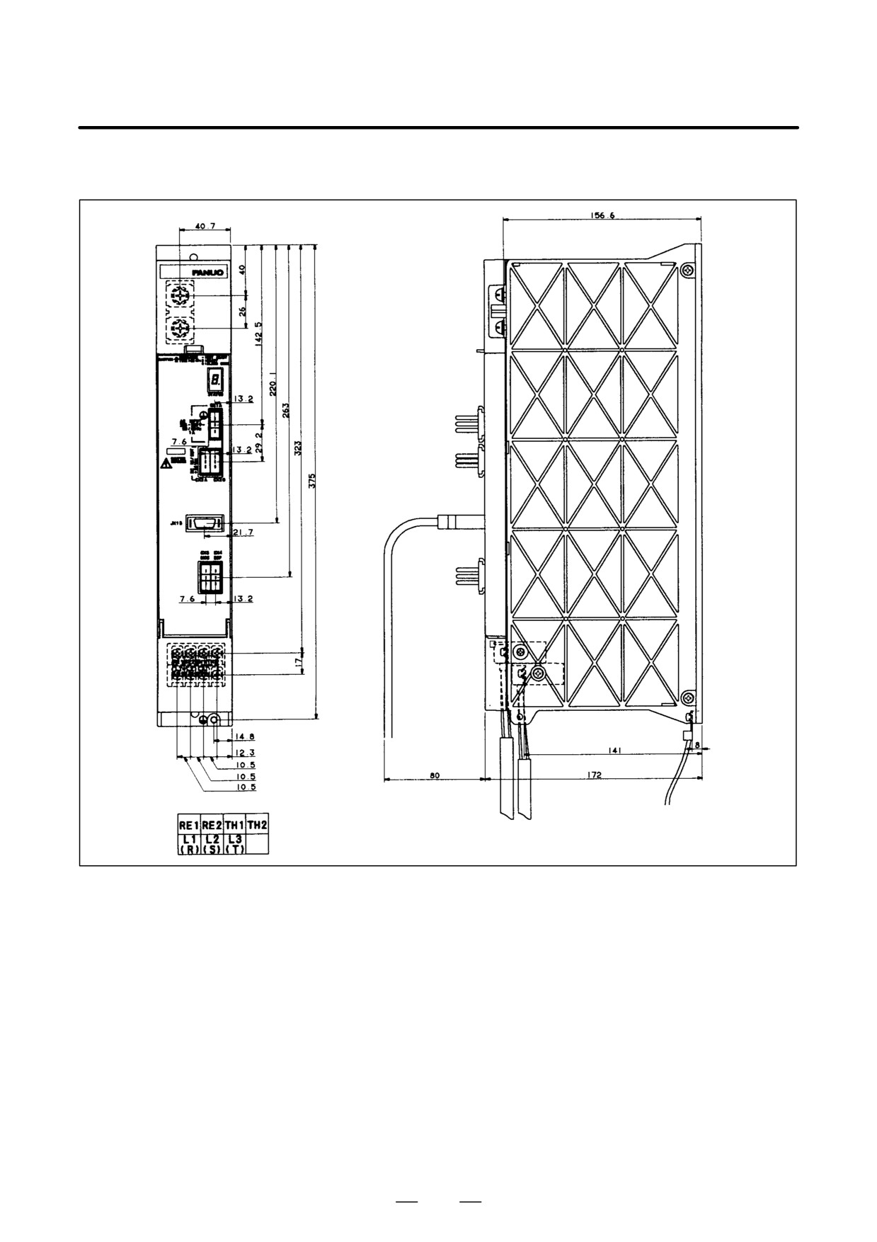
(a) PSM-5.5, PSM-11
351
9. CONNECTION
B-65162E/03
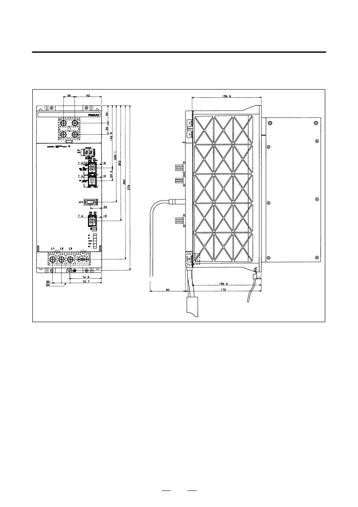
(b) PSM-15, PSM-26, PSM-30,
PSM-37, PSM-18HV, PSM-30HV,
PSM-45HV
352
B-65162E/03
9.CONNECTION
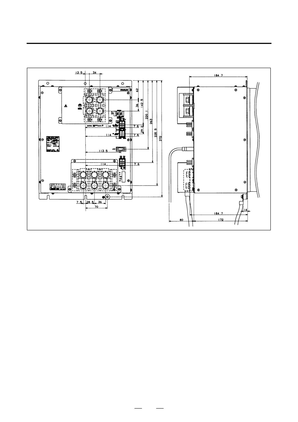
(c) PSMR-3, PSMR-5.5
353
9. CONNECTION
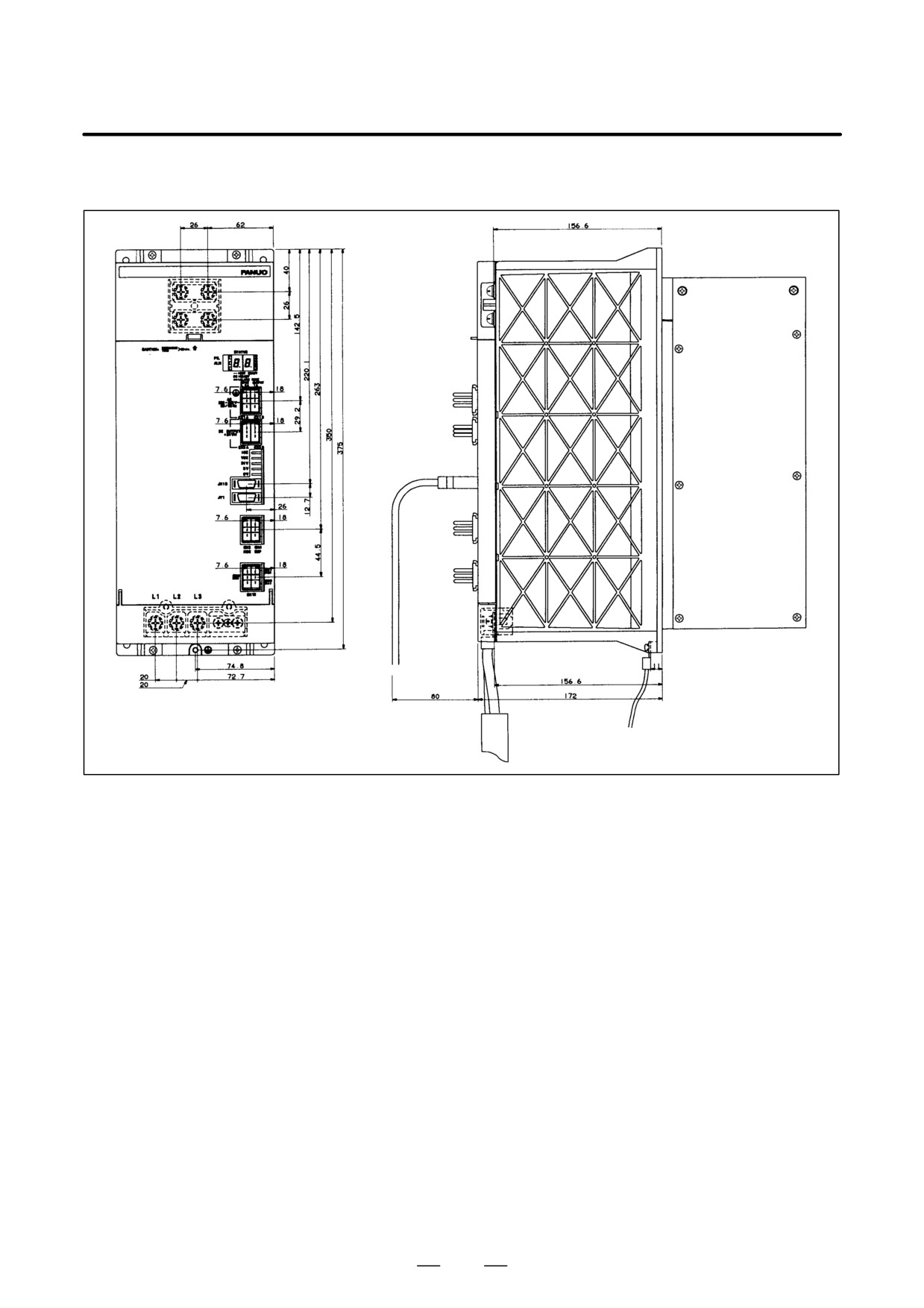
B-65162E/03
(d) PSM-45, PSM-75HV
354
B-65162E/03
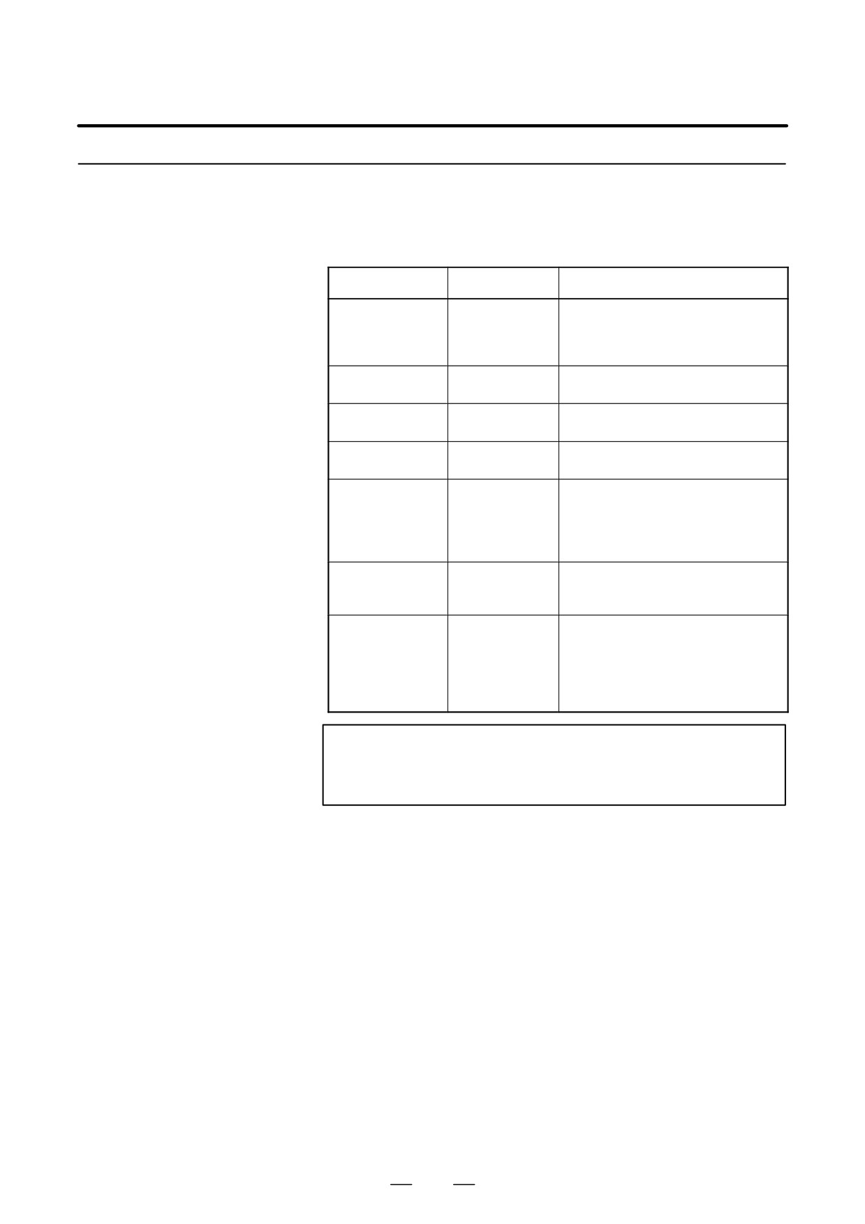
9.CONNECTION
(e) PSMV-11HV
355
9. CONNECTION
B-65162E/03
9.4.2
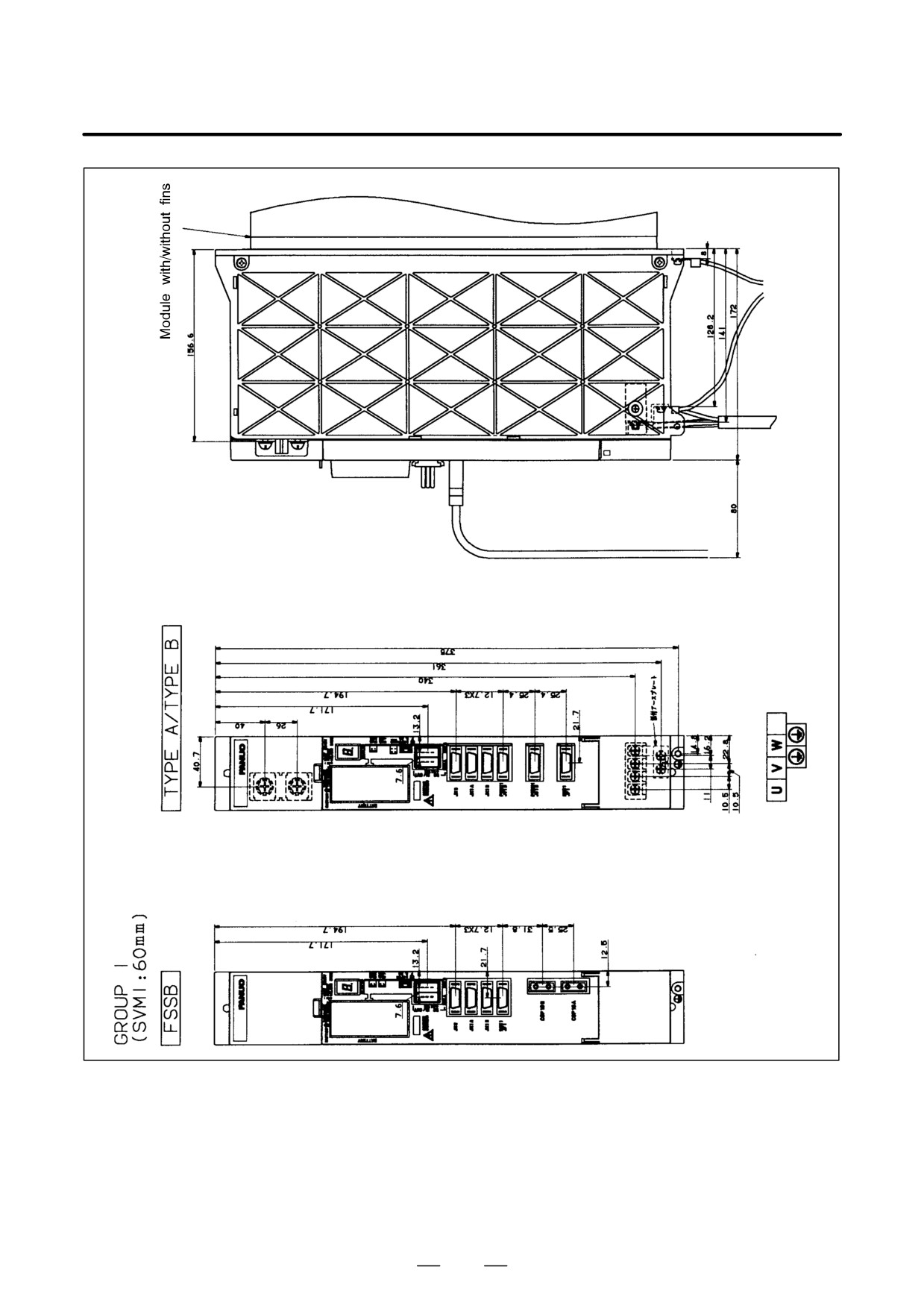
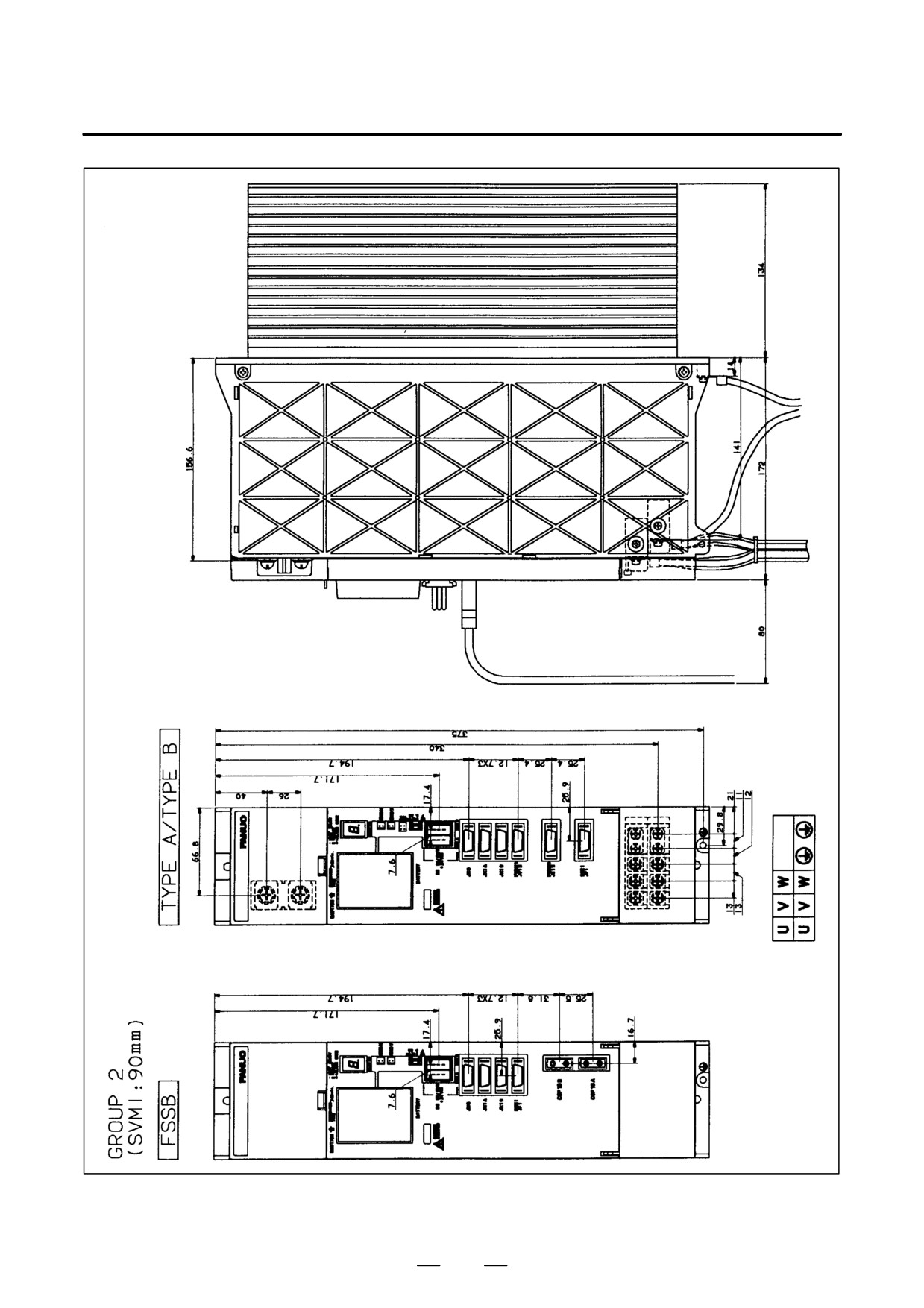
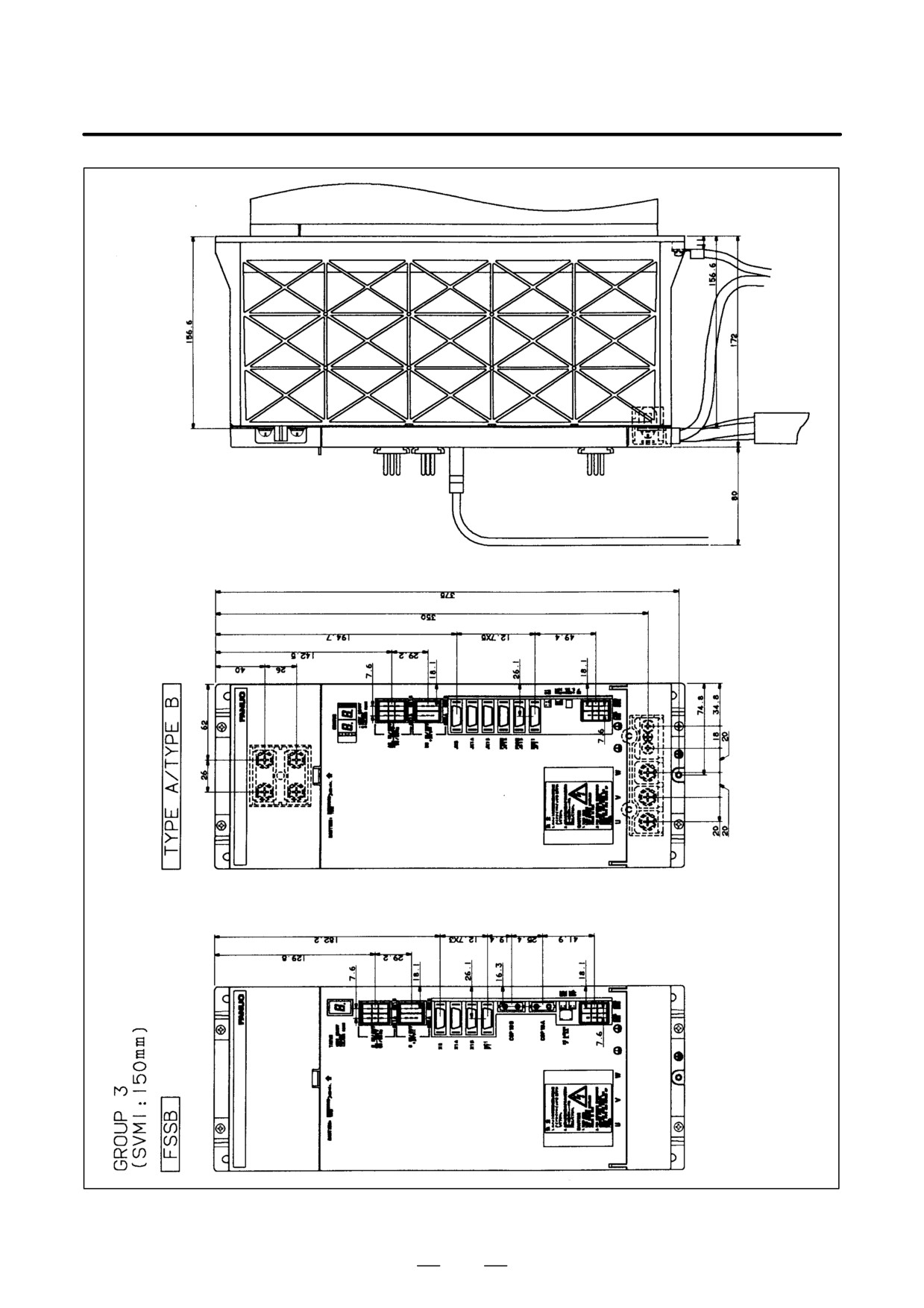
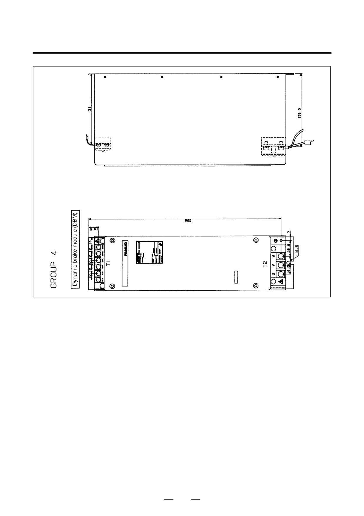
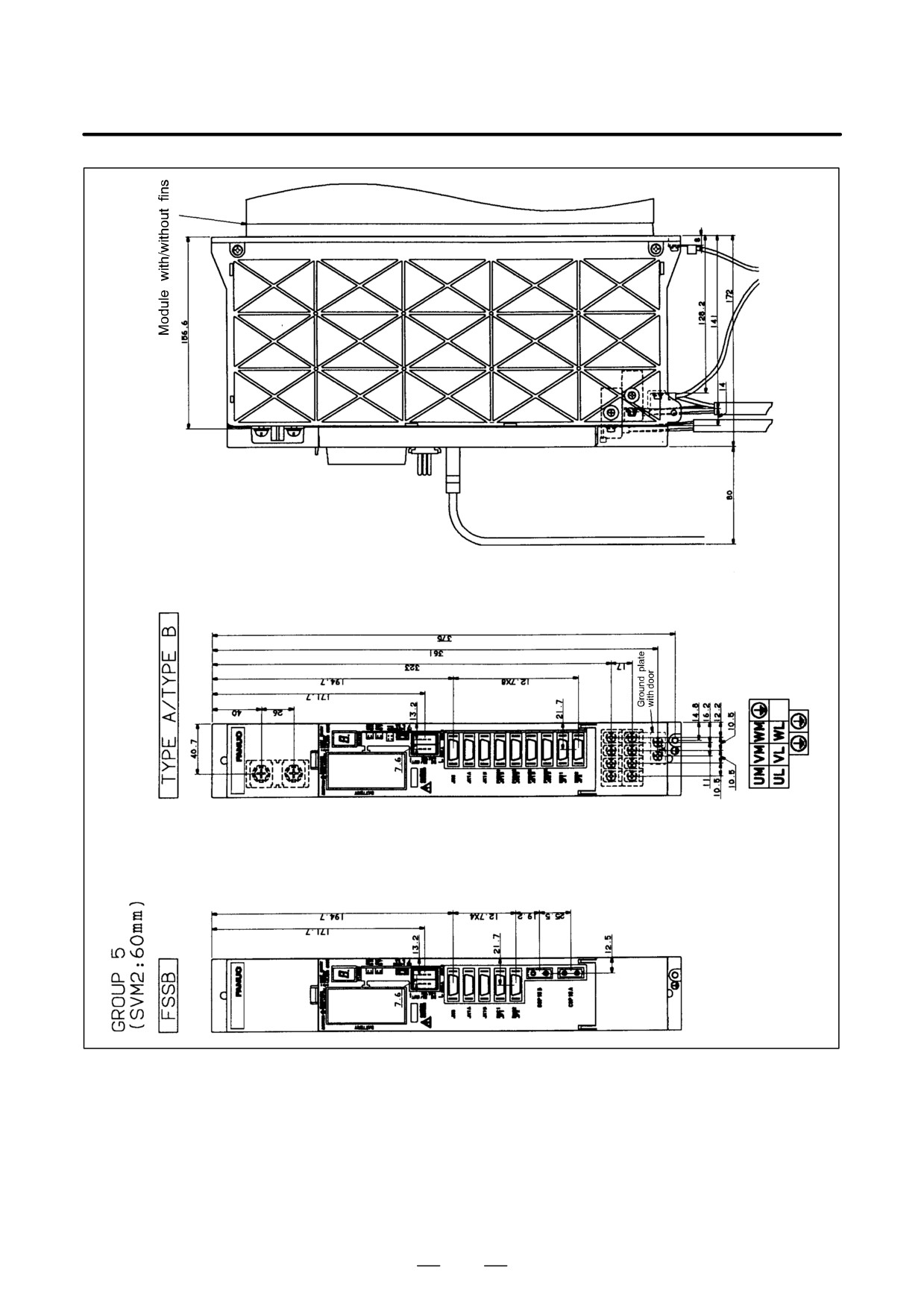
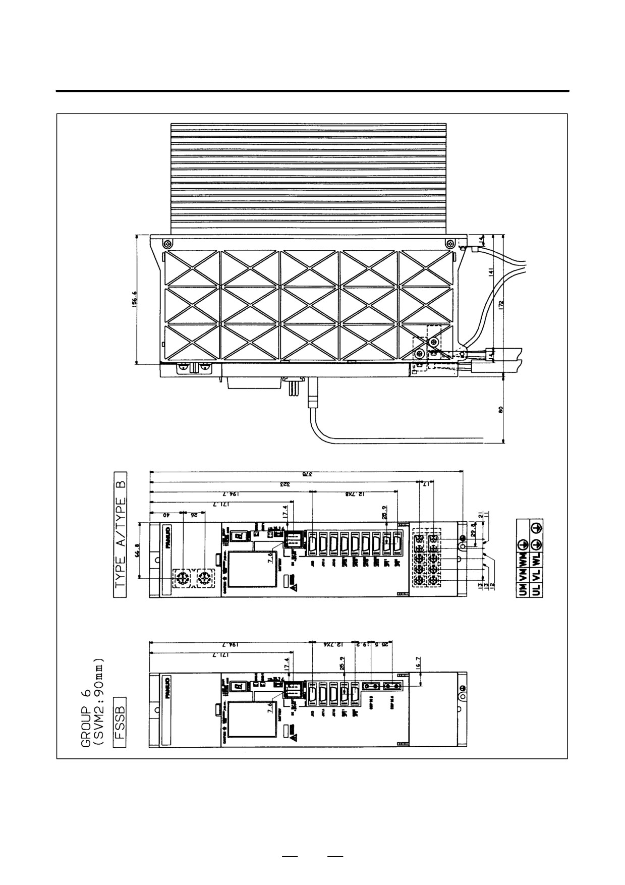
Select a group of cable lead-in drawings corresponding to your module
from the following table.
Servo Amplifier
Modules
Table.9.4.2 Cable Lead-in Drawing Groups
Group
Interface
Name
- Module without fins
GROUP 1
TYPE A/TYPE B
SVM1-12, SVM1-20
(SVM1:60mm)
FSSB
- Module with fins
SVM1-40S, SVM1-40L, SVM1-80
GROUP 2
TYPE A/TYPE B
SVM1-130
(SVM1:90mm)
FSSB
SVM1-jHV
GROUP 3
TYPE A/TYPE B
SVM1-240, SVM1-360
(SVM1:150mm)
FSSB
Dynamic brake module (DBM) for the
GROUP 4
---
SVM1-240 and SVM1-360
- Module without fins
SVM2-12/12, SVM2-12/20
GROUP 5
TYPE A/TYPE B
SVM2-20/20
(SVM2:60mm)
FSSB
- Module with fins
SVM2-40/40
SVM2-40/80, SVM2-80/80
GROUP 6
TYPE A/TYPE B
SVM2-40L/40L
(SVM2:90mm)
FSSB
SVM2-j/jHV
- Module without fins
SVM3-12/12/12, SVM3-12/12/20
TYPE A
GROUP 7
SVM3-12/20/20, SVM3-20/20/20
TYPE B
(SVM3:90mm)
- Module with fins
FSSB
SVM3-12/12/40, SVM3-12/20/40
SVM3-20/20/40
NOTE
(SVM*: jmm): jmm is the width of a servo amplifier
(where * represents 1, 2, or 3.)
356
B-65162E/03
9.CONNECTION
357
9. CONNECTION
B-65162E/03
358
B-65162E/03
9.CONNECTION
359
9. CONNECTION
B-65162E/03
360
B-65162E/03
9.CONNECTION
361
9. CONNECTION
B-65162E/03
362