FANUC SERVO AMPLIFIER a series. DESCRIPTIONS (B-65162E/03) - page 11
B-65162E/03
9.CONNECTION
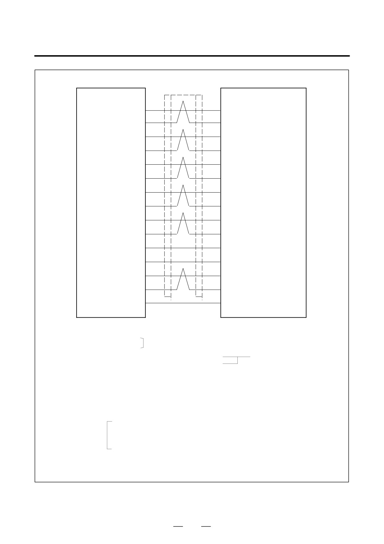
Detailed description of the connection of cable K18
SPM
JY5
CN2
High-resolution
magnetic pulse
A1
A1
coder preamplifier
(3)
(16)
(Motor side)
RA1
RA1
(4)
(17)
B1
B1
(17)
(18)
RB1
RB1
(19)
(19)
MZ
Z
(1)
(14)
*MZ
*Z
(2)
(15)
A3
A3
(5)
(10)
RA3
RA3
(6)
(11)
B3
B3
(7)
(12)
RB3
RB3
(8)
(13)
+5V
+5V
(9), (18), (20)
(4), (5), (6)
0V
0V
(12), (14), (16)
(1), (2), (3)
OH1
OH1
(13)
(8)
OH2
OH2
(15)
(9)
SS
SS
(10)
F
F
(7)
Required connector (HIROSE)
Required connector (HIROSE)
Connector FI40B-20S
HR22-12WTPA-20S (Note)
FI40B-20S-CV5
Housing
FI-20-CV5
Cable specification : Six
0.18mm2
twisted pairs
Common shielded cable
Six
0.5mm2
wires
Cable:
+5V, 0V...three 0.18 mm2 wires each
PA, *PA, PB, *PB, MZ, *MZ, VA2, *VA2, VB2, *VB2, OH1, OH2...0.18 mm2 twisted pair
Recommended cable specification (wire only): A66L-0001-0367
See Appendix C for details.
(Note)In addition to a soldering type, a crimping type can be selected.
Crimping type
Crimp pin
: HR22-SC-122
(20 pins are required for each connector.)
Connector housing : HR22-12WTPA-20SC
Soldering type
: HR22-12WTPA-20S
Crimping type connectors require the use of the following crimping tool:
Crimping tool specification: HR22-TA-2428HC (HIROSE)
303
9. CONNECTION
B-65162E/03
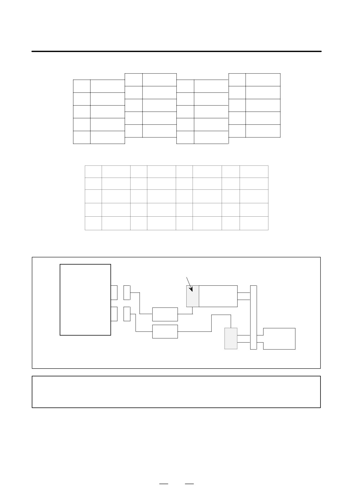
Pin arrangement of connector JY5
10
SS
20
+5V
9
+5V
19
RB1
8
RB3
18
+5V
7
B3
17
B1
6
RA3
16
0V
5
A3
15
OH2
4
RA1
14
0V
3
A1
13
OH1
2
*Z
12
0V
1
Z
11
Pin arrangement of connector for the high-resolution magnetic pulse coder preamplifier
3
4
+5V
1
0V
2
0V
0V
5
+5V
6
+5V
7
G
8
OH1
9
OH2
10
A3
11
RA3
12
B3
13
RB3
14
Z
15
*Z
16
A1
17
RA1
18
B1
19
RB1
20
(20) Use of high-resolution magnetic pulse coders (for the spindle and motor separately)
SPM
High-resolution magnetic pulse coder
TYPE 2
JY2
Spindle motor
Preamplifier
K18
JY5
K19
Spindle
Preamplifier
High-resolution magnetic pulse coder
NOTE
If one high-resolution magnetic pulse coder is used for the spindle and another for the motor,
cable K18 must be attached to connector JY2.
304
B-65162E/03
9.CONNECTION
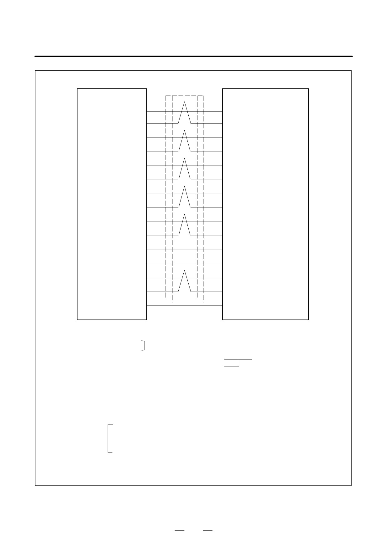
Detailed description of the connection of cable K18
SPM
JY2
CN2
High-resolution
magnetic pulse
VA2
A1
coder preamplifier
(3)
(16)
(Motor side)
*VA2
RA1
(4)
(17)
VB2
B1
(17)
(18)
*VB2
RB1
(19)
(19)
MZ
Z
(1)
(14)
*MZ
*Z
(2)
(15)
PA
A3
(5)
(10)
*PA
RA3
(6)
(11)
PB
B3
(7)
(12)
*PB
RB3
(8)
(13)
+5V
+5V
(9), (18), (20)
(4), (5), (6)
0V
0V
(12), (14), (16)
(1), (2), (3)
OH1
OH1
(13)
(8)
OH2
OH2
(15)
(9)
SS
SS
(10)
F
F
(7)
Required connector (HIROSE)
Required connector (HIROSE)
Connector FI40B-20S
HR22-12WTPA-20S (Note)
FI40B-20S-CV5
Housing
FI-20-CV5
Cable specification : Six
0.18mm2
twisted pairs
Common shielded cable
Six
0.5mm2
wires
Cable:
+5V, 0V...three 0.18 mm2 wires each
PA, *PA, PB, *PB, MZ, *MZ, VA2, *VA2, VB2, *VB2, OH1, OH2...0.18 mm2 twisted pair
Recommended cable specification (wire only): A66L-0001-0367
See Appendix C for details.
(Note)In addition to a soldering type, a crimping type can be selected.
Crimping type
Crimp pin
: HR22-SC-122
(20 pins are required for each connector.)
Connector housing : HR22-12WTPA-20SC
Soldering type
: HR22-12WTPA-20S
Crimping type connectors require the use of the following crimping tool:
Crimping tool specification: HR22-TA-2428HC (HIROSE)
305
9. CONNECTION
B-65162E/03
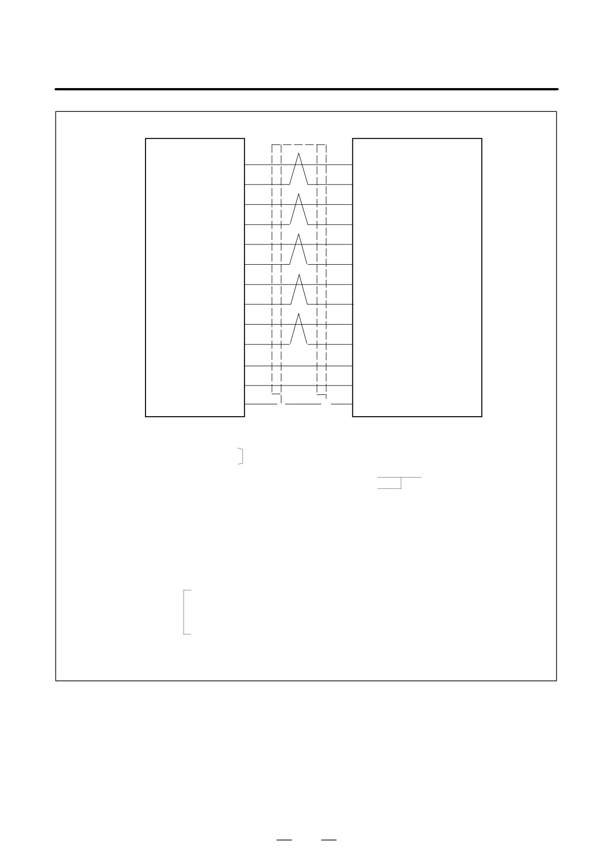
Detailed description of the connection of cable K19
SPM
JY5
CN2
High-resolution
A1
A1
magnetic pulse
(3)
(16)
coder preamplifier
RA1
RA1
(Spindle side)
(4)
(17)
B1
B1
(17)
(18)
RB1
RB1
(19)
(19)
Z
Z
(1)
(14)
*Z
*Z
(2)
(15)
A3
A3
(5)
(10)
RA3
RA3
(6)
(11)
B3
B3
(7)
(12)
RB3
RB3
(8)
(13)
+5V
+5V
(9), (18), (20)
(4), (5), (6)
0V
0V
(12), (14), (16)
(1), (2), (3)
SS
SS
(10)
F
F
(7)
Required connector (HIROSE)
Required connector (HIROSE)
Connector FI40A-20S
HR22-12WTPA-20S (Note)
FI40A-20S-CV5
Housing FI-20-CV5
Cable specification : Five
0.18mm2
twisted pairs
Common shielded cable
Six
0.5mm2
wires
Cable:
+5V, 0V...three 0.18 mm2 wires each
A1, RA1, B1, RB1, Z, *Z, A3, RA2, B3, RB3...0.18 mm2 twisted pair
Recommended cable (wire only): A66L-0001-0367
See Appendix C for details.
(NOTE) In addition to the soldering type, a crimping type can also be selected.
Crimping type
Crimp pin
: HR22-SC-122
(20 pins are required for each connector.)
Connector housing : HR22-12WTPA-20SC
Soldering type
: HR22-12WTPA-20S
Crimping type connectors require the use of the following crimping tool:
Crimping tool specification: HR22-TA-2428HC (HIROSE)
306
B-65162E/03
9.CONNECTION
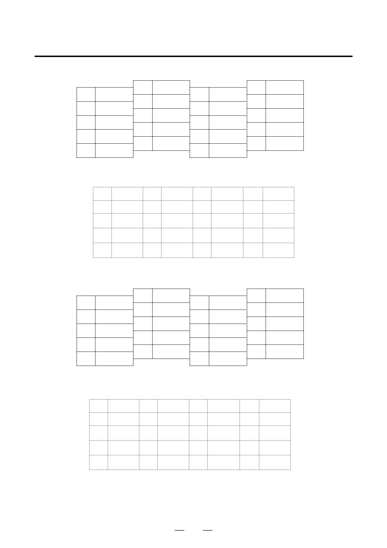
Pin arrangement of connector JY2
10
SS
20
+5V
9
+5V
19
*VB2
8
*PB
18
+5V
7
PB
17
VB2
6
*PA
16
0V
5
PA
15
OH2
4
*VA2
14
0V
3
VA2
13
OH1
2
*MZ
12
0V
1
MZ
11
Pin arrangement of the connector for the high-resolution magnetic pulse coder preamplifier (on the motor side)
2
3
4
+5V
1
0V
0V
0V
5
8
+5V
6
+5V
7
G
OH1
9
OH2
10
A3
11
RA3
12
B3
13
RB3
14
Z
15
*Z
16
A1
17
RA1
18
B1
19
RB1
20
Pin arrangement of connector JY5
10
SS
20
+5V
9
+5V
19
RB1
8
RB3
18
+5V
7
B3
17
B1
6
RA3
16
0V
5
A3
15
4
RA1
14
0V
3
A1
13
2
*Z
12
0V
1
Z
11
Pin arrangement of the connector for the high-resolution magnetic pulse coder preamplifier (on the spindle side)
2
3
4
+5V
1
0V
0V
0V
5
8
+5V
6
+5V
7
G
9
10
A3
11
RA3
12
B3
13
RB3
14
Z
15
*Z
16
A1
17
RA1
18
B1
19
RB1
20
307
9. CONNECTION
B-65162E/03
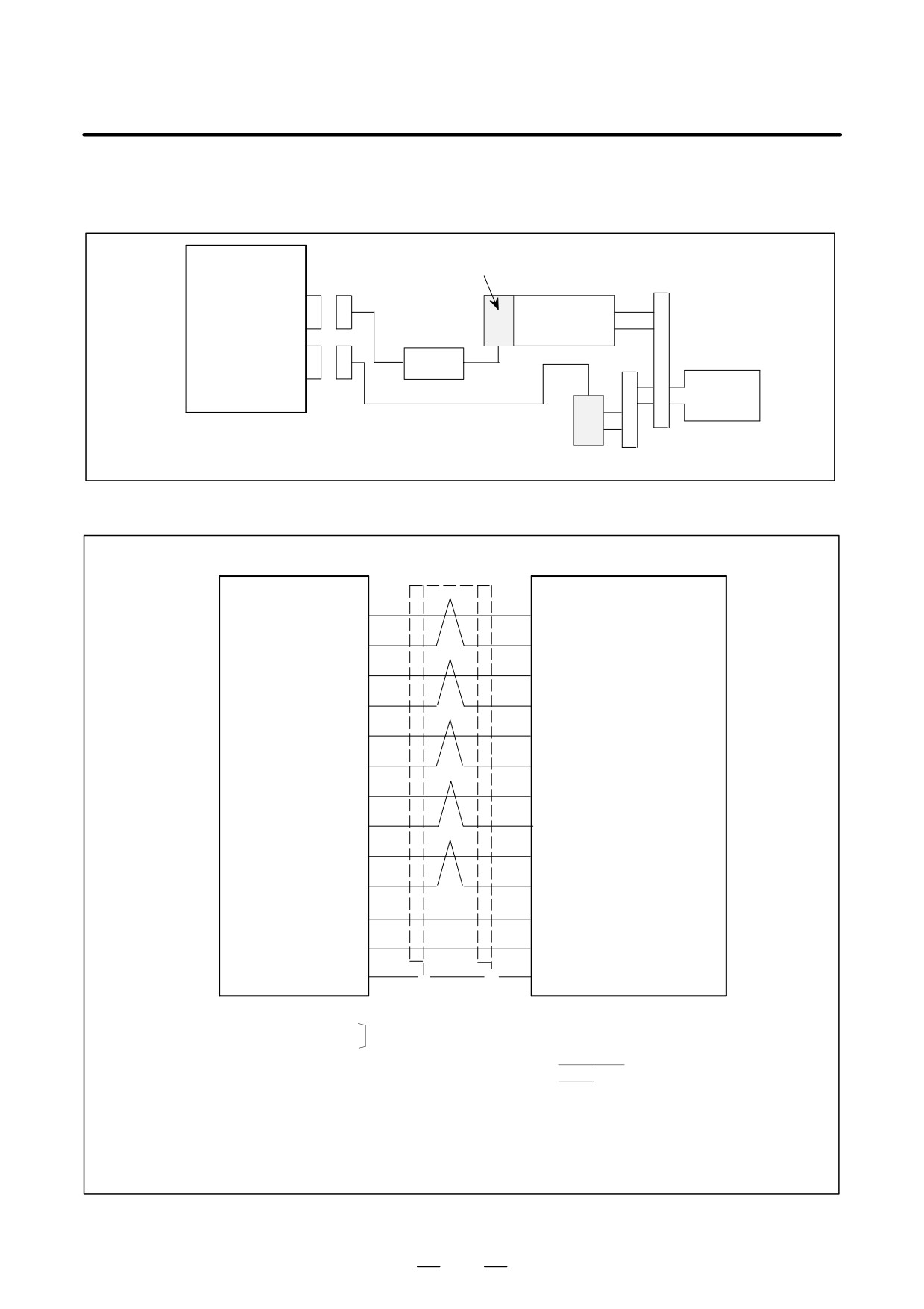
(21) Combined use of the high-resolution magnetic pulse coder incorporated into the motor and the
high-resolution position coder
SPM
High-resolution magnetic pulse coder
TYPE 2
JY2
Spindle motor
Preamplifier
K18
JY4
K31
Spindle
High-resolution position coder
Detailed description of the connection of cable K31
SPM
JY4
High-resolution
PAE
PAE
position coder
(5)
(M)
*PAE
*PAE
(6)
(L)
PBE
PBE
(7)
(P)
*PBE
*PBE
(8)
(C)
PSE
PSE
(1)
(F)
*PSE
*PSE
(2)
(G)
AP
AP
(3)
(A)
XAP
XAP
(4)
(D)
BP
BP
(17)
(B)
XBP
XBP
(19)
(E)
+5V
+5V
(9), (18), (20)
(J), (K)
0V
0V
(12), (14), (16)
(N), (T)
SS
SS
(10)
F
F
(H)
Required connector (HIROSE)
Required connector Canon connector
Connector FI40B-20S
(HIROSE ELECTRIC)
FI40B-20S-CV5
MS3106A20-29SW
Housing
FI-20-CV5
Cable specification : Five
0.18mm2
twisted pairs
Common shielded cable
Six
0.5mm2
wires
Cable
+5V, 0V...three 0.5 mm2 wires each
PAE, *PAE, PBE, *PBE, PSE, *PSE, AP, XAP, BP, XBP...0.18 mm2 twisted pair
Recommended cable: A66L-0001-0368
See Appendix C for details.
308
B-65162E/03
9.CONNECTION
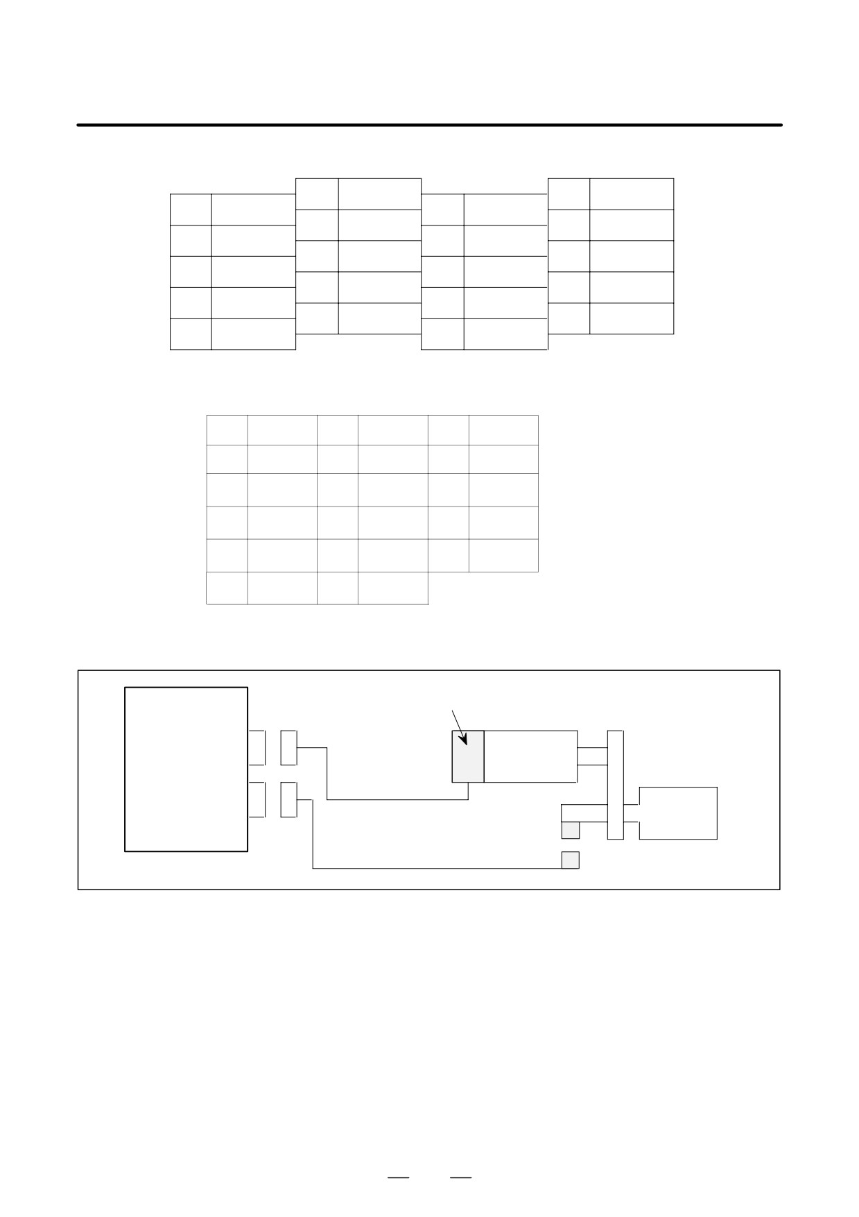
Pin arrangement of connector JY4
10
SS
20
+5V
9
5V
19
XBP
8
*PBE
18
+5V
7
PBE
17
BP
6
*PAE
16
0V
5
PAE
15
4
XAP
14
0V
3
AP
13
2
*PSE
12
0V
1
PSE
11
Pin arrangement of the connector for the high-resolution pulse coder
A
AP
B
BP
C
*PBE
D
XAP
E
XBP
F
PSE
G
*PSE
H
SS
J
+5V
K
+5V
L
*PAE
M
PAE
N
0V
P
PBE
R
S
T
0V
(22) Combined use of the MZ sensor (built-in sensor) and external one-turn signal switch
SPM
MZ sensor (built-in sensor)
TYPE I
JY2
Spindle motor
K17
JY3
Spindle
K32
External one-turn signal switch
(proximity switch)
309
9. CONNECTION
B-65162E/03
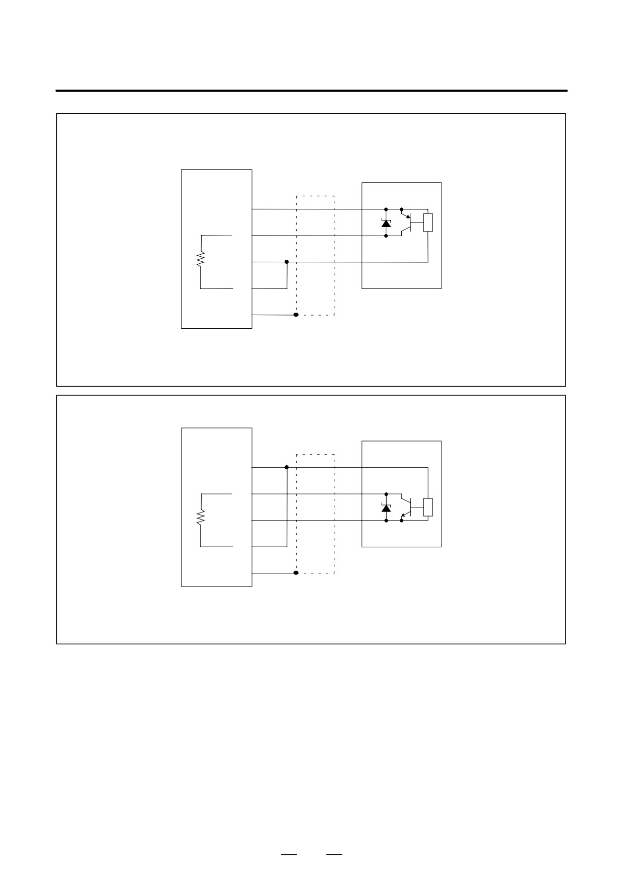
Detailed descriptions about the connection of cable K32
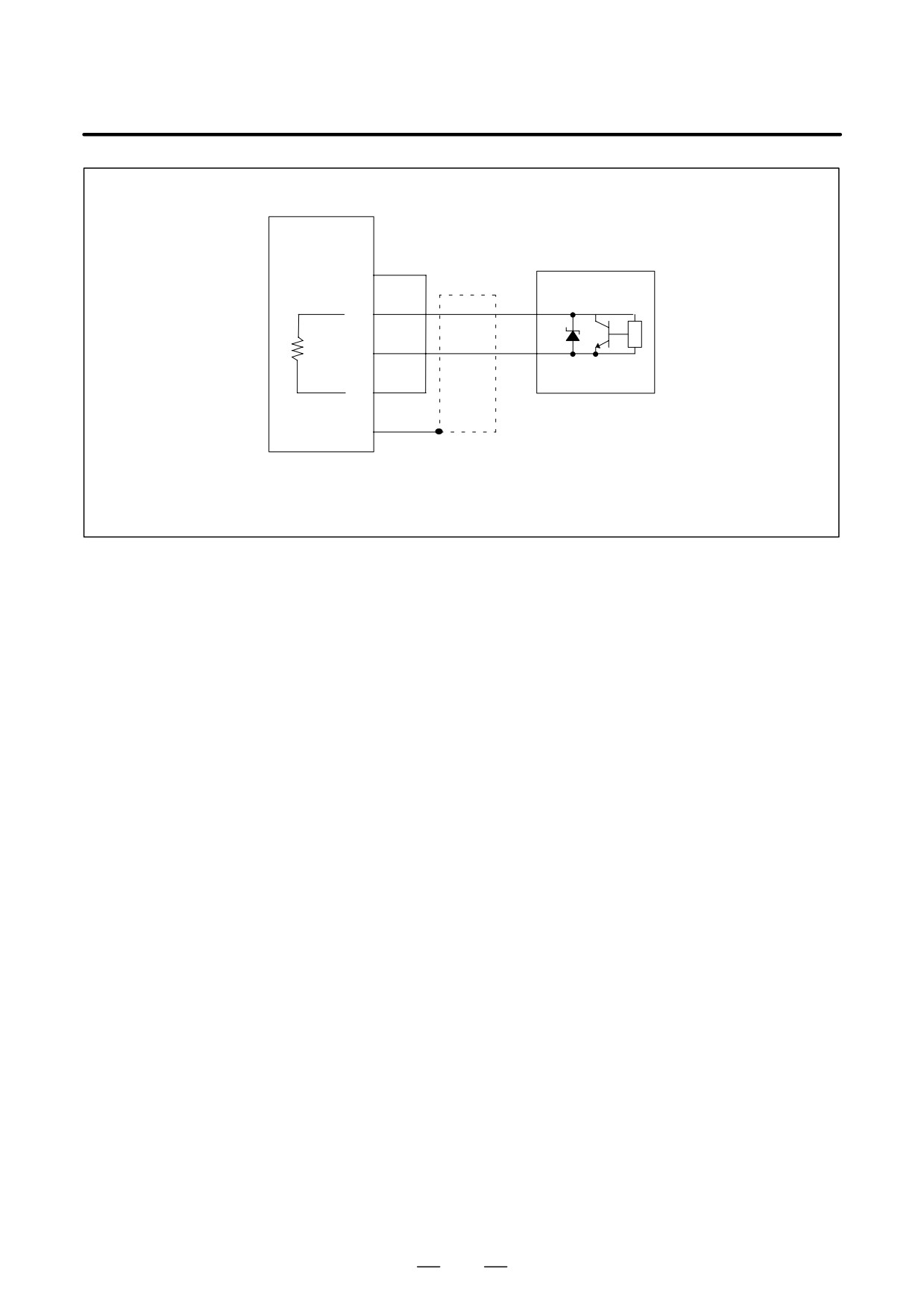
Three-wire proximity switch/PNP type
Proximity switch
SPM
JY3
(11)
24V
24V
OUT-
(18)
EXTSC
PUT
(16)
0V
0V
(13)
PU/PD
(10)
SS
Required connector (HIROSE)
Connector FI40A-2015S
Housing
FI-20-CV
Three-wire proximity switch/NPN type
Proximity switch
SPM
JY3
(11)
24V
24V
OUT-
(18)
EXTSC
PUT
(16)
0V
0V
(13)
PU/PD
(10)
SS
Required connector (HIROSE)
Connector FI40A-2015S
Housing
FI-20-CV
310
B-65162E/03
9.CONNECTION
Two-wire proximity switch/NPN type
SPM
JY3
Proximity switch
(11)
24V
OUT-
(18)
EXTSC
PUT
(16)
0V
0V
(13)
PU/PD
(10)
SS
Required connector (HIROSE)
Connector FI40A-2015S
Housing
FI-20-CV
311
9. CONNECTION
B-65162E/03
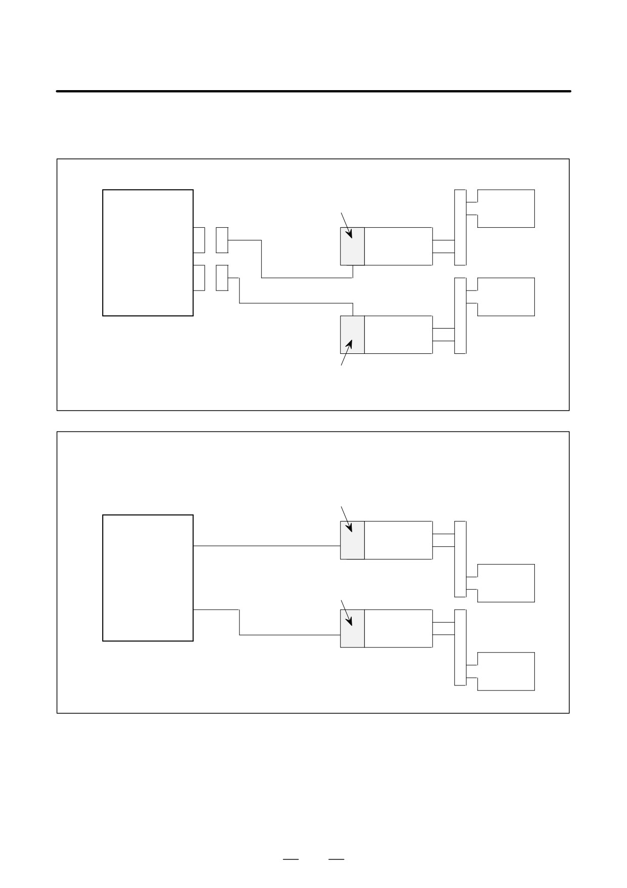
(23) Spindle switch control (TYPE 3 only)
Shown below are examples of spindle switch control connection.
Example 1) Switching the speed feedback signal
SPM
TYPE 3
M sensor (pulse generator)
Main spindle
JY2
Spindle motor
K14
JY6
K14
Sub spindle
Spindle motor
M sensor (pulse generator)
See 9.2.3 (10) and (11) for a detailed description of the connection of cable K14.
Example 2) Switching the speed and position feedback signals
Example 2-1) Both main spindle and subspindle motors incorporating an MZ sensor
MZ sensor (built-in sensor)
SPM
TYPE 3
K17
Spindle motor
JY2
Main spindle
MZ sensor (built-in sensor)
K17
JY6
Spindle motor
Sub spindle
See 9.2.3 (17) for a detailed description of the connection of cable K17.
312
B-65162E/03
9.CONNECTION
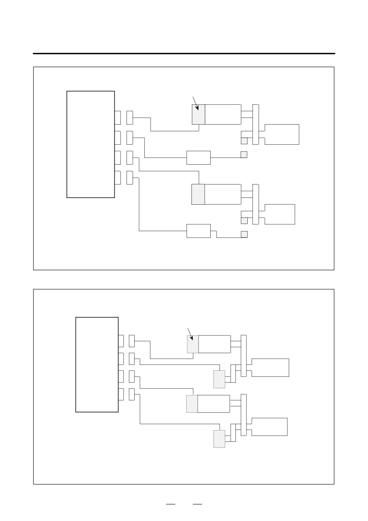
Example 2-2) Using a magnetic sensor for orientation
M sensor (pulse generator)
SPM
TYPE 3
Spindle motor
JY2
K14
Main spindle
JY3
Magnetic sensor amplifier
K15
JY6
Magnetic sensor
K14
JY7
M sensor
Spindle motor
(pulse generator)
Sub spindle
Magnetic sensor amplifier
K15
See 9.2.3 (10) and (11) for a detailed description of the connection of cable K14.
See 9.2.3 (15) for a detailed description of the connection of cable K15.
Example 2-3) Using a position coder for the position feedback signal
SPM
M sensor (pulse generator)
TYPE 3
JY2
Spindle
motor
K14
JY4
K16
Main spindle
JY6
Position coder
K14
JY8
M sensor
Spindle
(pulse generator)
motor
K16
Sub spindle
Position coder
See 9.2.3 (10) and (11) for a detailed description of the connection of cable K14.
See 9.2.3 (16) for a detailed description of the connection of cable K16.
313
9. CONNECTION
B-65162E/03
Example 2-4) Using a motor incorporating an MZ sensor (built-in sensor) for the main spindle and a
position coder for the subspindle
SPM
MZ sensor (built-in sensor)
TYPE 3
JY2
Spindle
motor
K17
Main spindle
JY6
K14
JY8
Spindle
M sensor
motor
(pulse generator)
Sub spindle
K16
Position coder
See 9.2.3 (10) and (11) for a detailed description of the connection of cable K14.
See 9.2.3 (16) for a detailed description of the connection of cable K16.
See 9.2.3 (17) for a detailed description of the connection of cable K17.
314
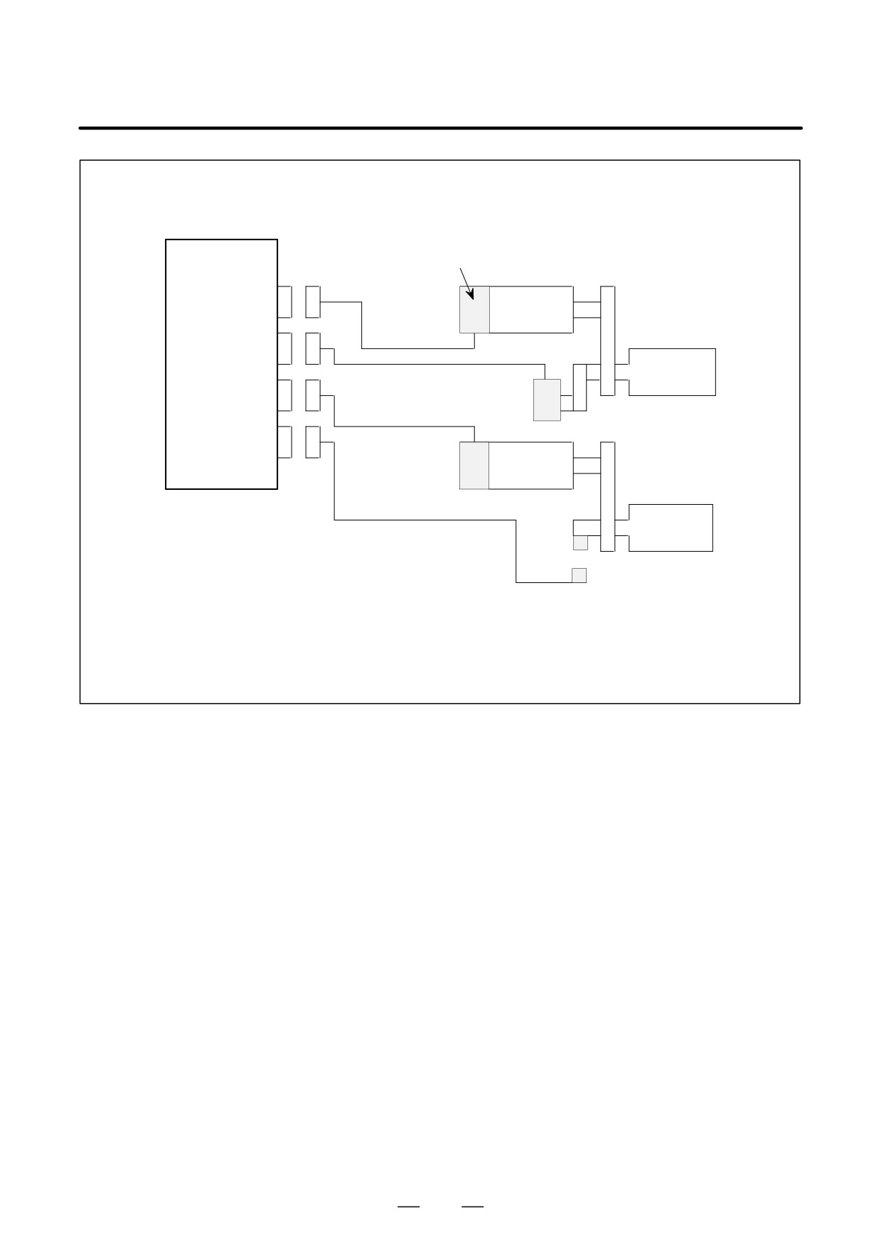
B-65162E/03
9.CONNECTION
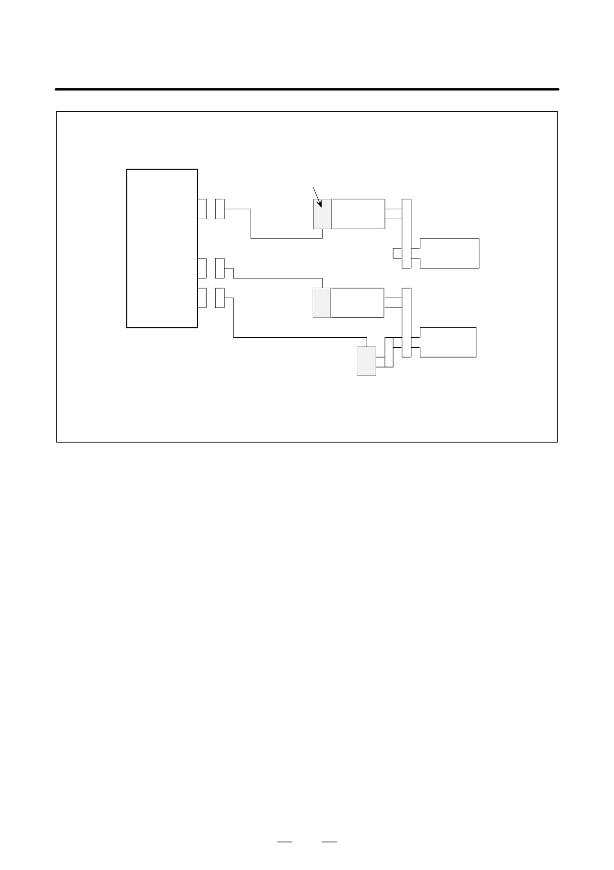
Example 2-5) Using a position coder for the main spindle, the MZ sensor incorporated into the motor,
and an external one-turn signal switch for the subspindle
SPM
M sensor (pulse generator)
TYPE 3
JY2
Spindle
motor
K14
JY4
Main spindle
K16
JY6
Position coder
K14
JY7
MZ sensor
Spindle
(built-in sensor)
motor
K32
Sub spindle
External one-turn
signal switch
(proximity switch)
See 9.2.3 (10) and (11) for a detailed description of the connection of cable K14.
See 9.2.3 (16) for a detailed description of the connection of cable K16.
See 9.2.3 (22) for a detailed description of the connection of cable K32.
315
9. CONNECTION
B-65162E/03
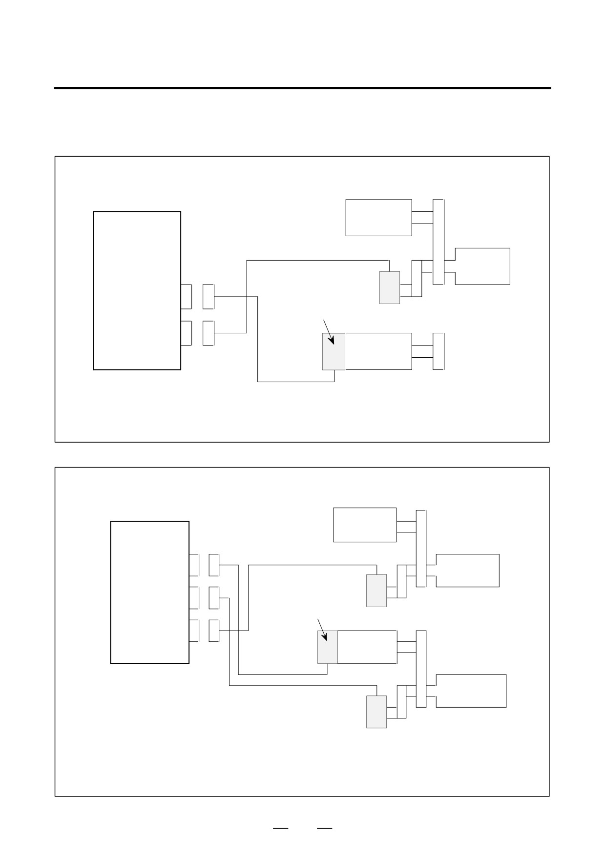
(24) Speed difference control (TYPE 3 only)
Shown below are examples of speed difference control connection.
Example 1) Using a motor incorporating an MZ sensor for the second spindle
SPM
Spindle motor
TYPE 3
K16
First spindle
Position coder
JY2
MZ sensor (built-in sensor)
JY8
Spindle motor
K17
See 9.2.3 (16) for a detailed description of the connection of cable K16.
See 9.2.3 (17) for a detailed description of the connection of cable K17.
Example 2) Using a position coder for the second spindle
Spindle motor
SPM
TYPE 3
K16
JY2
First spindle
JY4
M sensor
(pulse generator)
Position coder
JY8
Spindle motor
K17
K16
Second spindle
Position coder
See 9.2.3 (16) for a detailed description of the connection of cable K16.
See 9.2.3 (10) and (11) for a detailed description of the connection of cable K14.
316
B-65162E/03
9.CONNECTION
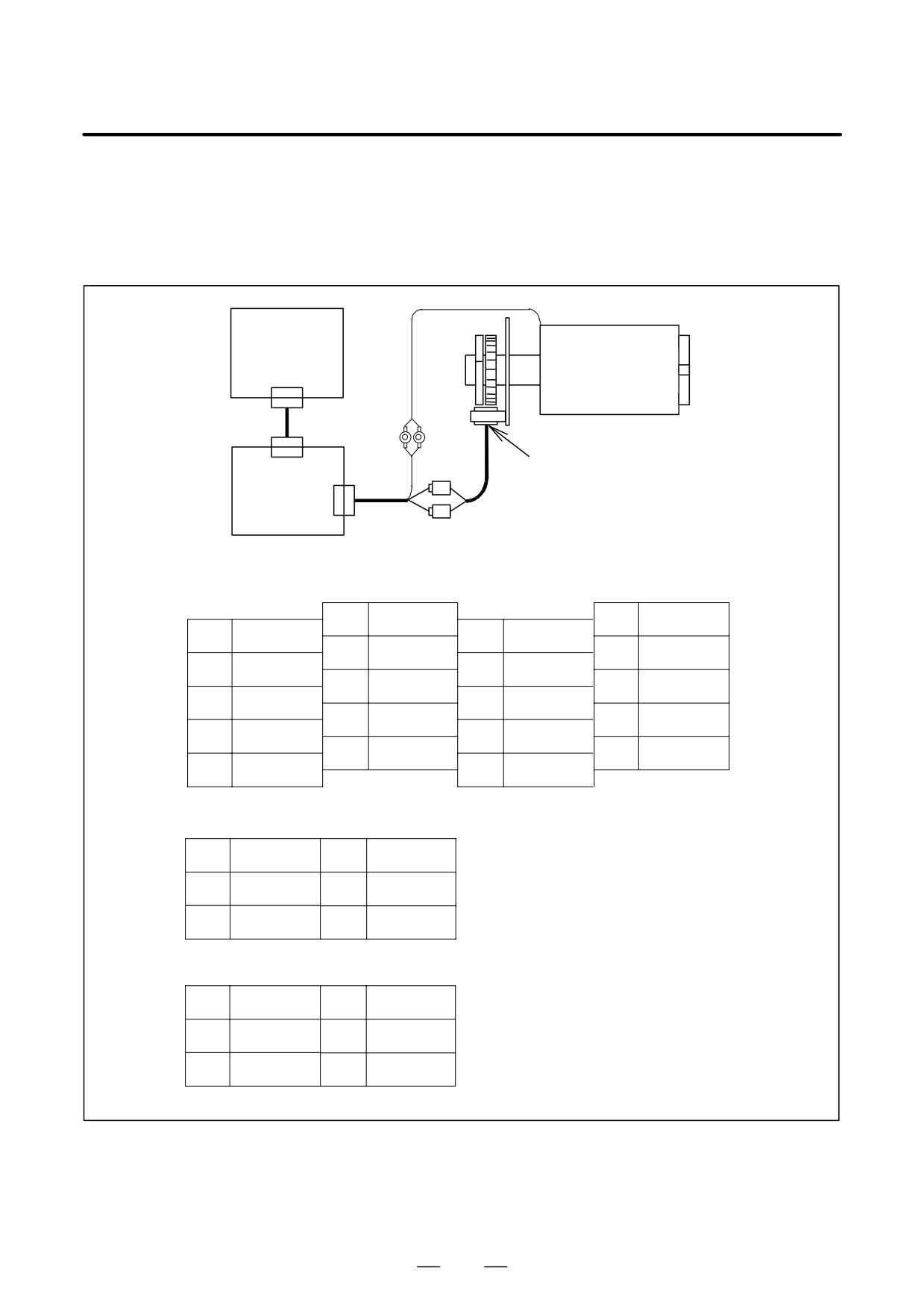
(25) Using the α sensor Cs contour control function
(1) If the spindle-to-motor gear ratio is 1:1
(the spindle is linked directly to the built-in motor or AC spindle
motor)
CNC control unit
Spindle+
OH line
built-in motor
BZ sensor (built-in sensor)
CN1
SPM
K17
TYPE4
CN2
JY5
JY5
10
SS
20
5V
9
+5V
19
8
*PB
18
5V
7
PB
17
6
*PA
16
0V
5
PA
15
OH2
4
14
0V
3
13
OH1
2
*MZ
12
0V
1
MZ
11
CN1
1
*VZ
4
CN1,2
2
*VA
5
VA
HONDA: Connector Z-374
Contact HKP-F413
3
*VB
6
VB
CN2
1
5V
4
5V
JY5
HIROSE: Connector FI40A-20S
2
VZ
5
SS
Housing FI-20-CV5
3
0V
6
0V
317
9. CONNECTION
B-65162E/03
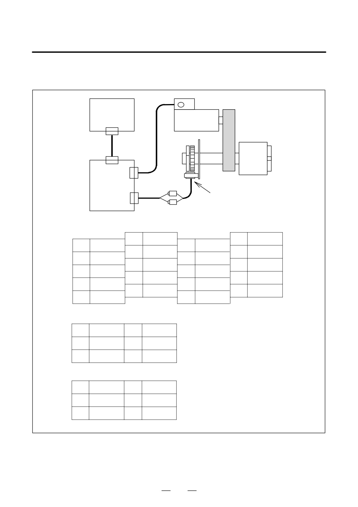
(2) There is a reduction gear ratio between the spindle and motor
(AC spindle motor incorporating MZ sensor + BZ sensor)
AC spindle motor incorporating MZ sensor
CNC control unit
K17
JY2
Spindle
SPM
CN1
TYPE4
K17
BZ sensor (built-in sensor)
CN2
JY5
JY2, JY5
10
SS
20
5V
9
+5V
19
8
*PB
18
5V
7
PB
17
6
*PA
16
0V
5
PA
15
OH2
4
14
0V
3
13
OH1
2
*MZ
12
0V
1
MZ
11
CN1
1
*VZ
4
CN1,2
2
*VA
5
VA
HONDA: Connector Z-374
Contact HKP-F413
3
*VB
6
VB
CN2
1
5V
4
5V
JY2, JY5
HIROSE: Connector FI40A-20S
2
VZ
5
SS
Housing FI-20-CV5
3
0V
6
0V
318
B-65162E/03
9.CONNECTION
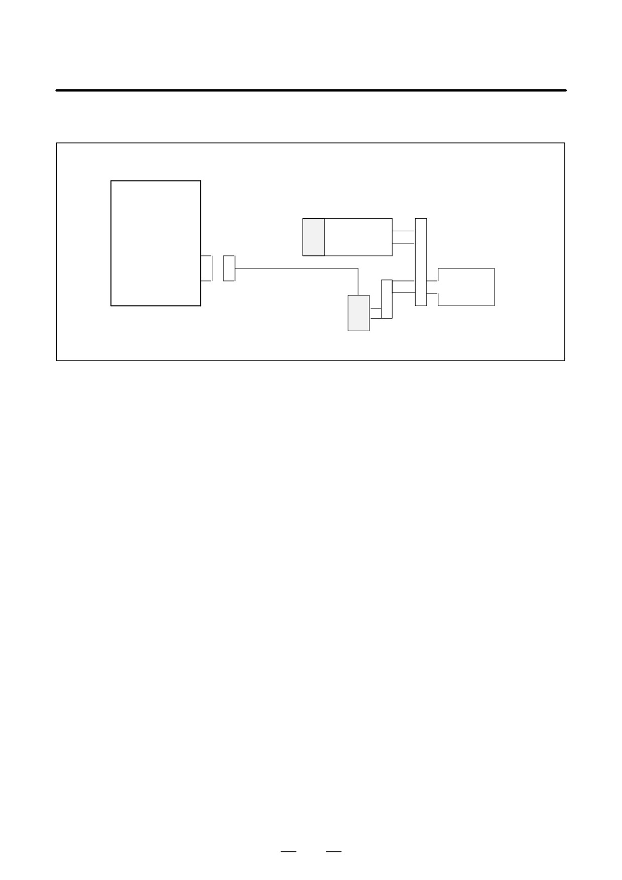
(26) Using a position coder in the SPMC
SPMC
Spindle motor
K16
JY4
Spindle
Position coder
See 9.2.3 (16) for a detailed description of the connection of cable K16.
(27) Spindle Motor Feedback Cable Connection
1) Outline
An error relating to the feedback signal may occur, depending on the
wiring of the connectors in the motor terminal box or the transit box
used for connecting the spindle motor feedback cable. To prevent
such an error from occurring, observe the following:
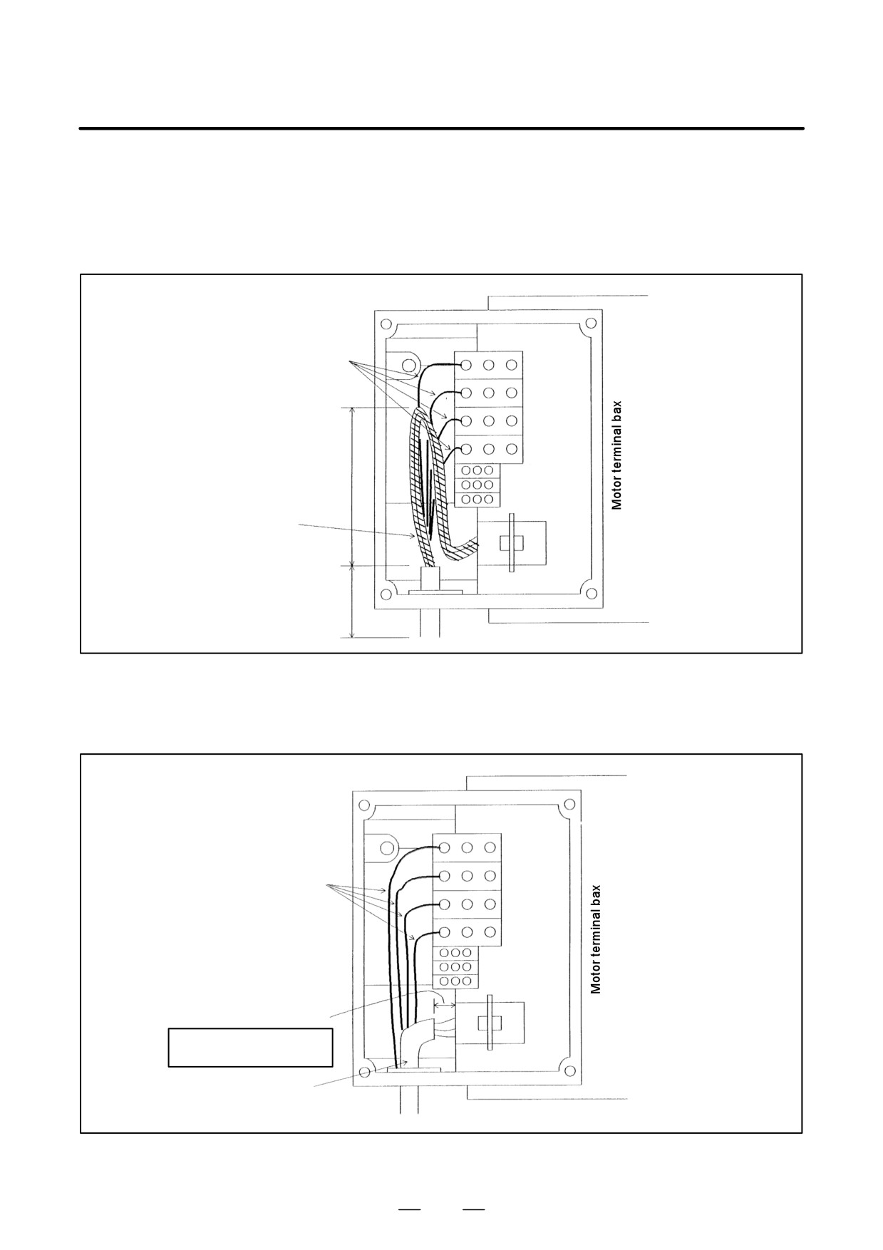
2) Description
(1) Error description
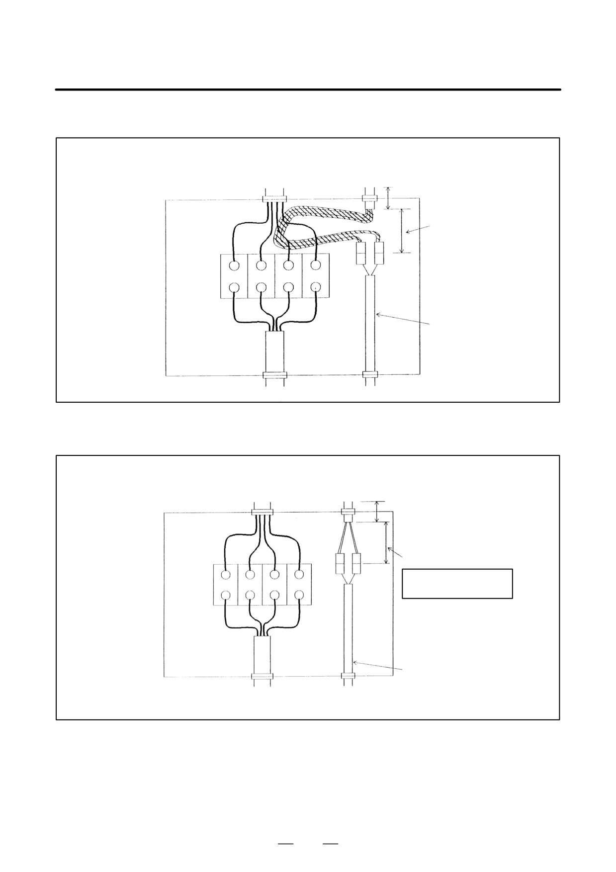
If an unshielded portion of the spindle motor feedback cable is
long and routed close to a power line in the motor terminal box
or transit box, switching of the power transistor may induce noise
in the feedback signal, resulting in the following intermittent
symptoms:
M sensor (Pulse generator) :
Large speed variation at low speed
MZ sensor, BZ sensor (Built-in sensor) :
Large speed variation at low speed
AL-41 (detection error of one-rotation
signal) lights in error
AL-47 (position coder signal error) lights
in error
319
9. CONNECTION
B-65162E/03
(2) Example of wiring likely to cause faults/recommend wiring
method
When the unshielded portion is routed through the motor
terminal box
[Wiring liable to cause errors]
Motor power line
Unshielded
portion (hatched)
AMP
connector
Feed back cable
Shielded portion
Fig.1
[Recommended example]
Motor power lines
AMP
connector
Unshielded portion
Reduce the length
of the unshielded portion.
Feed back cable
Fig.2
320
B-65162E/03
9.CONNECTION
When the unshielded portion is routed through the transit box
[Wiring liable to cause errors]
To amplifier
To amplifier
Shielded portion
Unshielded
portion
(hatched)
Transit box
Transit
connector
Feed back
cable
Motor power line
To motor
To sensor
Fig.3
[Recommended example]
Shielded portion
To amplifier
To amplifier
Transit box
Unshielded portion
Reduce the length of the
Transit
unshielded portion.
connector
Motor
power lines
Feed back cable
To motor
To sensor
Fig.4
321
9. CONNECTION
B-65162E/03
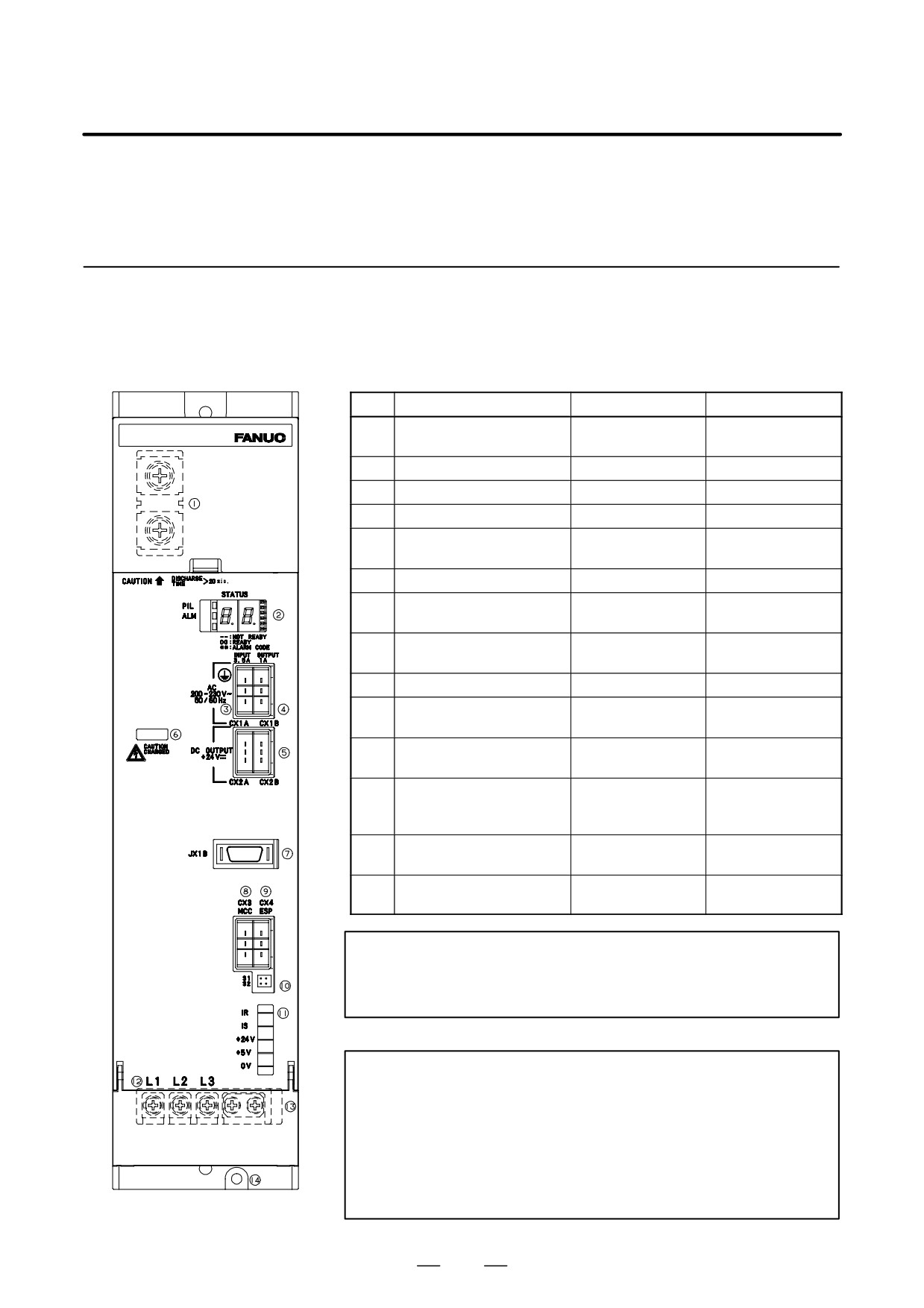
9.3
CONNECTOR
LOCATION
9.3.1
Power Supply Module
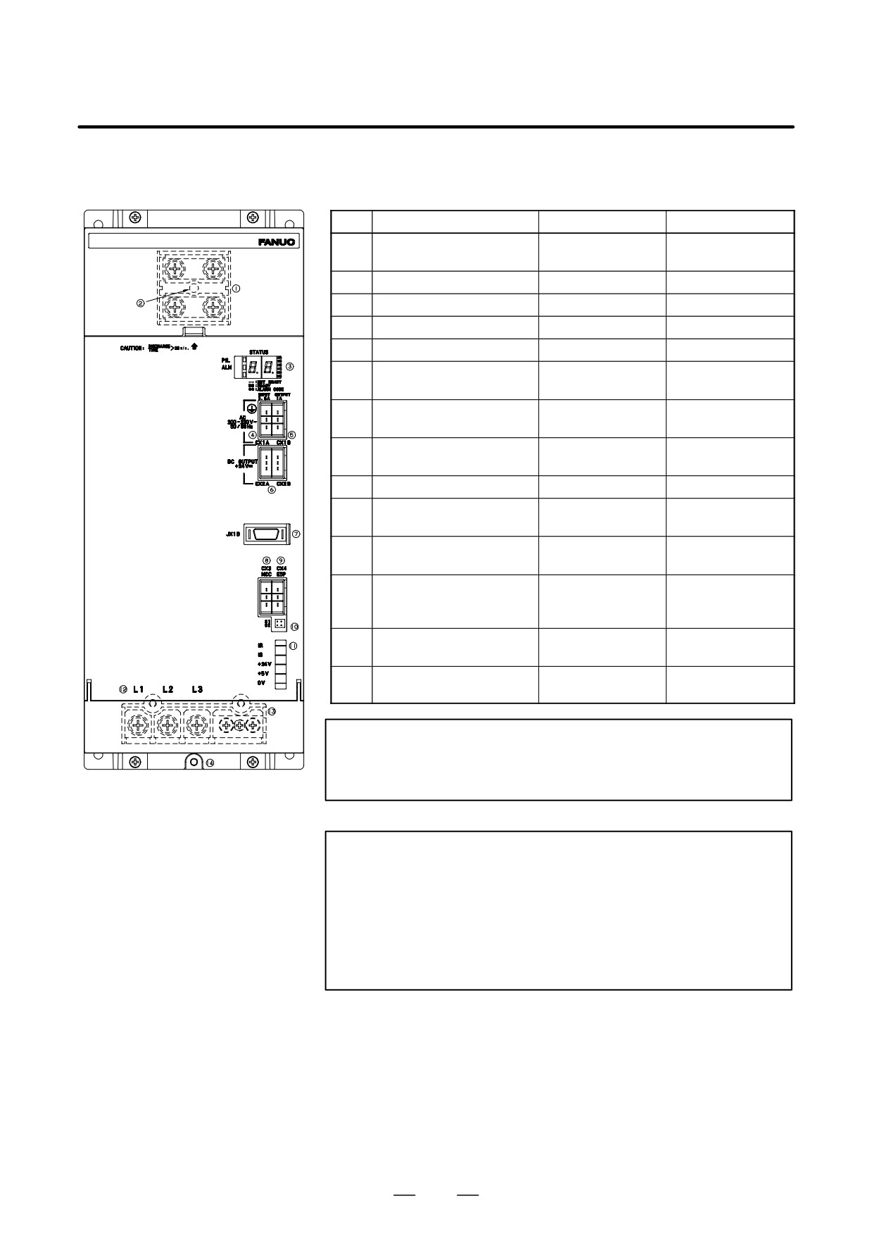
(a) PSM-5.5, PSM-11
Table.9.3.1 (a) Names of connectors and terminal blocks
Names
Display
Remarks
1
DC link terminal block
TB1
Display the terminal
block TB1
2
Status LED
STATUS
3
200VAC input connector
CX1A
4
200VAC output connector
CX1B
5
24VDC output connector
CX2A/CX2B
Both connectors
have same function.
6
DC link charge LED
(Warning)
7
Output connector for inter-
JX1B
face between modules
8
Connector for main power
CX3
MCC control signal
9
Connector for ESP signal
CX4
10
Regeneration phase
S1/S2
Factory-set to S1
switch
11
Check pin
See (Note) for
details
12
Terminal names for termi-
nal block for motor power
line
13
Terminal block for motor
Display the terminal
power line
block TB2
14
Tapped hole for grounding
the flange
WARNING
Do not touch module components or connected cables
while this LED is lit. There is a danger of electric shock.
NOTE
Detailed functions of check pin
IR
: Waveform of R-phase input current
IS
: Waveform of S-phase input current
+24V
:
+24V power supply
+5V
:
+5V power supply
0V
:
0V
322
B-65162E/03
9.CONNECTION
(b)
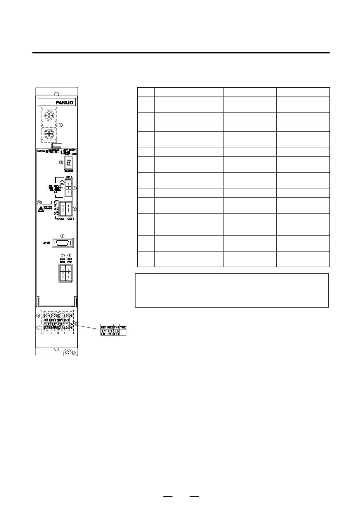
PSM-15, PSM-26, PSM-30,
PSM-37, PSM-18HV, PSM-30HV,
PSM-45HV
Table.9.3.1 (b) Names of connectors and terminal blocks
Names
Display
Remarks
1
DC link terminal block
Display the terminal
block TB1
2
DC link charge LED
(Warning)
3
Status LED
STATUS
4
200VAC input connector
CX1A
5
200VAC output connector
CX1B
6
24VDC output connector
CX2A/CX2B
Both connectors
have same function.
7
Output connector for inter-
JX1B
face between modules
8
Connector for main power
CX3
MCC control signal
9
Connector for ESP signal
CX4
10
Regeneration phase
S1/S2
Factory-set to S1
switch
11
Check pin
See (Note) for
details
12
Terminal names for termi-
nal block for motor power
line
13
Terminal block for motor
TB2
Display the terminal
power line
block TB2
14
Tapped hole for grounding
the flange
WARNING
Do not touch module components or connected cables
while this LED is lit. There is a danger of electric shock.
NOTE
Detailed functions of check pin
IR
: Waveform of R-phase input current
IS
: Waveform of S-phase input current
+24V
:
+24V power supply
+5V
:
+5V power supply
0V
:
0V
323
9. CONNECTION
B-65162E/03
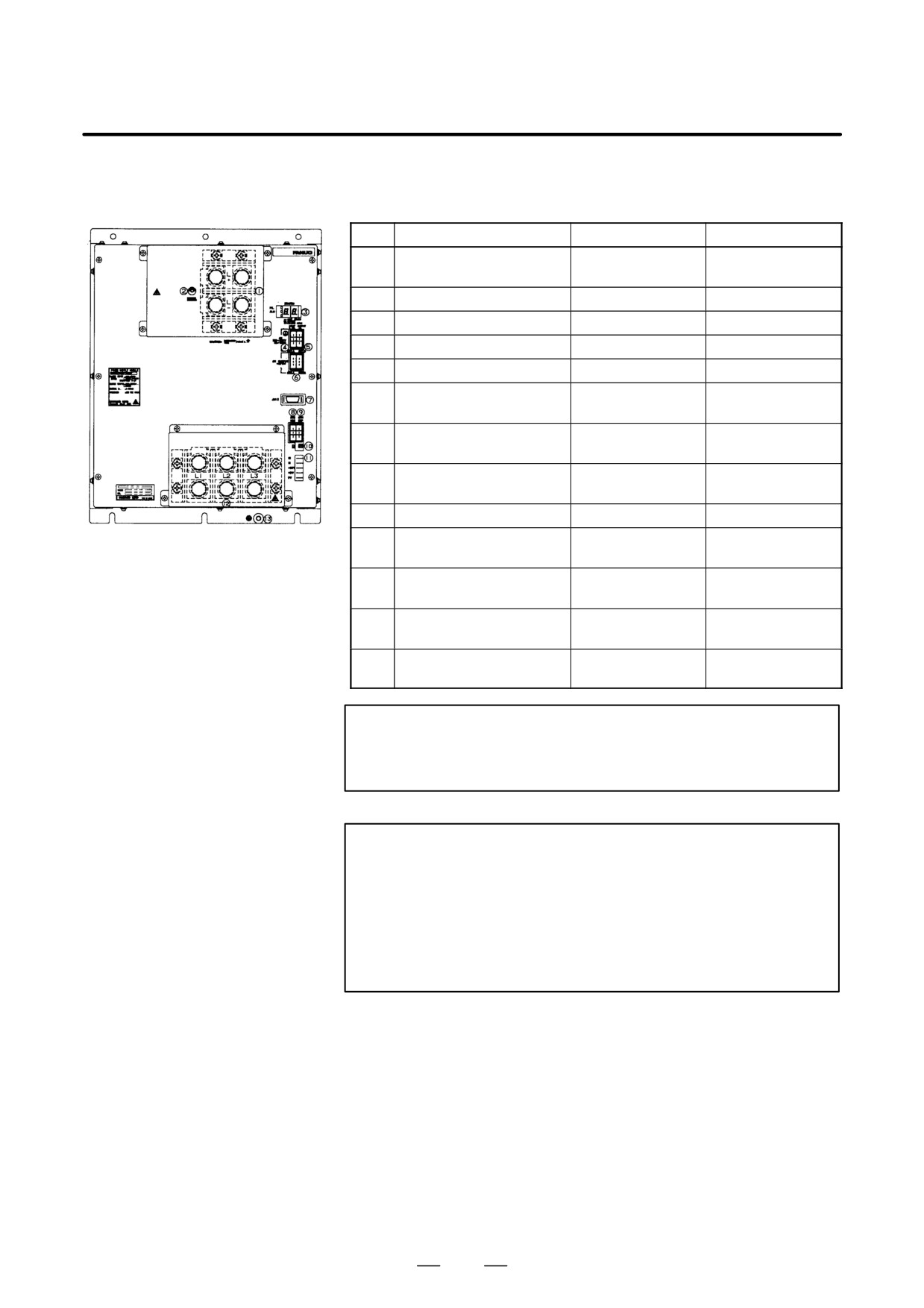
(c) PSMR-3, 5.5
Table.9.3.1 (c) Names of connectors and terminal blocks
Names
Display
Remarks
1
DC link terminal block
Display the terminal
block TB1
2
Status LED
STATUS
3
200VAC input connector
CX1A
4
24VDC output connector
CX2A/CX2B
Both connectors
have same function.
5
DC link charge LED
(Warning)
6
Output connector for inter-
JX1B
face between modules
7
Connector for main power
CX3
MCC control signal
8
Connector for ESP signal
CX4
9
Terminal block, Terminal
names
10
Terminal for separate type
Display the terminal
regenerative resistor con-
block TB2
nection
11
Terminal for main power
Display the terminal
supply connection
block TB2
12
Tapped hole for grounding
the flange
WARNING
Do not touch module components or connected cables
while this LED is lit. There is a danger of electric shock.
324
B-65162E/03
9.CONNECTION
(d)
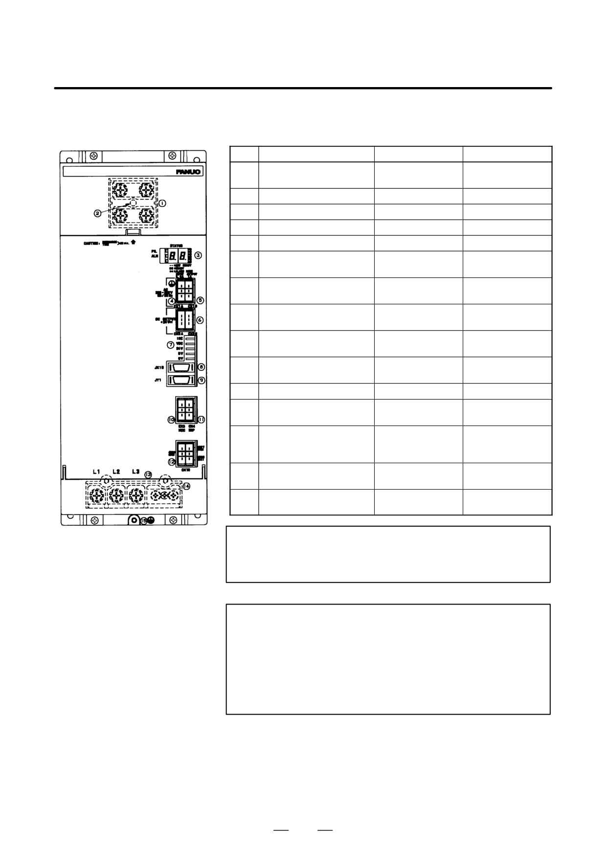
PSM-45, PSM-75HV
Table.9.3.1 (d) Connector and Terminal Board Names
Names
Display
Remarks
1
DC link terminal block
Display the terminal
block TB1
2
DC link charge LED
(Warning)
3
Status LED
STATUS
4
200VAC input connector
CX1A
5
200VAC output connector
CX1B
6
24VDC output connector
CX2A/CX2B
Both connectors
have same function.
7
Output connector for inter-
JX1B
face between modules
8
Connector for main power
CX3
MCC control signal
9
Connector for ESP signal
CX4
10
Regeneration phase
S1/S2
Factory-set to S1
switch
11
Check pin
See (Note) for
details
12
Terminal block for motor
Display the terminal
power line
block TB2
13
Tapped hole for grounding
the flange
WARNING
Do not touch module components or connected cables
while this LED is lit. There is a danger of electric shock.
NOTE
Detailed functions of check pin
IR
: Waveform of R-phase input current
IS
: Waveform of S-phase input current
+24V
:
+24V power supply
+5V
:
+5V power supply
0V
:
0V
325
9. CONNECTION
B-65162E/03
(e)
PSMV-11HV
Table.9.3.1 (e) Connector and Terminal Board Names
Names
Display
Remarks
1
DC link terminal block
Display the terminal
block TB1
2
DC link charge LED
(Warning)
3
Status LED
STATUS
4
200VAC input connector
CX1A
5
200VAC output connector
CX1B
6
24VDC output connector
CX2A/CX2B
Both connectors
have same function.
7
Check pin
See (Note) for
details
8
Output connector for inter-
JX1B
face between modules
9
Connector for test by FA-
JY1
NUC
10
Connector for main power
CX3
MCC control signal
11
Connector for ESP signal
CX4
12
Connector for phase detec-
CX10
tion signal
13
Terminal names for termi-
nal block for motor power
line
14
Terminal block for motor
Display the terminal
power line
block TB2
15
Tapped hole for grounding
the flange
WARNING
Do not touch module components or connected cables
while this LED is lit. There is a danger of electric shock.
NOTE
Detailed functions of check pin
IDC
: DC link current waveform
VDC
: DC link voltage waveform
+24V
:
+24V power supply
+5V
:
+5V power supply
0V
:
0V
326
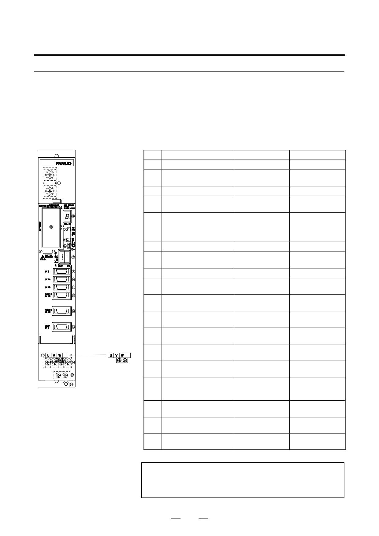
B-65162E/03
9.CONNECTION
9.3.2
Servo Amplifier Module
1.
TYPE A, TYPE B Interface
(a)
SVM1-12, SVM1-20, SVM1-40S,
SVM1-40L,SVM1-80
Table.9.3.2 (a) Names of connectors and terminal blocks
Names
Display
Remarks
1
DC link terminal block
M6
2
Battery for ABS pulse cod-
BATTERY
A06B-6073-K001
er
3
Status LED
STATUS
4
Power connector for ABS
CX5X
pulse coder battery
5
Interface switching con-
S1/S2
Type-A interface:
nector
S1
Type-B interface:
S2
6
Fuse for 24V power
F2
7
24V power I/O connector
CX2A/CX2B
Both connectors
have same function.
8
DC link charge LED
(Warning)
9
Signal check connector
JX5
Use an SVM check
board.
10
Input connector for inter-
JX1A
face between modules
11
Output connector for inter-
JX1B
face between modules
12
NC interface connector for
PWM11/JV1B
FS16, FS18, FS15,
type-A interface
FS0, etc.
13
NC interface connector for
PWM21/JS1B
FS20, FS21-G, etc.
type-B interface
14
Pulse coder connector
ENC1/JF1
Only for type-B in-
terface
15
Terminal names for termi-
nal block for motor power
line
16
Terminal block for motor
Display the terminal
power line
block TB2
17
Earth plate
Attatched to amplifi-
er
18
Tapped hole for grounding
the flange
WARNING
Do not touch module components or connected cables
while this LED is lit. There is a danger of electric shock.
327
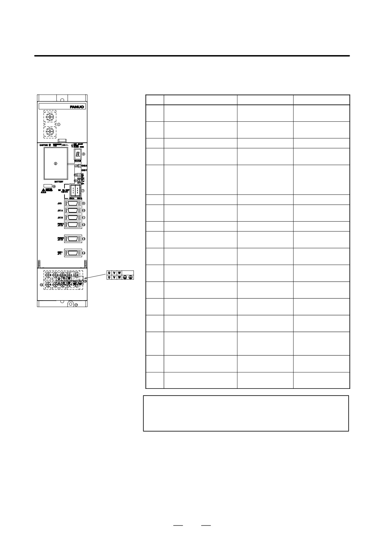
9. CONNECTION
B-65162E/03
(b)
SVM1-130
Table.9.3.2 (b) Names of connectors and terminal blocks
Names
Display
Remarks
1
DC link terminal block
Display the terminal
block TB2
2
Battery for ABS pulse cod-
BATTERY
A06B-6073-K001
er
3
Status LED
STATUS
4
Power connector for ABS
CX5X
pulse coder battery
5
Interface switching con-
S1/S2
Type-A interface:
nector
S1
Type-B interface:
S2
6
Fuse for 24V power
F2
3.2A, 48VDC
7
24V power I/O connector
CX2A/CX2B
Both connectors
have same function.
8
DC link charge LED
(Warning)
9
Signal check connector
JX5
Use an SVM check
board.
10
Input connector for inter-
JX1A
face between modules
11
Output connector for inter-
JX1B
face between modules
12
NC interface connector for
PWM11/JV1B
FS16, FS18, FS15,
type-A interface
FS0, etc.
13
NC interface connector for
PWM21/JS1B
FS20, FS21-G, etc.
type-B interface
14
Pulse coder connector
ENC1/JF1
Only for type-B in-
terface
15
Terminal names for termi-
nal block for motor power
line
16
Terminal block for motor
Display the terminal
power line
block TB2
17
Tapped hole for grounding
the flange
WARNING
Do not touch module components or connected cables
while this LED is lit. There is a danger of electric shock.
328
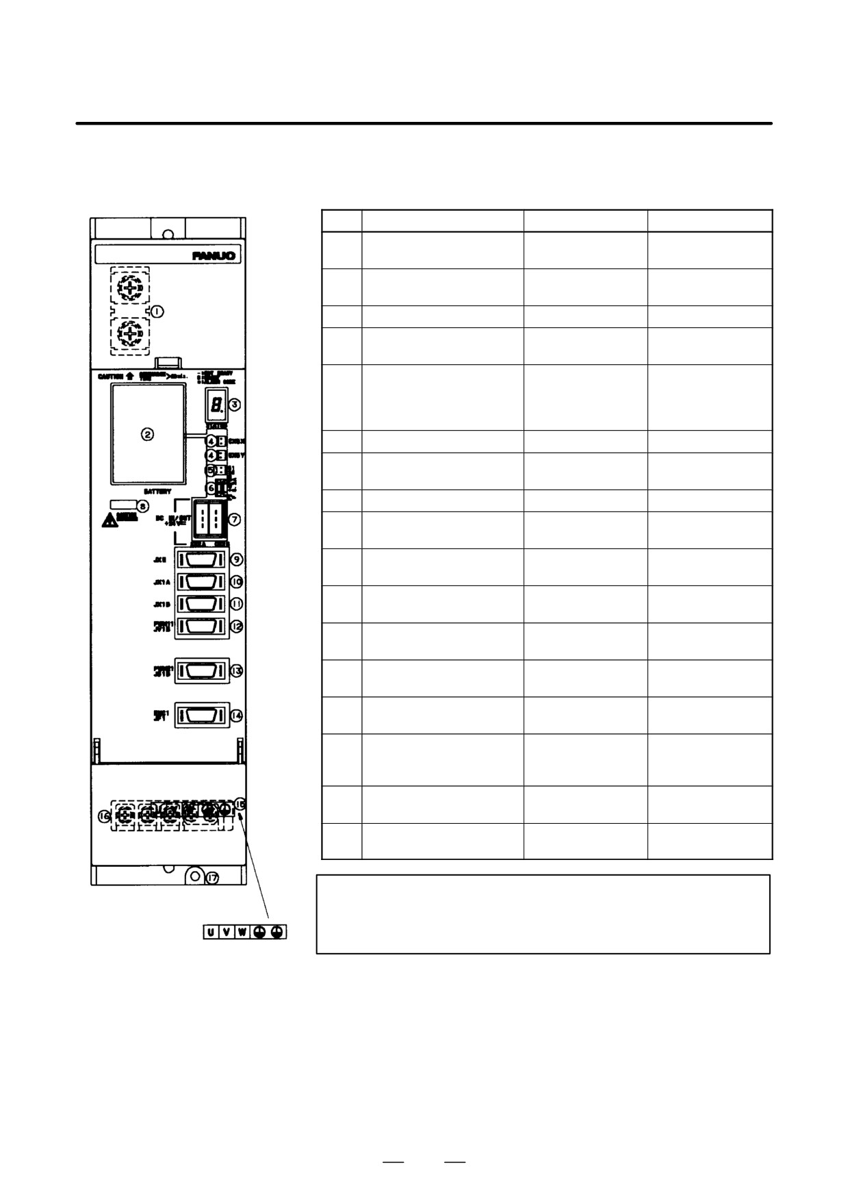
B-65162E/03
9.CONNECTION
(c)
SVM1-130, SVM1-20HV,
SVM1-40HV, SVM1-60HV
Table.9.3.2 (c) Connector and Terminal Board Names
Names
Display
Remarks
1
DC link terminal block
Display the terminal
block TB2
2
Battery for ABS pulse cod-
BATTERY
A06B-6073-K001
er
3
Status LED
STATUS
4
Power connector for ABS
CX5X
pulse coder battery
5
Interface switching con-
S1/S2
Type-A interface:
nector
S1
Type-B interface:
S2
6
Fuse for 24V power
F2
3.2A, 48VDC
7
24V power I/O connector
CX2A/CX2B
Both connectors
have same function.
8
DC link charge LED
(Warning)
9
Signal check connector
JX5
Use an SVM check
board.
10
Input connector for inter-
JX1A
face between modules
11
Output connector for inter-
JX1B
face between modules
12
NC interface connector for
PWM11/JV1B
FS16, FS18, FS15,
type-A interface
FS0, etc.
13
NC interface connector for
PWM21/JS1B
FS20, FS21-G, etc.
type-B interface
14
Pulse coder connector
ENC1/JF1
Only for type-B in-
terface
15
Terminal names for termi-
nal block for motor power
line
16
Terminal block for motor
Display the terminal
power line
block TB2
17
Tapped hole for grounding
the flange
WARNING
Do not touch module components or connected cables
while this LED is lit. There is a danger of electric shock.
329
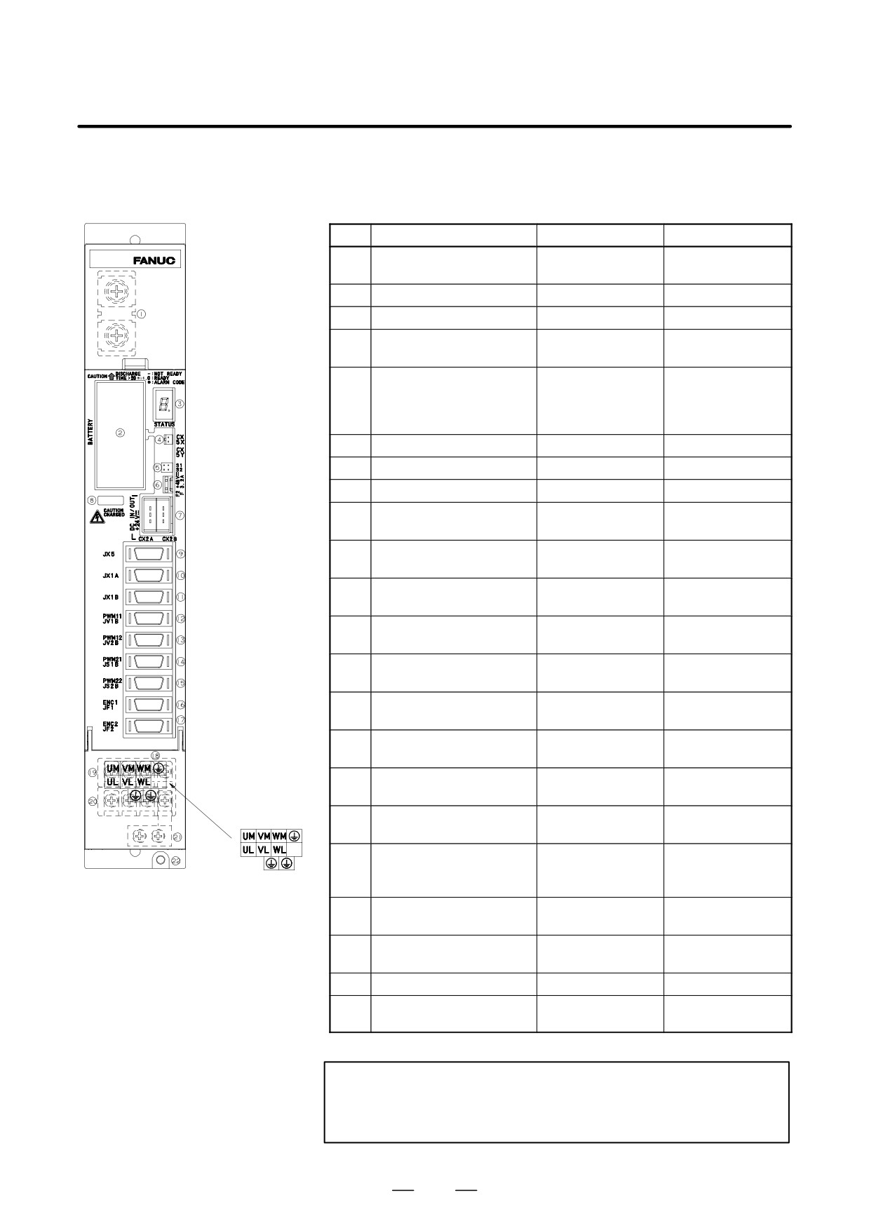
9. CONNECTION
B-65162E/03
(d)
SVM2-12/12, SVM2-12/20,
SVM2-20/20,SVM2-12/40,
SVM2-20/40, SVM2-40/40
Table.9.3.2 (d) Names of connectors and terminal blocks
Names
Display
Remarks
1
DC link terminal block
Display the terminal
block TB2
2
Battery for ABS pulse coder
BATTERY
A60B-6073-K001
3
Status LED
STATUS
4
Power connector for ABS
CX5X
pulse coder battery
5
Interface switching con-
S1/S2
Type-A interface:
nector
S1
Type-B interface:
S2
6
Fuse for 24V power
F2
3.2A, 48VDC
7
24V power I/O connector
CX2A/CX2B
8
DC link charge LED
(Warning)
9
Signal check connector
JX5
Use an SVM check
board.
10
Input connector for inter-
JX1A
face between modules
11
Output connector for inter-
JX1B
face between modules
12
NC interface connector : L
PWM11/JV1B
FS16,FS18,FS15,F
axis for type-A interface
S0,etc
13
NC interface connector : M
PWM12/JV2B
FS16, FS18, FS15,
axis for type-A interface
FS0, etc
14
NC interface connector : L
PWM21/JS1B
FS20, FS21-G, etc.
axis for type-B interface
15
NC interface connector : M
PWM22/JS2B
FS20, FS21-G, etc.
axis for type-B interface
16
Pulse coder connector : L
ENC1/JF1
Only for type-B in-
axis
terface
17
Pulse coder connector : M
ENC2/JF2
Only for type-B in-
axis
terface
18
Terminal names for termi-
nal block for motor power
line
19
Terminal block for motor
Display the terminal
power line : M axis
block TB2
20
Terminal block for motor
Display the terminal
power line : L axis
block TB2
21
Earth plate
Attatched to amplifier
22
Tapped hole for grounding
the flange
WARNING
Do not touch module components or connected cables
while this LED is lit. There is a danger of electric shock.
330
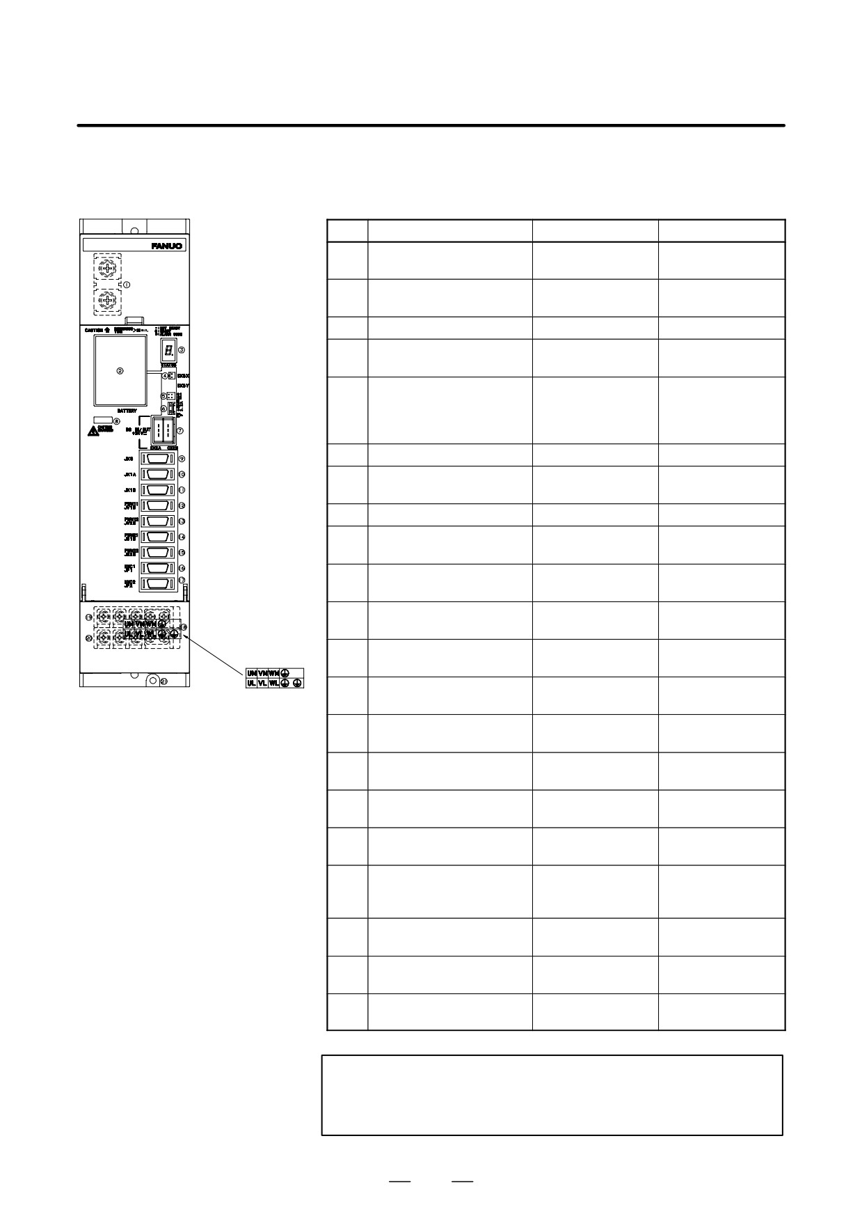
B-65162E/03
9.CONNECTION
(e)
SVM2-40/80, SVM2-80/80,
SVM2-20/20HV, SVM2-20/40HV,
SVM2-20/60HV, SVM2-40/40HV,
SVM2-40/60HV, SVM2-60/60HV
Table.9.3.2 (e) Names of connectors and terminal blocks
Names
Display
Remarks
1
DC link terminal block
Display the terminal
block TB2
2
Battery for ABS pulse cod-
BATTERY
A06B-6073-K001
er
3
Status LED
STATUS
4
Power connector for ABS
CX5X
pulse coder battery
5
Interface switching con-
S1/S2
Type-A interface:
nector
S1
Type-B interface:
S2
6
Fuse for 24V power
F2
32A, 48VDC
7
24V power I/O connector
CX2A/CX2B
Both connectors
have same function.
8
DC link charge LED
(Warning)
9
Signal check connector
JX5
Use an SVM check
board.
10
Input connector for inter-
JX1A
face between modules
11
Output connector for inter-
JX1B
face between modules
12
NC interface connector : L
PWM11/JV1B
FS16, FS18, FS15,
axis for type-A interface
FS0, etc
13
NC interface connector : M
PWM12/JV2B
FS16, FS18, FS15,
axis for type-A interface
FS0, etc
14
NC interface connector : L
PWM21/JS1B
FS20, FS21-G, etc.
axis for type-B interface
15
NC interface connector : M
PWM22/JS2B
FS20, FS21-G, etc.
axis for type-B interface
16
Pulse coder connector : L
ENC1/JF1
Only for type-B in-
axis
terface
17
Pulse coder connector : M
ENC2/JF2
Only for type-B in-
axis
terface
18
Terminal names for termi-
nal block for motor power
line
19
Terminal block for motor
Display the terminal
power line : M axis
block TB2
20
Terminal block for motor
Display the terminal
power line : L axis
block TB2
21
Tapped hole for grounding
the flange
WARNING
Do not touch module components or connected cables
while this LED is lit. There is a danger of electric shock.
331
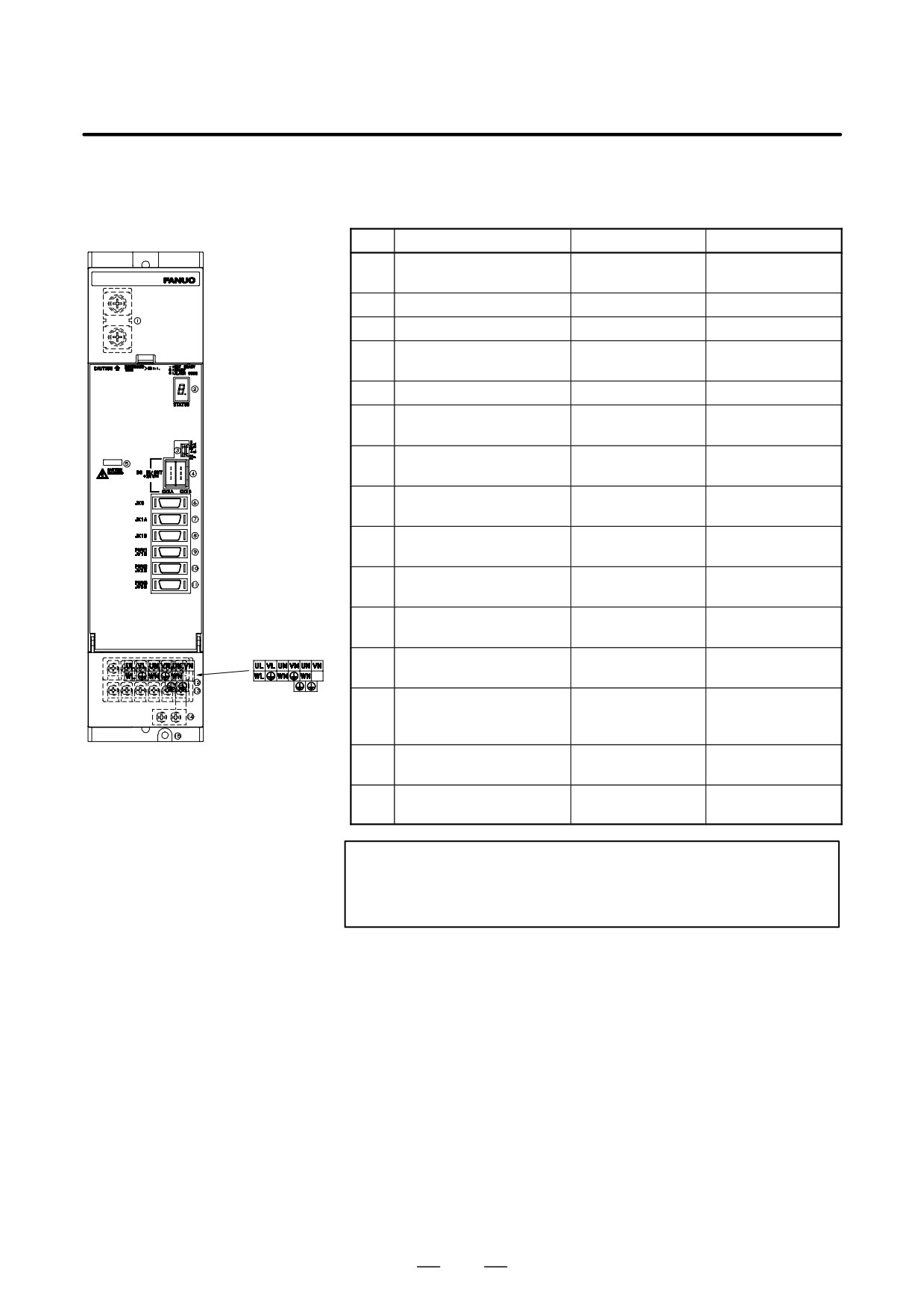
9. CONNECTION
B-65162E/03
(f) SVM3-12/12/12,SVM3-12/12/20,
SVM3-12/20/20, SVM3-20/20/20,
SVM3-12/12/40 SVM3-12/20/40,
Table.9.3.2 (f) Names of connectors and terminal blocks
SVM3-20/20/40
(f)-1 TYPE A
Names
Display
Remarks
1
DC link terminal block
Display the terminal
block TB1
2
Status LED
STATUS
3
Fuse for 24V power
F2
3.2A, 48VDC
4
24V power I/O connector
CX2A/CX2B
Both connectors
have same function.
5
DC link charge LED
(Warning)
6
Signal check connector
JX5
Use an SVM check
board.
7
Input connector for inter-
JX1A
face between modules
8
Output connector for inter-
JX1B
face between modules
9
NC interface connector : L
PWM1/JV1B
axis for type-A interface
10
NC interface connector : M
PWM2/JV2B
axis for type-A interface
11
NC interface connector : N
PWM3/JV3B
axis for type-A interface
12
Terminal block for motor
power line
13
Terminal names for termi-
Display the terminal
nal block for motor power
block TB2
line
14
Earth plate
Attatched tp amplifi-
er
15
Tapped hole for grounding
the flange
WARNING
Do not touch module components or connected cables
while this LED is lit. There is a danger of electric shock.
332