FANUC SERVO AMPLIFIER a series. DESCRIPTIONS (B-65162E/03) - page 9
B-65162E/03
9.CONNECTION
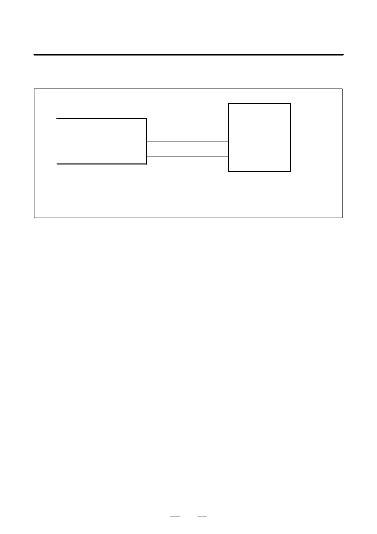
(11) Detailed description of the connection of cable K57
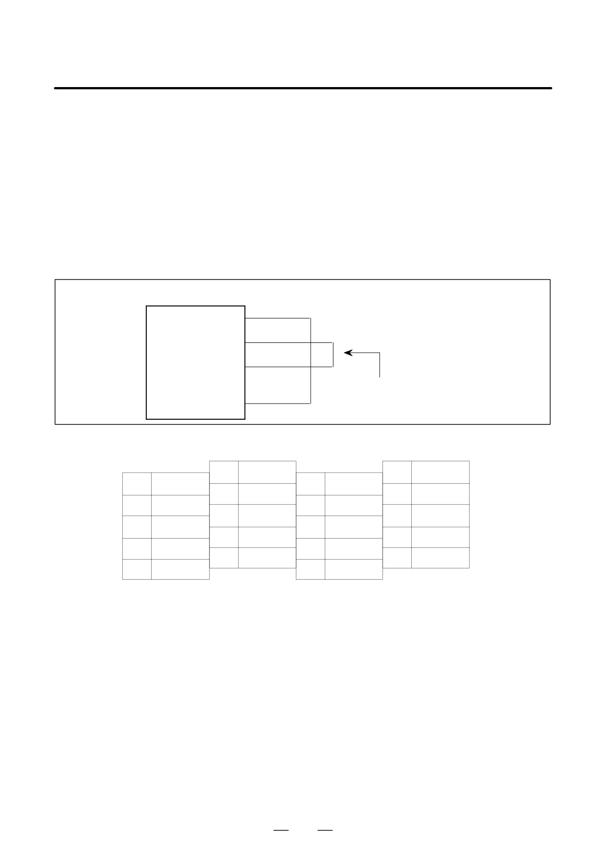
Cable K57 is used to feed a phase detection signal to the PSMV-HV.
PSMV
CX10
AC reactor unit (terminal screw: M4)
(A1)
400R
Phase detection signal
400S
(A2)
400T
(A3)
350/YY
Cable specification: Three-conductor polyvinyl heavy-duty power cable (JIS C3312),
conductor size of 1.25 mm2 (50/0.18),
PVC sheath 10.5 mm in diameter
Connector specification: AMP connector with receptacle housing 2-178129-6 and
receptacle contact 1-175218-2
243
9. CONNECTION
B-65162E/03
9.2.2
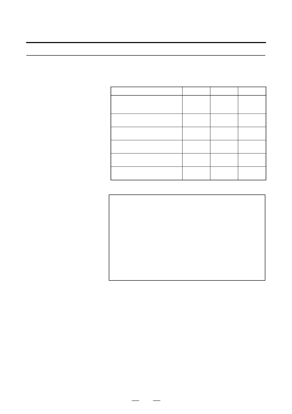
Three different types of interfaces (TYPE A, TYPE B, and FSSB) are
available for servo amplifier modules. First determine which type of
Servo Amplifier Module
interface is used in the CNC unit, then select a servo amplifier module that
Connection Diagram
matches the interface type.
Model/drawing number
TYPE A
TYPE B
FSSB
SVM1, SVM2
A06B-6079-H1VV
f
f
A06B-6079-H2VV
SVM3
f
A06B-6079-H3VV
SVM3
f
A06B-6080-H3VV
SVM1-HV, SVM2-HV
f
f
A06B-6085-HVVV
SVM1, SVM2, SVM3
f
A06B-6096-HVVV
SVM1-HV, SVM2-HV
f
A06B-6097-HVVV
f : Supported
: Not supported
NOTE
1
The A06B-6079-H jjj (excluding the SVM3) and the
A06B-6085-H jjj have two interfaces (TYPE A and
TYPE B). Either can be selected, using interface switching
connector S1/S2 on the front of the servo amplifier modules.
TYPE A interface
: S1
TYPE B interface
: S2
2
The drawing number of the SVM3 (three-axes servo
amplifier module) varies according to the interface it
supports.
TYPE A interface
: A06B-6079-H3jj
TYPE B interface
: A06B-6080-H3jj
FSSB interface
: A06B-6096-H3jj
244
B-65162E/03
9.CONNECTION
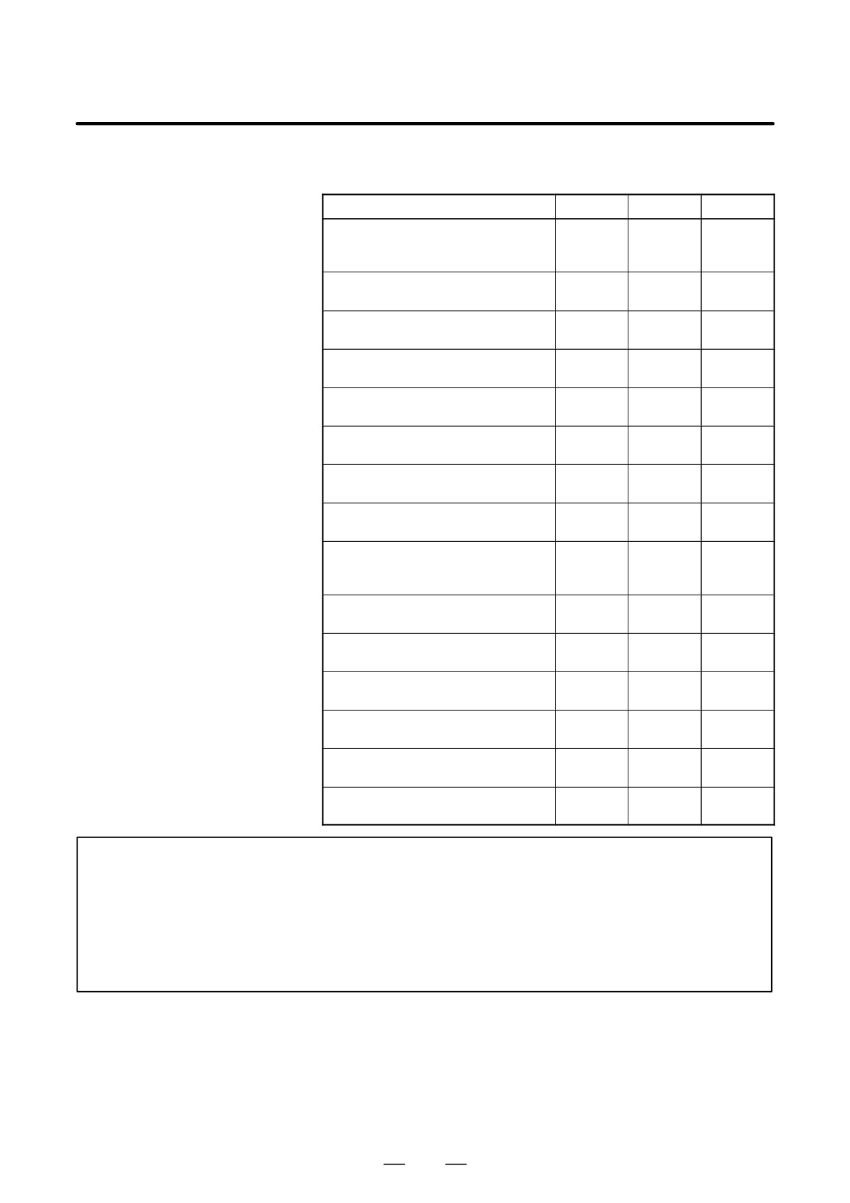
For an explanation of how to connect each model, see the corresponding
description, below.
Model/drawing number
TYPE A
TYPE B
FSSB
SVM1
(excluding the SVM1-240 and -360)
(A)
(B)
---
A06B-6079-H1VV
SVM1-240, SVM1-360
(A), (D)
(B), (D)
---
A06B-6079-H107, H108
SVM1-240 (two of which are used)
(A), (E)
(B), (E)
A06B-6079-H107
SVM2
(A)
(B)
---
A06B-6079-H2VV
SVM3
(A)
---
---
A06B-6079-H3VV
SVM3
---
(B)
---
A06B-6080-H3VV
SVM1-HV
(A)
(B)
---
A06B-6085-H1VV
SVM2-HV
(A)
(B)
---
A06B-6085-H2VV
SVM1
(excluding the SVM1-240 and -360)
---
---
(C)
A06B-6096-H1VV
SVM1-240, SVM1-360
---
---
(D)
A06B-6096-H107, H108
SVM1-240 (two of which are used)
---
---
(E)
A06B-6096-H107
SVM2
---
---
(C)
A06B-6096-H2VV
SVM3
---
---
(C)
A06B-6096-H3VV
SVM1-HV
---
---
(C)
A06B-6097-H1VV
SVM2-HV
---
---
(C)
A06B-6097-H2VV
NOTE
Items (A) to (E) are described on the following pages.
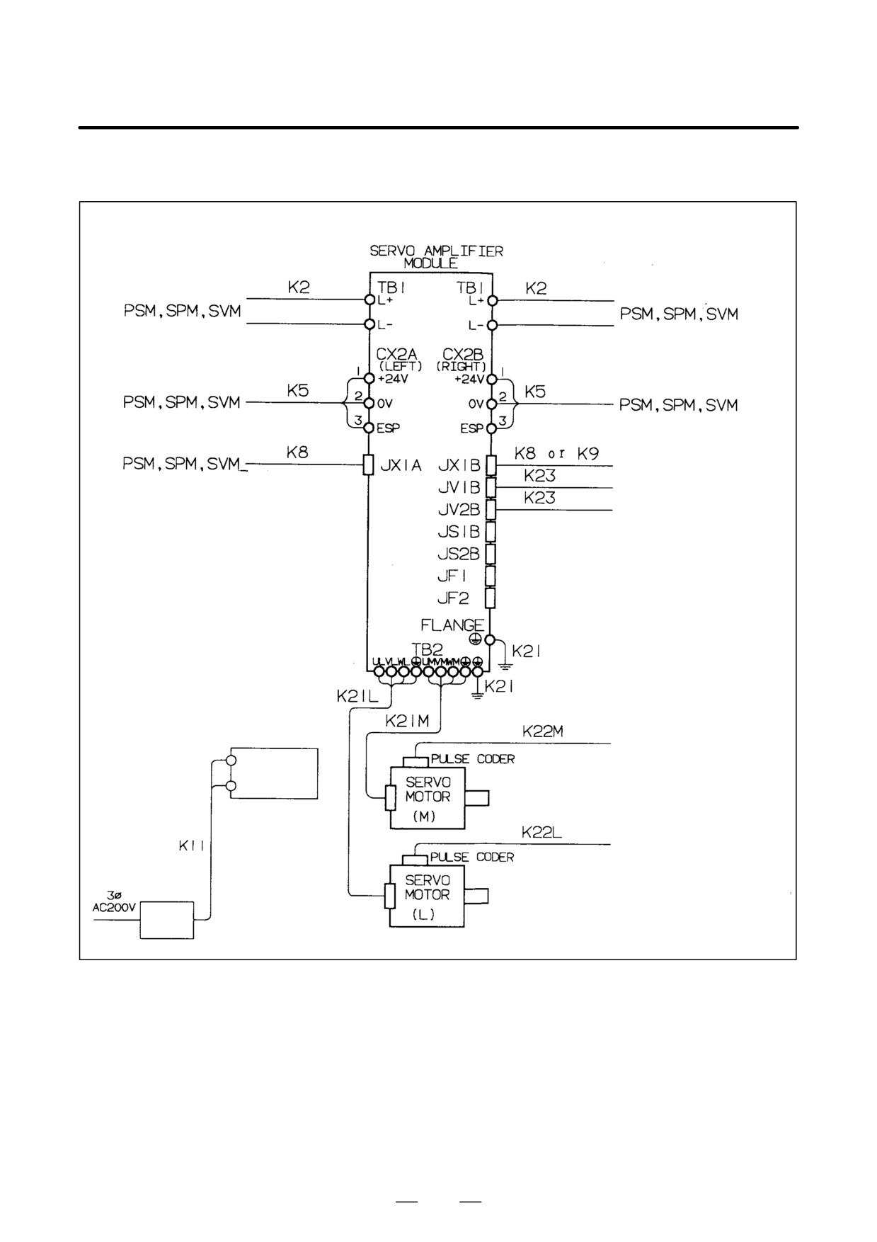
(A) TYPE A interface
(Example: SVM2)
(B) TYPE B interface
(Example: SVM2)
(C) FSSB interface
(Example: SVM2)
(D) FSSB interface
(Example: SVM1-240 and -360)
(E) FSSB interface
(Example: Two SVM1-240 units are used.)
245
9. CONNECTION
B-65162E/03
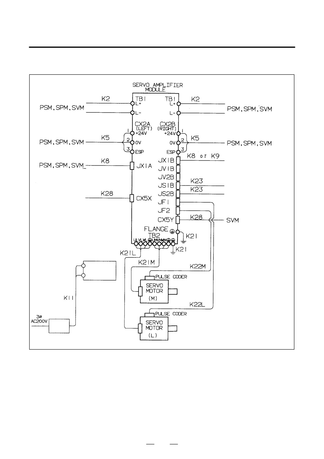
(A) TYPE A interface (Example: SVM2)
SPM, SVM /
Terminating connector
CNC unit
CNC unit
CNC unit
Cooling fan
For the
SVM1-130 only
CNC unit
Circuit
breaker 2
246
B-65162E/03
9.CONNECTION
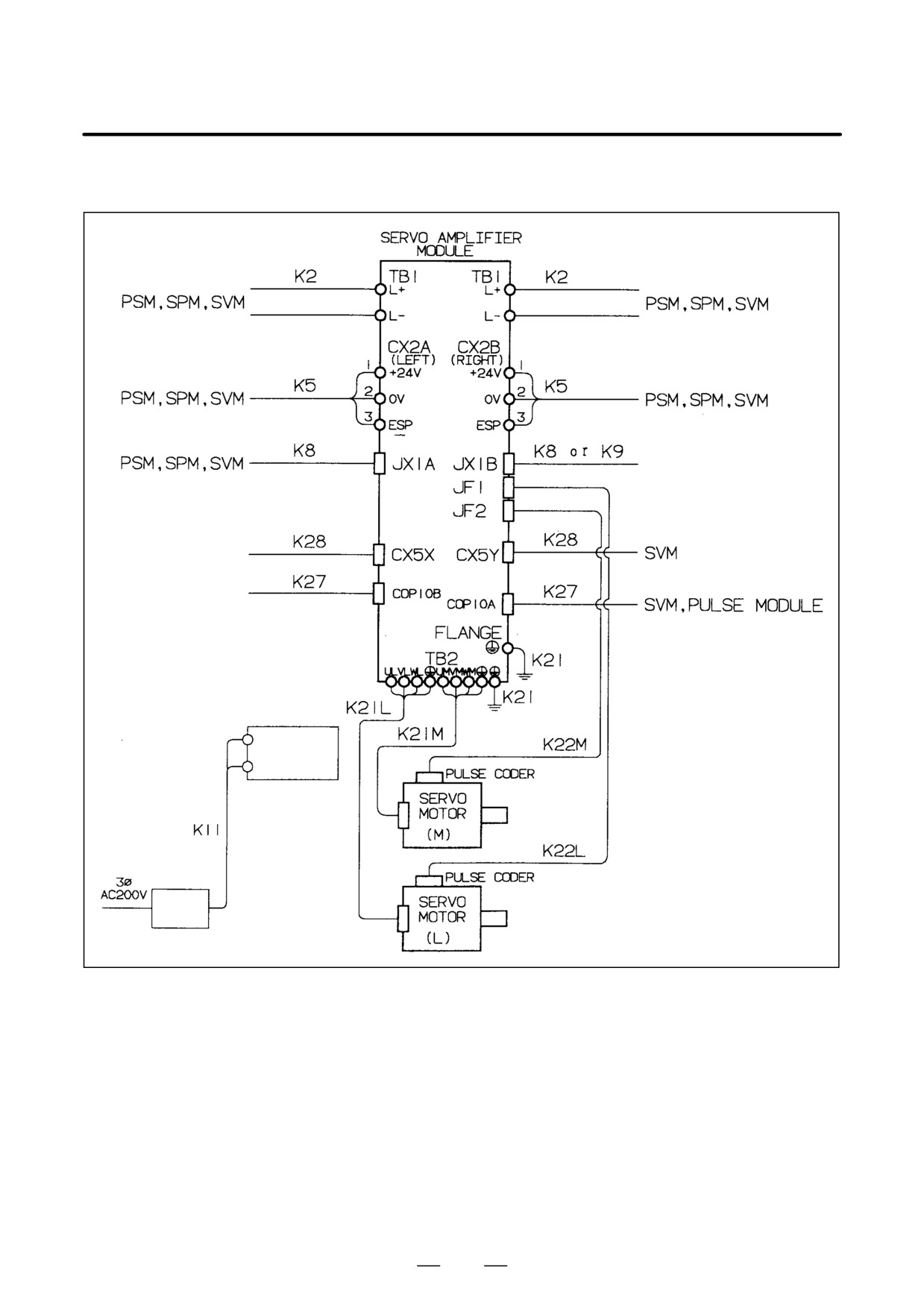
(B) TYPE B interface (Example: SVM2)
SPM, SVM /
Terminating connector
CNC unit
CNC unit
Battery unit, SVM
Cooling fan
For the
SVM1-130 only
Circuit
breaker 2
247
9. CONNECTION
B-65162E/03
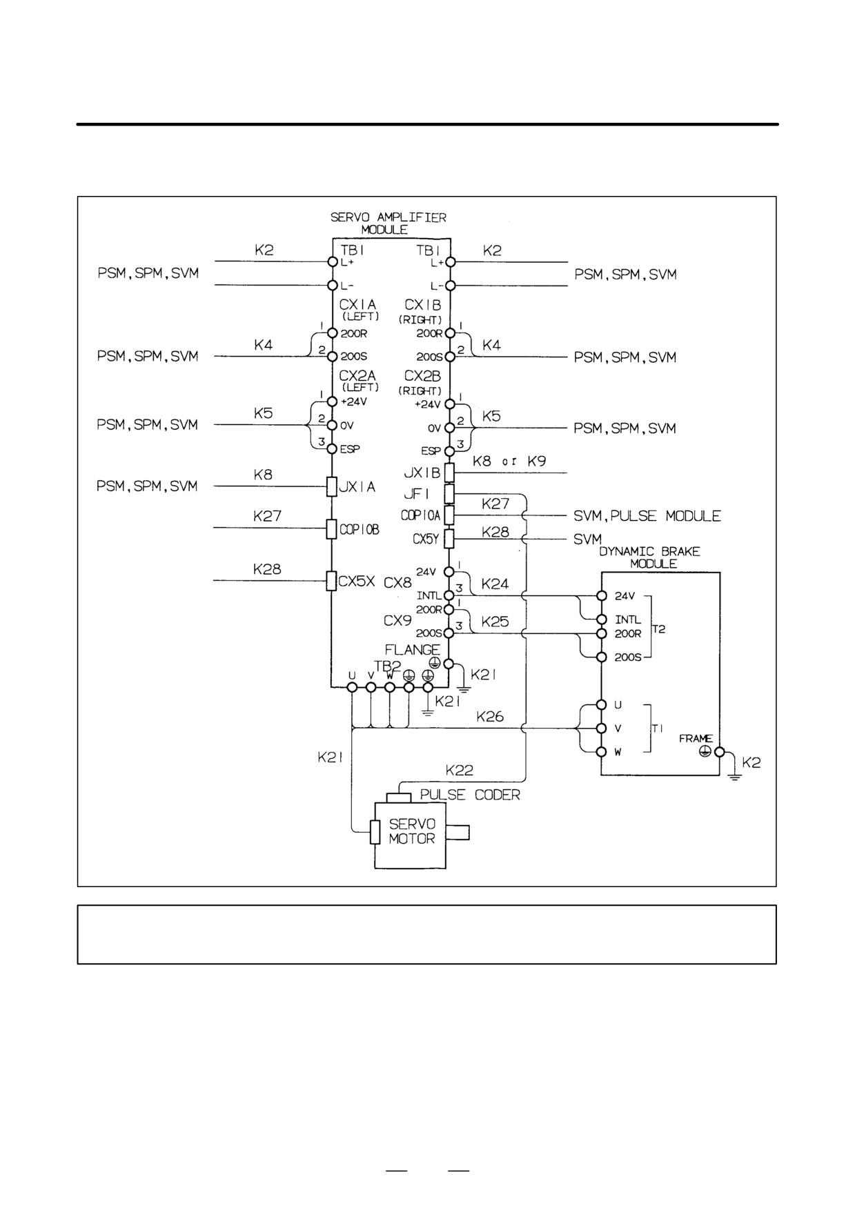
(C) FSSB interface (Example: SVM2)
SPM, SVM /
Terminating connector
Battery unit, SVM
CNC unit, SVM, and
pulse module
Cooling fan
For the
SVM1-130 only
Circuit
breaker 2
248
B-65162E/03
9.CONNECTION
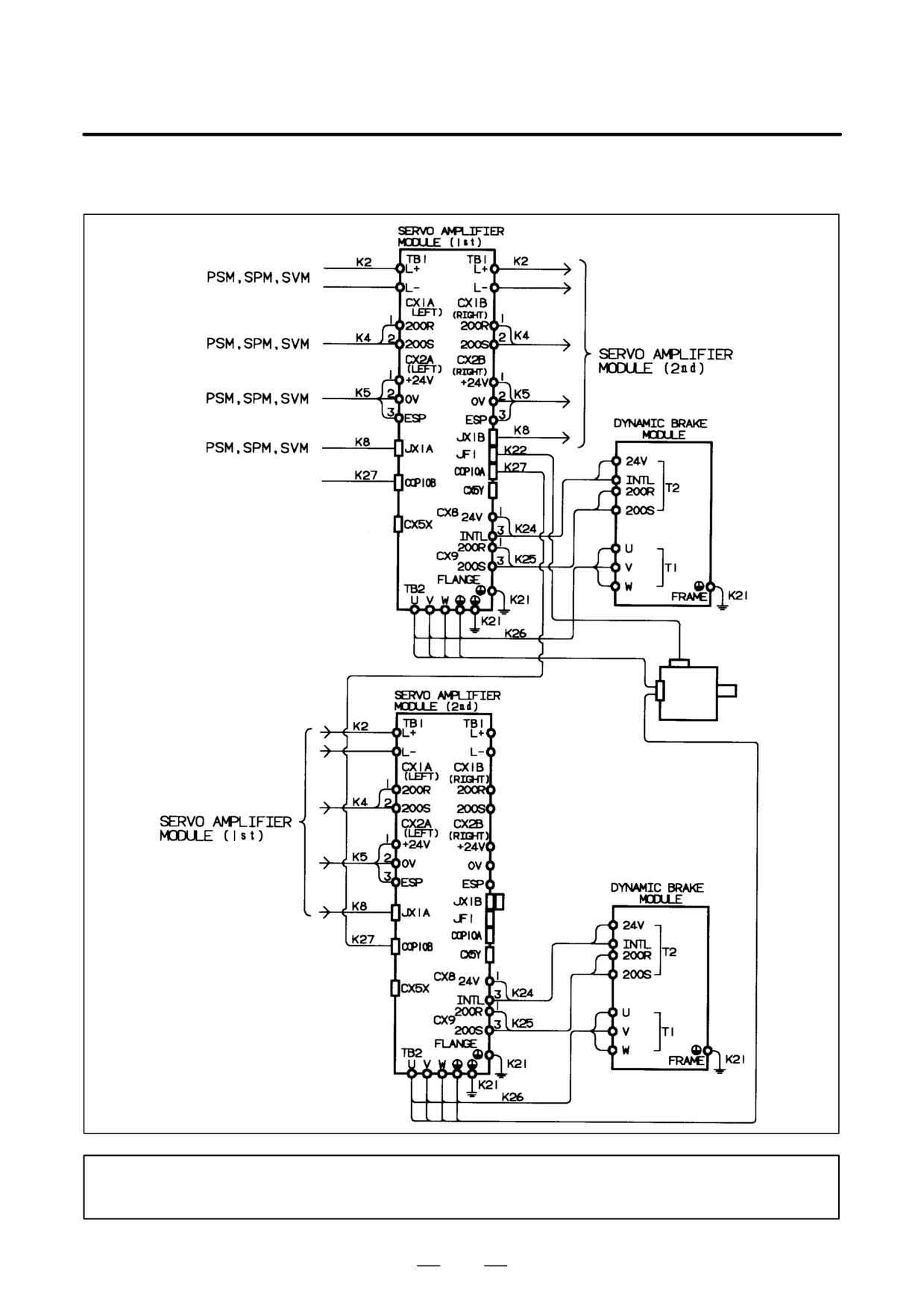
(D) FSSB interface (Example: SVM1-240 and SVM1-360)
SPM, SVM /
Terminating connector
CNC unit, SVM, and
pulse module
Battery unit, SVM
NOTE
Each of the SVM1-240 and SVM1-360 requires one dynamic brake module.
249
9. CONNECTION
B-65162E/03
(E) FSSB interface (Example: Two SVM1-240 units are used.)
CNC unit, SVM, and
pulse module
Pulse coder
Servo
motor
Terminating
connector
NOTE
Each SVM may require one PSM depending on the service condition of the motor.
250
B-65162E/03
9.CONNECTION
(1) Detailed description of the connection of cable K2
See 9.2.1 (2).
(2) Detailed description of the connection of cable K5
See 9.2.1 (5).
(3) Detailed description of the connection of cable K8
See 9.2.1 (8).
(4) Detailed description of the connection of cable K9
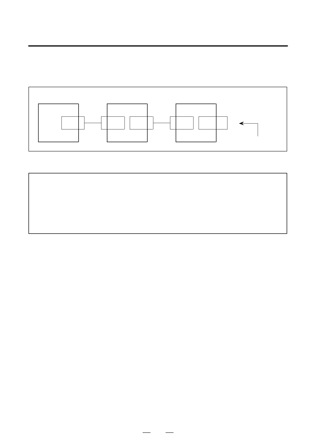
Cable K9 is a terminating connector. Its connection is shown below.
SVM
SPM
JX1B
(5) IALM
(6) 0V
Shorted
Pin arrangement of terminating connector K9
10
20
09
19
08
18
07
17
06
0V
16
05
IALM
15
04
14
03
13
02
12
01
11
251
9. CONNECTION
B-65162E/03
[Terminating connector K9]
Terminating connector K9 is shipped together with the PSM. K9 must
be inserted into the SVM/SPM at JX1B when the unit is installed.
SVM
SVM
SPM
SPM
PSM
K8
K8
JX1B
JX1A
JX1B
JX1A
JX1B
K9
Terminating connector
NOTE
1
Alarm signals are sent from the PSM to SVM/SPM units connected in series using cable K8.
Terminating connector K9 must be attached to the K8 cable connector of the SVM/SPM at the
farthest end. If no terminating connector is attached, the magnetic contactor (MCC) outside
these units cannot be turned on, so that the motors can not be driven.
2
Terminating connector K9 is shipped together with the PSM; it does not have to be ordered
separately. When cabling the units, insert the terminating connector into connector JX1B of
the SVM/SPM at the farthest end.
252
B-65162E/03
9.CONNECTION
(5) Detailed description of the connection of cable K11
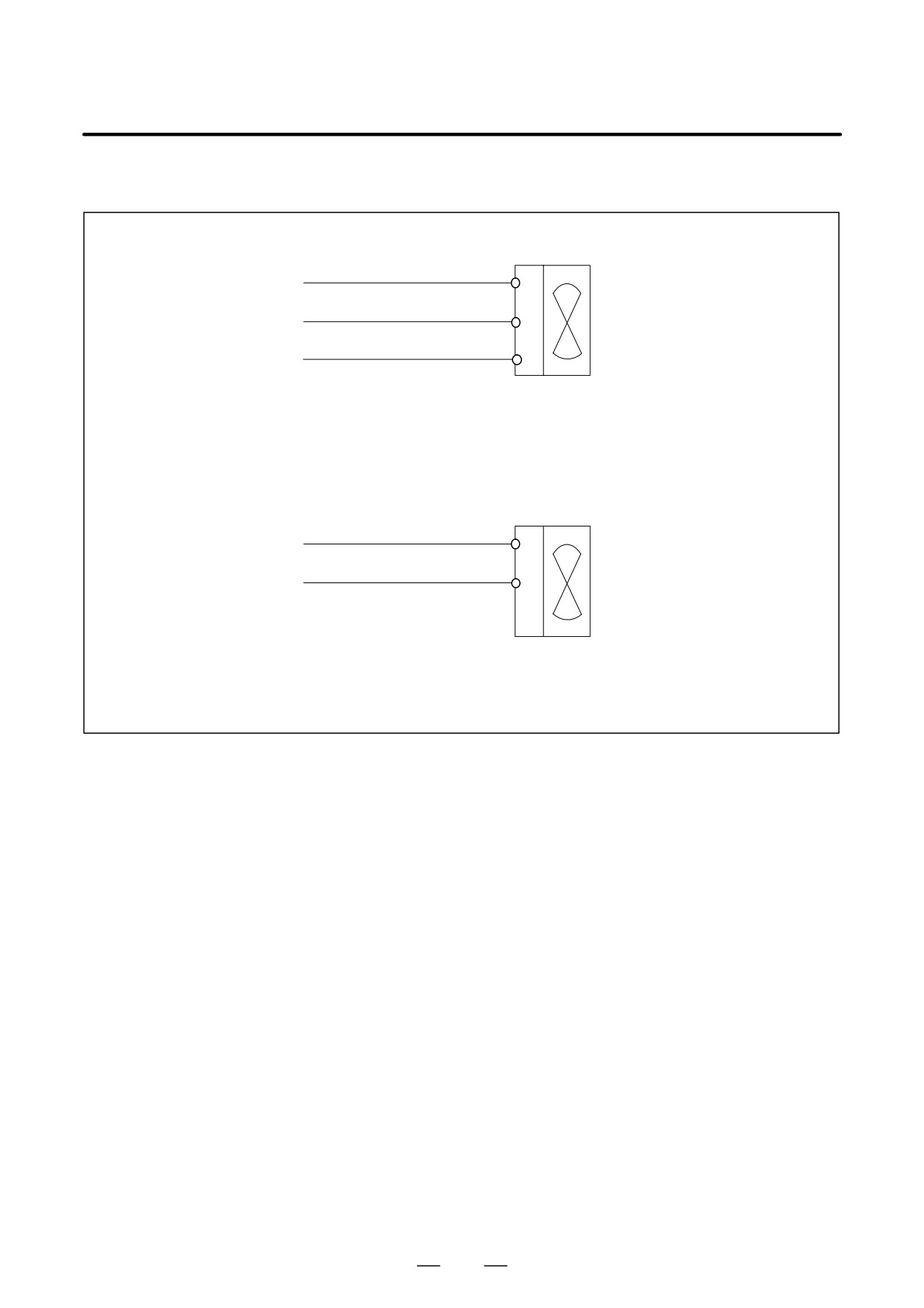
Power for fan motor
200V, three-phase
200R
R
R0
200S
S
S0
Fan motor
200T
T
T0
Cable specification: Use a three-conductor polyvinyl heavy-duty power cable (JIS C3312)
having a conductor size of 2 mm2 or larger.
Fan motor terminal screw: M4
Power for cooling fan (for the SVM-130 only)
200V, single-phase
200R
R
R0
200S
S
S0
Fan motor
Cable specification: Two-conductor polyvinyl heavy-duty power cable (JIS C3312),
conductor size of 1.25 mm2 (50/0.18), PVC sheath 9.6 mm in diameter
Applicable receptacle terminal: 6.3 mm (0.250 in.) series
(6) Detailed description of the connection of cable K11
Note that the type of the cable K21 connector on the motor side varies with
the motor model.
The conductors of cable K21 must be thick enough to carry the rated
current of the corresponding motor. To make the connection waterproof,
select a connector diameter that matches the cable clamp. To make it
comply with the CE marking standard, observe the related cautions.
(Refer to the FANUC AC SERVO MOTOR α Series Descriptions
B-65142E for details).
For an explanation of how to connect a model having a brake, refer also
to the FANUC AC SERVO MOTOR α Series Descriptions B-65142E.
253
9. CONNECTION
B-65162E/03
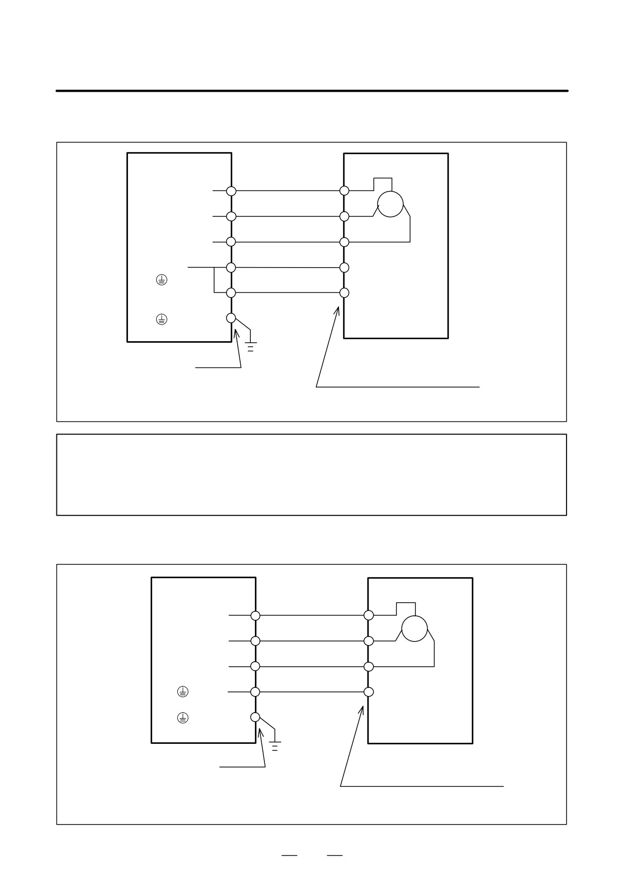
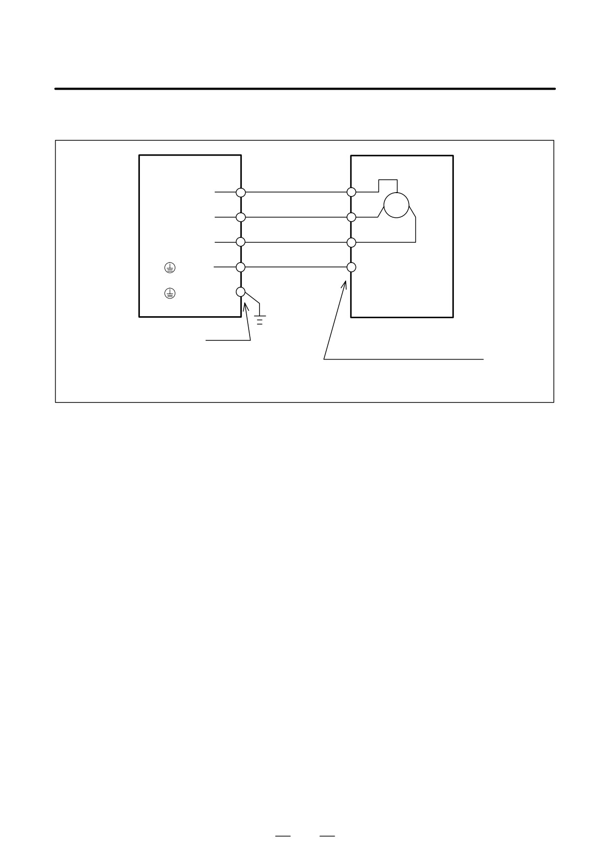
(a) Models α1/3000, α2/2000, α2/3000, αM2/3000, and αM2.5/3000
SVM
Motor
1
U
TB2(UL,UM,UN)
2
V
TB2(VL,VM,VN)
3
W
TB2(WL,WM,WN)
4
G (Motor body)
TB2 (
)
(Note)
G (Connector shell)
TB2 (
)
Screw M4
Connector used at the cable end:
Refer to FANUC AC SERVO MOTOR
α Series Descriptions B-65142E.
Example cable:
0.75 mm2
four-conductor heavy-duty power cable
NOTE
To satisfy the CE marking requirements, it is necessary to ground the connector shell at the
cable end. In this case, the specification of the connector will be different. Refer to
”Requirements for Compliance with the IEC34 Standards” and ”Connectors” in the FANUC AC
SERVO MOTOR α Series Descriptions B-65142E for details.
(b) Models α3/3000, α6/2000, α6/3000, αC3/2000, αC6/2000, αM6/3000, αM9/3000, αL6/3000, and αL9/3000
SVM
Motor
A
U
TB2(UL,UM,UN)
B
V
TB2(VL,VM,VN)
C
W
TB2(WL,WM,WN)
D
TB2 (
)
G (Motor body)
TB2 (
)
Connector used on the cable end:
Screw M4
Refer to FANUC AC SERVO MOTOR
α Series Descriptions B-65142E.
Example cable:
2.0 mm2
four-conductor heavy-duty power cable
254
B-65162E/03
9.CONNECTION
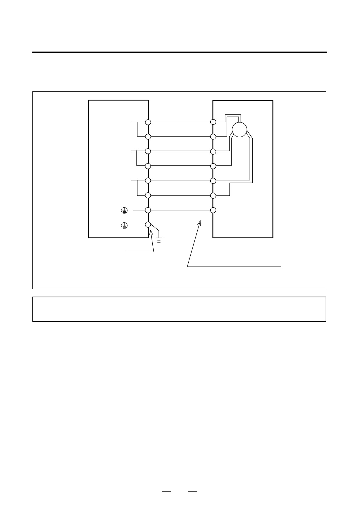
(c) Models α12/2000, α12/3000, α22/1500, α22/2000, α30/1200, αC12/2000, and αC22/1500
SVM
Motor
A
U
TB2(UL,UM,UN)
B
V
TB2(VL,VM,VN)
C
W
TB2(WL,WM,WN)
D
TB2 (
)
G (Motor body)
TB2 (
)
Screw M4
Connector used at the cable end:
Refer to FANUC AC SERVO MOTOR
α Series Descriptions B-65142E.
Example cable:
3.5 mm2
four-conductor heavy-duty power cable
255
9. CONNECTION
B-65162E/03
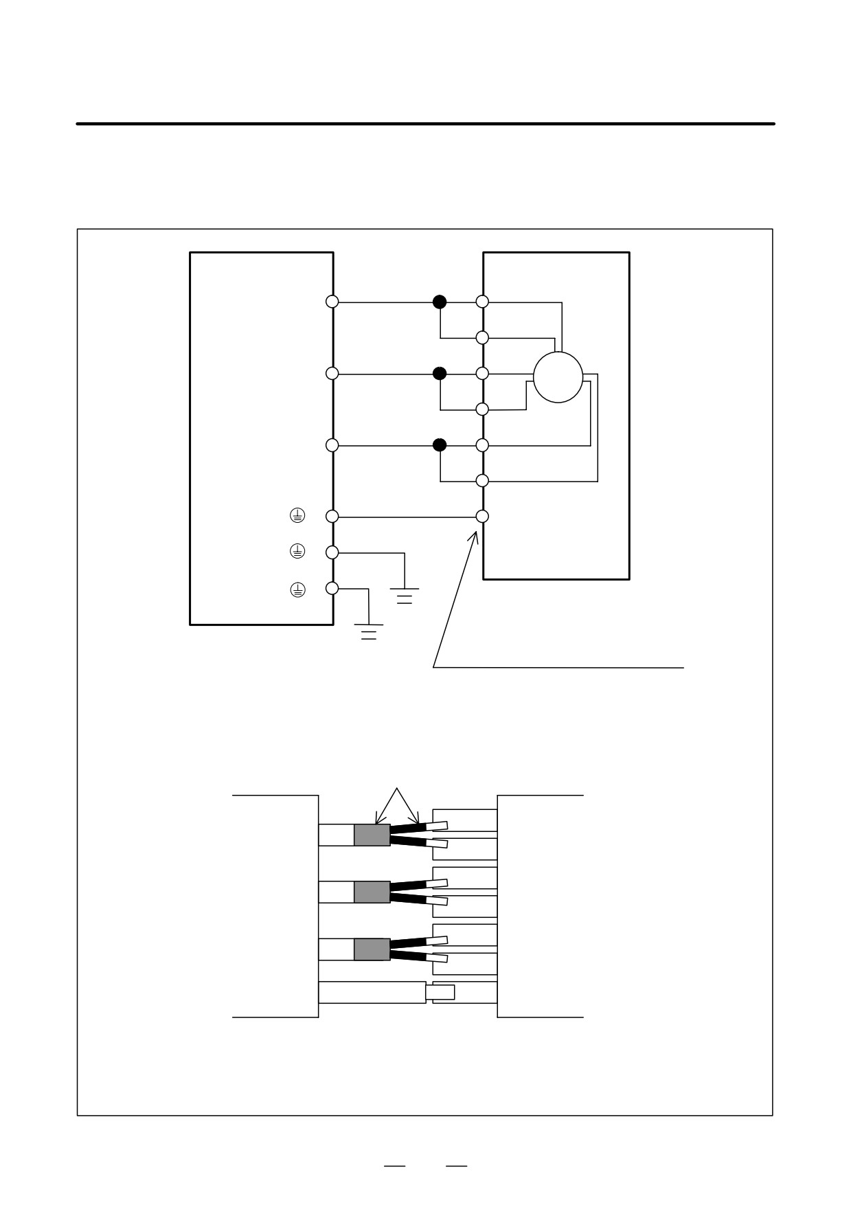
(d) Models α22/3000, α30/2000, α30/3000, α40/2000, α40/2000 with fan, αM22/3000, αM30/3000, αM40/3000
(with SVM1-130 used), αM40/3000 with fan (with SVM1-130 in use), αL25/3000, and αL50/2000
SVM
Motor
A
TB2(U)
B
U
C
TB2(V)
D
V
E
TB2(W)
F
W
TB2 (
)
G (Motor body)
TB2 (
)
Screw M4
Connector used at the cable end:
Refer to FANUC AC SERVO MOTOR
α Series Descriptions B-65142E.
Example cable:
3.5 mm2
2 (7 mm2) or 8 mm2
(PE (ground)) complex seven-conductor heavy-duty power cable
NOTE
Applicable crimp terminal:
8-4S
256
B-65162E/03
9.CONNECTION
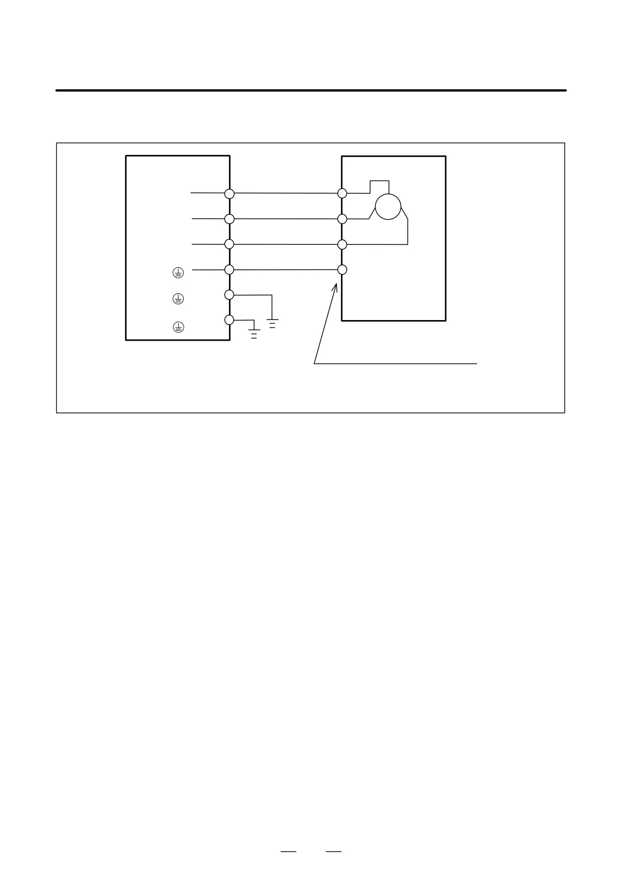
(e) Models αM40/3000 (with SMV1-240 and -360 used) and αM40/3000 with a fan (with the SVM1-240 and
-360 used)
Screw
Motor
SVM
M6
A
TB2(U)
U
B
M6
C
TB2(V)
V
D
M6
E
TB2(W)
W
F
M5
TB2 (
)
G (Motor body)
M5
TB2 (
)
M5
Flange (
)
Connector used at the cable end:
Refer to FANUC AC SERVO MOTOR
α Series Descriptions B-65142E.
Example of a cable:
10 mm2
4
Heat-shrinkable tube
Cable
A Connector
B
C
D
E
F
G
Divide the strands into two groups, and cover each strand group with heat-shrinkable
tube. Also cover the branching portion of the strands with heat-shrinkable tube
Cover all solder joints on the connector with nylon tube..
257
9. CONNECTION
B-65162E/03
(f) Models α65/2000, α100/2000, and α150/2000
Screw
SVM
Motor
U
M6
TB2 (U)
V
M6
TB2 (V)
W
M6
TB2 (W)
M6
TB2 (
)
G (Motor body)
M5
TB2 (
)
M5
Flange (
)
Terminal board:
Refer to FANUC AC SERVO MOTOR
α Series Descriptions B-65142E.
Example cable:
22 mm2
four-conductor heavy-duty power cable
258
B-65162E/03
9.CONNECTION
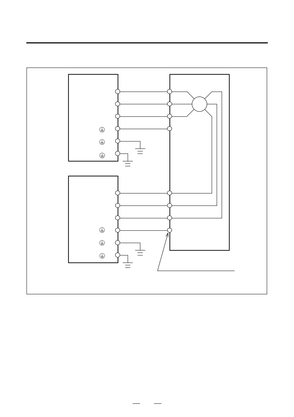
(g) Models α300/1200 and α400/1200
Screw
SVM
Motor
M6
U1
TB2(U)
M6
V1
TB2(V)
M6
W1
TB2(W)
M6
TB2 (
)
G (Motor body)
M5
TB2 (
)
M5
Flange (
)
Screw
SVM
M6
U2
TB2(U)
M6
V2
TB2(V)
M6
W2
TB2(W)
M6
TB2 (
)
G (Motor body)
M5
TB2 (
)
M5
Flange (
)
Terminal board:
Refer to FANUC AC SERVO MOTOR
α Series Descriptions B-65142E.
Example cable:
22 mm2
four-conductor heavy-duty power cable
259
9. CONNECTION
B-65162E/03
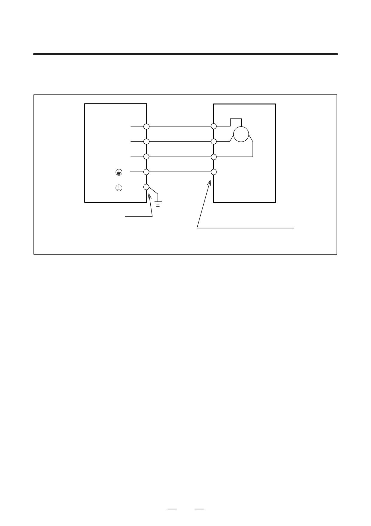
(h) Models α3/3000HV, α6/3000HV, α12/3000HV, α22/3000HV, α30/3000HV, αM6/3000HV, αM9/3000HV,
αM22/3000HV, and αM30/3000HV
SVM
Motor
U
TB2 (U)
V
TB2 (V)
W
TB2 (W)
TB2 (
)
G (Motor body)
TB2 (
)
Screw M4
Connector used at the cable end:
Refer to FANUC AC SERVO MOTOR
α Series Descriptions B-65142E.
Example cable:
3.5 mm2
four-conductor heavy-duty power cable
260
B-65162E/03
9.CONNECTION
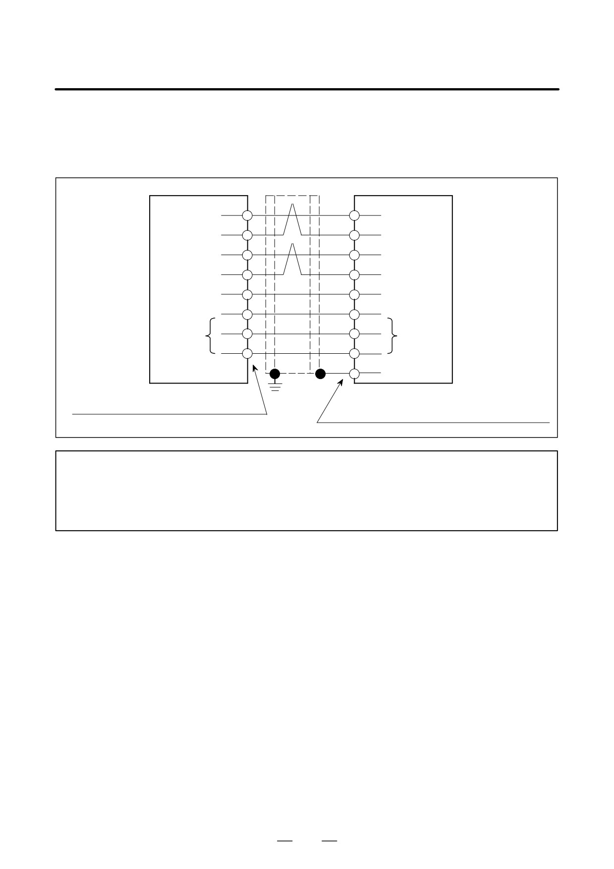
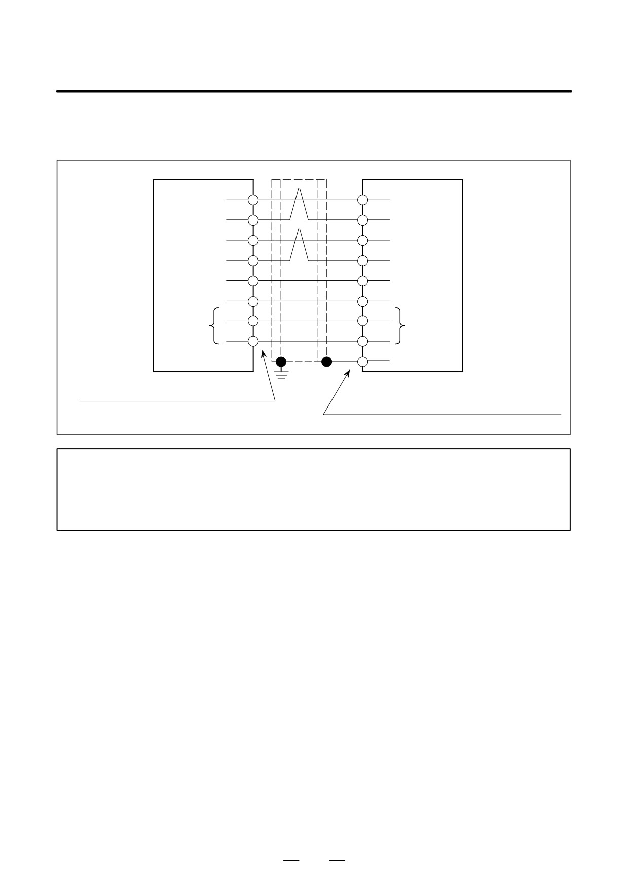
(7) Detailed description of the connection of cable K22
Connection with the FS0-C or FS15-A
(a) Models α1/3000, α2/2000, α2/3000, αM2/3000, and αM2.5/3000
CNC
Motor
(16)
SD
(12)
(17)
*SD
(13)
(14)
REQ
(5)
(15)
*REQ
(6)
(4, 5, 6)
+5V
(8, 15)
(1, 2)
0V
(1, 2, 3)
(3)
0VA
(10)
(Note)
(Note)
(7)
+6VA
(14)
Shielding
(4)
Connector :
Connector used at the cable end:
MR-20LFH (Honda Tsushin Kogyo Co., Ltd.)
Refer to FANUC AC SERVO MOTOR α Series
Descriptions B-65142E.
NOTE
For the incremental pulse coder, it is not necessary to connect pins 3 and 7 of the connector
on the CNC side to pins 10 and 14 of the connector on the motor side. No problem will result
if they are connected, however. So, a cable for the absolute pulse coder can also be used for
the incremental pulse coder.
261
9. CONNECTION
B-65162E/03
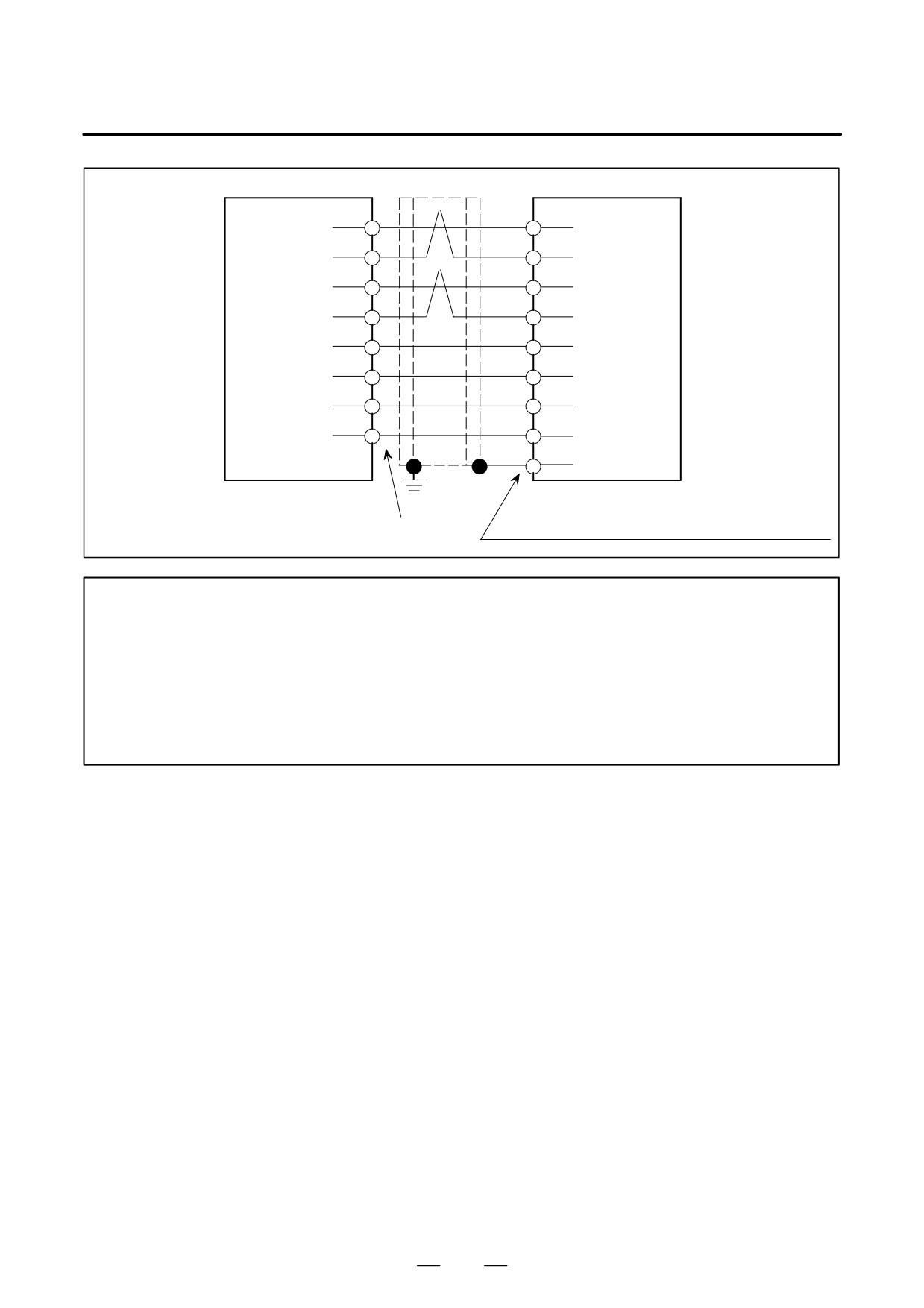
Relay unit
Motor
(16)
SD
(12)
(17)
*SD
(13)
(14)
REQ
(5)
(15)
*REQ
(6)
(4, 5)
+5V
(8, 15)
(1, 2)
0V
(1, 2, 3)
(3)
0VA
(10)
(6)
+6VA
(14)
Shielding
(4)
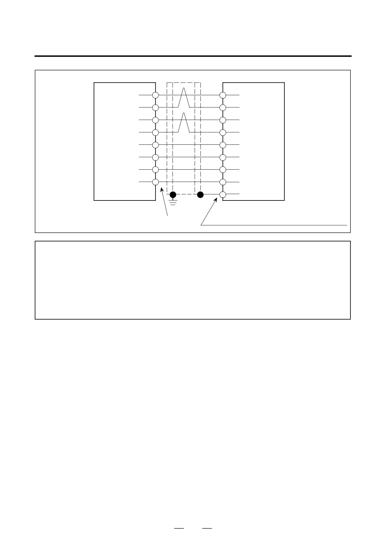
Connector :
Connector used at the cable end:
MR-20LFH (Honda Tsushin Kogyo Co., Ltd.)
Refer to FANUC AC SERVO MOTOR α Series
Descriptions B-65142E.
NOTE
Cables used in common for (a) and (b)
:
+5V, 0V...0.5 mm2 or larger
2
(for length of 14 m or less)
:
+6VA, 0VA...0.5 mm2 or larger
: SD, *SD, REQ, *REQ...twisted pair 0.18 mm2
or larger
If the cable is 14 m or longer, keep the electrical resistance across each of the 0V and +5V lines
to within 0.5Ω .
262
B-65162E/03
9.CONNECTION
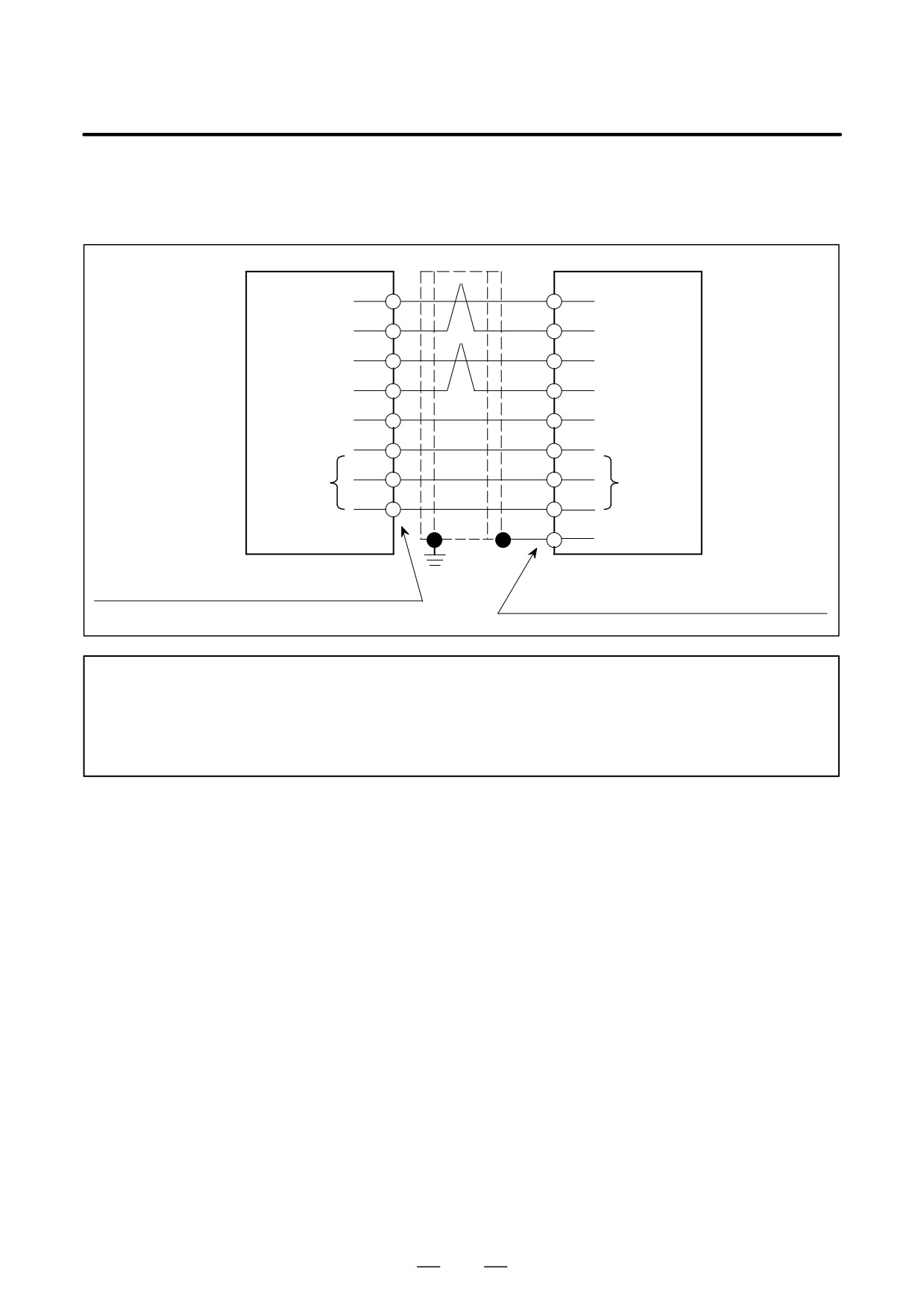
(b) Models α3/3000 to α40/2000, α65/2000 to α150/2000, αC3/3000 to αC22/1500, αM6/3000 to αM40/3000,
and αL6/3000 to αL50/2000
CNC
(16)
SD
(A)
Motor
(17)
*SD
(D)
(14)
REQ
(F)
(15)
*REQ
(G)
(4, 5, 6)
+5V
(J, K)
(1, 2)
0V
(N, T)
(3)
0VA
(S)
(Note)
(Note)
(7)
+6VA
(R)
Shielding
(H)
|
Connector :
Connector used at the cable end:
MR-20LFH (Honda Tsushin Kogyo Co., Ltd.)
Refer to FANUC AC SERVO MOTOR α Series
Descriptions B-65142E.
NOTE
For the incremental pulse coder, it is not necessary to connect pins 3 and 7 of the connector
on the CNC side to pins R and S of the connector on the motor side. No problem will result if
they are connected, however. So, a cable for the absolute pulse coder can also be used for
the incremental pulse coder.
263
9. CONNECTION
B-65162E/03
Relay unit
Motor
(16)
SD
(A)
(17)
*SD
(D)
(14)
REQ
(F)
(15)
*REQ
(G)
(4, 5)
+5V
(J, K)
(1, 2)
0V
(N, T)
(3)
0VA
(S)
(6)
+6VA
(R)
Shielding
(H)
Connector :
Connector used at the cable end:
MR-20LFH (Honda Tsushin Kogyo Co., Ltd.)
Refer to FANUC AC SERVO MOTOR α Series
Descriptions B-65142E.
NOTE
Cables used in common for (a) and (b)
:
+5V, 0V...0.5 mm2 or larger
2
(for length of 14 m or less)
:
+6VA, 0VA...0.5 mm2 or larger
: SD, *SD, REQ, *REQ...twisted pair 0.18 mm2
or larger
If the cable is 14 m or longer, keep the electrical resistance across each of the 0V and +5V lines
to within 0.5Ω .
264
B-65162E/03
9.CONNECTION
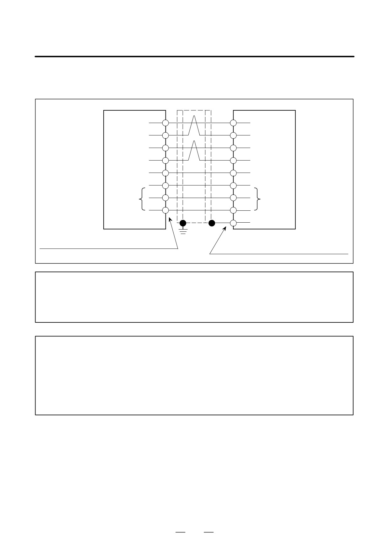
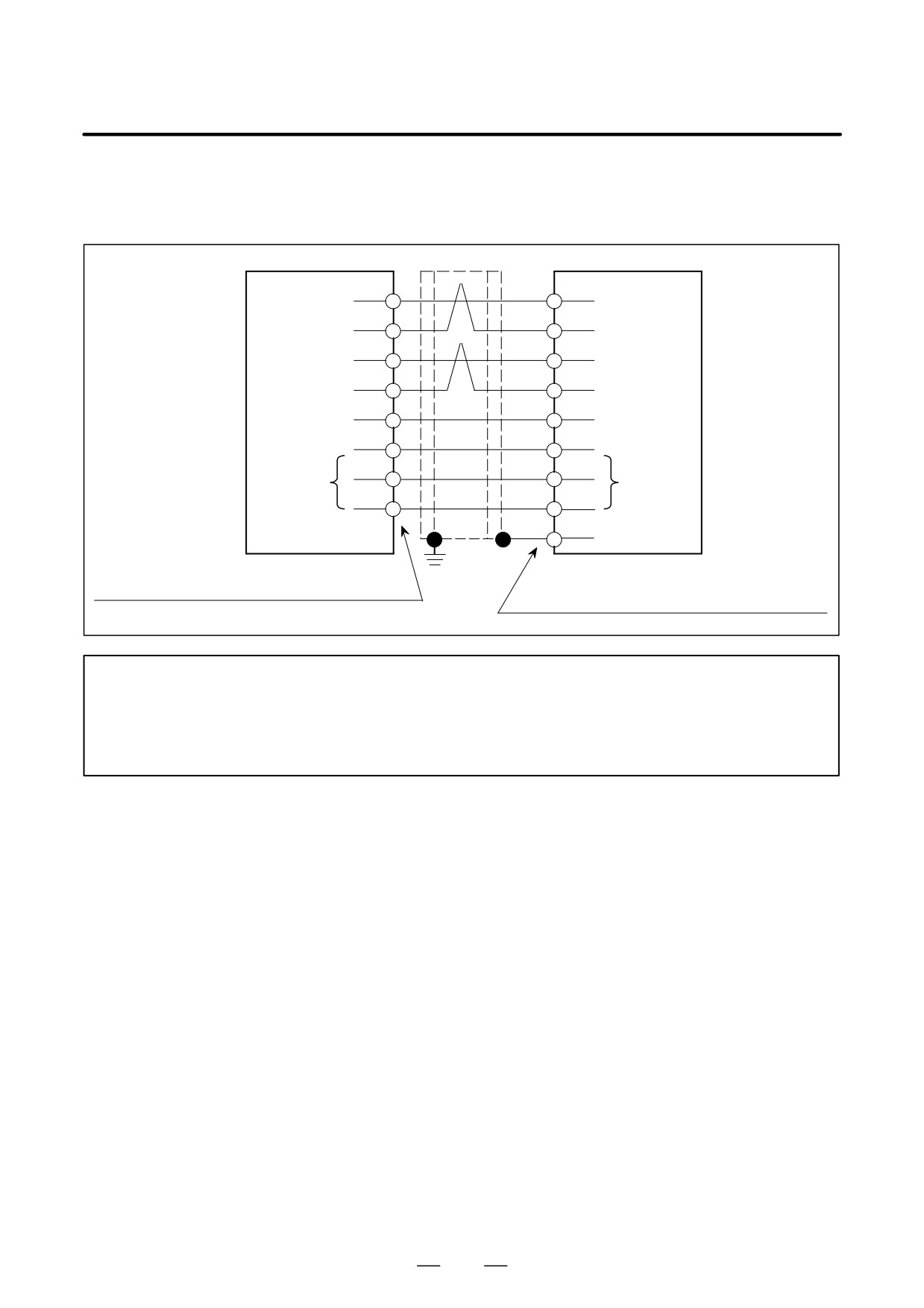
TYPE A interface
(a) Models α1/3000, α2/2000, α2/3000, αM2/3000, and αM2.5/3000
CNC
Motor
(1)
SD
(12)
(2)
*SD
(13)
(5)
REQ
(5)
(6)
*REQ
(6)
(9, 18, 20)
+5V
(8, 15)
(12, 14)
0V
(1, 2, 3)
(16)
0VA
(10)
(Note)
(Note)
(7)
+6VA
(14)
Shielding
(4)
Connector : FI40-2015S (Hirose Electric Co., Ltd.)
Connector used at the cable end:
Case
: FI-20-CV (Hirose Electric Co., Ltd.)
Refer to FANUC AC SERVO MOTOR α Series
Descriptions B-65142E.
NOTE
For the incremental pulse coder, it is not necessary to connect pins 7 and 16 of the connector
on the CNC side to pins 10 and 14 of the connector on the motor side. No problem will result
if they are connected, however. So, a cable for the absolute pulse coder can also be used for
the incremental pulse coder.
265
9. CONNECTION
B-65162E/03
(b) Models α3/3000 to α40/2000, α65/2000 to α150/2000, α300/1200 to α400/1200, αC3/3000 to αC22/1500,
αM6/3000 to αM40/3000, and αL6/3000 to αL50/2000
CNC
Motor
(1)
SD
(A)
(2)
*SD
(D)
(5)
REQ
(F)
(6)
*REQ
(G)
(9, 18, 20)
+5V
(J, K)
(12, 14)
0V
(N, T)
(16)
0VA
(S)
(Note)
(Note)
(7)
+6VA
(R)
Shielding
(H)
Connector : FI40-2015S (Hirose Electric Co., Ltd.)
Connector used at the cable end:
Case
: FI-20-CV (Hirose Electric Co., Ltd.)
Refer to FANUC AC SERVO MOTOR α Series
Descriptions B-65142E.
NOTE
For the incremental pulse coder, it is not necessary to connect pins 7 and 16 of the connector
on the CNC side to pins R and S of the connector on the motor side. No problem will result if
they are connected, however. So, a cable for the absolute pulse coder can also be used for
the incremental pulse coder.
NOTE
Cables used in common for (a) and (b)
:
+5V, 0V...0.5 mm2 or larger
2
(for length of 14 m or less)
:
+6VA, 0VA...0.5 mm2 or larger
: SD, *SD, REQ, *REQ...twisted pair 0.18 mm2
or larger
If the cable is 14 m or longer, keep the electrical resistance across each of the 0V and +5V lines
to within 0.5Ω .
266
B-65162E/03
9.CONNECTION
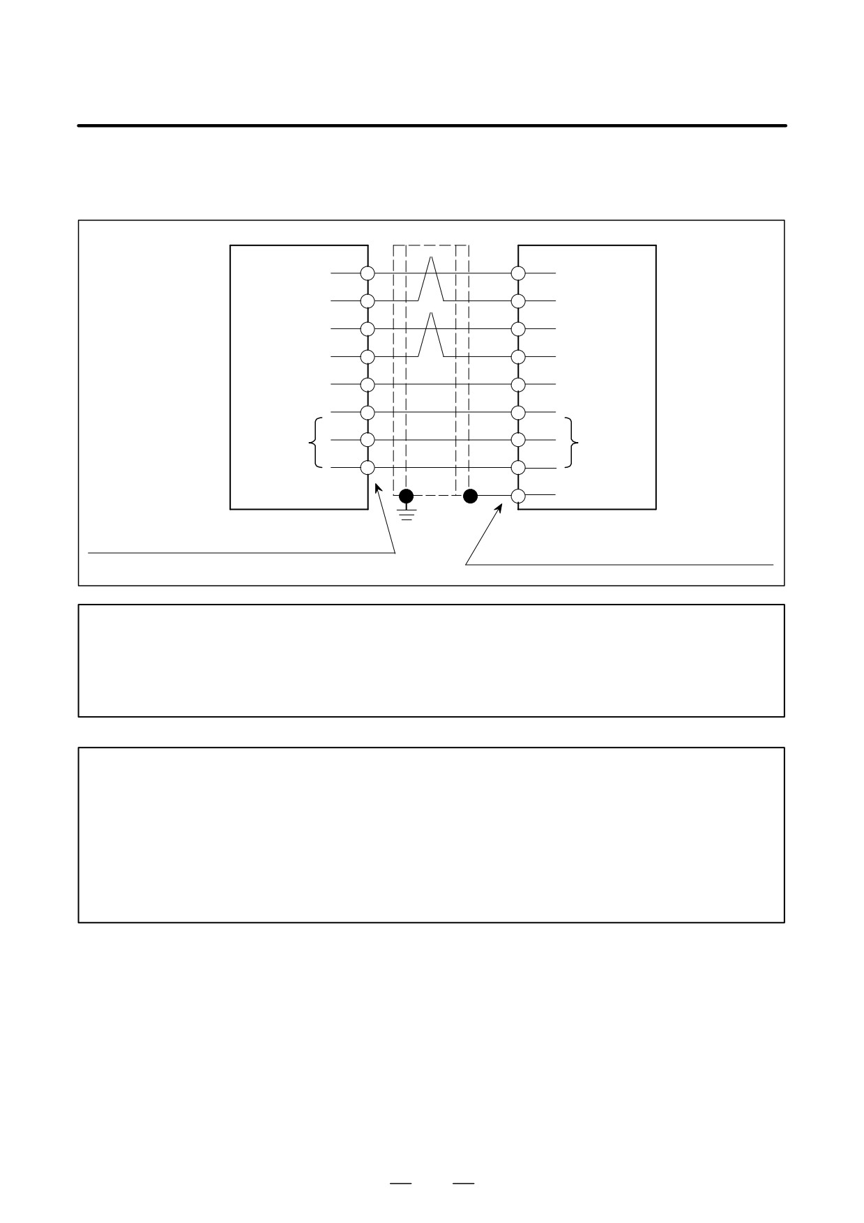
TYPE B and FSSB interfaces
(a) Models α1/3000, α2/2000, α2/3000, αM2/3000, and αM2.5/3000
SVM
Motor
(1)
SD
(12)
(2)
*SD
(13)
(5)
REQ
(5)
(6)
*REQ
(6)
(9, 18, 20)
+5V
(8, 15)
(12, 14)
0V
(1, 2, 3)
(16)
0VA
(10)
(Note)
(Note)
(7)
+6VA
(14)
Shielding
(4)
Connector : FI40-2015S (Hirose Electric Co., Ltd.)
Connector used at the cable end:
Case
: FI-20-CV (Hirose Electric Co., Ltd.)
Refer to FANUC AC SERVO MOTOR α Series
Descriptions B-65142E.
NOTE
For the incremental pulse coder, it is not necessary to connect pins 7 and 16 of the connector
on the CNC side to pins 10 and 14 of the connector on the motor side. No problem will result
if they are connected, however. So, a cable for the absolute pulse coder can also be used for
the incremental pulse coder.
267
9. CONNECTION
B-65162E/03
(b) Models α3/3000 to α40/2000, α65/2000 to α150/2000, α300/1200 to α400/1200, αC3/2000 to αC22/1500,
αM6/3000 to αM40/3000, and αL6/3000 to αL50/2000
SVM
Motor
(1)
SD
(A)
(2)
*SD
(D)
(5)
REQ
(F)
(6)
*REQ
(G)
(9, 18, 20)
+5V
(J, K)
(12, 14)
0V
(N, T)
(16)
0VA
(S)
(Note)
(Note)
(7)
+6VA
(R)
Shielding
(H)
Connector : FI40-2015S (Hirose Electric Co., Ltd.)
Connector used at the cable end:
Case
: FI-20-CV (Hirose Electric Co., Ltd.)
Refer to FANUC AC SERVO MOTOR α Series
Descriptions B-65142E.
NOTE
For the incremental pulse coder, it is not necessary to connect pins 7 and 16 of the connector
on the CNC side to pins R and S of the connector on the motor side. No problem will result if
they are connected, however. So, a cable for the absolute pulse coder can also be used for
the incremental pulse coder.
NOTE
Cables used in common for (a) and (b)
:
+5V, 0V...0.5 mm2 or larger
2
(for length of 14 m or less)
:
+6VA, 0VA...0.5 mm2 or larger
: SD, *SD, REQ, *REQ...twisted pair 0.18 mm2
or larger
If the cable is 14 m or longer, keep the electrical resistance across each of the 0V and +5V lines
to within 0.5Ω.
268
B-65162E/03
9.CONNECTION
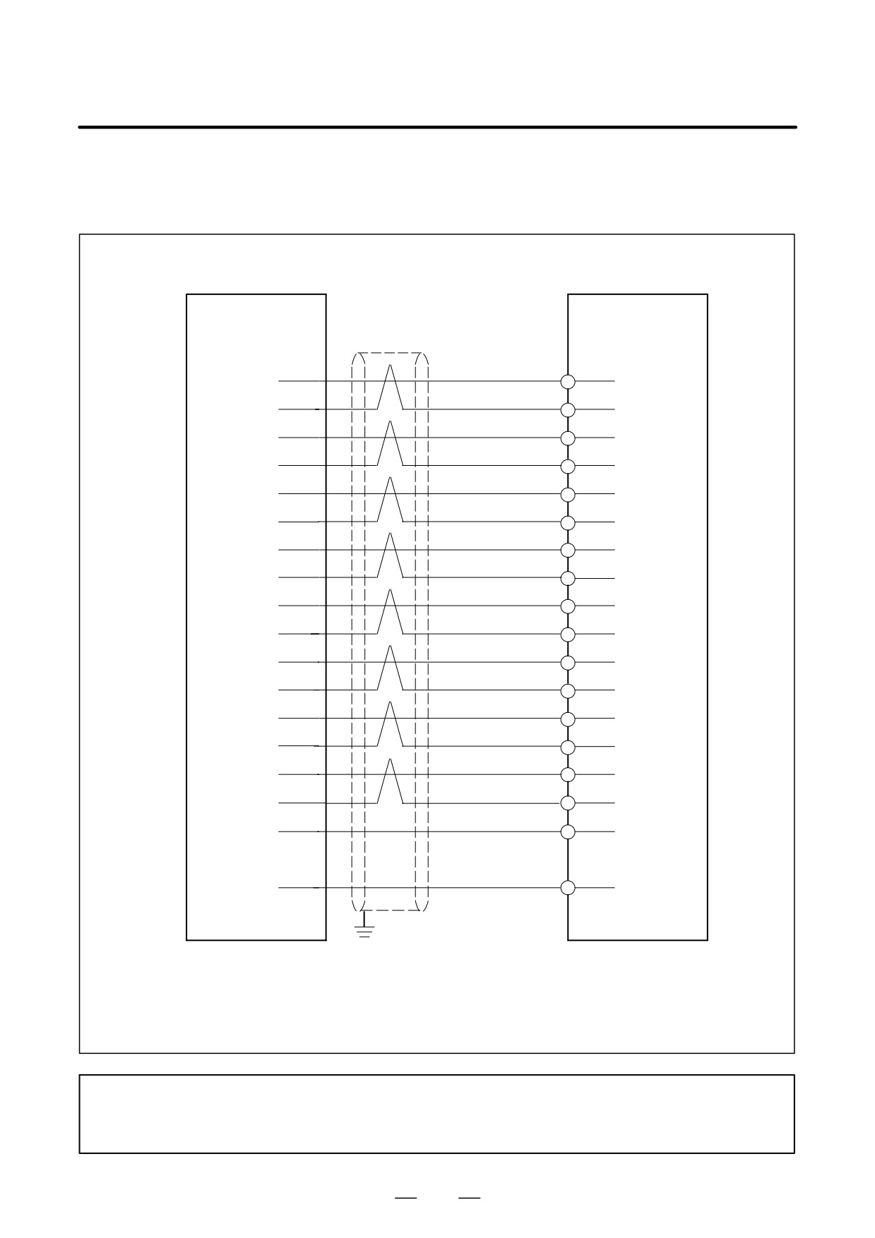
(8) Detailed description of the connection of cable K23
(a) TYPE A interface (for other than the FS-0C or FS-15A)
CNC
SVM
(3)
*PWMA (*ALM1)
(3)
(4)
COMA
(4)
(5)
*PWMB (*ALM2)
(5)
(6)
COMB
(6)
(7)
*PWMC (*ALM4)
(7)
(8)
COMC
(8)
(13)
*PWMD (*ALM8)
(13)
(14)
COMD
(14)
(15)
*PWME
(15)
(16)
COME
(16)
(17)
*PWMF
(17)
(18)
COMF
(18)
(1)
IR
(1)
(2)
GDR
(2)
(11)
IS
(11)
(12)
GDS
(12)
(10)
*MCON
(10)
(20)
*DRDY
(20)
(Connector : PCR-E20FA or others)
(Connector : PCR-E20FA or others)
Connector name
JV1B : L axis (first axis)
JV2B : M axis (second axis)
JV3B : N axis (third axis)
NOTE
Use inner conductors as pairs (1-2 and 11-12) for current feedback signals (IR and IS) to avoid
any external influence. Connector pins 9 and 19 are not used on either the CNC or SVM.
269
9. CONNECTION
B-65162E/03
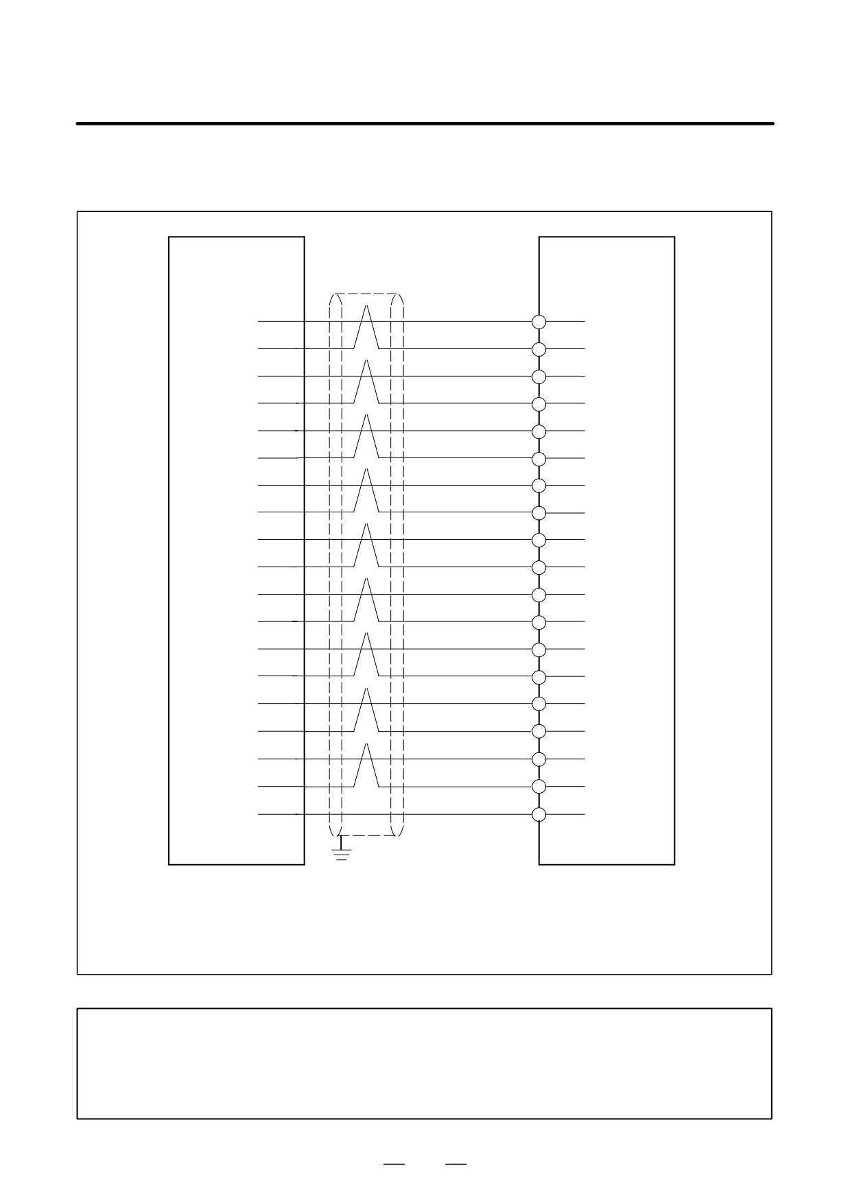
(b) TYPE A interface (for the FS-0C and FS-15A)
CNC
SVM
(1)
*PWMA (*ALM1)
(3)
(2)
COMA
(4)
(3)
*PWMB (*ALM2)
(5)
(4)
COMB
(6)
(5)
*PWMC (*ALM4)
(7)
(6)
COMC
(8)
(14)
*PWMD (*ALM8)
(13)
(15)
COMD
(14)
(16)
*PWME
(15)
(17)
COME
(16)
(18)
*PWMF
(17)
(19)
COMF
(18)
(8)
IR
(1)
(9)
GDR
(2)
(10)
IS
(11)
(11)
GDS
(12)
(12)
*MCON
(10)
(13)
GND
(9)
(7)
*DRDY
(20)
(Connector : MR-20RD or others)
(Connector : PCR-E20FA or others)
Connector name
JV1B : L axis (first axis)
JV2B : M axis (second axis)
JV3B : N axis (third axis)
NOTE
The wire (GND) connected to pin 13 of the connector on the CNC is paired with the *MCON
signal wire. This wire is not grounded on the SVM side.
Use inner conductors as pairs (1-2 and 11-12) for current feedback signals (IR and IS) to avoid
any external influence.
270
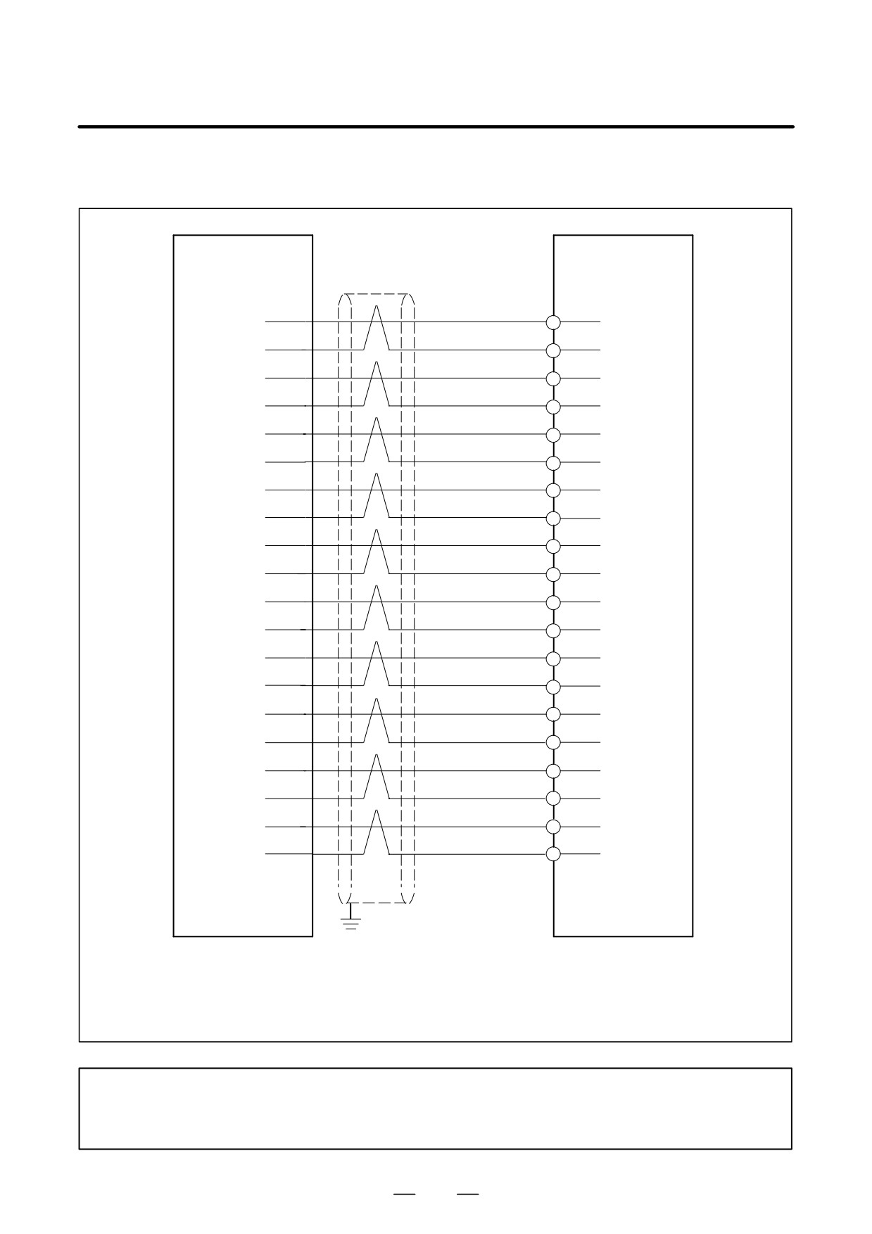
B-65162E/03
9.CONNECTION
(c) TYPE B interface
CNC
SVM
(3)
*PWMA (*ALM1)
(3)
(4)
0V
(4)
(5)
*PWMC (*ALM2)
(5)
(6)
0V
(6)
(7)
*PWME (*ALM4)
(7)
(8)
0V
(8)
(13)
*ENBL (*ALM8)
(13)
(14)
0V
(14)
(1)
IR
(1)
(2)
GDR
(2)
(11)
IS
(11)
(12)
GDS
(12)
(19)
0V
(19)
(20)
0V
(20)
(9)
*DRDY
(9)
(10)
*MCON
(10)
(15)
PD
(15)
(16)
*PD
(16)
(17)
PREQ
(17)
(18)
*PREQ
(18)
(Connector : PCR-E20FA or others)
(Connector : PCR-E20FA or others)
Connector name
JS1B : L axis (first axis)
JS2B : M axis (second axis)
JS3B : N axis (third axis)
NOTE
Use inner conductors as pairs (1-2 and 11-12) for current feedback signals (IR and IS) to avoid
any external influence.
271
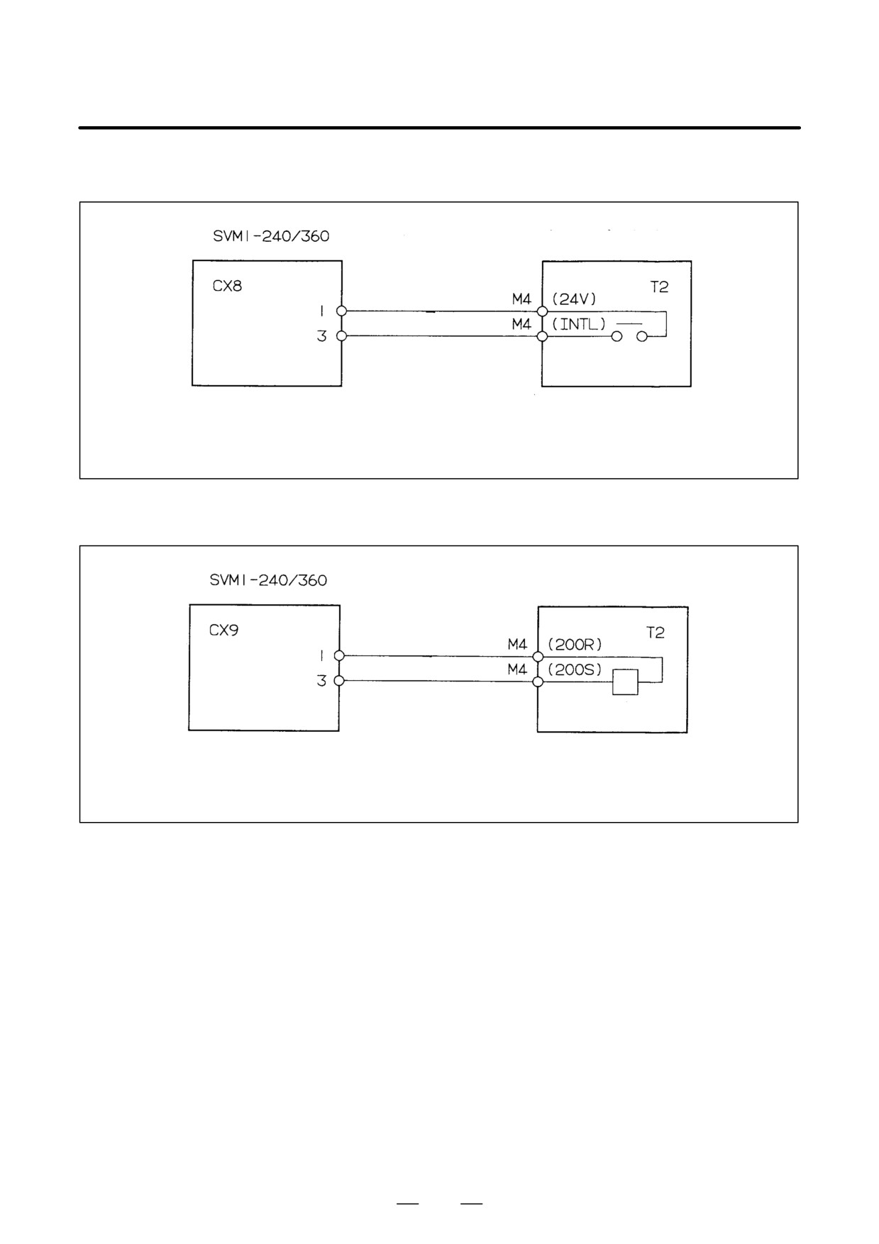
9. CONNECTION
B-65162E/03
(9) Detailed description of the connection of cable K24
Dynamic brake module
a-contact
Cable: Two-conductor polyvinyl heavy-duty power cable (JIS C3312),
1.25 mm2 (50/0.18), PVC sheath 9.6 mm in diameter
Connector: AMP connector with receptacle housing 1-178128-3 and
receptacle contact 1-178128-2
Crimp terminal:
2-4
(10) Detailed description of the connection of cable K25
Dynamic brake module
Coil
Cable: Two-conductor polyvinyl heavy-duty power cable (JIS C3312),
1.25 mm2 (50/0.18), PVC sheath 9.6 mm in diameter
Connector: AMP connector with receptacle housing 1-178128-3 and
receptacle contact 1-178128-2
Crimp terminal:
2-4
272