FANUC SERVO AMPLIFIER a series. DESCRIPTIONS (B-65162E/03) - page 7
8. EXTERNAL DIMENSIONS AND
B-65162E/03
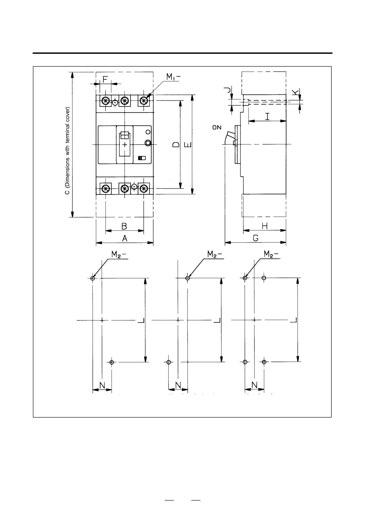
MAINTENANCE AREA
Two mounting holes (1)
Two mounting holes (2)
Four mounting holes
The circuit breakers have two or four mounting holes.
183
8. EXTERNAL DIMENSIONS AND
MAINTENANCE AREA
B-65162E/03
8.1.10
Magnetic Contactors
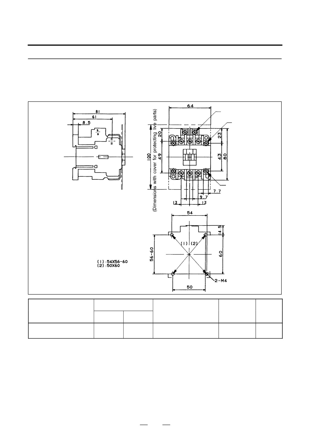
(a) A06B-6077-K121
(Dimensions with
Coil terminal M3.5
cover for protect-
ing live parts)
Main terminal M4
Auxiliary terminal M3.5
Dimensions for drilling mounting holes
Mounting (1) and (2) are possible.
Fuji Electric part number
Auxiliary con-
Orderingdrawing number
Operation coil voltage
Weight
tact structure
Body
Cover
200V/50Hz
A06B-6077-K121
SC-5-1
SZ-JC4
1a1b
0.38Kg
200-220V/60Hz
184
8. EXTERNAL DIMENSIONS AND
B-65162E/03
MAINTENANCE AREA
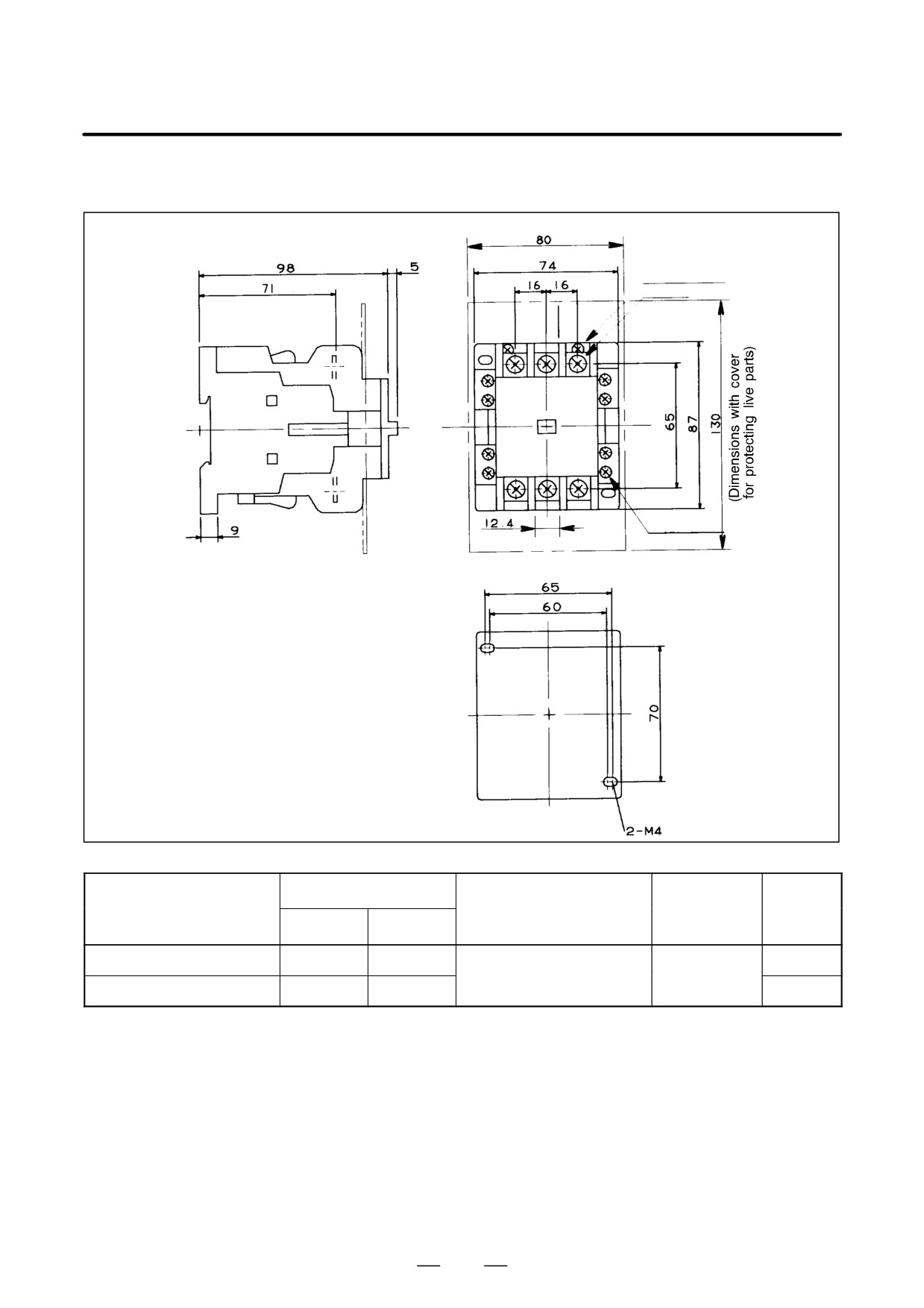
(b) A06B-6077-K122, A06B-6077-K123
(Dimensions with cover for protecting live parts)
Coil terminal M3.5
Main terminal M5
Auxiliary terminal M3.5
Dimensions for drilling mounting holes
Fuji Electric part number
Auxiliary con-
Orderingdrawing number
Operation coil voltage
Weight
tact structure
Body
Cover
A06B-6077-K122
SC-1N
SZ-1N/T
0.68Kg
200V/50Hz
2a2b
200-220V/60Hz
A06B-6077-K123
SC-2N
SZ-1N/T
0.68Kg
185
8. EXTERNAL DIMENSIONS AND
MAINTENANCE AREA
B-65162E/03
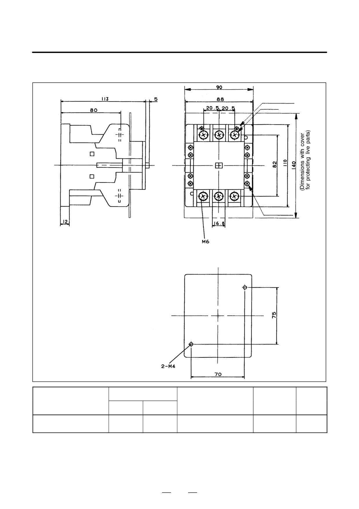
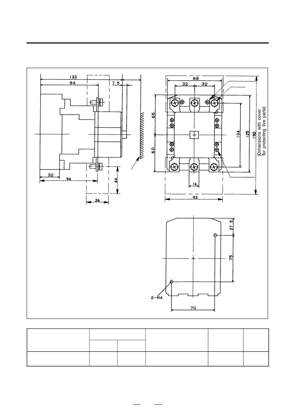
(c) A06B-6077-K124
(Dimensions with cover for protecting live parts)
Coil terminal M3.5
Main terminal M6
Auxiliary terminal M3.5
Dimensions for drilling mounting holes
Fuji Electric part number
Auxiliary con-
Orderingdrawing number
Operation coil voltage
Weight
tact structure
Body
Cover
200V/50Hz
A06B-6077-K124
SC-2SN
SZ-2SN/T
2a2b
1.3Kg
200-220V/60Hz
186
8. EXTERNAL DIMENSIONS AND
B-65162E/03
MAINTENANCE AREA
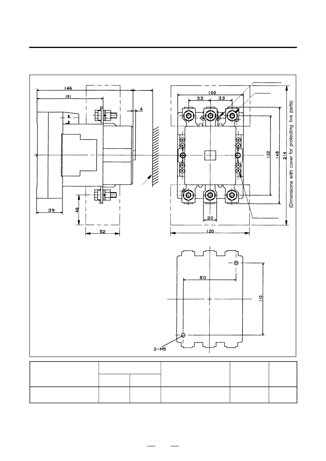
(d) A06B-6077-K125
30 min
Coil terminal M3.5
Main terminal M6
Grounding
metal
Auxiliary terminal M3.5
(Dimensions with cover for protecting live parts)
Dimensions for drilling mounting holes
Fuji Electric part number
Auxiliary con-
Orderingdrawing number
Operation coil voltage
Weight
tact structure
Body
Cover
200V/50Hz
A06B-6077-K124
SC-2SN
SZ-2SN/T
2a2b
1.5Kg
200-220V/60Hz
187
8. EXTERNAL DIMENSIONS AND
MAINTENANCE AREA
B-65162E/03
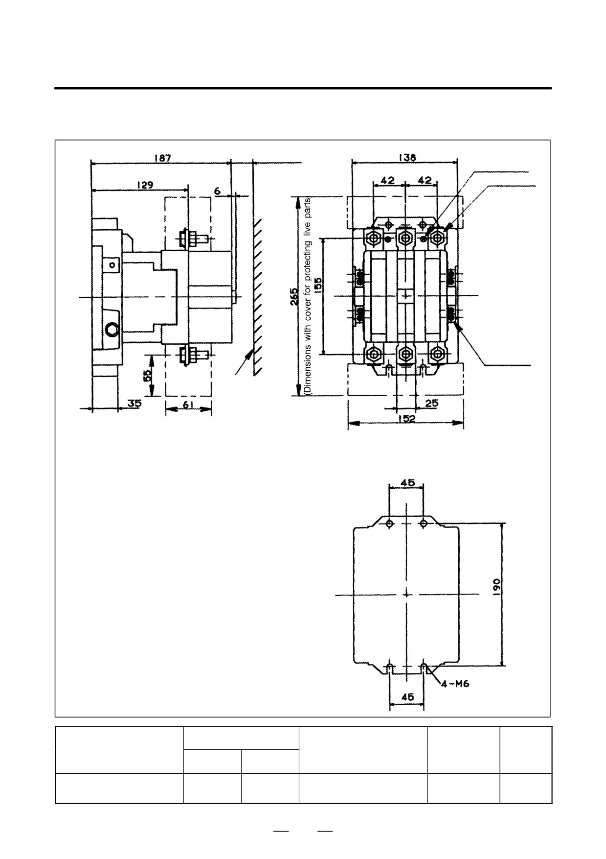
(e) A06B-6077-K126
Coil terminal M3.5
30 min
Main terminal M8
Grounding
metal
Auxiliary terminal M3.5
(Dimensions with cover for protecting live parts)
Fuji Electric part number
Auxiliary con-
Orderingdrawing number
Operation coil voltage
Weight
tact structure
Body
Cover
200V/50Hz
A06B-6077-K126
SC-5N
SZ-5N/T
2a2b
2.5Kg
200-220V/60Hz
188
8. EXTERNAL DIMENSIONS AND
B-65162E/03
MAINTENANCE AREA
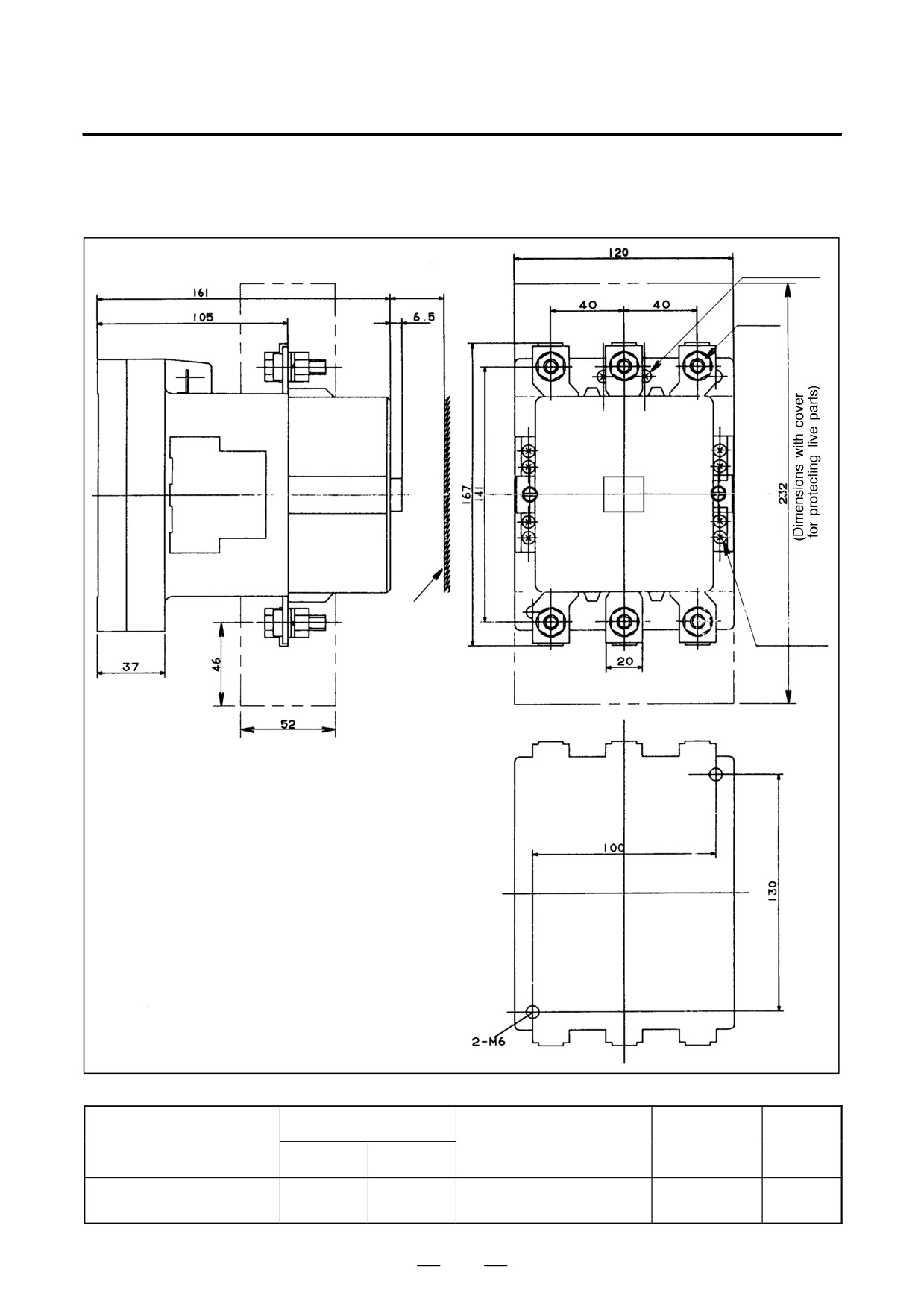
(f) A06B-6077-K127
30 min
Coil terminal M4
Main terminal M10
Auxiliary
terminal M4
Grounding
metal
(Dimensions with cover for protecting live parts)
Fuji Electric part number
Auxiliary con-
Orderingdrawing number
Operation coil voltage
Weight
tact structure
Body
Cover
200V/50Hz
A06B-6077-K127
SC-8N
SZ-8N/T
2a2b
5.2Kg
200-220V/60Hz
189
8. EXTERNAL DIMENSIONS AND
MAINTENANCE AREA
B-65162E/03
(g) A06B-6077-K128
Coil terminal
(Dimensions with cover for protecting live parts) M3.5
30 min
Main terminal
M8
Auxiliary
Grounding
terminal
metal
M3.5
Fuji Electric part number
Auxiliary con-
Orderingdrawing number
Operation coil voltage
Weight
tact structure
Body
Cover
200V/50Hz
A06B-6077-K128
SC-7N
SZ-5N/T
2a2b
3.4Kg
200-220V/60Hz
190
8. EXTERNAL DIMENSIONS AND
B-65162E/03
MAINTENANCE AREA
8.1.11
Lightning Surge
Protector
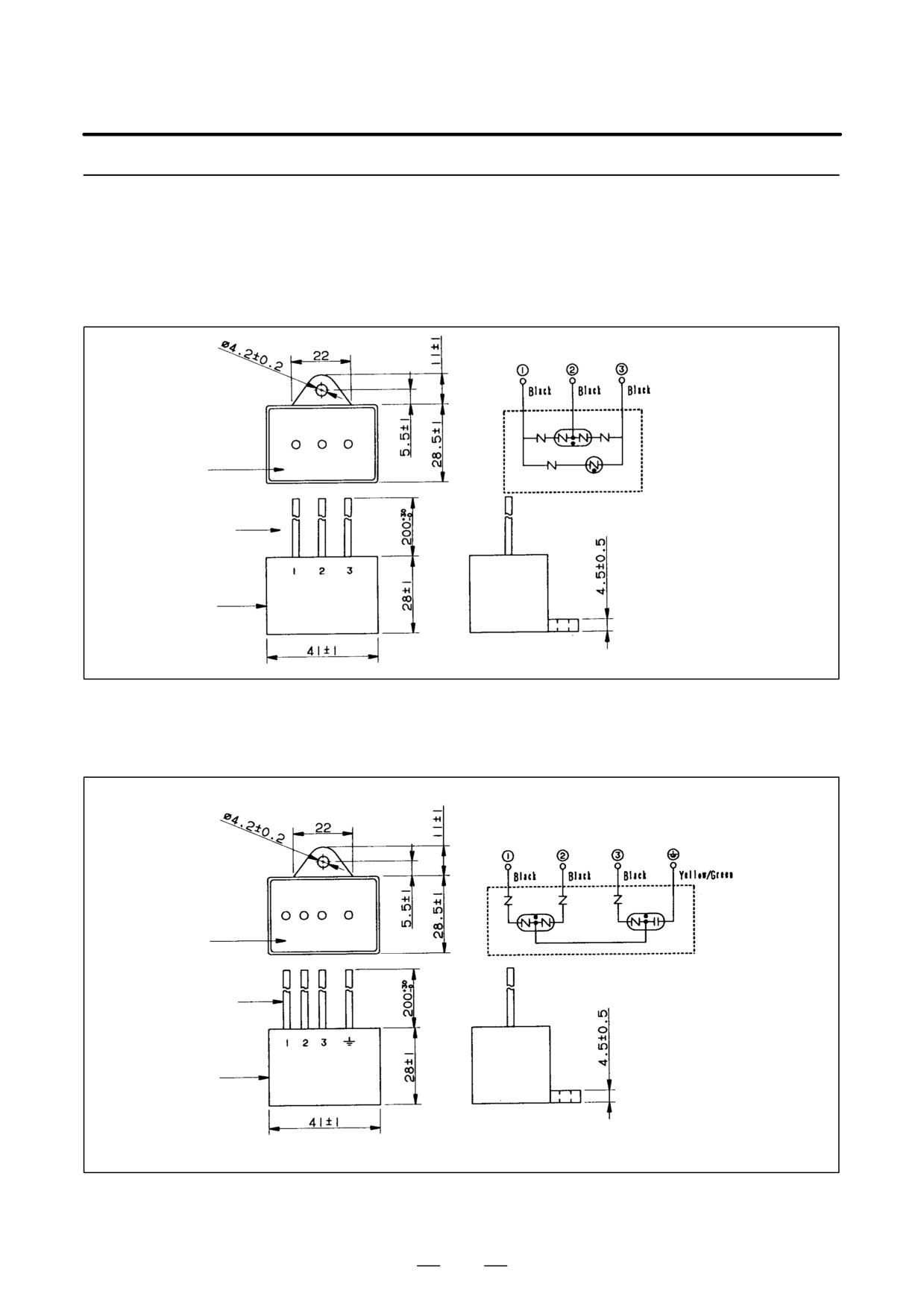
(a) A06B-6077-K142
Connection
diagram
Resin
Lead
Case
(1) For line-to-line installation: RAV-781BYZ-2
Connection
diagram
Resin
Lead
Case
(2) For line-to-ground installation: RAV-781BXZ-4
191
8. EXTERNAL DIMENSIONS AND
MAINTENANCE AREA
B-65162E/03
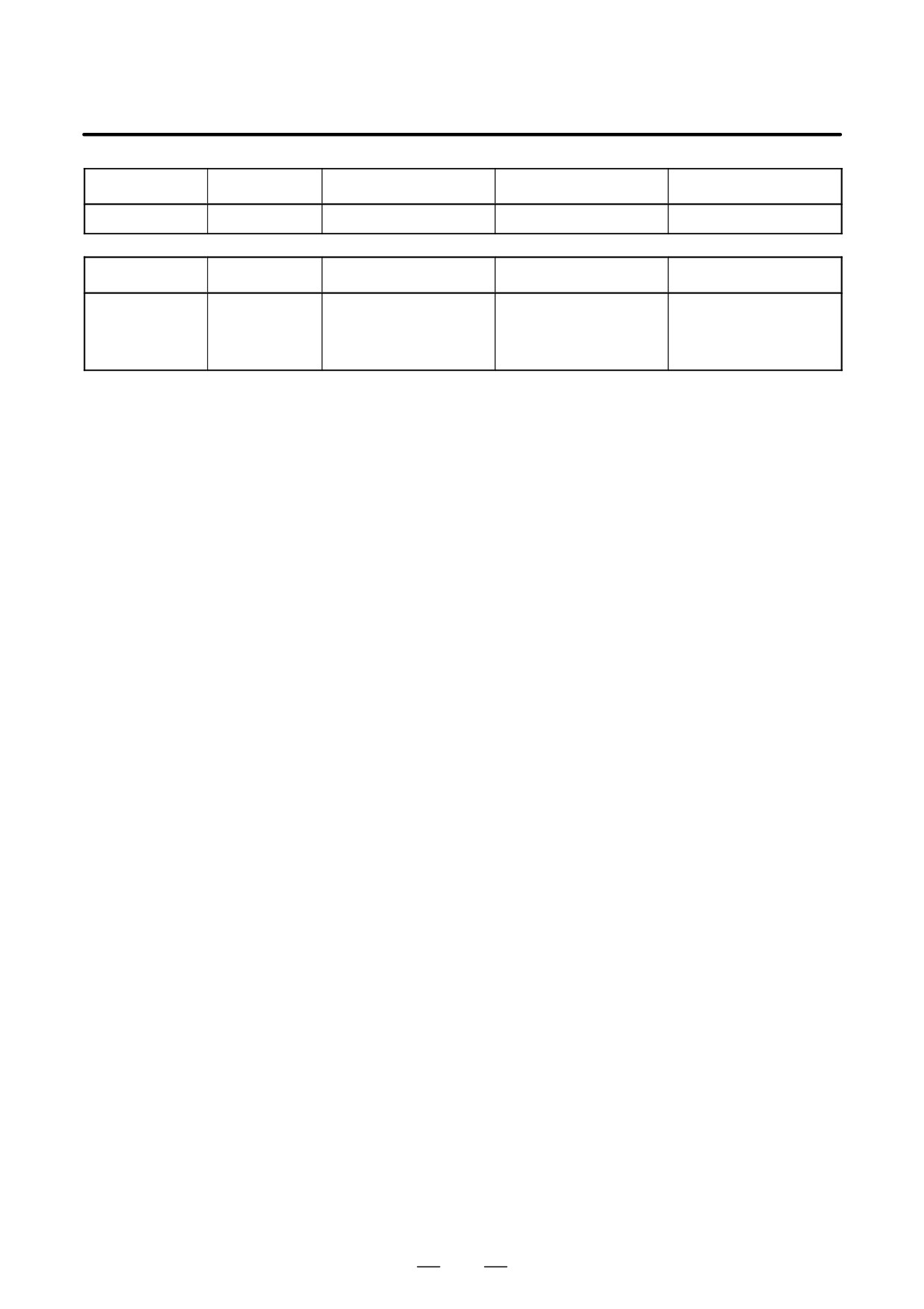
Specification
Rated voltage
Clamp voltage
Surge withstand current
Surge withstand voltage
R⋅A⋅V-781BYZ-2
AC250V
DC783V"10% (V1.0)
2500A (8/20µS)
20kV (1.2/50µS)
Specification
Rated voltage
Clamp voltage
Surge withstand current
Surge withstand voltage
line-to-line:
430VAC,
R⋅A⋅V-781BXZ-4
AC700V"20% (Ua)
2500A (8/20µS)
2.0kV (1.2/50µS)
line-to-ground:
250VAC
192
8. EXTERNAL DIMENSIONS AND
B-65162E/03
MAINTENANCE AREA
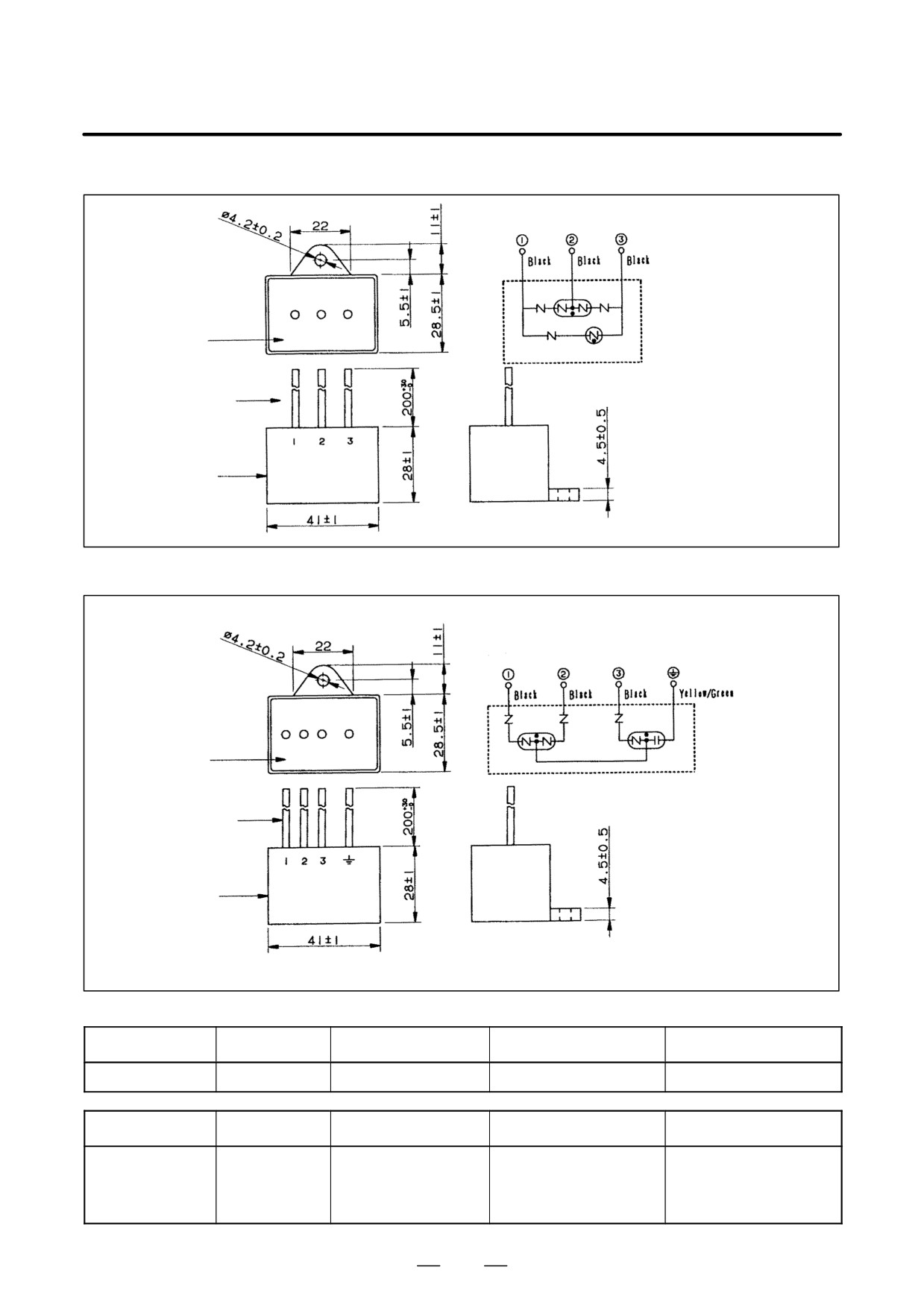
(b) A06B-6077-K143
Connection
diagram
Resin
Lead
Case
(1) For line-to-line installation: RAV-152BYZ-2A
Connection
diagram
Resin
Lead
Case
(2) For line-to-ground installation: RAV-801BXZ-4
Specification
Rated voltage
Clamp voltage
Surge withstand current
Surge withstand voltage
R⋅A⋅V-152BYZ-2A
AC460V
1470V"10% (V1.0)
2500A (8/20µS)
20kV (1.2/50µS)
Specification
Rated voltage
Clamp voltage
Surge withstand current
Surge withstand voltage
line-to-line:
500VAC,
R⋅A⋅V-801BXZ-4
AC800V"20% (Ua)
2500A (8/20µS)
2.32kV (1.2/50µS)
line-to-ground:
290VAC
193
8. EXTERNAL DIMENSIONS AND
MAINTENANCE AREA
B-65162E/03
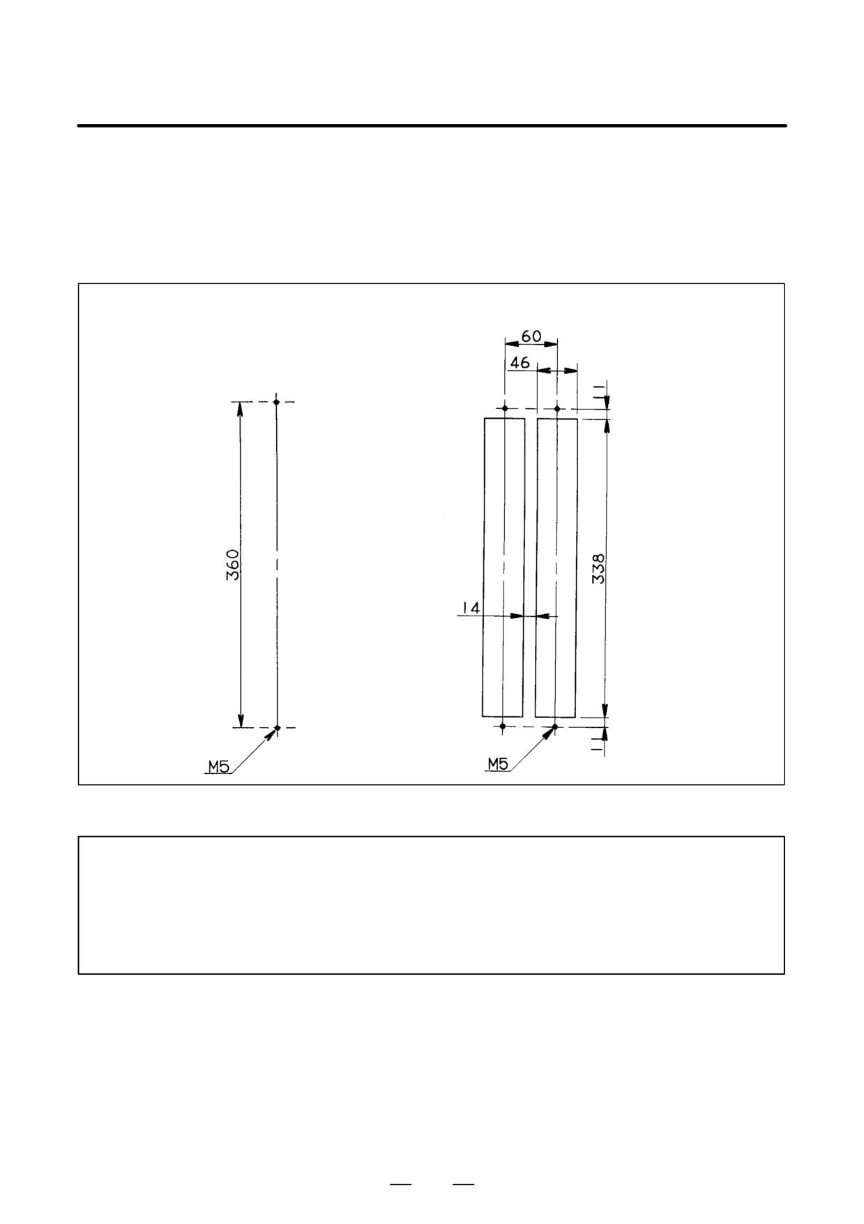
8.2
PANEL CUT-OUT
DIAGRAMS
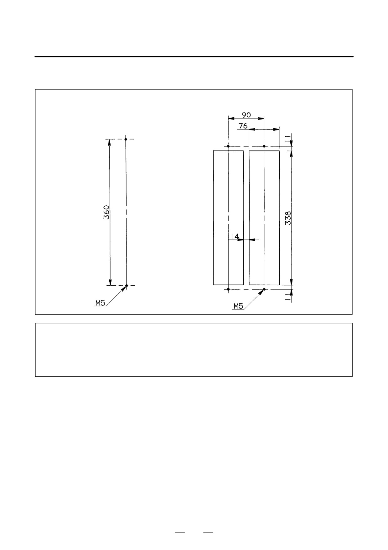
(a)
60-mm-wide amplifier
With no external fin
With external fin (when two units are installed side by side)
NOTE
1
When an external fin is provided, attach a packing (acrylonitrile-butadiene rubber, NBR [soft
type]) to the fin to protect it against oil and dust.
2
Reinforce the right and left sides of the panel cut-out in the power magnetics cabinet by using
fittings such as angles to maintain satisfactory contact between the sheet metal of the power
magnetics cabinet and the flange of the amplifier.
194
8. EXTERNAL DIMENSIONS AND
B-65162E/03
MAINTENANCE AREA
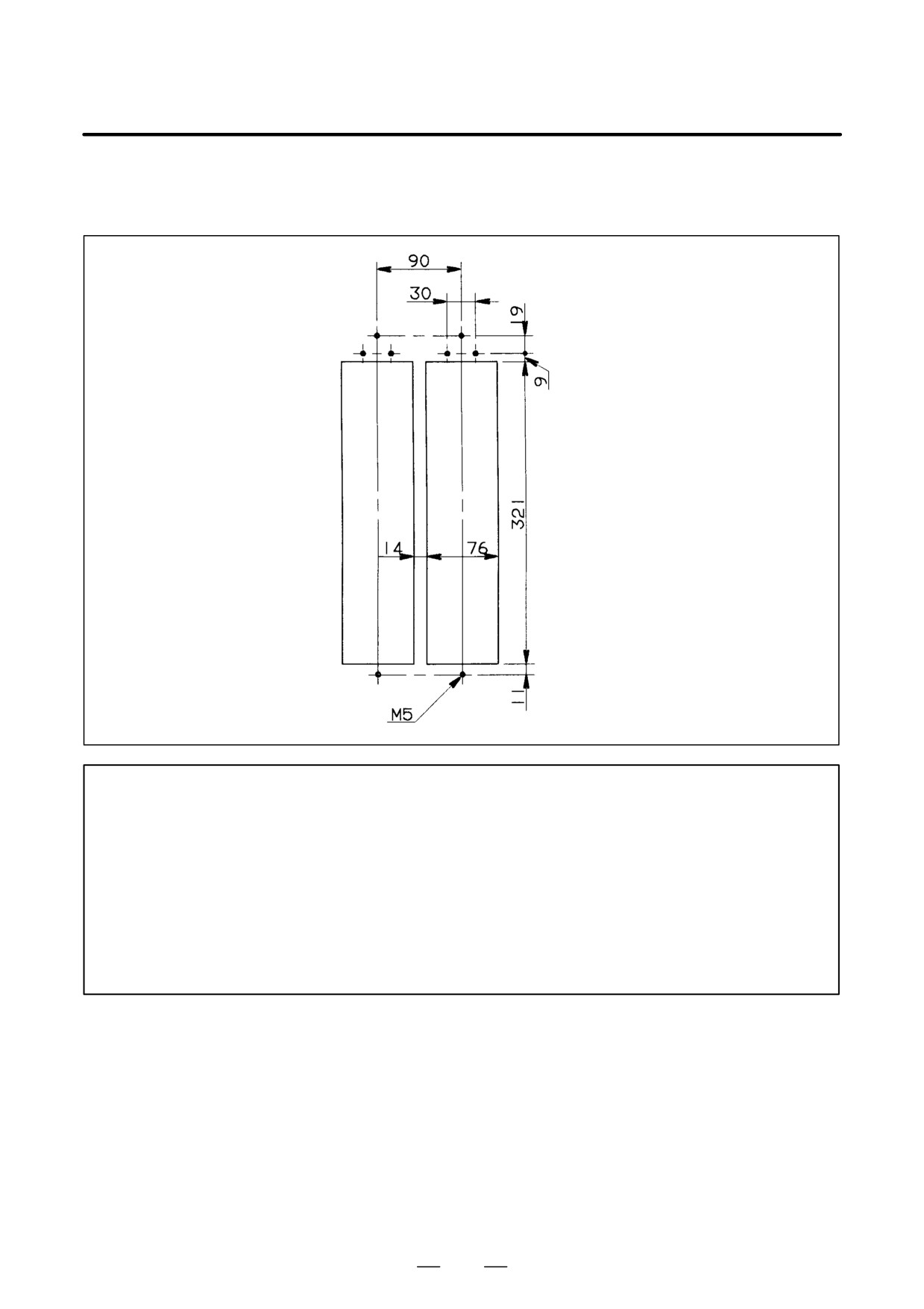
(b)
90-mm-wide amplifier (when no forced air cooling is required)
With no external fin
With external fin (when two units are installed side by side)
NOTE
1
When an external fin is provided, attach a packing (acrylonitrile-butadiene rubber, NBR [soft
type]) to the fin to protect it against oil and dust.
2
Reinforce the right and left sides of the panel cut hole in the power magnetics cabinet by using
fittings such as angles to maintain satisfactory contact with the amplifier.
195
8. EXTERNAL DIMENSIONS AND
MAINTENANCE AREA
B-65162E/03
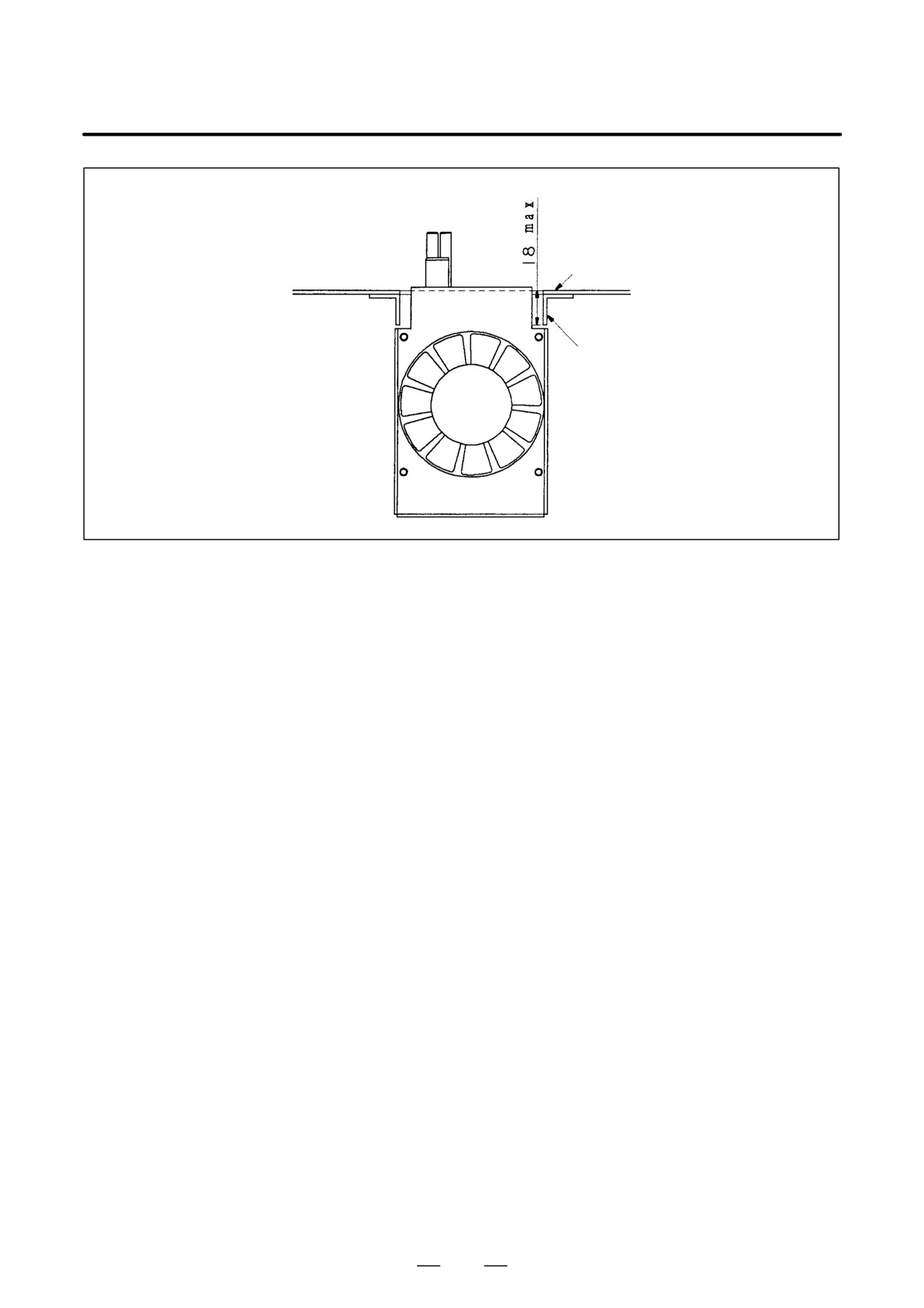
(c)
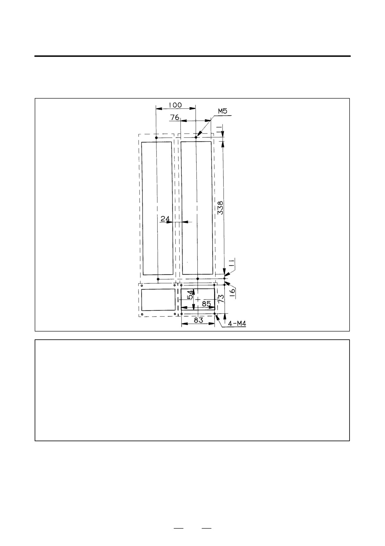
90-mm-wide amplifier (when fan adaptor A06B-6078-K001 is installed in PSM-11, SPM-11, and
SPM-11HV; two units are installed side-by-side)
NOTE
1
The above panel cut-out drawing is used when a fan adaptor for forced air cooling is used.
When a fan motor for forced air cooling is provided by the user, the same panel cut-out drawing
as (b) is used.
2
Attach a packing (acrylonitrile-butadiene rubber, NBR [soft type]) for protection against oil and
dust.
3
Reinforce the right and left sides of the panel cut hole in the power magnetics cabinet by using
fittings such as angles to maintain satisfactory contact with the amplifier.
(When the fan adaptor is used, the depth of the angle must be 18 mm or less to prevent
interference with the outer shape of the adaptor.)
196
8. EXTERNAL DIMENSIONS AND
B-65162E/03
MAINTENANCE AREA
Panel cut plane
Angle for reinforcement
197
8. EXTERNAL DIMENSIONS AND
MAINTENANCE AREA
B-65162E/03
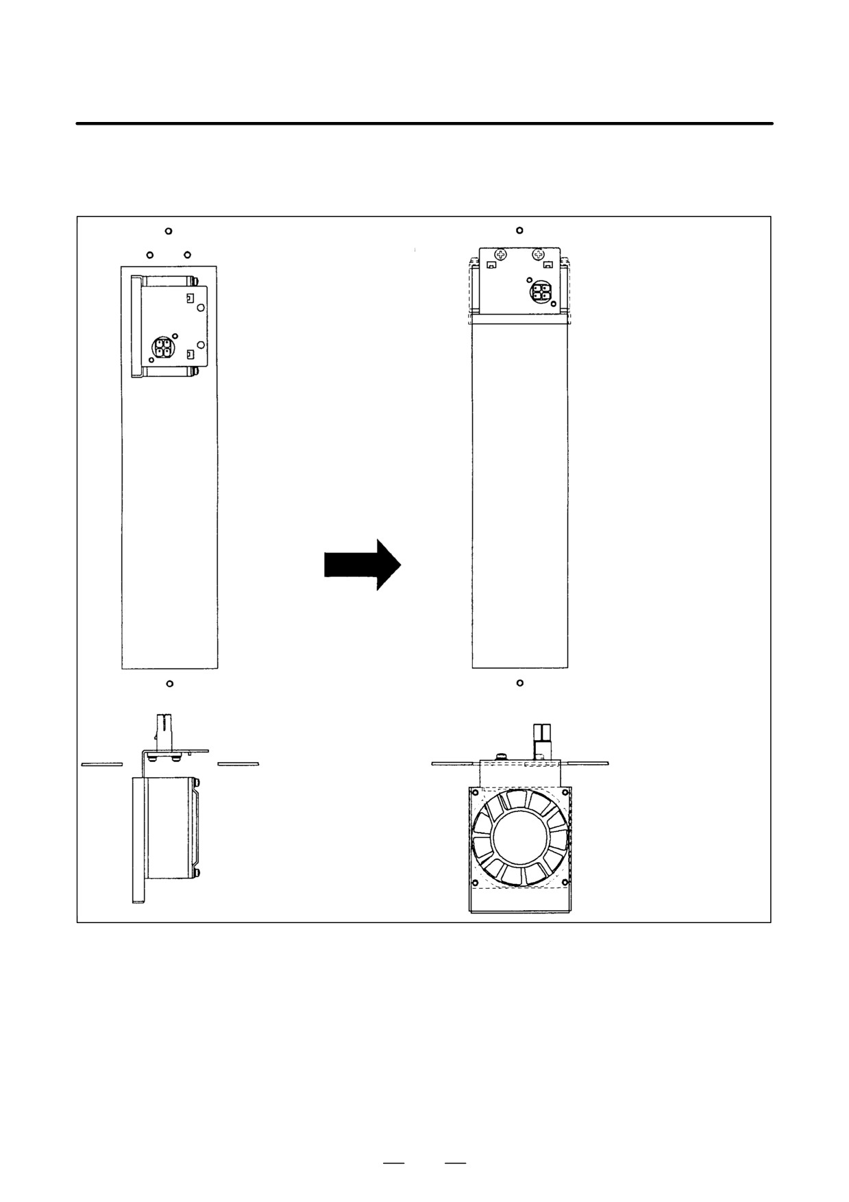
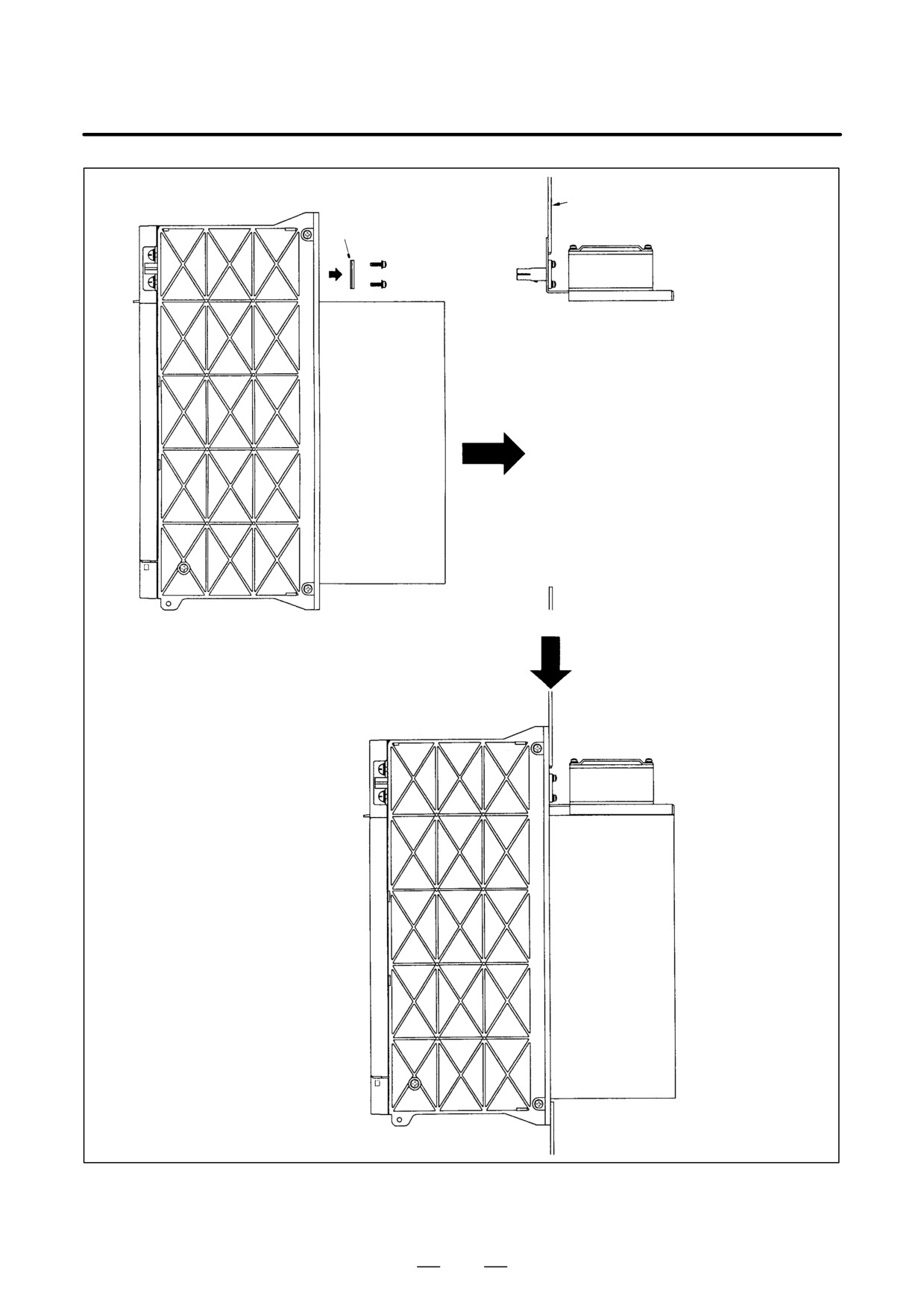
Installing a fan adaptor
A06B-6078-K001 (For PSM-11, SPM-11, and SPM-11HV)
Insert the fan adaptor in
Turn the fan adaptor
the amplifier mounting
through 90_, and retain
hole.
the adaptor on the panel
cut plane of the cabinet
by using M5 screws.
198
8. EXTERNAL DIMENSIONS AND
B-65162E/03
MAINTENANCE AREA
Panel cut plane
Sheet metal
Remove the sheet metal from the
amplifier as shown in the figure on
the left, and install the amplifier in
the cabinet.
The fan adaptor and amplifier
are internally connected.
Completed
199
8. EXTERNAL DIMENSIONS AND
MAINTENANCE AREA
B-65162E/03
(d)
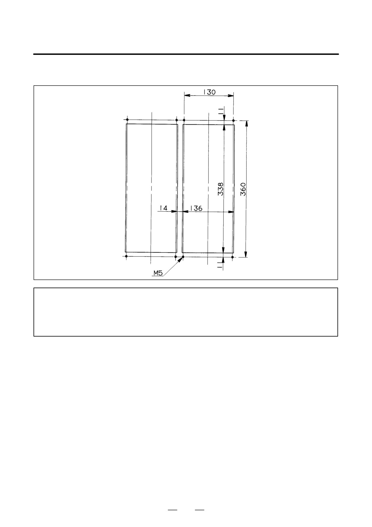
90-mm-wide amplifier (when fan adaptor A06B-6078-K002 is installed in SVM1-130 and SPMC-11; two
units are installed side-by-side)
NOTE
1
The above panel cut-out drawing is used when a fan adaptor for forced air cooling is used.
When forced air cooling is to be performed without using FANUC’s fan adaptor, the same panel
cut-out drawing as (b) is used.
2
When two fan adaptors (A06B-60780K002) are installed side-by-side (for example, when
SPMC-11 and SVM1-130 are used), separate the modules by at least 100 mm. A short bar
(F) can be used when the modules are separated from each other by 100 mm.
3
Attach a packing (acrylonitrile-butadiene rubber, NBR [soft type]) for protection against oil and
dust.
4
Reinforce the right and left sides of the panel cut-out in the power magnetics cabinet by using
fittings such as angles to maintain satisfactory contact with the amplifier.
200
8. EXTERNAL DIMENSIONS AND
B-65162E/03
MAINTENANCE AREA
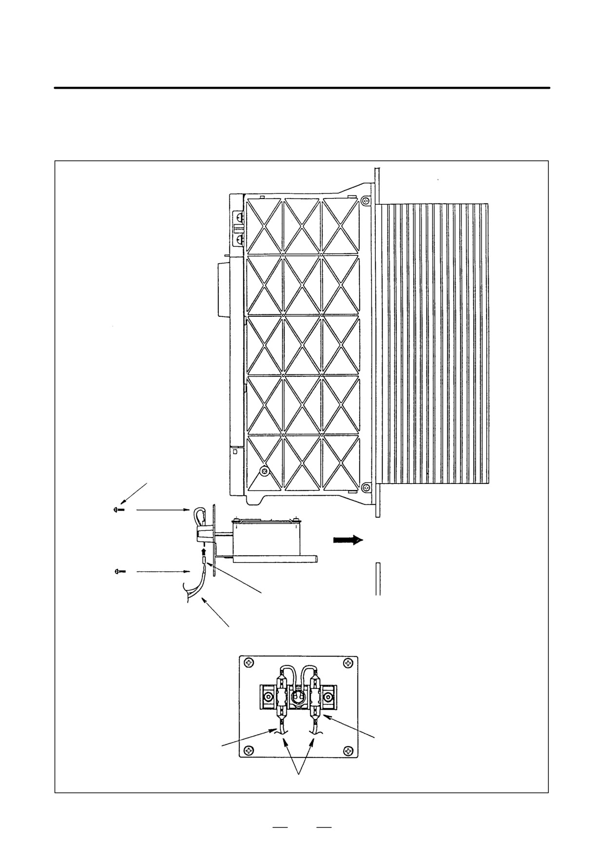
Installing a fan adaptor
A06B-6078-K002 (For SVM1-130 and SPMC-11)
Screw 4 M4
Install the fan adaptor on the panel
cut plane by using M4 screws.
Receptacle: series 6.3mm (0.250 in)
Wire cross-sectional area: 1.25mm2
Receptacle: series 6.3mm (0.250 in)
Wire cross-sectional area: 1.25mm2
1φ AC200V INPUT
201
8. EXTERNAL DIMENSIONS AND
MAINTENANCE AREA
B-65162E/03
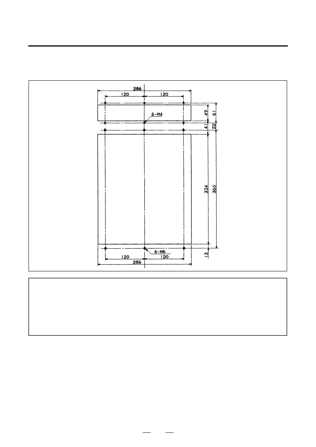
(e)
150-mm-wide amplifier (when two units are installed side-by-side)
NOTE
1
Attach a packing (acrylonitrile-butadiene rubber, NBR [soft type]) for protection against oil and
dust.
2
Reinforce the right and left sides of the panel cut-out in the power magnetics cabinet by using
fittings such as angles to maintain satisfactory contact with the amplifier.
202
8. EXTERNAL DIMENSIONS AND
B-65162E/03
MAINTENANCE AREA
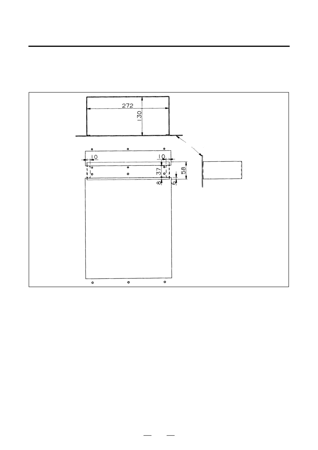
(f)
300-mm-wide amplifier (when fan adaptor A06B-6078-K003 is installed in PSM-45, SPM-45, PSM-75HV,
and SPM-75HV)
NOTE
Attach a packing (acrylonitrile-butadiene rubber, NBR [soft type]) for protection against oil and
dust.
Reinforce the right and left sides of the panel cut hole in the power magnetics cabinet by using
fittings such as angles to maintain satisfactory contact with the amplifier.
When this fan adaptor is used, a duct is always required. For the duct structure, see the
example given on the next page.
203
8. EXTERNAL DIMENSIONS AND
MAINTENANCE AREA
B-65162E/03
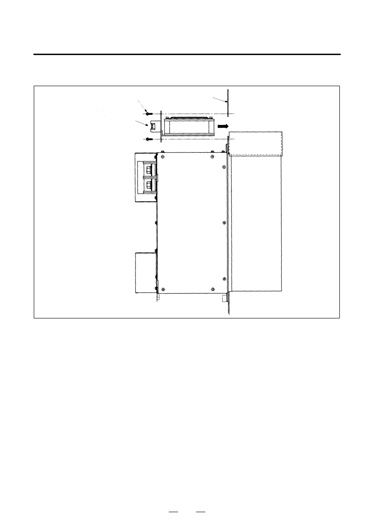
Example of a duct structure when FANUC’s fan adaptor (A06B-6078-K003) is used
To allow ventilation, install a duct shown below between the fan adaptor and heatsink. Weld the duct to the
cabinet.
Attaching plane
204
8. EXTERNAL DIMENSIONS AND
B-65162E/03
MAINTENANCE AREA
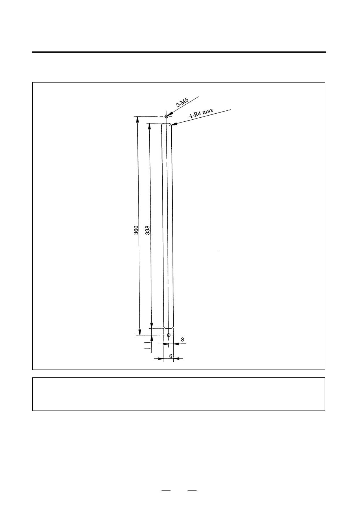
Installing fan adaptor A06B-6078-K003 (PSM-45, SPM-45, PSM-75HV, and SPM-75HV)
Screw 6-M4
10
Panel cut plane
AC200V IN
Applicable wire: 1.25mm2
Applicable crimp terminal: 1.25-4
205
8. EXTERNAL DIMENSIONS AND
MAINTENANCE AREA
B-65162E/03
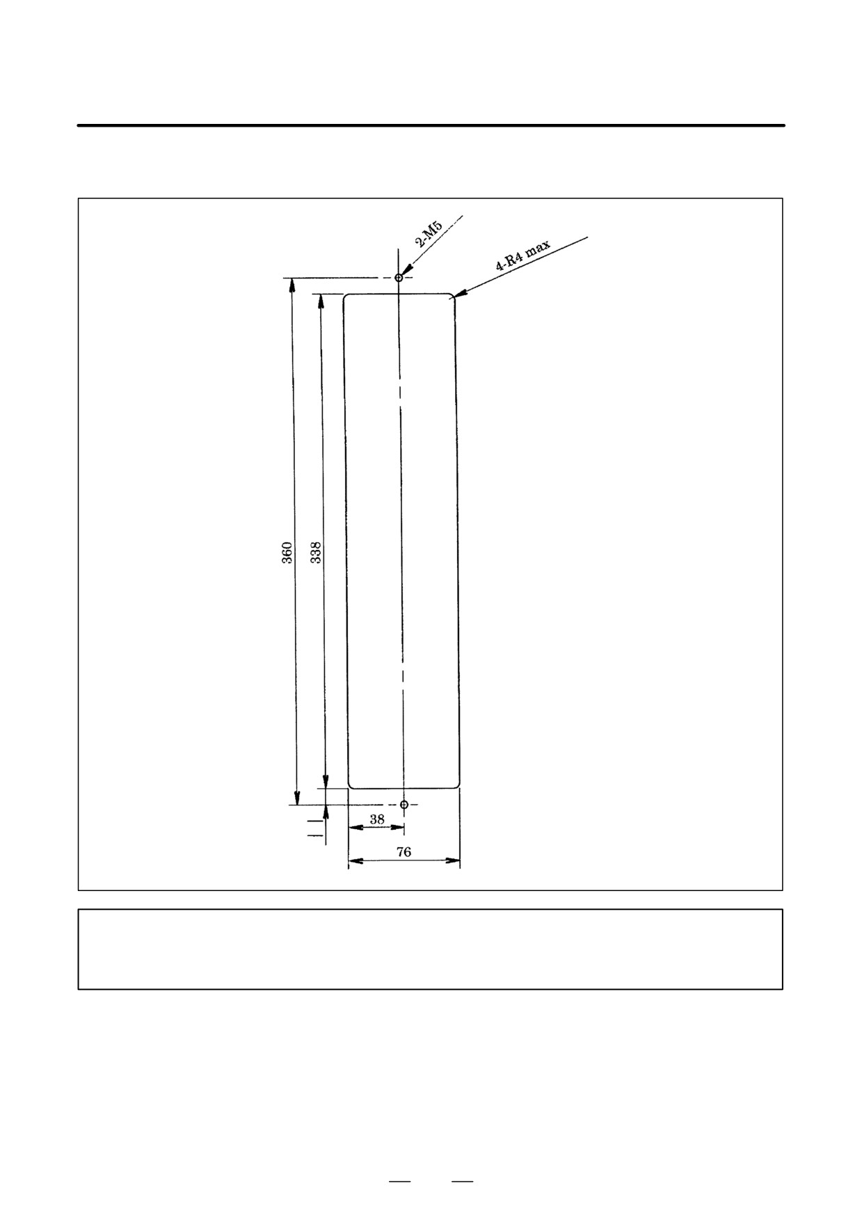
(g) Regenerative discharge unit (A06B-6089-H510)
NOTE
Attach a packing (acrylonitrile-butadiene rubber, NBR [soft type]) for protection against oil and
dust.
206
8. EXTERNAL DIMENSIONS AND
B-65162E/03
MAINTENANCE AREA
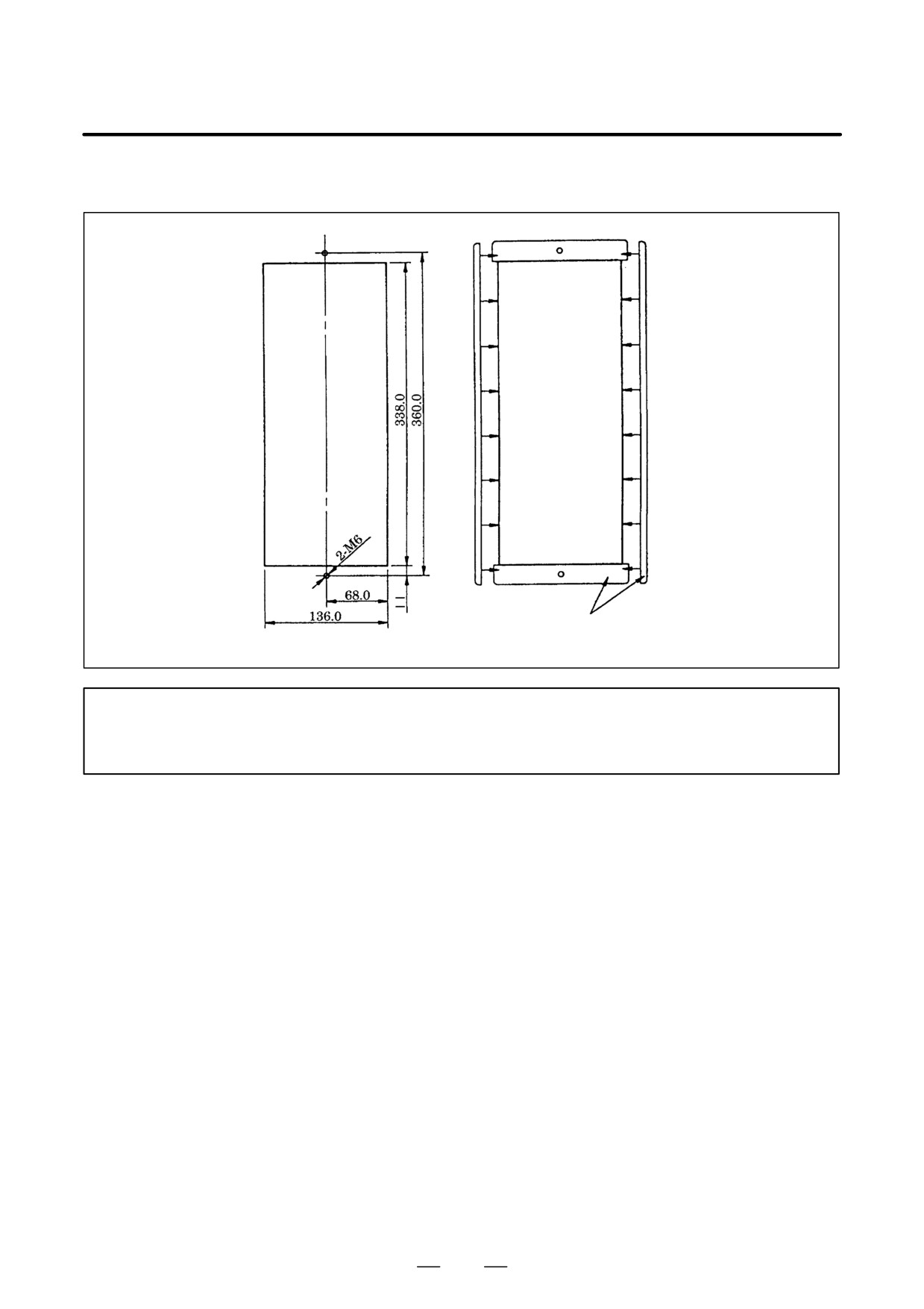
(h) Regenerative discharge unit (A06B-6089-H500)
NOTE
Attach a packing (acrylonitrile-butadiene rubber, NBR [soft type]) for protection against oil and
dust.
207
8. EXTERNAL DIMENSIONS AND
MAINTENANCE AREA
B-65162E/03
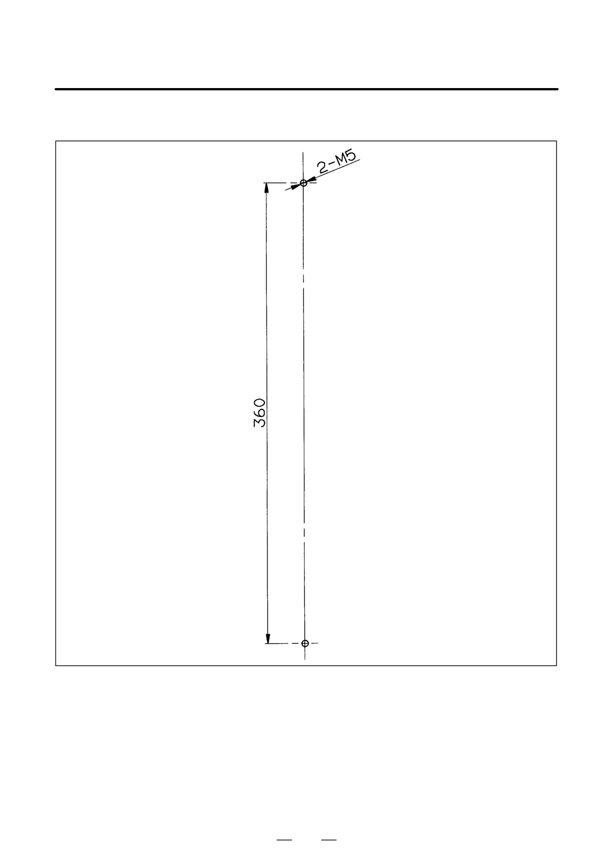
(i)
Regenerative discharge unit (A06B-6089-H711 to H713)
Panel cut
Packing (accessory)
Panel cut
NOTE
Attach a packing (acrylonitrile-butadiene rubber, NBR [soft type]) for protection against oil and
dust.
208
8. EXTERNAL DIMENSIONS AND
B-65162E/03
MAINTENANCE AREA
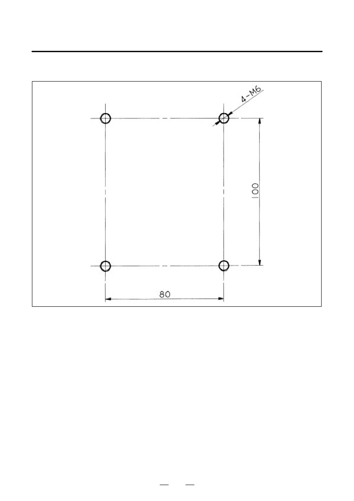
(j)
Dynamic brake module (A06B-6079-H410)
209
8. EXTERNAL DIMENSIONS AND
MAINTENANCE AREA
B-65162E/03
(k) AC reactor unit (A06B-6098-H001)
210
8. EXTERNAL DIMENSIONS AND
B-65162E/03
MAINTENANCE AREA
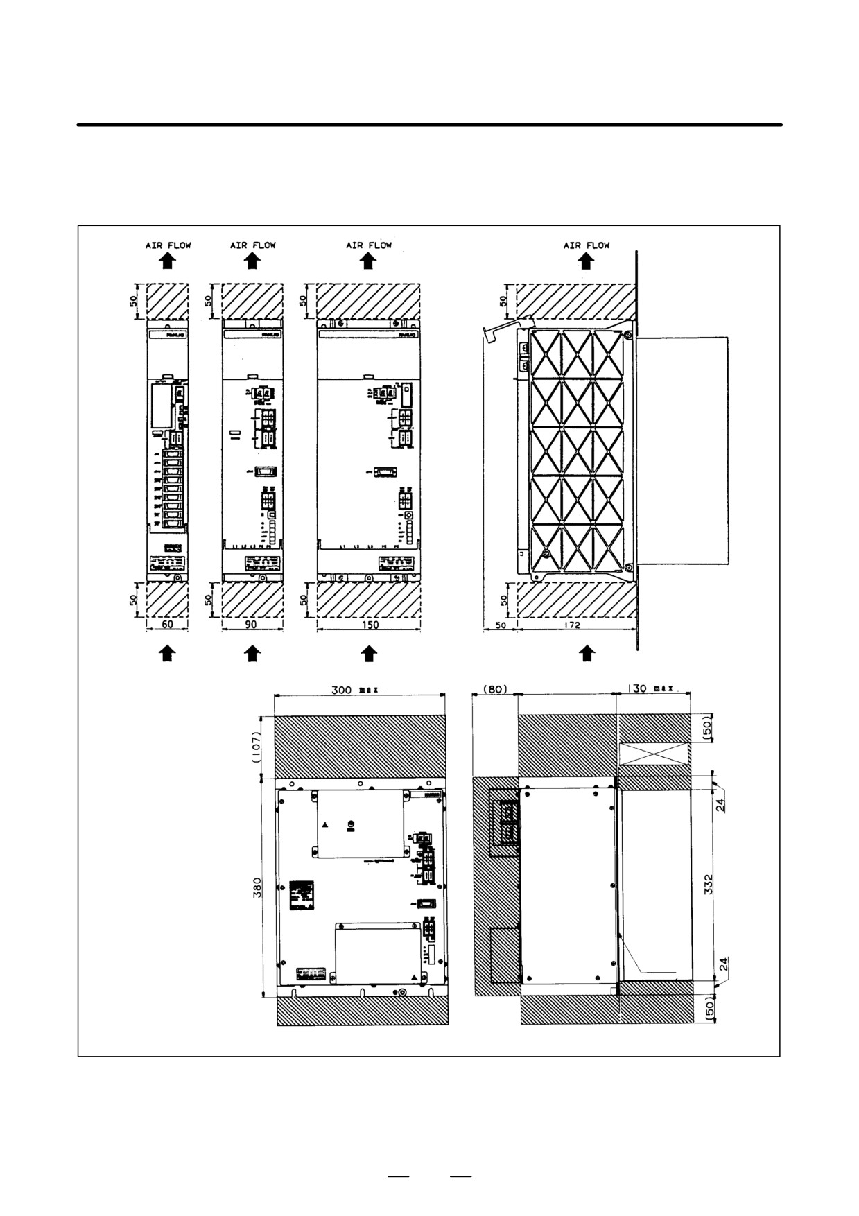
The amplifiers contain a fan motor to maintain an internal airflow. To
8.3
ensure that air can flow, the space indicated by shading in the figure below
MAINTENANCE
is required:
AREAS
172 (Note)
Space for ventilation
Space for ventilation Radiator cooling space
Cabling
Fan adaptor
space
Amplifier
Radiator
Mounting
plane
Space for ventilation
Space for ventilation
211
9. CONNECTION
B-65162E/03
CONNECTION
9
212