FANUC SERVO AMPLIFIER a series. DESCRIPTIONS (B-65162E/03) - page 5
B-65162E/03
5. INSTALLATION
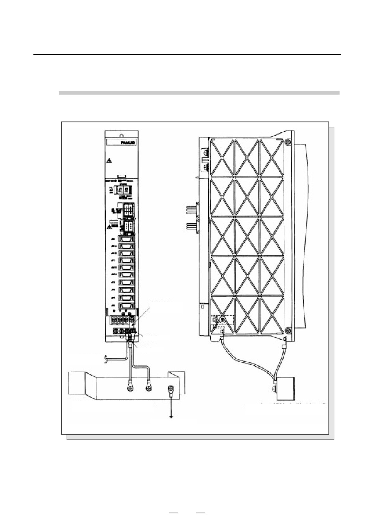
Ground Cable Connection (SPM-2.2, SPMC-2.2)
ÃÃÃÃ
Supplied
ground bar
M4 screw
M5 screw
Ã
Ãpower cableÃ
ÃÃÃÃÃ
ÃÃÃÃÃÃÃÃÃ
rame ground (FG) = cabinet
Frame ground (FG) = cabinet
ground plate
ground plate
ÃÃÃÃÃÃÃÃÃ
System ground
ÃÃÃÃÃÃÃÃÃ
ÃÃÃÃÃÃ
Fig.5.2.3 (k) Ground Cable Connection (SPM-2.2, SPMC-2.2)
123
5. INSTALLATION
B-65162E/03
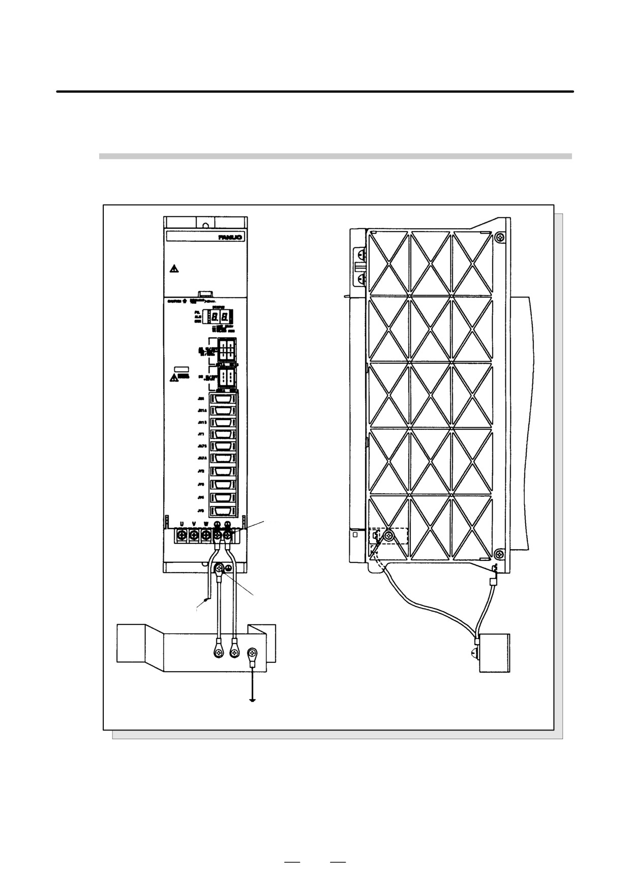
Ground Cable Connection (SPM-5.5, 11, 11HV, SPMC-5.5, 11)
M4 screw
From motor
M5 screw
power cable
ÃÃÃÃ
ÃÃÃÃÃÃÃÃÃÃ
ÃÃÃÃÃÃÃÃÃ
rame ground (FG) = cabinet
rame ground (FG) = cabinet
ground plate
ground plate
System ground
ÃÃÃÃÃÃÃÃÃ
ÃÃÃÃÃ
Fig.5.2.3 (l) Ground Cable Connection (SPM-5.5, 11, 11HV, SPMC-5.5, 11)
124
B-65162E/03
5. INSTALLATION
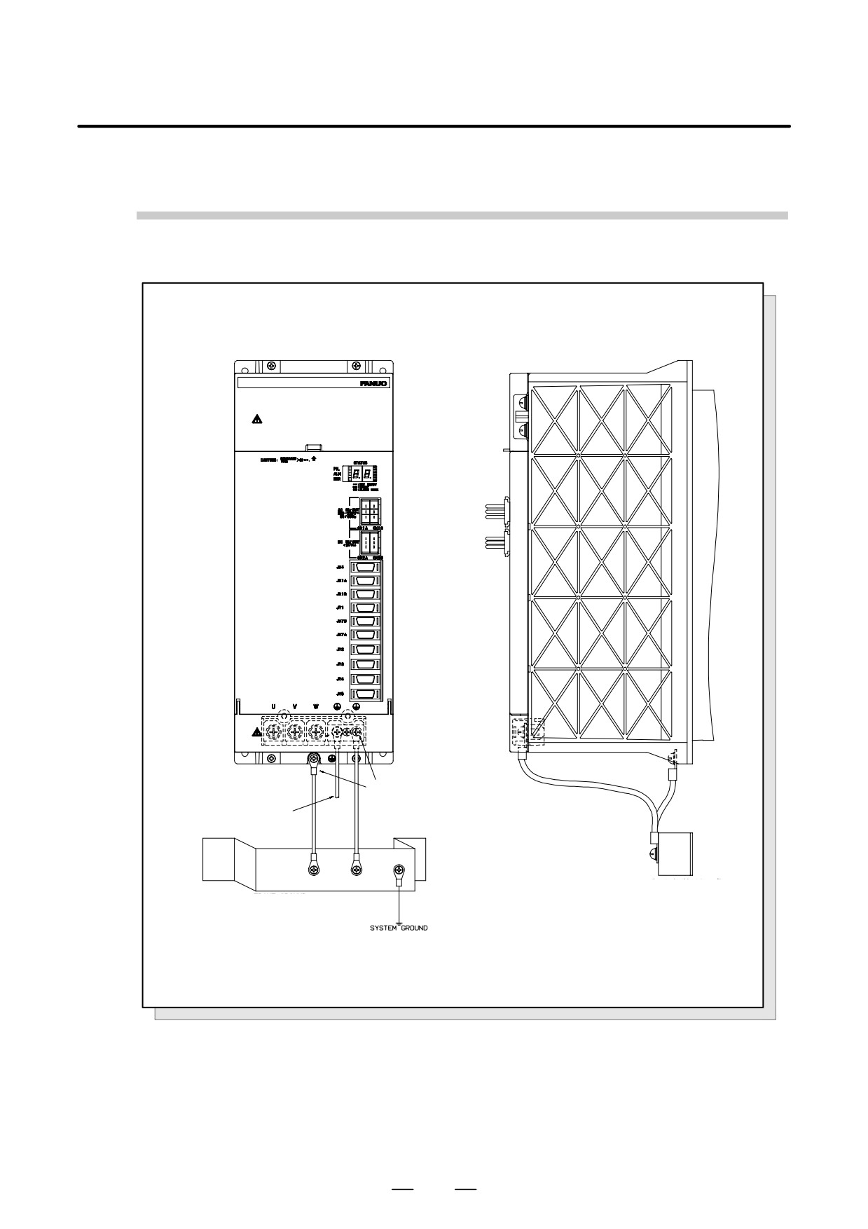
Spindle amplifier module SPM-15 to 30, 15HV to 45HV, SPMC-15 to 26
M5 screw
From motor
power lines
Frame ground (FG)
Frame ground (FG)
= ground plate of the cabinet
= ground plate of the cabinet
Fig.5.2.3 (m) Ground Cable Connection (SPM-15 to 30, 15HV to 45HV, SPMC-15 to 26)
125
5. INSTALLATION
B-65162E/03
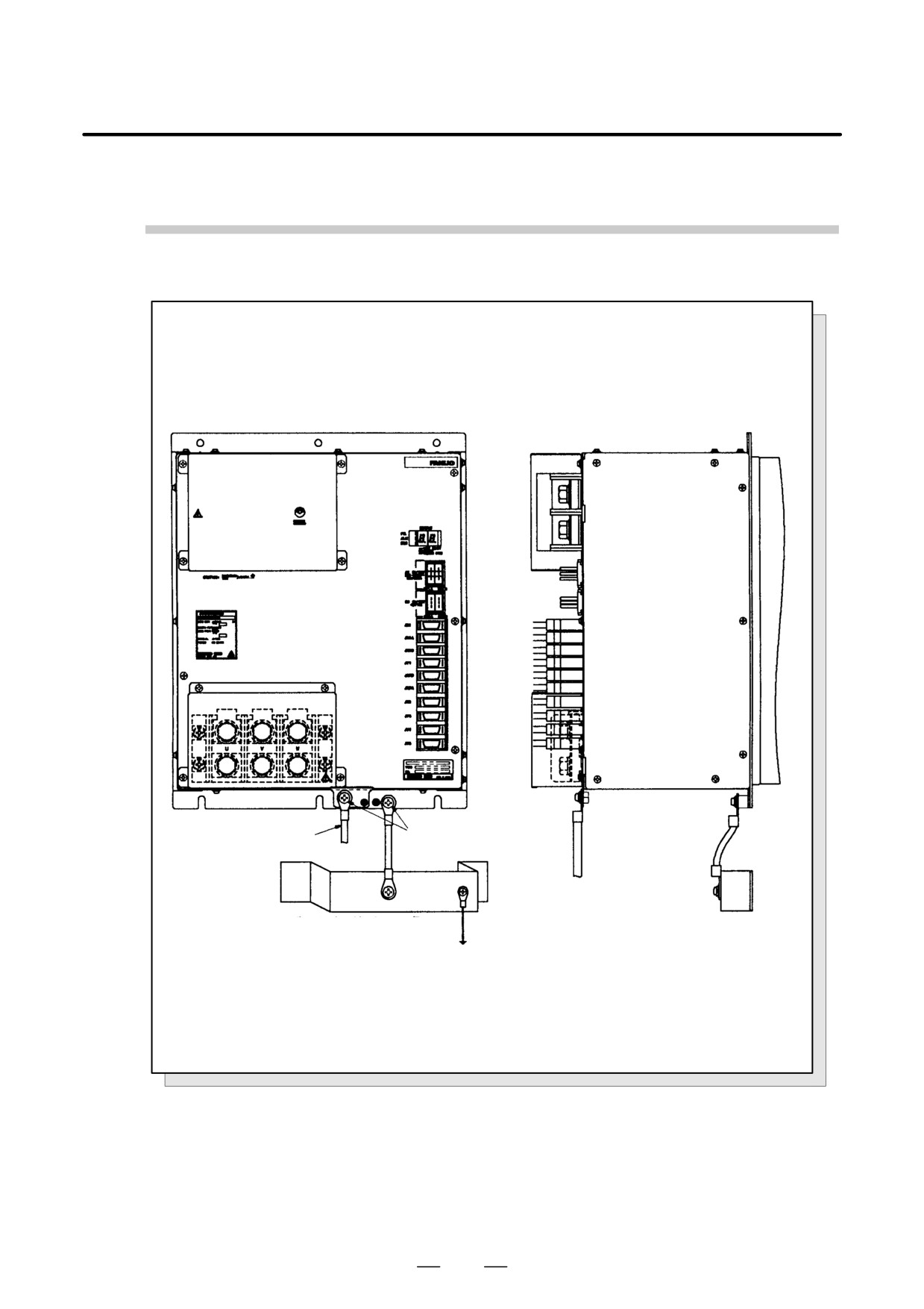
Ground Cable Connection (SPM-45, 75HV)
ÃÃÃÃ
From motor
6 screw
power cable
Ã
ÃÃÃÃ
ÃÃÃÃÃÃÃÃ
Frame ground (FG)
rame ground (FG)
= cabinet ground plate
= cabinet ground plate
Ã
ÃÃÃÃÃÃ
ystem ground
Fig.5.2.3 (n) Ground Cable Connection (SPM-45, 75HV)
126
B-65162E/03
5. INSTALLATION
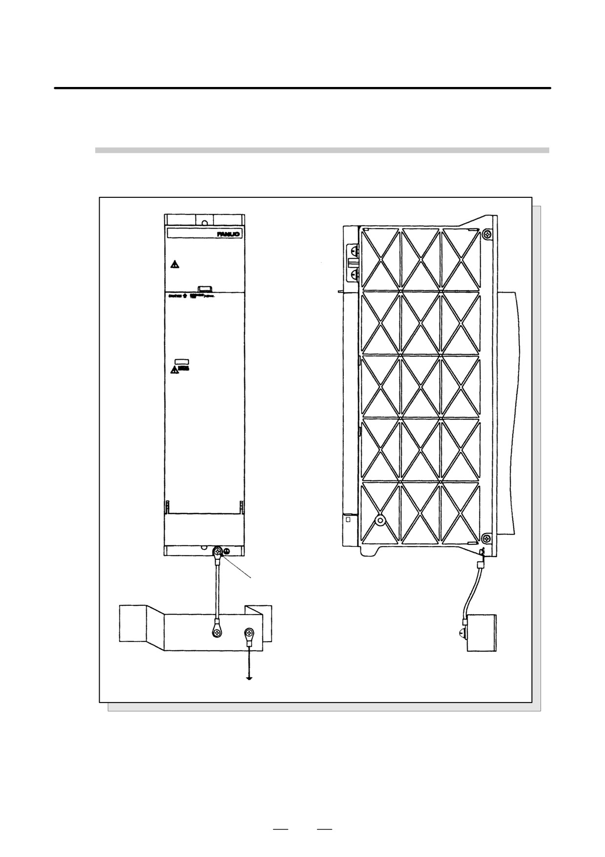
Ground Cable Connection (PSMC-18HV, 30HV)
M5 screw
Frame ground (FG) = cabinet
Ã
ÃFrame ground (FG) = cabinetÃÃ
round plate
round plate
Ã
ÃÃÃÃÃÃ
System ground
ÃÃÃÃÃÃ
Fig.5.2.3 (o) Ground Cable Connection (PSMC-18HV, 30HV)
127
5. INSTALLATION
B-65162E/03
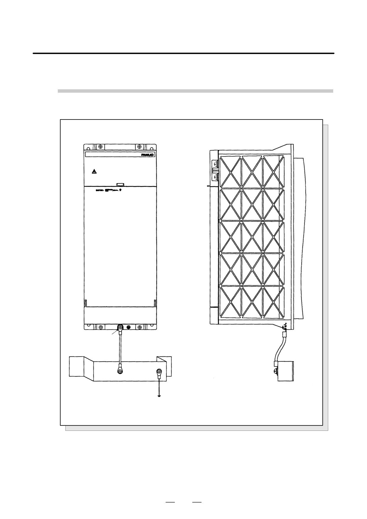
Ground Cable Connection (PSMC-45HV)
ÃÃÃÃ
5 screw
Ã
ÃÃÃÃÃÃÃÃÃ
ÃÃÃÃÃÃÃÃÃÃ
Frame ground (FG) = cabinet
ame ground (FG) = cabinet
ground plate
ground plate
System ground
ÃÃÃÃÃÃÃÃÃÃ
Fig.5.2.3 (p) Ground Cable Connection (PSMC-45HV)
128
B-65162E/03
5. INSTALLATION
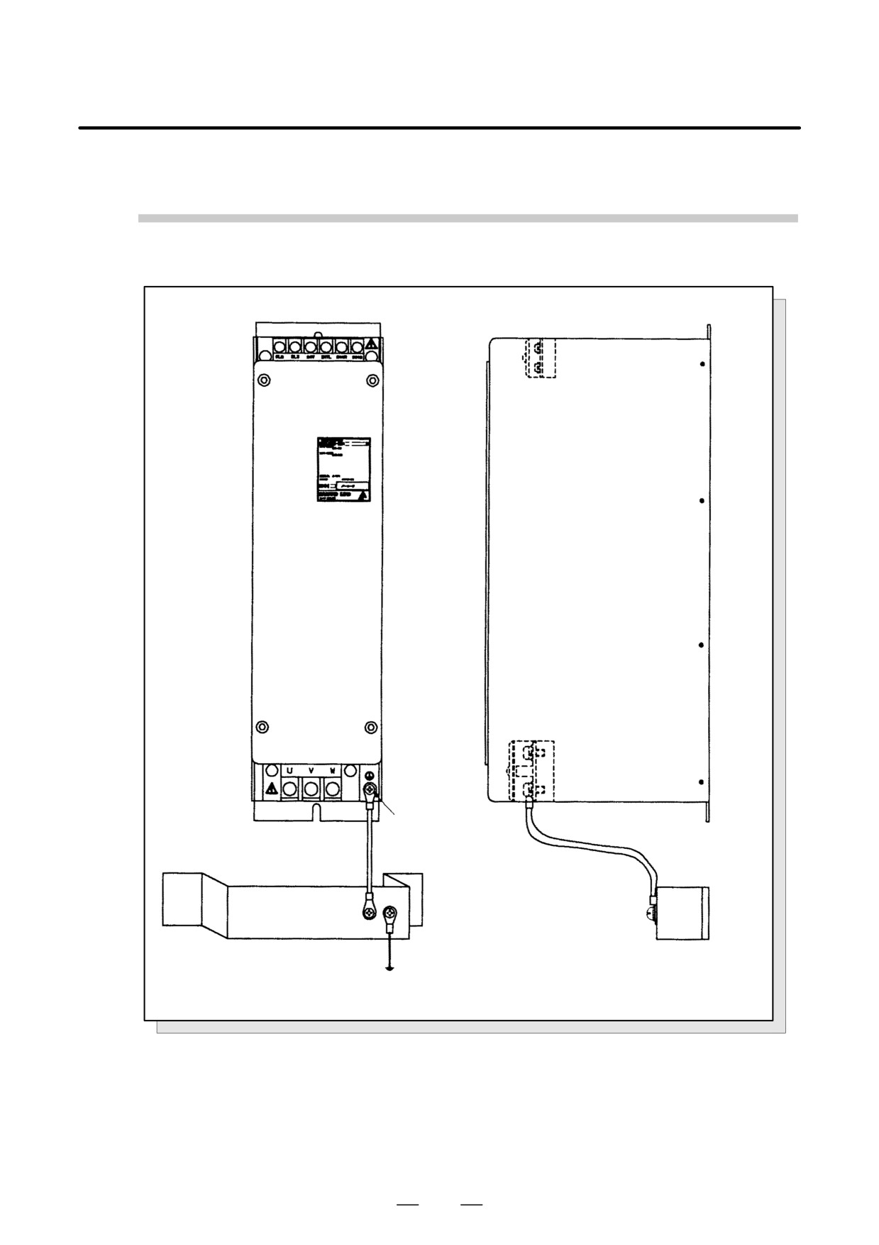
Ground Cable Connection (Dynamic Brake Module DBM)
M5 screw
ÃÃÃÃÃÃÃÃÃ
ÃÃÃÃÃÃÃÃÃÃ
Frame ground (FG) = cabinet
rame ground (FG) = cabinet
ground plate ÃÃÃÃÃ
Ã
ground plate
System ground
ÃÃÃÃÃÃÃ
ÃÃÃÃÃÃÃÃÃÃ
Fig.5.2.3 (q) Ground Cable Connection (Dynamic Brake Module DBM)
129
5. INSTALLATION
B-65162E/03
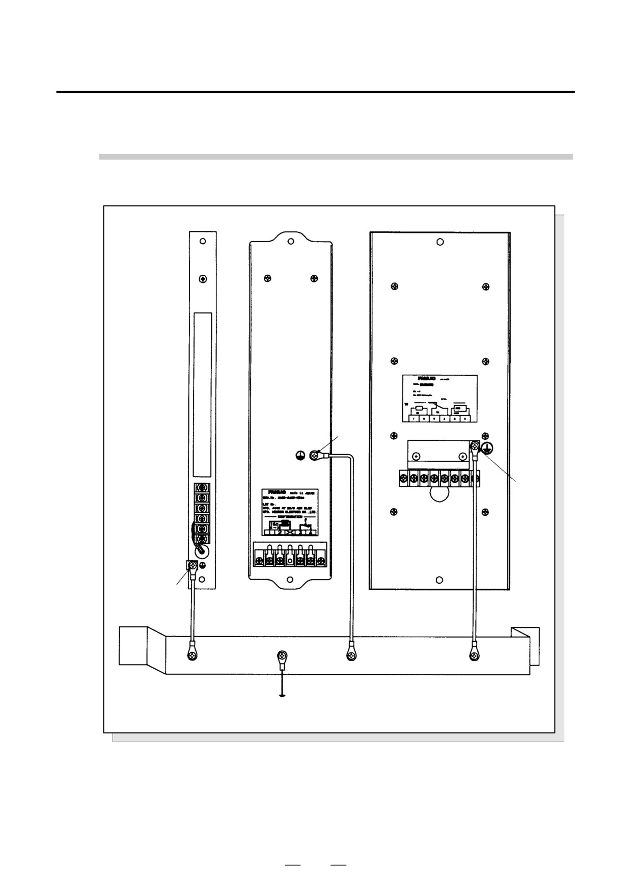
Ground Cable Connection (Resistance Discharge Unit)
A06B-6089-H510
A06B-6089-H500
A06B-6089-H711 to 713
M4ÃÃ
screw
ÃÃÃ
M4ÃÃ
screw
5 screw
Ã
Frame ground (FG) = cabinet
ground plate
ystem ground
Ã
ÃÃÃÃÃÃÃÃÃÃ
Fig.5.2.3 (r) Ground Cable Connection (Resistance Discharge Unit)
130
B-65162E/03
5. INSTALLATION
5.3
NOISE PREVENTION
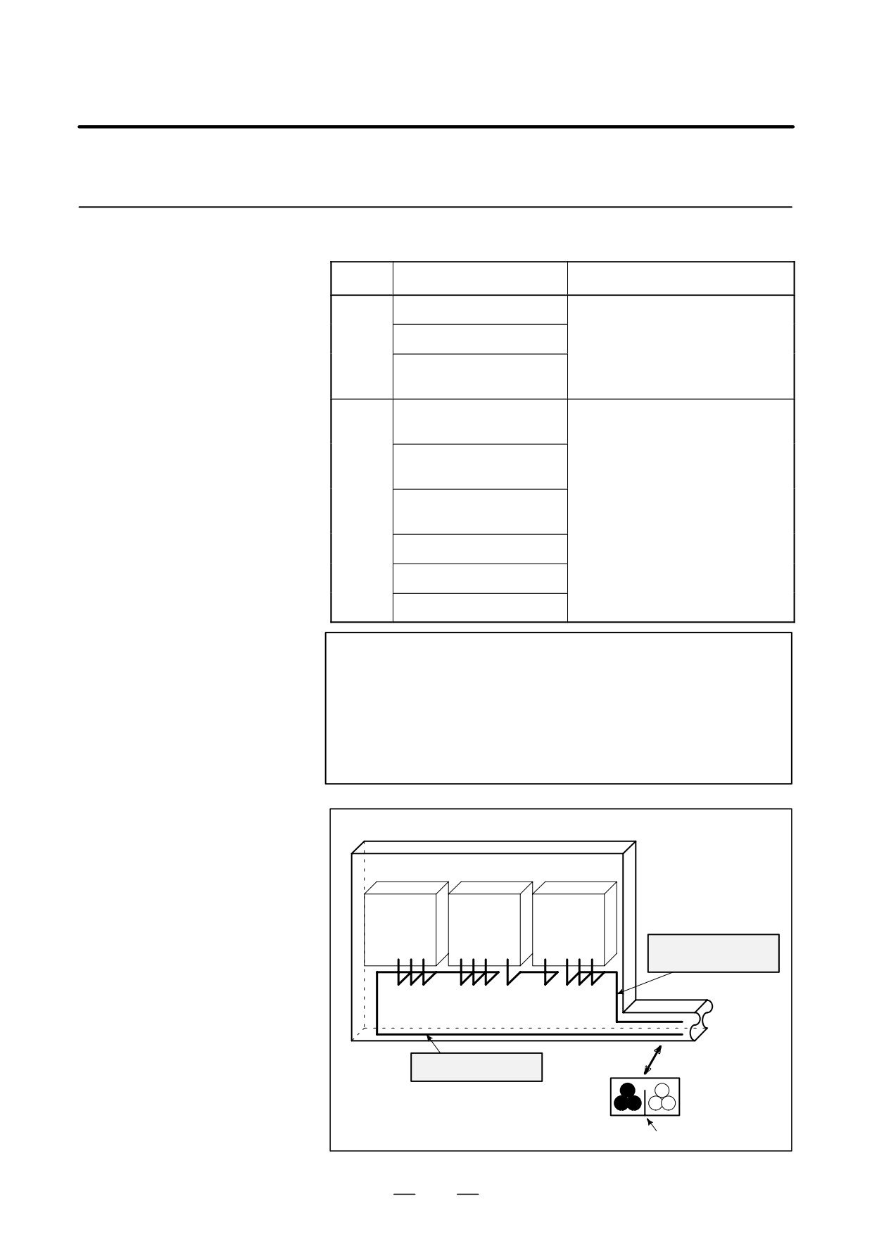
Signal lines must be separated from amplifier input power lines and motor
5.3.1
power lines. The table below lists the signal types.
Separation of Signal
Lines
Group
Signal type
Action
Amplifier input power line
Separate binding (Note 1) or electro-
Motor power line
A
magnetic shielding (Note 2) is neces-
sary for group B cables.
Magnetic contactor driving
coil (Note 3)
Cable between CNC and
SVM
Cable between CNC and
SPM
Separate binding or electromagnetic
Cable for position feedback
B
shielding is necessary for group A
or velocity feedback
cables. All cables must be shielded.
Cable for position coder
Cable for magnetic sensor
Other cable related to sensor
NOTE
1 The groups must be 10 cm or more apart from one another
when binding the cables in each group.
2 The electromagnetic shield refers to shielding between
groups with grounded steel plates.
3
Attach a noise suppressor such as a spark killer to the
magnetic contactor driving coil.
Cabinet
Spindle
Servo
Control
amp.
amp.
unit
Cable of group B
Duct
To operator’s
panel,
motor, etc.
Cable of group A
Section
Group A
Group B
Cover
131
5. INSTALLATION
B-65162E/03
5.3.2
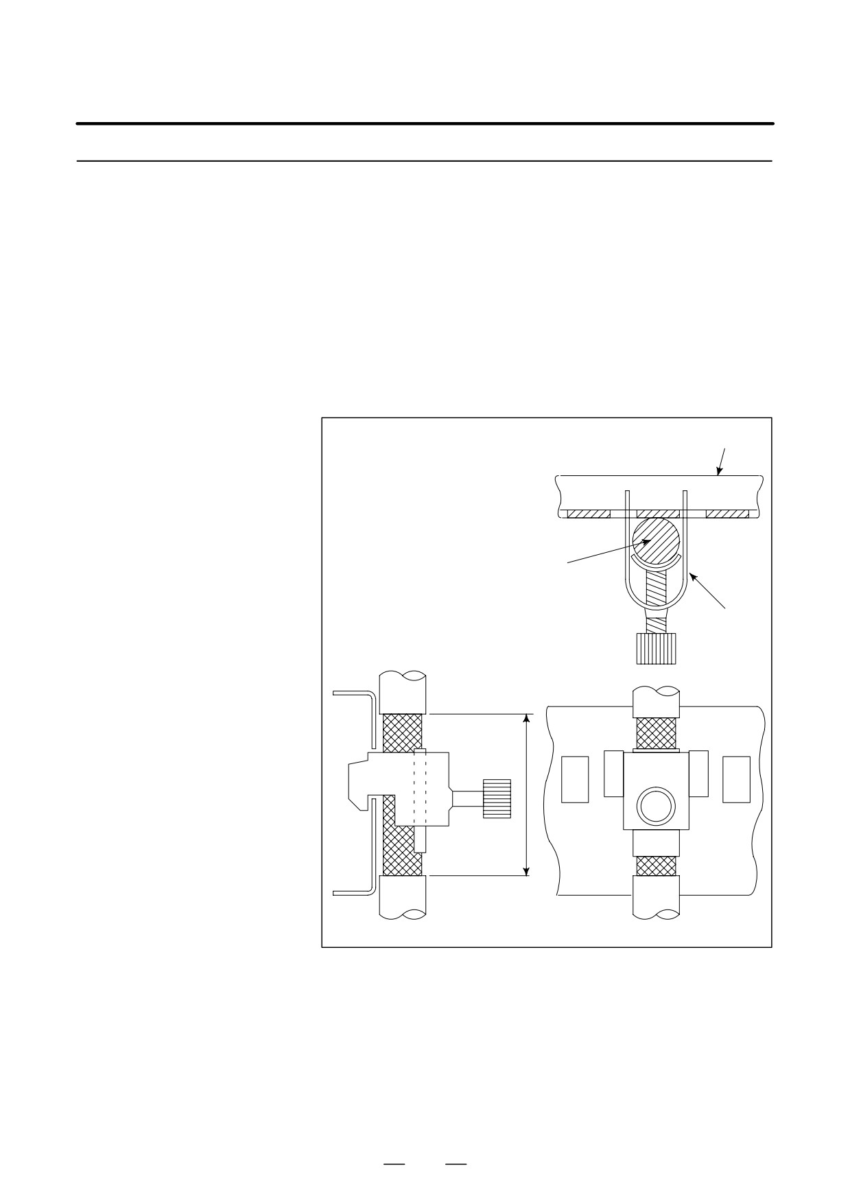
Perform terminal processing of the shield sheaths of the signal wires
according to the description in Section 9.2.
Cable Clamp and
The cables that run into the amplifier and which require shield processing,
Shield Processing
with the exception of K14, K15, K17, K18, K19, K31, and K33, must be
clamped as indicated in Fig. 5.3.2 (1). Clamping secures a cable and also
provides shielding. Clamping must always be performed since it is very
important for stable system operation.
Strip part of the cable jacket to expose the shield sheath, as shown in the
figure below. Secure that part of the cable to the ground plate by using
a clamp.
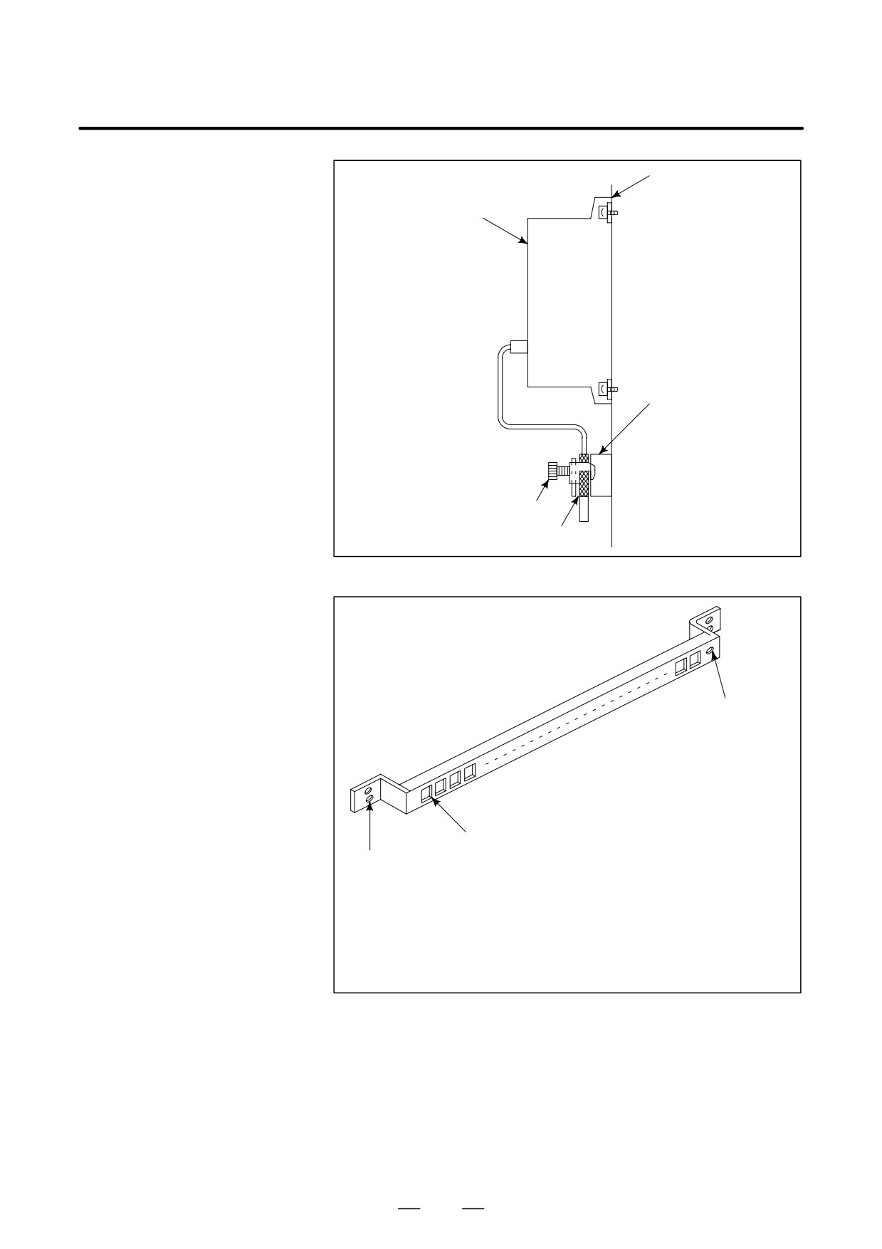
The ground plate must be created and installed by the user as shown in
Figs 5.3.2 (2), (3), (4), and (5).
Ground plate
Cable
Metal fittings
for clamp
40mm∼80mm
Fig.5.3.2 (a) Cable clamp (1)
132
B-65162E/03
5. INSTALLATION
Machine side
""
installation
""
board
Control unit
""
""
""
""
""
""
""
""
Ground plate
""
""
""
""
Metal fittings
""
for clamp
""
Shield cover
""
Fig.5.3.2 (b) Cable clamp (2)
Ground terminal
(grounded)
Hole for securing metal fitting clamp
Mount screw hole
Fig.5.3.2 (c) Ground plate
For the ground plate, use a metal plate of 2 mm or thicker, which surface is plated
with nickel.
133
5. INSTALLATION
B-65162E/03
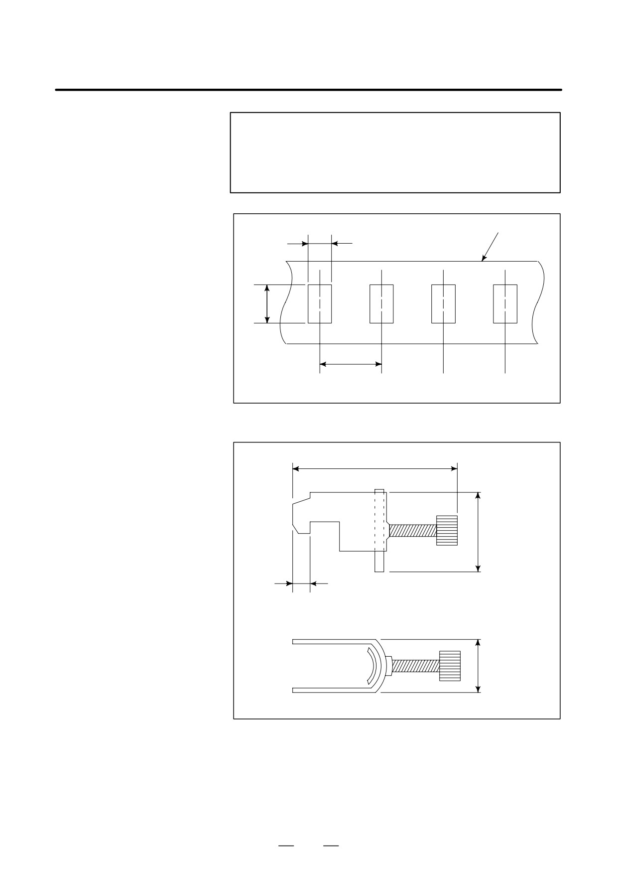
NOTE
Connect each shield cable to the ground plate installed near
the cabinet inlet by using a ground clamp. This prevents
noise generated in the panel from being emitted to external
devices.
Ground
8mm
plate
12mm
20mm
Fig.5.3.2 (d) Ground plate holes
Max. 55mm
28mm
6mm
17mm
Fig.5.3.2 (e) Outer drawings of metal fittings for clamp
134
B-65162E/03
5. INSTALLATION
5.3.3
Driving a servo motor or spindle motor may generate noise that could
affect external general electronic devices
(such as AM radios and
Protecting External
telephones).
Electronic Devices
Preventive measures against noise, including those for external electronic
from Noise
devices affected by noise, must be taken from the viewpoint of an entire
system. See Appendix G, which describes the principle of noise
generation and which provides examples of preventive measures.
5.3.4
CE marking requires compliance with the EMC Directive. FANUC’s
products have all been granted a certificate of conformity to the EMC
CE Marking
Directive (EC Directive 89/336/EEC) by a third-party certification
Requirements
organization.
For CE marking, special considerations are required to satisfy the
installation requirements described in the following guideline:
A-72937E: To satisfy the requirement of the EMC Directive
For details of the above guideline, contact your local FANUC office.
135
5. INSTALLATION
B-65162E/03
5.3.5
To satisfy the EMC Directive, the installation of a noise filter is required
in the input section of the power magnetics cabinet.
Selecting a Noise Filter
The rated current of the noise filter being used is determined according
to the type of the CNC that is connected, the type and number of motors,
and the power consumption of the other peripheral devices. Using the
expression given below, calculate the noise filter load current, and select
a noise filter so that the load current does not exceed the rated current of
the filter. Recommended noise filters are given in (12) of Section 2.2.3.
Obtaining the load current of a noise filter
The load current of a noise filter is the sum of the CNC input current, PSM
input current, and current consumption under the other loads.
Current con-
CNC input
PSM input
Load current
sumption under
=
current
+ Σ
current
+
(Arms)
other loads
(Arms)
(Arms)
(Arms)
(Note 1)
(Note 2)
NOTE
1
The CNC input current is determined by the number of
PSUs (power supply units). Calculate the CNC input current
from the following expression:
CNC input current (Arms) = 5 (Arms) x number of PSUs
Normally, a CNC has one PSU. The FS15 multiaxis control
system has two PSUs.
2
For details of how to obtain the PSM input current, see
Sections 4.1.1 or 4.2.1.
3
Attach a noise suppressor such as a spark killer to the
magnetic contactor driving coil. When more than one PSM
is connected, sum the input currents of the PSMs.
136
B-65162E/03
5. INSTALLATION
5.4
NOTES ON
AMPLIFIER
INSTALLATION
RELATED TO SAFETY
STANDARDS
5.4.1
The servo amplifier α series is designed to conform to the following
European safety standard:
Overview
DIN VDE 0160 1988/1:1989
(Electronic devices used in a power facility and their incorporation into
the facility)
To certify conformity to the standard, FANUC has obtained certification
from Tûv Rheinland, a third-party certification organization for
European standards.
In power magnetics cabinet design when the machine is to be CE-marked,
the installation conditions described in the following sections should be
considered carefully, based on the EC Machine Directives (directives
based on 89/392/EEC).
[Remarks]
CE marking requires compliance with a related EN standard [EN
60204-1] (Electric Devices in Industrial Machines, Part 1: General
Requirements).
If an EN standard (or an IEC standard if no EN standard exists) exists for
a component in the machine, the component must conform to that EN
standard.
At present, however, no EN standard (or IEC standard) is defined for
amplifiers. Based on the results of an investigation made by Tûv
Rheinland, an approved certification organization for the machine
directives, FANUC set the above VDE standard as a target standard and
designed the servo amplifier α series to conform to the standard.
Therefore, this amplifier series satisfies the amplifier requirements for CE
marking. The user can use these amplifiers without having to be
concerned about safety.
5.4.2
Standard Class of
(1) Insulation of circuits and protective ground
Insulation Design
According to DIN VDE 0160, the insulation design of this amplifier
series conforms to DIN VDE 0110 Part 1 and other related standards.
D The primary (power supply and main circuit) and the
secondary (control circuit) are separated from each other by
reinforced insulation.
D Basic insulation is used on the protective ground side.
137
5. INSTALLATION
B-65162E/03
Basic insulation is also used between the power supply main circuit
and aluminum flange (integrated with a heatsink). Connect the
protective ground wire to the ground terminal of the lower aluminum
flange as described in Section 5.2.3.
(2)
Installation category (overvoltage category)
DIN VDE 0110 [Insulation coordination of electric apparatuses]
classifies power supply facilities by the impulse voltage (relative to
ground) in the power supply to which the amplifier is connected.
This amplifier series is designed as a device of installation category
(overvoltage category) II.
The layout of this amplifier series has been designed on the
assumption that the rated impulse withstand voltage (impulse voltage
relative to ground) in the power supply to which the amplifier is
connected is 2.5 kV or lower.
If an impulse greater than 2.5 kV, relative to ground, appears in the
power supply, it must be suppressed.
Generally, this requirement is considered to be satisfied if an
insulated transformer is used in the power supply input section of a
machine.
If an insulated transformer is not used, install a surge protector
(lightning surge absorber) between the facility and ground to suppress
any impulse higher than 2.5 kV, relative to ground.
(3)
Contamination class of the installation environment and power
magnetics cabinet protection level
EN 60204-1 (13. Control devices/13.3 Protection level) requires
that, when a machine is installed in an environment equivalent to the
general plant level, the protection level against dust, coolant, chips,
and so forth be IP54 or higher.
For a power magnetics cabinet that satisfies this requirement, the
contamination class within the cabinet is considered to be class 2.
The insulation of this amplifier series has been designed on the
assumption that the amplifier is installed in an environment of
contamination class 2.
When using the amplifier in a general machine installation
environment, install the amplifier in a power magnetics cabinet that
satisfies the requirements of protection level IP54.
The IP level, however, depends on the environment (atmosphere) in
which a machine is installed. Select the protection level of the power
magnetics cabinet according to the environment.
For an external heatsink cooling type amplifier with a heatsink fin
protruding from the rear of the mounting flange, the fin section should
be in a cooling area
(duct) of about IP22 to
33, and special
considerations should be taken not to protect the fin from direct
coolant splashes or chips.
138
B-65162E/03
5. INSTALLATION
5.4.3
Protection Against
(1)
Protection against direct contact to a charged part
Electric Shock
The protection level against electric shock after the installation of this
amplifier series is equivalent to IP1X (hand protection). Thus, no live
part can be touched unconsciously or carelessly.
This amplifier series must always be installed in a power magnetics
cabinet. According to Item 6.2.1 of EN 60204-1 ”Electric Shock
Protection by Using a Cabinet,” lock the power magnetics cabinet so
that, while the amplifier is on, the cabinet cannot be opened by
persons except special maintenance personnel or a person qualified
for maintenance who has been trained in protective measures against
electric shock.
When a machine operator needs to open the power magnetics cabinet
to perform a certain operation, the operator must have received
sufficient safety education, or a protection cover must be installed to
prevent the operator from touching the amplifier.
(2)
Checking discharge of an electrolytic capacitor
This amplifier series contains a large-capacitance electrolytic
capacitor for the power supply smoothing circuit. Even after the
power supply input circuit is turned off, this capacitor remains
charged for a while.
When it proves necessary to touch the amplifier for maintenance and
so forth, do not start maintenance work immediately; wait for the
discharge time indicated on the face plate of the amplifier.
Alternatively, measure the residual voltage at the DC link section by
using a volt-ohm meter and check that the LED (red) for indicating
the charge state is off to ensure safety.
Standards define voltages exceeding 60 VDC as hazardous voltages.
(3)
Leakage current flowing to the protective ground wire
Motors are controlled by applying a voltage to the armature with the
mean amplitude and frequency of the voltage changed by pulse width
modulation. For this pulse width modulation, a chopper voltage is
applied to the power line of the motor to provide a carrier frequency
of several kilohertz.
Ground drift capacitance mainly between the motor armature
winding and case and between the power line of the motor power
cable and protective ground wire causes a leakage current to flow into
the protective ground wire of the motor power cable and the machine
ground. Part of the leakage current also flows into the protective
ground wire of the machine.
The resultant leakage current is about 1 to 2 mA per motor shaft at the
commercial power supply frequency
(50/60 Hz). With the
measurement circuit defined by EN 60950, the leakage current is
allowed to be much higher than 3.5 mA; this is because the
high-frequency component sensitivity cannot be fully reduced.
139
5. INSTALLATION
B-65162E/03
Unless a machine is grounded, touching the machine may cause
electric shock. Take one of the following protective measures against
electric shock:
(a) Use a protective ground wire with a copper wire cross-sectional
area of no less than 10 mm2.
(b) Install a ground fault interrupter so that the power supply can be
disconnected immediately if a ground fault occurs.
(c) Add a protective grounding terminal to the cabinet to make a
double ground wire connection.
When using a ground fault interrupter, select an electromagnetic
ground fault interrupter with a low high-frequency component
sensitivity, or an electronic ground fault interrupter that can be used
with inverters.
Amplifiers have multiple protective grounding terminals (marked as
5.4.4
defined by 417-IEC-5019). These terminals are used to prevent electric
Protective Installation
shock in case of dielectric breakdown, and are also used for functional
grounding to prevent noise.
All protective ground terminals must be connected to the protective
ground (PE) connection terminals in the power magnetics cabinet.
For how to connect the protective ground wires and the cross-sectional
areas of these wires, see Section 5.2.3.
Note that cables from cable terminals cannot be secured together with
protective ground terminals.
5.4.5
The amplifier uses IGBT (transistors) as an internal means of turning off
the power system; it does not use an electromechanical means.
Notes on the
Therefore, when an emergency stop circuit is configured, a line contactor
Emergency Stop
enabling electromechanical disconnection must be installed on the power
Circuit Configuration
input line for feeding power to the power supply module so that a voltage
is applied to the control coil of the contactor via the contactor control
output of the power supply module.
Some amplifier failures may prevent the output relay of the power supply
module from being turned off even when the amplifier emergency stop
command input (*ESP) is driven low, thus disabling disconnection by the
line contactor.
The emergency stop circuit must disconnect power without fail. It must
have a redundant circuit configuration having a route through which the
line contactor is disconnected directly by the command generated by the
emergency stop operation switch, independent of the disconnection
function provided by the amplifier.
If the power line is disconnected during spindle rotation when a spindle
amplifier module is used, the spindle may not be able to be stopped
immediately by the power regeneration function, and may keep rotating
by the force of inertia. Therefore, on the redundant circuit side, a delay
function must be provided which is based on an off-delay timer
considering a normal stop time.
140
B-65162E/03
5. INSTALLATION
For detailed notes on the safety circuits, refer to the following document:
A-71429-S13J : Safety Circuit Requirements and Configuration
Examples
To obtain this document, contact your local FANUC office.
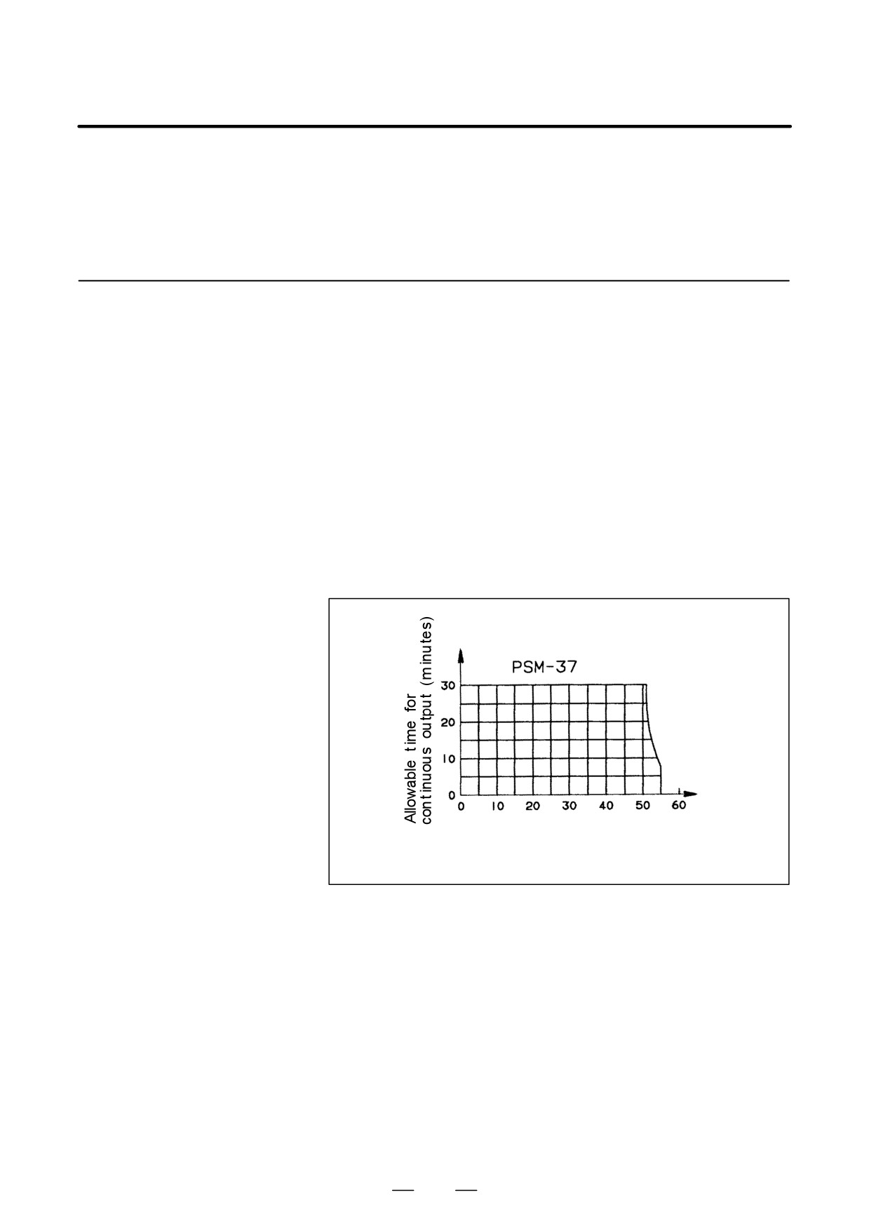
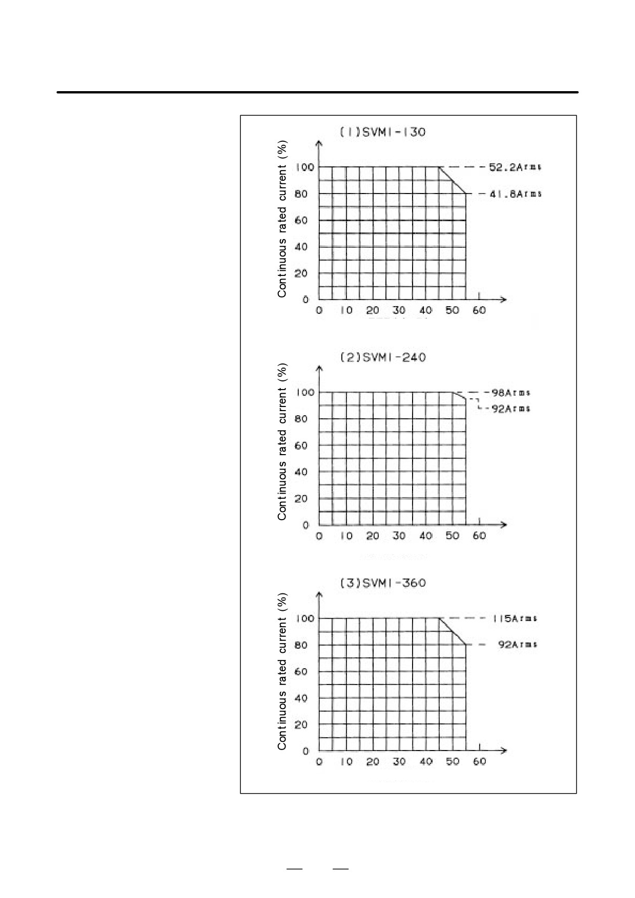
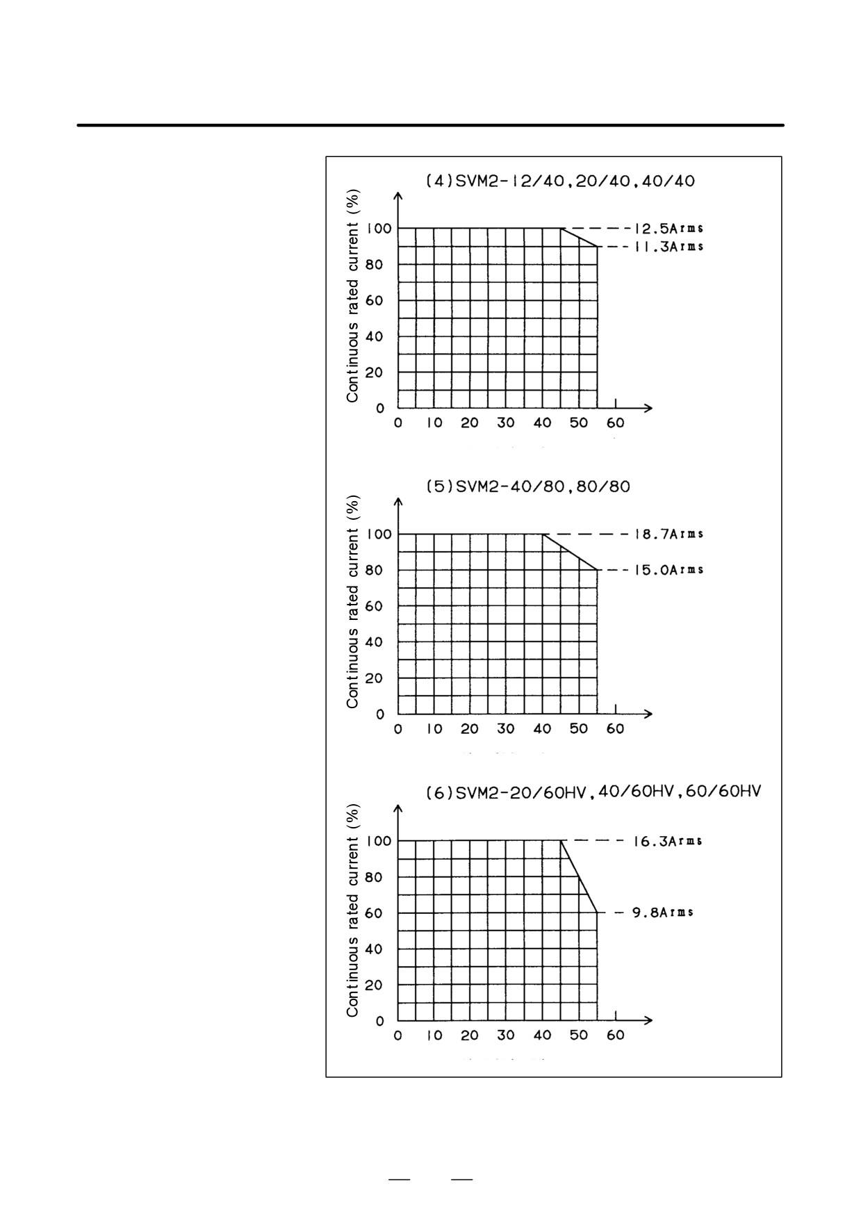
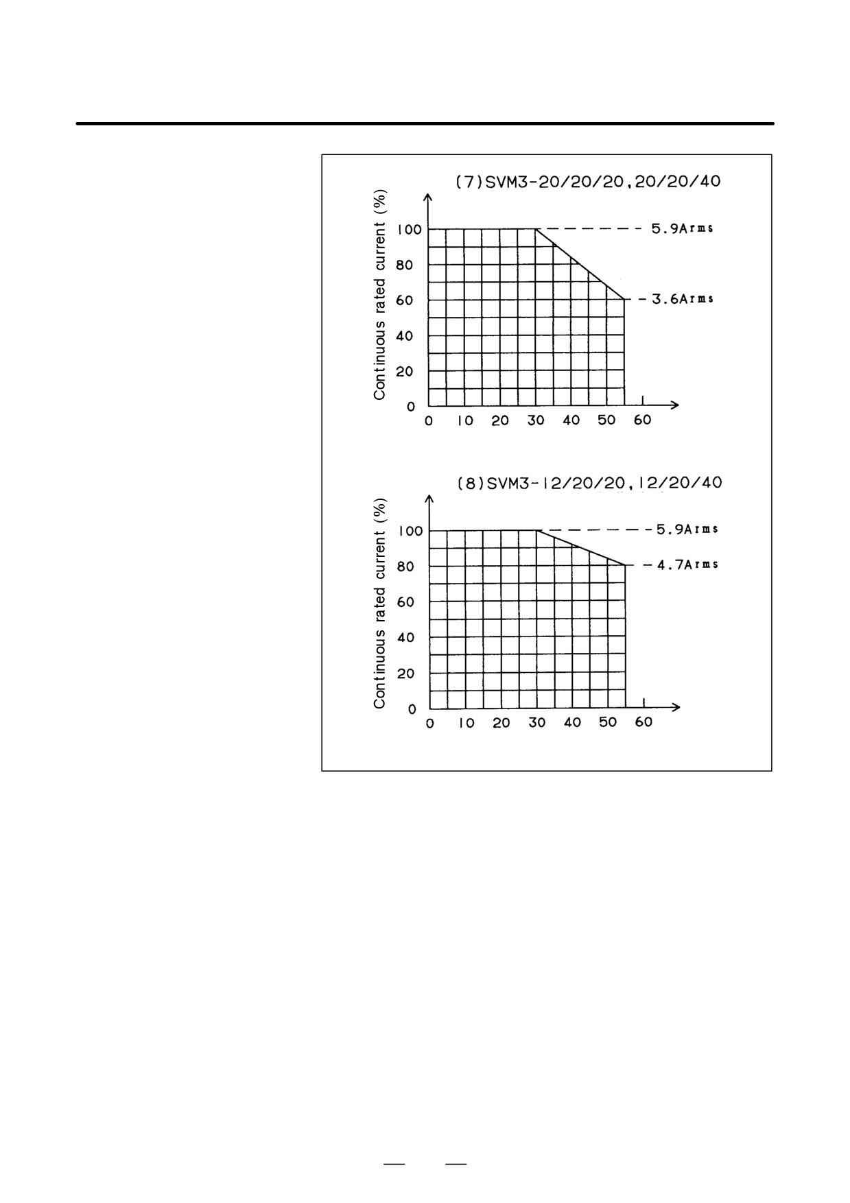
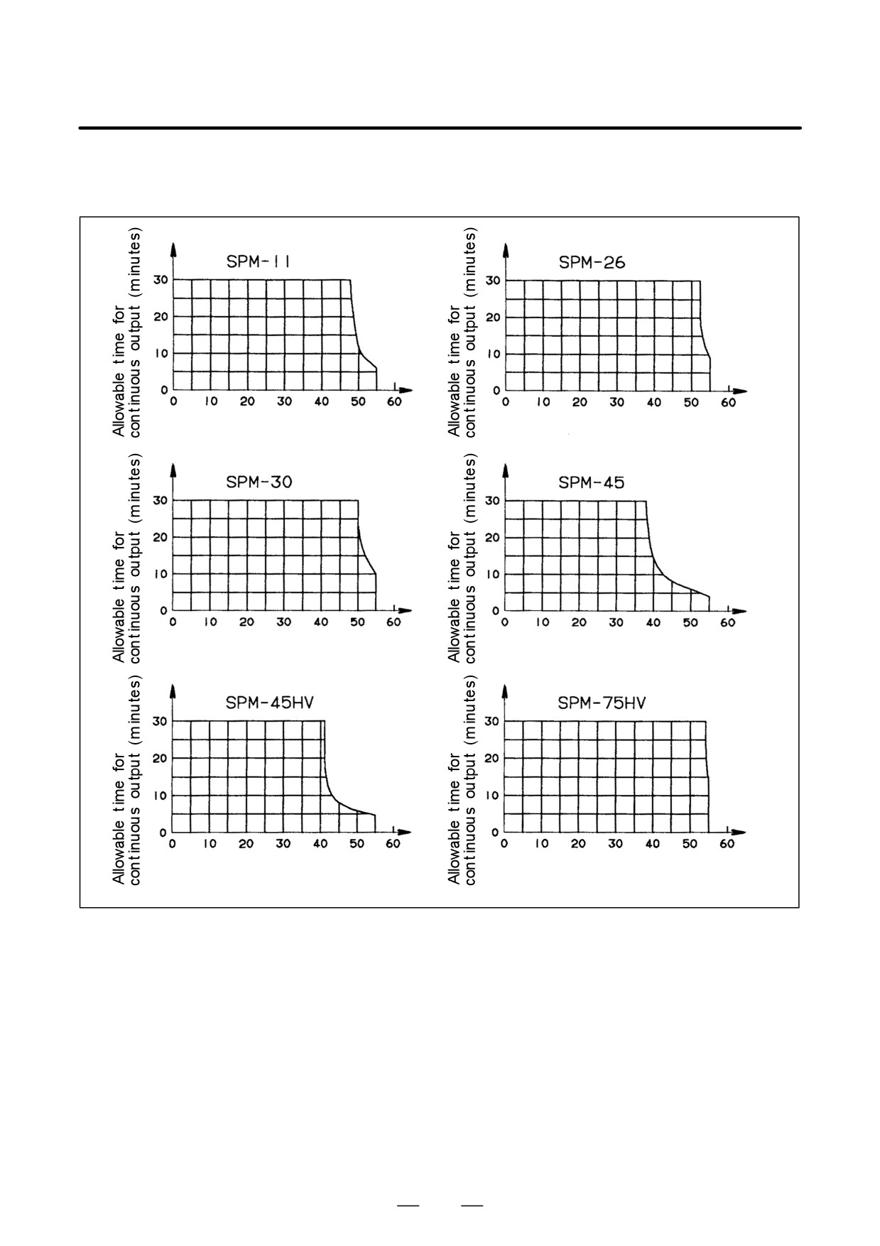
Some amplifier models are certified as conforming to standards, with the
5.4.6
load reduction factors shown below being set.
Decrease in Load
If such an amplifier is used with a load factor exceeded, the allowable
Factor for Given
temperature range of a component may be exceeded, which may cause an
Ambient Temperature
overheat alarm or a decrease in the component life. Therefore, use the
amplifier within the decrease characteristic.
(1) Power supply module time rating decrease with temperature
See Fig. 5.4.6 (a).
(2) Servo amplifier module time rating decrease with temperature
See Fig. 5.4.6 (b).
(3) Spindle amplifier module time rating decrease with temperature
See Fig. 5.4.6 (c).
ÃÃ
ÃÃ
ÃÃ
ÃÃ
ÃÃ
ÃÃ
ÃÃ
ÃÃÃÃÃÃÃÃÃÃÃÃ
Ambient temperature (_C)
Fig.5.4.6 (a) Decreasing Curve of Power Supply Module Time
Rating Dependent on Temperature
141
5. INSTALLATION
B-65162E/03
ÃÃ
ÃÃ
ÃÃ
ÃÃ
ÃÃ
ÃÃ
ÃÃ
ÃÃ
ÃÃ
Ambient temperature (_C)
ÃÃ
ÃÃ
ÃÃ
ÃÃ
ÃÃ
ÃÃ
ÃÃ
ÃÃ
ÃÃ
Ambient temperature (_C)
ÃÃÃÃÃÃÃÃÃÃ
ÃÃ
ÃÃ
ÃÃ
ÃÃ
ÃÃ
ÃÃ
ÃÃ
ÃÃ
ÃÃ
Ambient temperature (_C)
Fig.5.4.6 (b) Decreasing Curve of Servo Amplifier Module
Time Rating Dependent on Temperature
(Single-Axis Amplifiers)
142
B-65162E/03
5. INSTALLATION
ÃÃÃ
ÃÃÃ
ÃÃÃ
ÃÃÃ
ÃÃÃ
ÃÃÃ
ÃÃÃ
ÃÃÃ
ÃÃÃ
Ambient temperature (_C)
ÃÃÃ
ÃÃÃ
ÃÃÃ
ÃÃÃ
ÃÃÃ
ÃÃÃ
ÃÃÃ
ÃÃÃ
ÃÃÃ
Ambient temperature (_C)
ÃÃÃÃÃÃÃÃÃÃ
ÃÃ
ÃÃ
ÃÃ
ÃÃ
ÃÃ
ÃÃ
ÃÃ
ÃÃ
ÃÃ
Ambient temperature (_C)
Fig.5.4.6 (c) Decreasing Curve of Servo Amplifier Module
Time Rating Dependent on Temperature
(Two-Axes Amplifiers)
143
5. INSTALLATION
B-65162E/03
(Applied to the L-axis) Ã
ÃÃÃÃÃÃÃÃÃ
ÃÃ
ÃÃ
ÃÃ
ÃÃ
ÃÃ
ÃÃ
ÃÃ
ÃÃ
ÃÃ
Ambient temperature (_C)
(Applied to the M-axis)
ÃÃ
ÃÃ
ÃÃ
ÃÃ
ÃÃ
ÃÃ
ÃÃ
ÃÃ
ÃÃ
ÃÃÃÃÃÃÃÃÃÃ
mbient temperature (_C)
Fig.5.4.6 (d) Decreasing Curve of Servo Amplifier Module
Time Rating Dependent on Temperature
(Three-Axes Amplifiers)
144
B-65162E/03
5. INSTALLATION
The allowable continuous output time for
30-minute rated output
decreases depending on the ambient temperature as follows:
ÃÃ
ÃÃ
ÃÃ
ÃÃ
ÃÃ
ÃÃ
ÃÃ
ÃÃ
ÃÃ
ÃÃ
ÃÃ
ÃÃ
ÃÃ
ÃÃ
ÃÃÃÃÃÃÃÃÃÃÃÃÃ
ÃÃ
ÃÃÃÃÃÃÃÃÃÃ
mbient temperature (_C)
Ambient temperature (_C) Ã
ÃÃ
ÃÃÃ
ÃÃ
ÃÃÃ
ÃÃ
ÃÃÃ
ÃÃ
ÃÃÃ
ÃÃ
ÃÃÃ
ÃÃ
ÃÃÃ
ÃÃ
ÃÃÃ
ÃÃ
ÃÃÃ
ÃÃÃÃÃÃÃÃÃÃÃÃÃ
ÃÃÃ
Ambient temperature (_C)
Ambient temperature (_C)
ÃÃÃÃÃÃÃÃÃÃÃ
ÃÃÃÃÃÃÃÃÃÃ
ÃÃ
ÃÃ
ÃÃ
ÃÃ
ÃÃ
ÃÃ
ÃÃ
ÃÃ
ÃÃ
ÃÃ
ÃÃ
ÃÃ
ÃÃ
ÃÃ
ÃÃ
ÃÃ
Ambient temperature (_C)
Ambient temperature (_C)
Fig.5.4.6 (e) Decreasing Curve of Spindle Amplifier Module Time Rating Dependent on Temperature
145
6. HEAT DISSIPATION
B-65162E/03
HEAT DISSIPATION
6
146
6. HEAT DISSIPATION
B-65162E/03
The heat dissipated by each α series control motor amplifier module is as
6.1
follows:
200-V INPUT SERIES
6.1.1
Power Supply Module
Table.6.1.1 (a) PSM Heat Out Put
Remaining heat in
cabinet
Rated
Total heat
Name
Ordering number
output
dissipation
Forced air
Natural
cooling
ventilation
(Note 1)
PSM-5.5
A06B-6077-H106
5.5kW
100W
53W
(47W)
53W
PSM-11
A06B-6077-H111
11kW
158W
(Note 2)
PSM-15
A06B-6087-H115
15kW
333W
61W
PSM-26
A06B-6087-H126
26kW
597w
75W
PSM-30
A06B-6087-H130
30kW
681W
79W
PSM-37
A06B-6087-H137
37kW
706W
81W
93W
PSM-45
A06B-6081-H106
45kW
921W
(Note 3)
NOTE
1 A vaule enclosed by parentheses indicates the remaining
heat when the module is forcibly air-cooled with an air
flow of 2m/s or more.
2 Requires forced air cooling, equivalent to fan adaptor unit
A06B-6078-K001.
3
Forced air cooling by fan adaptor unit A06B-6078-K003 or
equivalent (2 m/s or more) is required.
Table.6.1.1 (b) PSMR Heat Output
Remaining heat in
cabinet
Rated
Total heat
Name
Ordering number
output
dissipation
Natural
Forced air
ventilation
cooling
PSMR-3
A06B-6081-H103
3.0kW
60W
60W
5.5kW
105W
55W
PSMR-5.5
A06B-6081-H106
7.5kW
130W
60W
147
6. HEAT DISSIPATION
B-65162E/03
Table.6.1.1 (c) AC Reactor
Name
Ordering number
Total heat dissipation
Remarks
7W
When PSM-5.5 is used
For PSM-5.5, 11
A81L-0001-0122
23W
When PSM-11 is used
For PSM-15
A81L-0001-0123
33W
For PSM-26
A81L-0001-0120
42W
For PSM-30
A81L-0001-0124
42W
For PSM-37
A81L-0001-0147
72W
For PSM-45
A81L-0001-0133
67W
Table.6.1.1 (d) AC Line Filter
Name
Ordering number
Total heat dissipation
Remarks
10W
At 2.0kW output
For PSMR-3
A81L-0001-0083#3C
15W
At 3.0kW output
40W
At 5.5kW output
For PSMR-5.5
A81L-0001-0101#C
50W
At 7.5kW output
148
6. HEAT DISSIPATION
B-65162E/03
6.1.2
When a motor other than those listed below is used, its heat output should
be assumed to be that of a listed motor with a higher rated current.
Servo Amplifier
Module
Table.6.1.2 (a) SVM1 (1-AXIS)
Motor used
Remaining heat in cabinet
Ordering
Total heat
Name
Forced air
number
dissipation
Natural
L axis
M axis
N axis
cooling
ventilation
(Note 1)
A06B-6079-H101
SVM1-12
α2/3000
31W
-
-
A06B-6096-H101
A06B-6079-H102
SVM1-20
αC6/2000
34W
-
-
A06B-6096-H102
A06B-6079-H103
SVM1-40S
α6/2000
47W
32W
(30W)
A06B-6096-H103
A06B-6079-H104
SVM1-40L
α22/1500
80W
45W
(41W)
A06B-6096-H104
α6/3000
70W
39W
(36W)
A06B-6079-H105
SVM1-80
α12/3000
91W
47W
(42W)
A06B-6096-H105
α22/2000
106W
54W
(47W)
A06B-6079-H106
α40/2000
144W
66W
(56W)
A06B-6096-H106
α30/3000
167W
-
62W (Note 2)
SVM1-130
A06B-6079-H106
A06B-6096-H106
α40/2000
198W
-
72W (Note 2)
+
(with a fan)
A06B–6078–K002
αL50/2000
229W
-
81W (Note 2)
A06B-6079-H107
SVM1-240
α6/3000
553W
134W
(56W)
A06B-6096-H107
α100/2000
643W
152W
(56W)
A06B-6079-H108
SVM1-360
A06B-6096-
H108
α150/2000
643W
152W
(60W)
NOTE
1 A vaule enclosed by parentheses indicates the remaining heat when the module is forcibly
air-cooled with an air flow of 2m/s or more.
2 Requires forced air cooling equivalent to fan adaptor unit A06B-6078-K002.
149
6. HEAT DISSIPATION
B-65162E/03
Table.6.1.2 (b) SVM2 (2-AXES)
Motor used
Remaining heat in cabinet
Ordering
Total heat
Name
Forced air
number
dissipation
Natural
L axis
M axis
N axis
cooling
ventilation
(Note)
A06B-6079-H201
SVM2-12/12
α2/3000
α2/3000
54W
-
-
A06B-6096-H201
A06B-6079-H202
SVM2-12/20
α2/3000
αC12/2000
68W
-
-
A06B-6096-H202
A06B-6079-H203
SVM2-20/20
αC12/2000
αC12/2000
82W
-
-
A06B-6096-H203
α2/3000
α6/2000
64W
41W
(38W)
A06B-6079-H204
SVM2-12/40
A06B-6096-H204
α2/3000
αC22/1500
97W
54W
(49W)
αC12/2000
α6/2000
77W
45W
(41W)
A06B-6079-H205
SVM2-20/40
A06B-6096-H205
αC12/2000
αC22/1500
111W
60W
(53W)
α6/2000
α6/2000
73W
43W
(39W)
A06B-6079-H206
SVM2-40/40
α6/2000
αC22/1500
107W
57W
(51W)
A06B-6096-H206
αC22/1500
αC22/1500
141W
72W
(63W)
α6/2000
α6/3000
96W
50W
(45W)
α6/2000
α12/3000
118W
59W
(52W)
α6/2000
α22/2000
133W
65W
(57W)
A06B-6079-H207
SVM2-40/80
A06B-6096-H207
αC22/1500
α6/3000
130W
65W
(57W)
αC22/1500
α12/3000
151W
73W
(63W)
αC22/1500
α22/2000
166W
79W
(68W)
α6/3000
α6/3000
119W
58W
(50W)
α6/3000
α12/3000
141W
67W
(57W)
α6/3000
α22/2000
156W
73W
(63W)
A06B-6079-H208
SVM2-80/80
A06B-6096-H208
α12/3000
α12/3000
162W
75W
(64W)
α12/3000
α22/2000
177W
81W
(69W)
α22/2000
α22/2000
192W
87W
(74W)
α6/2000
α22/1500
107W
57W
(51W)
SVM2-40L/
A06B-6079-H209
α12/2000
α22/1500
123W
63W
(56W)
40L
A06B-6096-H209
α22/1500
α22/1500
141W
72W
(63W)
NOTE
A vaule enclosed by parentheses indicates the remaining heat when the module is forcibly
air-cooled with an air flow of 2m/s or more.
150
6. HEAT DISSIPATION
B-65162E/03
Table.6.1.2 (c) SVM3 (3-AXES)
Motor used
Remaining heat in cabinet
Total heat
Ordering
Name
dissipa-
Forced air
number
Natural
L axis
M axis
N axis
tion
cooling
ventilation
(Note)
A06B-6079-H301
SVM3-12/12/12
α2/3000
α2/3000
α2/3000
79W
-
-
A06B-6096-H301
A06B-6079-H302
SVM3-12/12/20
α2/3000
α2/3000
αC12/2000
93W
-
-
A06B-6096-H302
A06B-6079-H303
SVM3-12/20/20
α2/3000
αC12/2000
αC12/2000
106W
-
-
A06B-6096-H303
A06B-6079-H304
SVM3-12/20/20
αC12/2000
αC12/2000
αC12/2000
120W
-
-
A06B-6096-H304
α2/3000
α2/3000
α6/2000
89W
58W
(54W)
A06B-6079-H305
SVM3-20/20/20
A06B-6096-H305
α2/3000
α2/3000
αC22/1500
122W
71W
(65W)
α2/3000
αC12/2000
α6/2000
102W
62W
(57W)
A06B-6079-H306
SVM3-12/20/40
A06B-6096-H306
α2/3000
αC12/2000
αC22/1500
136W
77W
(69W)
αC12/2000
αC12/2000
α6/2000
116W
68W
(62W)
A06B-6079-H307
SVM3-20/20/40
A06B-6096-
H307
αC12/2000
αC12/2000
αC22/1500
150W
82W
(74W)
NOTE
A vaule enclosed by parentheses indicates the remaining heat when the module is forcibly
air-cooled with an air flow of 2m/s or more.
151
6. HEAT DISSIPATION
B-65162E/03
6.1.3
Spindle Amplifier
Module
Table.6.1.3 (a) SPM
Remaining heat in cabinet
Continuous rated
Total heat
Name
Ordering number
output of motor
dissipation
Natural
Forced air cooling
(Note 4)
ventilation
(Note 1)
SPM-2.2
A06B-6078-H202#H500
1.5kW
75W
37W
(32W)
2.2kW
112W
44W
(36W)
SPM-5.5
A06B-6078-H206#H500
3.7kW
120W
46W
(36W)
5.5kW
171W
41W (Note 2)
SPM-11
A06B-6078-H211#H500
7.5kW
218W
46W (Note 2)
SPM-15
A06B-6088-H215#H500
11kW
273W
45W
15kW
435W
53W
SPM-22
A06B-6088-H222#H500
18.5kW
515W
57W
SPM-26
A06B-6088-H226#H500
22kW
684W
62W
SPM-30
A06B-6088-H230#H500
26kW
739W
65W
30kW
911W
75W (Note 3)
SPM-45
A06B-6088-H245#H500
37kW
1123W
85W (Note 3)
NOTE
1 A vaule enclosed by parentheses indicates the remaining heat when the module is forcibly
air-cooled with an air flow of 2m/s or more.
2 Requires forced air cooling equivalent to fan adaptor unit A06B-6078-K001 (with air flow of
2 m/s or greater).
3
Forced air cooling by fan adaptor unit A06B-6078-K003 or equivalent (2 m/s or more) is
required.
4
The rated output is the continuous rated output of the motor.
152