FANUC SERVO AMPLIFIER a series. DESCRIPTIONS (B-65162E/03) - page 4
B-65162E/03
4. SPECIFICATIONS
[How to calculate the power equipment capacity]
Calculate the power equipment capacity using the formula below.
Rated capacity calculated in Section 3.3 or 3.4 (kW)
Power supply
=
capacity (kVA)
Rated capacity of power supply module (kW)
Power supply capacity of power supply
× module having rated output (kVA)
(See Table 4.1.1 (a), (b))
NOTE
Select a power supply for which, when the motor is
accelerated, the input voltage variation does not exceed 7%
(see Subsection 5.2.1 for details).
[How to calculate the input current of the PSM (PSMR)]
Calculate the input current of the PSM (PSMR) by using the formula
below. Refer to the result when selecting the MCC, power cable, and
circuit breaker 1, to be connected to the PSM input section.
Power equipment capacity (kVA)
PSM input
=
ȯ
× 1.2 (margin)
current (Arms)
Ǹ3 Nominal supply voltage (Vrms)
NOTE
Normally, assume the nominal supply voltage (Vrms) to be
200Vrms.
93
4. SPECIFICATIONS
B-65162E/03
4.1.2
Servo Amplifier Module
Table.4.1.2 (a) Specifications (common)
(SVM)
Item
Specifications
Sine-wave PWM control with transistor (IGBT)
Main circuit control method
bridge
Table.4.1.2 (b) Specifications (individual) (1/2)
Servo amplifier module
Applicable
Rated output
Nominal
motor
current
current limit
Connec-
Model name
model
[Arms]
[Ap]
tion axis
SVM1-12
SVM2-12/12
L, M
α1/3000
SVM2-12/20
L
α2/2000
SVM2-12/40
L
α2/3000
SVM3-12/12/12
L, M, N
3.0
12
β0.5/3000
SVM3-12/12/20
L, M
β1/3000
SVM3-12/20/20
L
β2/3000
SVM3-12/12/40
L, M
SVM3-12/20/40
L
SVM1-20
SVM2-12/20
M
αM2/3000
SVM2-20/20
L, M
αM2.5/3000
SVM2-20/40
L
αC3/2000
SVM3-12/12/20
N
αC6/2000
5.9
20
SVM3-12/20/20
M, N
αC12/2000
SVM3-20/20/20
L, M, N
β3/3000
SVM3-12/20/40
M
β6/2000
SVM3-20/20/40
L, M
α3/3000
SVM1-40S
5.9
40
α6/2000
SVM2-12/40
M
SVM2-20/40
M
α3/3000
SVM2-40/40
L, M
α6/2000
12.5
40
SVM3-12/12/40
N
α12/2000
SVM3-12/20/40
N
αC22/1500
SVM3-20/20/40
N
SVM1-40L
α3/3000
SVM2-40/80
L
α6/2000
SVM2-40L/40L
L, M
α12/2000
12.5
40
α22/1500
αC22/1500
94
B-65162E/03
4. SPECIFICATIONS
Table.4.1.2 (b) Specifications (individual) (continued) (2/2)
Servo amplifier module
Rated output
Nominal
Applicable
Con-
current
current limit
motor model
Model name
nection
[Arms]
[Ap]
axis
SVM1-80
α6/3000
SVM2-40/80
M
α12/3000
SVM2-80/80
L, M
α22/2000
α30/1200
18.7
80
αM6/3000
αM9/3000
αL6/3000
αL9/3000
α30/2000
α40/2000
27.9
αM22/3000
αM30/3000
α22/3000
SVM1-130
α30/3000
130
α40/2000
(with FAN)
52.2
αL25/3000
αL50/2000
αM40/3000
(Note 3)
α65/2000
SVM1-240
αM40/3000
98.0
240
(Note 3)
SVM1-240
α300/1200
98.0
240
(2 units used)
α400/1200
α100/2000
α150/2000
SVM1-360
115.0
360
αM40/3000
(Note 3)
NOTE
1 The current limit (peak value) is a standard value. It varies
by about ±10%, depending on the circuit constants.
2 The SVM1-130 requires forced air cooling when driving the
α22/3000, α30/3000, α40/2000 (with a fan), αL25/3000, or
αL50/2000 or αM40/3000. In this case, the rated output
current is 52.2Arms. See 2.2.3 (7) and section 7.
3
αM40/3000 can be driven by several servo amplifier
models. For selection, refer to ”FANUC AC Servo Motor α
Series” (B-65142E).
95
4. SPECIFICATIONS
B-65162E/03
4.1.3
Spindle Amplifier
Module
Table.4.1.3 (a) Spindle amplifier module
Model
SPM-11
SPM-45
SPM-2.2
SPM-5.5
SPM-15
SPM-22
SPM-26
SPM-30
Item
(Note)
(Note)
Rated output
13A
27A
48A
63A
95A
111A
133A
198A
Main circuit control method
Sine-wave PWM control with transistor (IGBT) bridge
Feedback method
Velocity feedback with pulse generator
Speed control range
Speed ratio 1:100
Speed variation rate
0.1% or less of maximum speed (load variation: 10% to 100%)
α15
α6
α12
α22
Applicable motors
α0.5
α1.5 to
α18
α30
α8
αP15
αP40
αP60
(typical examples)
α1
α3
αP22
α40
αP12
αP18
αP50
αP30
NOTE
The SPM-11 or SPM-45 requires forced air cooling (See 2.2.3 (7) and sec. 7.1).
Table.4.1.3 (b) αC Series Spindle Amplifier Modules (SPMC)
Model
SPMC-11
SPMC-2.2
SPMC-5.5
SPMC-15
SPMC-22
SPMC-26
Item
(Note)
Rated output
13A
27A
48A
63A
95A
111A
Main circuit control method
Sine-wave PWM control with transistor (IGBT) bridge
Speed control range
Speed ratio 1:50
Speed variation rate
1% or less of maximum speed (load variation: 10% to 100%)
αC1.5
Applicable motors
αC6
αC15
αC1
αC2
αC12
αC22
(typical examples)
αC8
αC18
αC3
NOTE
When SPMC-11 is used, forced air cooling from the outside is required. See Chapter 7.
96
B-65162E/03
4. SPECIFICATIONS
4.2
400-V INPUT SERIES
4.2.1
Power Supply Module
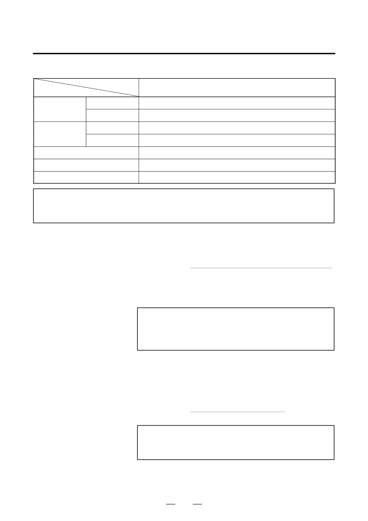
Table.4.2.1 (a) Power Supply Module (PSM-HV)
Model
PSM-75HV
PSM-18HV
PSM-30HV
PSM-45HV
Item
(Note1)
Main circuit
AC400V/460V +10%, -15%, 3φ 50/60Hz,"1Hz
Power supply
(Note 2)
Control power
AC200V/220V/230V +10%, -15%, 1φ 50/60Hz,"1Hz
Main circuit
26kVA
44kVA
64kVA
107kVA
Power equipment
capacity
Control power
0.7kVA
Rated output capacity
18kW
30kW
45kW
75kW
Maximum output capacity
35kW
60kW
85kW
120kW
Control method
Regenerative control (power supply regeneration)
NOTE
1
When the PSM-75HV is being used, forced air cooling from the outside is required. See (7)
in Section 2.2.3 and Chapter 7.
2
If the power supply voltage is beyond the indicated range, a power transformer is required.
3
The PSM-HV models always require a capacitor module (PSMC-HV) listed below.
Table.4.2.1 (b) Capacitor Modules (PSMC-HV)
Model
PSMC-18HV
PSMC-30HV
PSMC-45HV
Item
Rated voltage
AC566V/650V +10%,-15%
PSM-45HV
Applicable PSM
PSM-18HV
PSM-30HV
PSM-75HV
97
4. SPECIFICATIONS
B-65162E/03
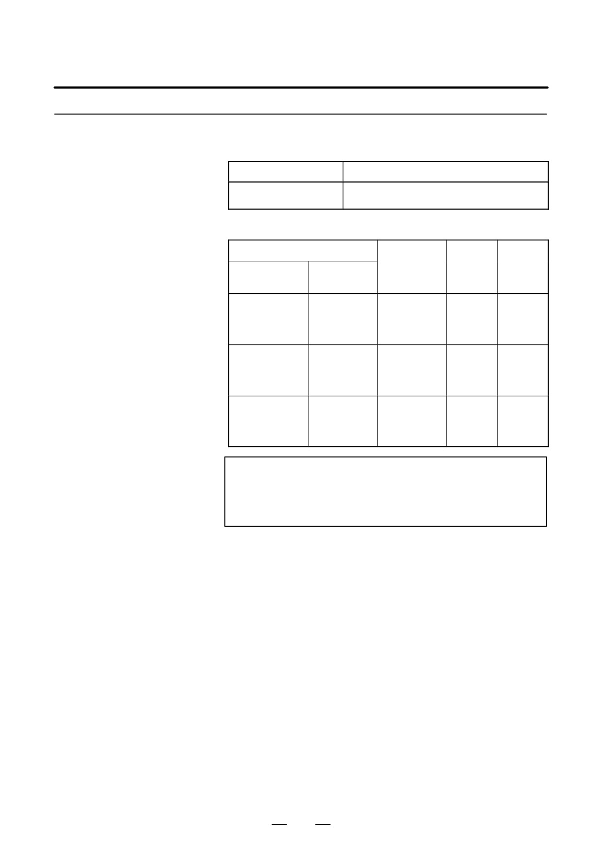
Table.4.2.1 (c) Power Supply Module (PSMV-HV)
Model
PSMV-11HV (Note 2)
Item
Main circuit
AC400V/460V +10%,-15%, 3φ 50/60Hz, "1Hz
Power supply
(Note 1)
Control power
AC200V/220V/230V +10%, -15%, 1φ 50/60Hz, "1Hz
Main circuit
31kVA
Power equipment
capacity
Control power
0.7kVA
Rated output capacity
11kW
Maximum output capacity
20kW
Control method
Regenerative control (power supply regeneration)
NOTE
1
If the power supply voltage is beyond the indicated range, a power transformer is required.
2
PSMV-HV always requires an AC reactor unit.
[How to calculate the power equipment capacity]
Calculate the power equipment capacity using the formula below.
Rated capacity calculated in Section 3.5 or 3.6 (kW)
Power supply
=
capacity (kVA)
Rated capacity of power supply module (kW)
Power supply capacity of power supply
× module having rated output (kVA)
(See Table 4.2.1 (a), (c))
NOTE
Select a power supply for which, when the motor is
accelerated, the input voltage variation does not exceed 7%
(see Subsection 5.2.1 for details).
[How to calculate the input current of the PSM (PSMR) - HV]
Calculate the input current of a PSM(PSMV)HV from the expression
below. Based on the obtained input current value, select the equipment
to be installed in the PSM input section, such as circuit breaker 1, MCC,
and power cable. (Margin for selection: 1 to 1.5 times)
Power equipment capacity (kVA)
PSM input
=
ȯ
× 1.2 (margin)
current (Arms)
Ǹ3 Nominal supply voltage (Vrms)
NOTE
Normally, assume the nominal supply voltage (Vrms) to be
400Vrms.
98
B-65162E/03
4. SPECIFICATIONS
4.2.2
Servo Amplifier Module
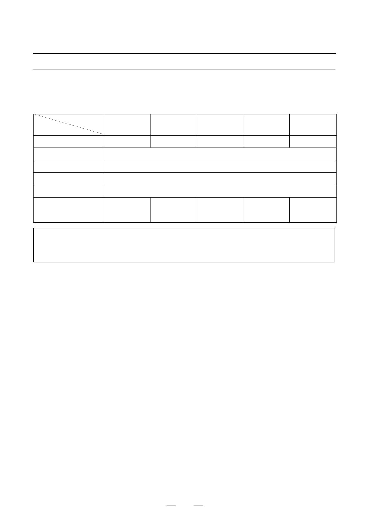
Table.4.2.2 (a) Specifications (common)
(SVM-HV)
Item
Specifications
Sine-wave PWM control with transistor (IGBT)
Main circuit control method
bridge
Table.4.2.2 (b) Specifications (individual)
Servo amplifier module
Rated
Applicable
Nominal
output
motor
current
Connection
current
Model name
model
limit [Ap]
axis
[Arms]
SVM1-20HV
α3/3000HV
3.6
20
SVM2-20/20HV
L-and M-axes
α6/3000HV
SVM2-20/40HV
L-axes
SVM2-20/60HV
L-axes
SVM1-40HV
α12/3000HV
12.6
40
SVM2-20/40HV
M-axes
αM6/3000HV
SVM2-40/40HV
L-and M-axes
αM9/3000HV
SVM2-40/60HV
L-axes
SVM1-60HV
α22/3000HV
16.3
60
SVM2-20/60HV
M-axes
α30/3000HV
SVM2-40/60HV
M-axes
αM22/3000HV
SVM2-60/60HV
L-and M-axes
αM30/3000HV
NOTE
The current limit (peak value) is the standard setting. The
operating value variation due to, for example, a circuit
constant is approximately"10%.
99
4. SPECIFICATIONS
B-65162E/03
4.2.3
Spindle Amplifier
Module
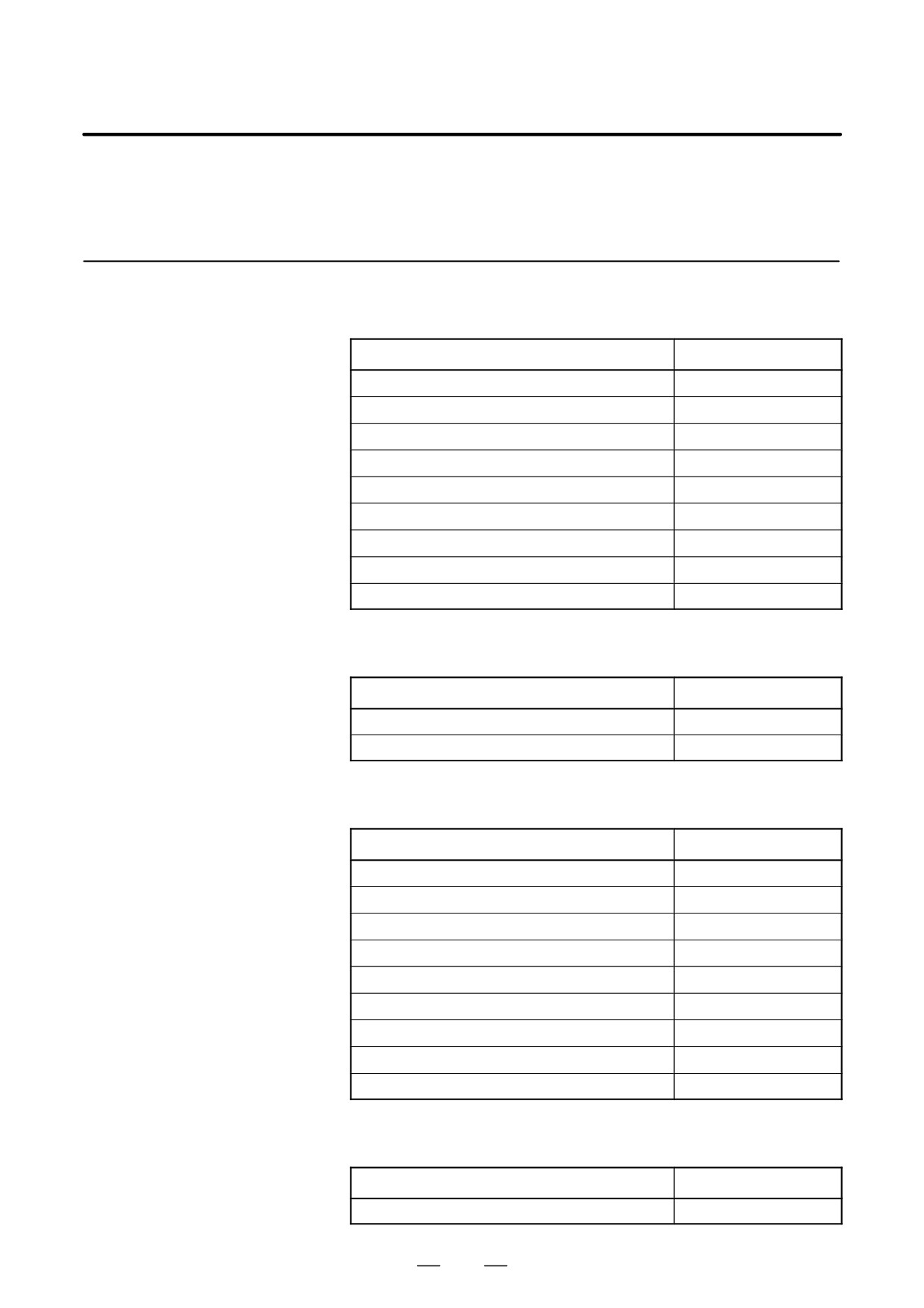
Table.4.2.3 Spindle amplifier module
Model
SPM-11HV
SPM-75HV
SPM-15HV
SPM-26HV
SPM-45HV
Item
(Note)
(Note)
Rated output
23A
32A
55A
100A
170A
Main circuit control method
Sine-wave PWM control with transistor (IGBT) bridge
Feedback method
Velocity feedback with pulse generator
Speed control range
Speed ratio 1:100
Speed variation rate
0.1% or less of maximum speed (load variation: 10% to 100%)
α15HV
α6HV
α30HV
Applicable motors
α12HV
α18HV
α60HV
α8HV
α40HV
α22HV
NOTE
When SPM-11HV or SPM-75HV is used, forced air cooling from the outside is required. See
(7) in Section 2.2.3 and Chapter 7.
100
B-65162E/03
4. SPECIFICATIONS
4.3
WEIGHT
4.3.1
Power Supply Modules
Table.4.3.1 (a) Power Supply Modules
Model
Weight
PSM-5.5
6.3kg
PSM-11
5.4kg
PSM-15,26,30,37
10.7kg
PSM-45
22.0kg
PSMR-3
2.6kg
PSMR-5.5
4.3kg
PSM-18HV,30HV,45HV
11.0kg
PSM-75HV
22.0kg
PSMV-11HV
10.5kg
Table.4.3.1 (b) Capacitor Modules
Model
Weight
PSMC-18HV,30HV
4.0kg
PSMC-45HV
6.5kg
Table.4.3.1 (c) AC Reactors and AC Line Filters
Model
Weight
A81L-0001-0122 (For PSM-5.5, 11)
4.5kg
A81L-0001-0123 (For PSM-15)
6.5kg
A81L-0001-0120 (For PSM-26)
9.5kg
A81L-0001-0124 (For PSM-30)
9.2kg
A81L-0001-0147 (For PSM-37)
16.5kg
A81L-0001-0133 (For PSM-45, 75HV)
38.0kg
A81L-0001-0127 (For PSM-18HV, 30HV, 45HV)
15.0kg
A81L-0001-0083#3C (For PSMR-3)
1.1kg
A81L-0001-0101#C (For PSMR-5.5)
3.0kg
Table.4.3.1 (d) AC Reactor Unit
Model
Weight
A06B-6098-H001 (For PSMV-11HV)
17.0kg
101
4. SPECIFICATIONS
B-65162E/03
4.3.2
Servo Amplifier
Table.4.3.2 Servo Amplifier Modules
Modules
Model
Weight
SVM1-12,20
2.2Kg
SVM1-40S,40L,80
4.8Kg
SVM1-130
6.5Kg
SVM1-240,360
10.7Kg
Dynamic brake module (DBM) for SVM1-240, 360
5.4Kg
SVM2-12/12,12/20,20/20
2.8Kg
SVM2-12/40,20/40,40/40
5.5Kg
SVM2-40/80,80/80,40L/40L
7.0Kg
SVM3-12/12/12,12/12/20,12/20/20,20/20/20
4.1Kg
SVM3-12/12/40,12/20/40,20/20/40
6.5Kg
SVM1-20HV,40HV,60HV
6.0Kg
SVM2-20/20HV,20/40HV
7.5Kg
SVM2-20/60HV,40/40HV,40/60HV,60/60HV
4.3.3
Spindle Amplifier
Table.4.3.3 Spindle Amplifier Modules
Modules
Model
Weight
SPM-2.2 (TYPE1, 2, 4), SPMC-2.2
4.9Kg
SPM-5.5 (TYPE1, 2, 4), SPMC-5.5, 11
6.1Kg
SPM-11 (TYPE1, 2, 4)
5.4Kg
SPM-15, 26, 30 (TYPE1, 2, 3, 4), SPM-11 (TYPE3)
10.7Kg
SPMC-15, 22, 26
SPM-45 (TYPE1, 2, 3, 4)
22Kg
SPM-11HV (TYPE1, 2, 4)
4.6Kg
SPM-15HV, 26HV, 45HV (TYPE1, 2, 4)
11Kg
SPM-75HV (TYPE1, 2, 3, 4)
22Kg
102
B-65162E/03
5. INSTALLATION
INSTALLATION
5
103
5. INSTALLATION
B-65162E/03
The servo amplifier α series must be installed in a sealed type cabinet to
5.1
satisfy the following environmental requirements:
ENVIRONMENTAL
CONDITIONS
(1)
Ambient Temperature
Ambient temperature of the unit : 0 to 55_C (at operation)
-20 to 60_C
(at keeping and transportation)
Ambient temperature of the storage cabinet :
0 to 45_C
(2)
Humidity
Normally 90% RH or below, and condensation-free
(3)
Vibration
In operation : Below 0.5G
(4)
Atmosphere
No corrosive or conductive mists or drops should deposit directly on
the electronic circuits. (Note)
(5)
Notes on Installation
The αseries servo amplifier is designed to be installed in the power
magnetics cabinet, with its heat sink projecting through the back of
the cabinet. This carries away the heat generated by the semi-
conductors, thus preventing heat from building up in the cabinet as
much as possible. Therefore, note the following when installing the
amplifier.
(a) The heat sink must not be subjected to cutting fluid, oil mist, or
cutting chips. Otherwise, the cooling efficiency will be reduced
so that the characteristics of the amplifier cannot be guaranteed.
This may also shorten the life of the semiconductors.
When installing the amplifier in a power magnetics cabinet which
is designed to draw in air, fit an air filter to the air inlet. In
addition, completely seal all cable holes and doors.
NOTE
Install the electronic circuits in an environment of
contamination level 2 as defined in IEC 60664-1. To
achieve contamination level 2 in a severe environment
where machine tools are used, electronic circuits generally
need to be installed in a cabinet complying with IP54.
(b) No dust or cutting fluid must be able to enter through the exhaust
port. The flow of cooling air must not be obstructed.
(c) The amplifier must be installed where it can be easily inspected,
removed, and remounted for maintenance.
(d) Current lines and signal lines must be separated and noise must
be suppressed. See the section 5.3 and the connection manual for
each CNC for details.
104
B-65162E/03
5. INSTALLATION
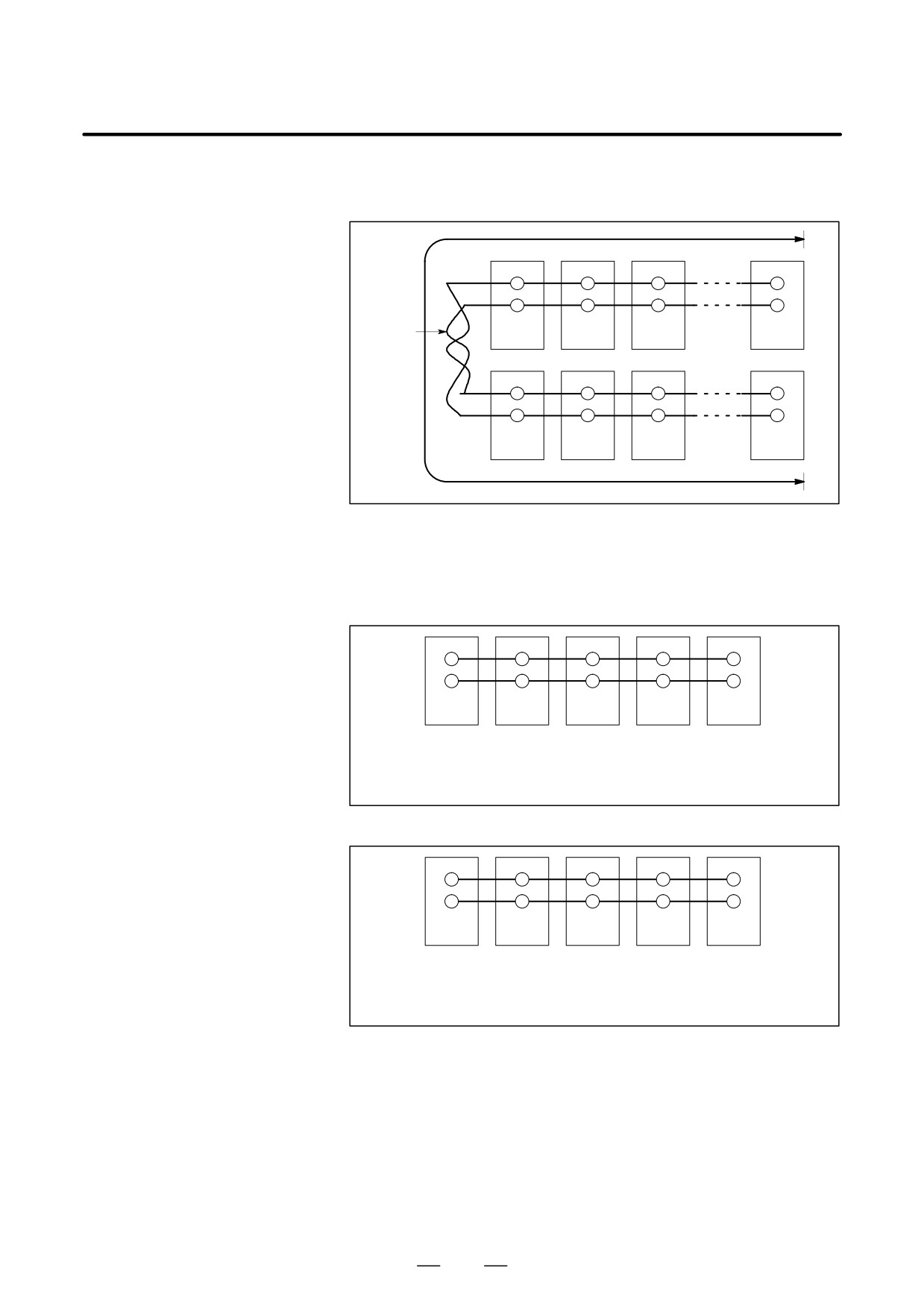
(e) The length of the DC link cable must not exceed 1.5 m (see the
figure below).
Ã
ÃÃ
ÃÃ
ÃÃ
Ã
ÃÃ
ÃÃ
ÃÃ
Twist
PSM
SPM
SVM
SVM
Ã
Ã
Ã
ÃÃ
1.5 m
MAX.
Ã
ÃÃ
ÃÃ
ÃÃ
Ã
ÃÃ
ÃÃ
ÃÃ
SVM
SVM
SVM
SVM
(f) Each amplifier must be installed vertically.
(g) When a PSM-HV is used, the following module layout
restrictions are imposed:
D When PSM-18HV, PSM-30HV, or PSM-45HV is used
Ã
Ã
Ã
Ã
Ã
Ã
Ã
Ã
Ã
ÃÃ
Ã
Ã
Ã
Ã
ÃÃ
PSM
PSMC
SPM
SVM
SVM
Install modules in the order of the PSM, PSMC, SPM, then SVM.
Do not install the modules for apart from each other; install them
side-by-side.
D When the PSM-75HV is used
Ã
Ã
Ã
Ã
ÃÃ
Ã
Ã
Ã
Ã
ÃÃ
PSM
SPM
PSMC
SVM
SVM
Install modules in the order of the PSM, SPM, PSMC, then SVM.
Do not install the modules far apart from each other; install them
in series.
105
5. INSTALLATION
B-65162E/03
5.2
INPUT POWER
AND
GROUNDING
5.2.1
Input Power
(1)
200-V power supply
S Nominal voltage rating
:
200/220/230 VAC
S Allowable voltage deviation
:
-15% to +10% (including Voltage
deviation due to load)
S Power frequency
:
50/60 Hz
S Allowable frequency deviation
:
+1 Hz
S Power supply unbalance
: "5% of the rated voltage or less
S Power supply inpedance
: Voltage deviation due to load
(at maximum output) shall be 5% or
less.
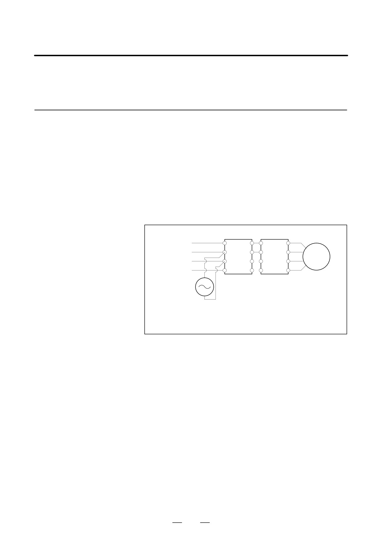
[Method to check power impedance]
R L+
L+
U
AC
Ã
ÃÃÃ
S L-
L- V
power supply
Motor
Ã
ÃÃÃ
Ã
T
W
Ã
ÃÃÃ
Ã
G
G
Ã
ÃÃÃ
Ã
Power supply
Spindle amplifier
AC
module
module or servo
voltmeter
amplifier module
E0-E1
100(%)<7(%)
where,
E0
E0 : Voltage at motor stop
E1 : Voltage during motor acceleration or voltage immediately before the
start of speed reduction with the application of load
D
Turn on the control power supply (CX1A power supply input) of the
power supply module (PSM or PSMR) at the same time or earlier than
the CNC.
D
It is recommended that a capacitor unit for power-factor improvement
not be installed. This is because the capacitor unit for power-factor
improvement may adversely affect power regeneration.
D
The rated output of the motor is guaranteed for the rated input voltage.
If the input voltage changes, the rated output may not appear even
when the input voltage change is within the allowable range.
D
When the power supply is used in an area where the input voltage is
not within the range of 200 to 230 VAC, a power transformer is
required. When a power transformer is to be provided by the user, the
power must satisfy the specifications listed below. For transformers
manufactured by FANUC, see (6) in Section 2.2.3.
106
B-65162E/03
5. INSTALLATION
Table.5.2.1 Transformer Specifications
PSM-5.5
PSM-11
PSMR-3
PSMR-3
PSMR-5.5
PSMR-5.5
PSM-37
(2 kW
(3 kW
PSM-15
PSM-26
PSM-30
(5.5 kW
(7.5 kW
PSM-45
output)
output)
output)
output)
Rated capacity kVA
3.5
5
9
17
22
37
44
64
Secondary current A
10
14
26
48
62
105
130
185
Secondary output voltage
200V
Secondary voltage regulation
5%
Secondary voltage deviation
"3%
107
5. INSTALLATION
B-65162E/03
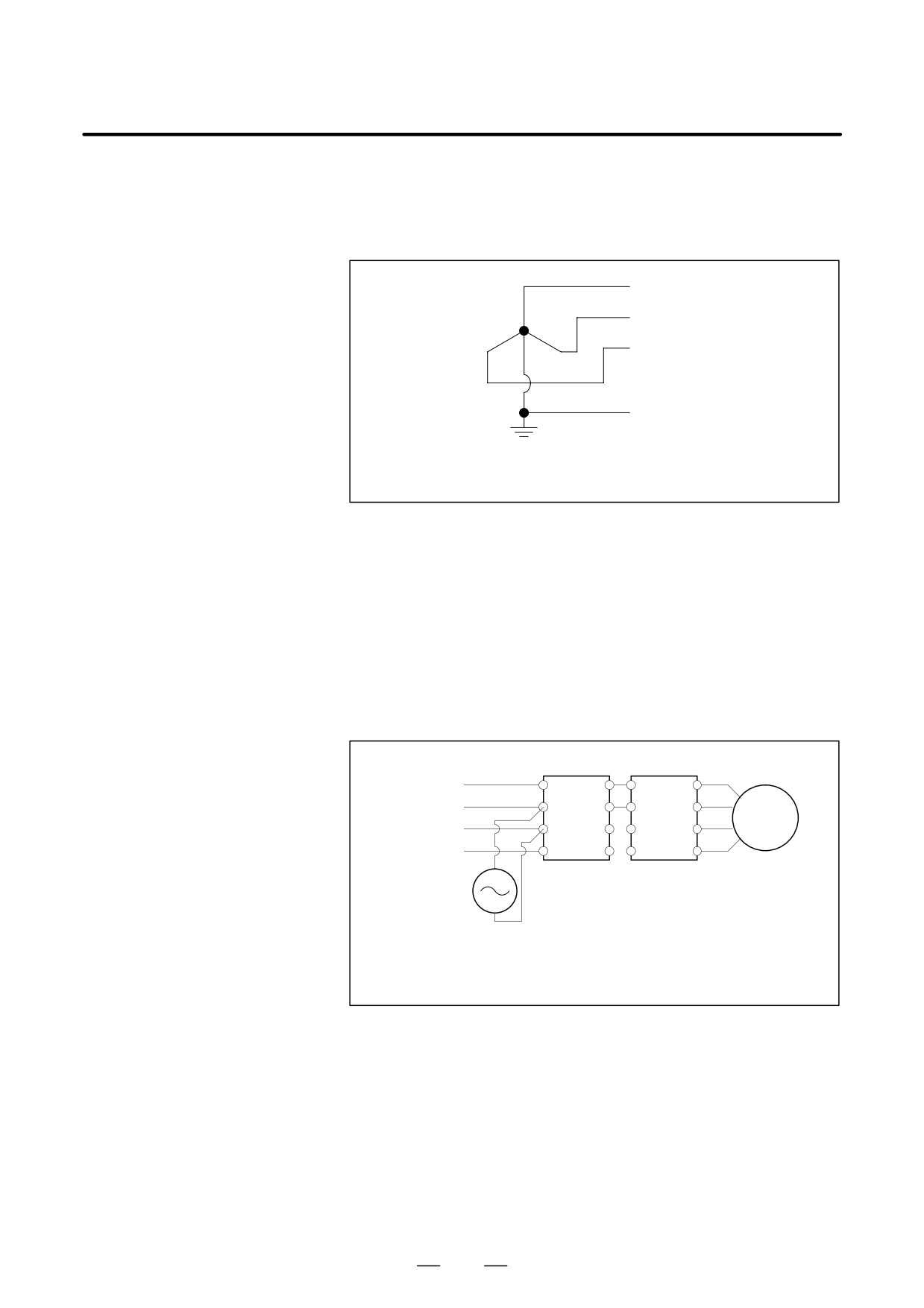
(2)
400-V power supply
S Nominal rated voltage
:
400/460 VAC
Neutral grounding is required.
R
S
T
G
Main circuit input power supply
400/460 VAC
Y-connection (neutral grounding)
S Allowable voltage change width
:
-15% to +10%
(including voltage change
due to the load)
S Power supply frequency
:
50/60 Hz
S Allowable change width
: "1 Hz
S Power supply unbalance
: "5% of the rated voltage or less
S Power supply impedance
: Voltage change due to the load
(at maximum output) is 7%
or less.
[Method to check power impedance]
R Ã
L+
U
Ã
ÃÃ
AC
S L- Ã
L-
V
power supply
Ã
ÃÃ
Motor
T
W
Ã
ÃÃÃ
Ã
G
G
Ã
ÃÃÃ
Ã
Power supply
Spindle amplifier
AC
module
module or servo
voltmeter
amplifier module
E0-E1
100(%)<7(%)
where,
E0
E0 : Voltage at motor stop
E1 : Voltage during motor acceleration or voltage immediately before the
start of speed reduction with the application of load
D
Turn on the control power supply (CX1A power supply input) of a
power supply module (PSM-HV or PSMV-HV) at the same time or
earlier than the CNC.
D
The motor rated output is guaranteed for the rated input voltage. If the
input voltage changes, the rated output may not appear even when the
input voltage change is within the allowable range.
D
It is recommended that a capacitor unit for power-factor improvement
not be installed. This is because the capacitor unit for power-factor
improvement may adversely affect power regeneration.
108
B-65162E/03
5. INSTALLATION
5.2.2
The servo amplifier α series drives the motor by using the transistor
PWM inverter method. This causes a high-frequency leakage current to
Leakage Current
flow via the ground drift capacitance in the motor winding, power cable,
and amplifier. This may cause a device installed on the power supply side,
such as a ground fault interrupter or leakage-protection relay, to
malfunction.
When a circuit breaker with a ground fault interrupter is used, it must be
selected so that the sum of the values calculated according to (a) and (b)
described below is not greater than the non-operating current value.
(a) Selection criterion per amplifier
Model : SVM and SPM (both except the HV series)
(NOTE 1), SPMC
Criterion for selection :
2 mA per amplifier (NOTE 2)
(b) Selection criterion per motor
Criterion for selection :
1 mA per motor (NOTE 2)
The following example shows how to use selection criteria (a) and (b):
Example : When the system consists of SMV1
1,
SVM3
1 (three motors), and SPM
1
2 mA
3 (for the amplifiers) + 1 mA
5 (for the motors)
= 11 mA
→ Select a circuit breaker (NOTE 3) with a non-operating
current of
11 mA or higher.
(A general ground fault
interrupter that can be used for the above example is the one
with a rated sensitivity current of 30 mA and a non-operating
current of 15 mA.)
NOTE
1
In the 400-V input series, the power supply is grounded by
neutral grounding, so there is no leakage current that would
cause a circuit breaker with a ground fault interrupter,
connected on the power supply side, to malfunction.
2
These criteria are for selecting a circuit breaker with a
ground fault interrupter; they do not indicate accurate
leakage currents.
3
A circuit breaker may malfunction depending on the
frequency characteristic of the ground fault interrupter.
Therefore, use a ground fault interrupter supporting the use
of inverters.
4
The above criteria are values in the commercial frequency
band. Some measuring instruments for measuring leakage
current may sense a high frequency band, thus showing a
larger value.
109
5. INSTALLATION
B-65162E/03
5.2.3
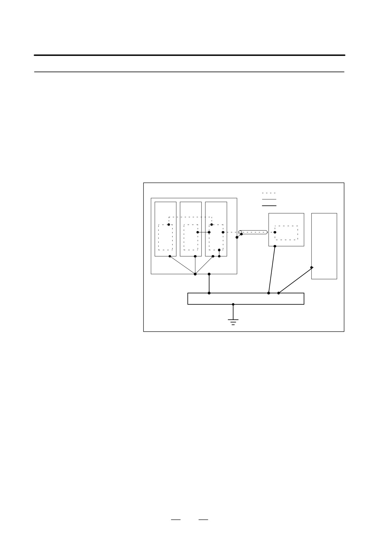
The following ground systems are provided for the CNC machine tool:
D Signal ground system (SG)
Ground
The signal ground (SG) supplies the reference voltage (0 V) of the
electrical signal system.
D Frame ground system (FG)
The frame ground system (FG) is used for safety, and suppressing
external and internal noises. In the frame ground system, the frames,
cases of the units, panels, and shields for the interface cables between
the units are connected.
D System ground system
The system ground system is used to connect the frame ground
systems connected between devices or units with the ground.
Signal ground system
Frame ground sysytem
Power
Servo
CNC
System ground system
magnet-
amplifier
control
ics
unit
Operator’s
unit
panel
Machine
tool
Power
magnetics
cabinet
Distribution board
[Notes on connecting the ground systems]
D Connect the signal ground with the frame ground (FG) at only one
place in the power supply module.
D The grounding resistance of the system ground shall be 100 ohms or
less (class 3 grounding).
D The system ground cable must have enough cross-sectional area to
safely carry the accidental current flow into the system ground when
an accident such as a short circuit occurs.
(Generally, it must have the cross-sectional area of the AC power cable
or more.)
D Use the cable containing the AC power wire and the system ground
wire so that power is supplied with the ground wire connected.
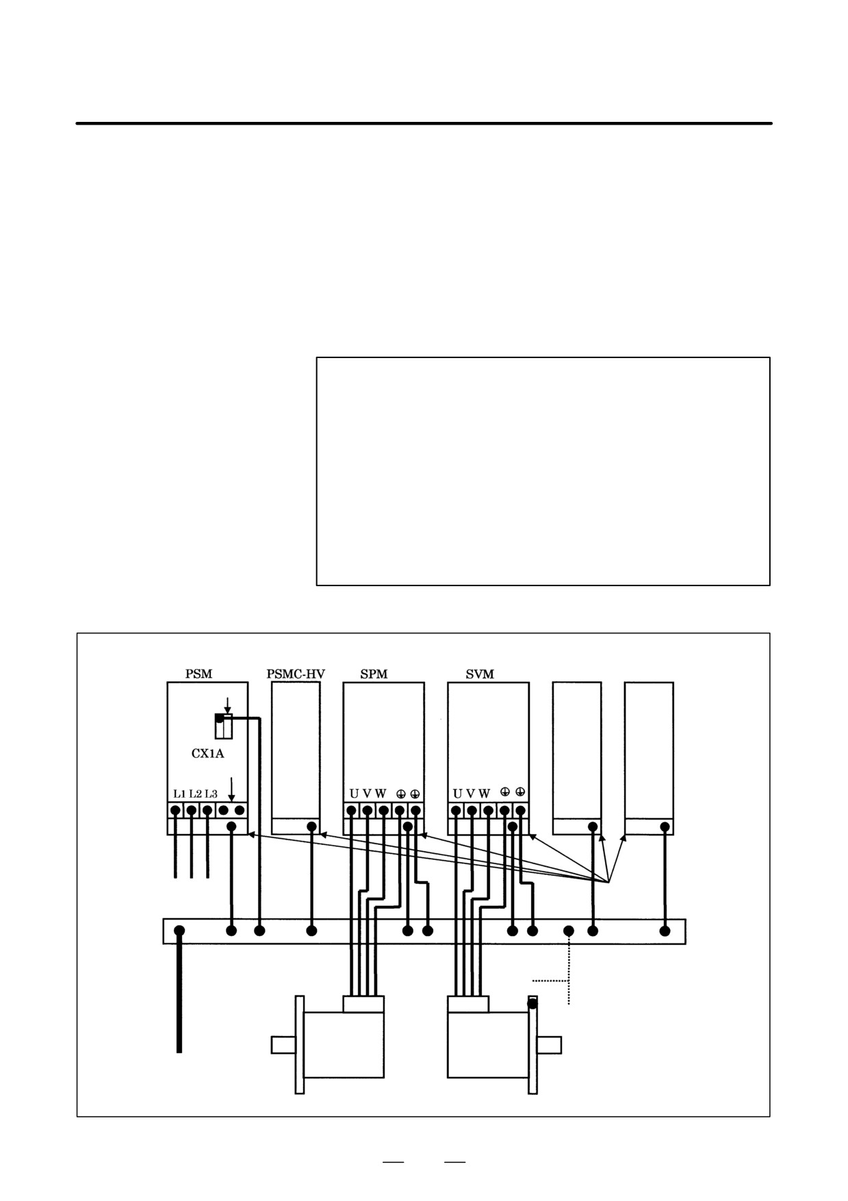
(1) Grounding of each module
(a) Power supply module
Connect the ground terminal of connector CX1A to the frame
ground. This acts as the signal ground. Connect the ground
terminal of the metal frame to the frame ground.
110
B-65162E/03
5. INSTALLATION
(b) Servo amplifier module and spindle amplifier module
Connect the ground cable of the motor power cable to a ground
terminal of the terminal block of the module. Connect the other
ground terminal of the terminal block to the frame ground.
Connect the ground terminal of the metal frame to the frame
ground.
(c) PSMC-HV, regenerative discharge unit, and DBM
Connect the ground terminal of the metal frame to the frame
ground.
NOTE
1
Securing the ground terminal and a cable together is not
permitted.
2
When using an SVM-HV, always attach the motor flange to
the cabinet (machine) connected to the system ground. In
cases where it is difficult to attach the motor flange to the
cabinet
(machine) connected to the system ground,
connect the motor flange and frame ground (the ground
plate of the cabinet) with a 1.25-mm2 or larger cable which
should be separated from the power cable as far as
possible.
(The dotted line in the figure below)
Dynamic brake
Regenerative
module (DBM) discharge unit
Signal ground
Not used
3φ input power supply
Metal
frame
Frame ground
(ground plate of the cabinet)
(Note 2)
Spindle
Servo
motor
motor
System ground
111
5. INSTALLATION
B-65162E/03
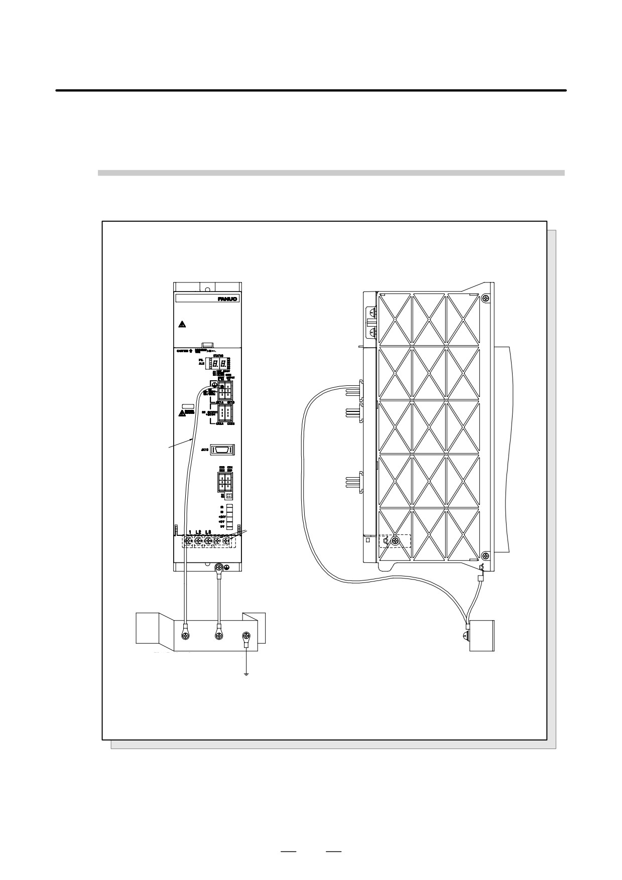
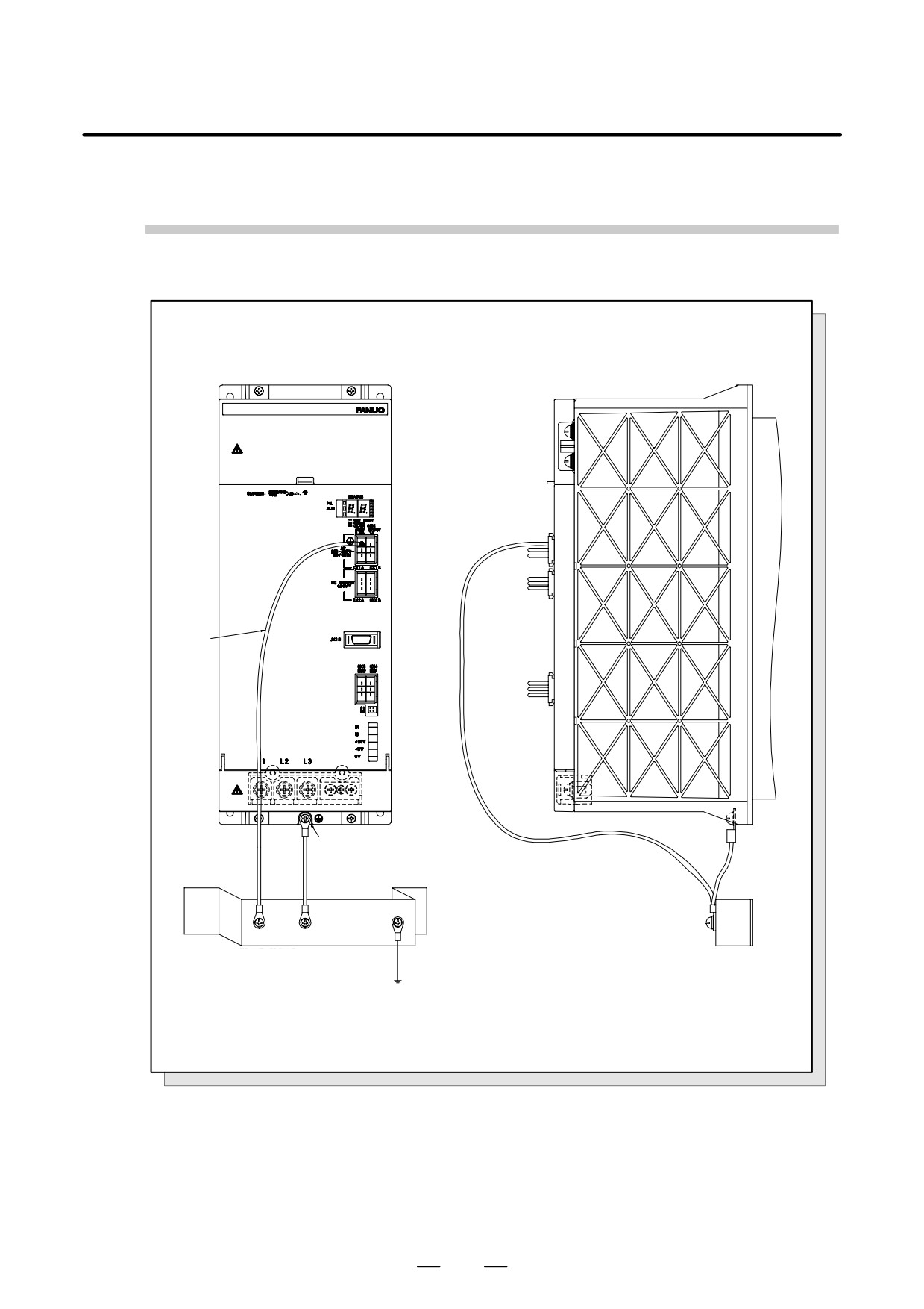
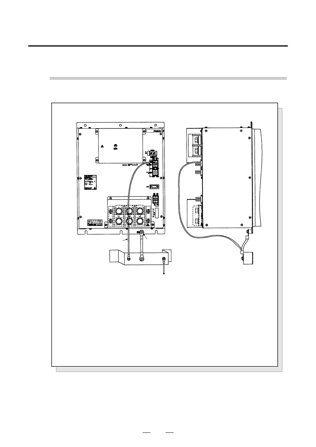
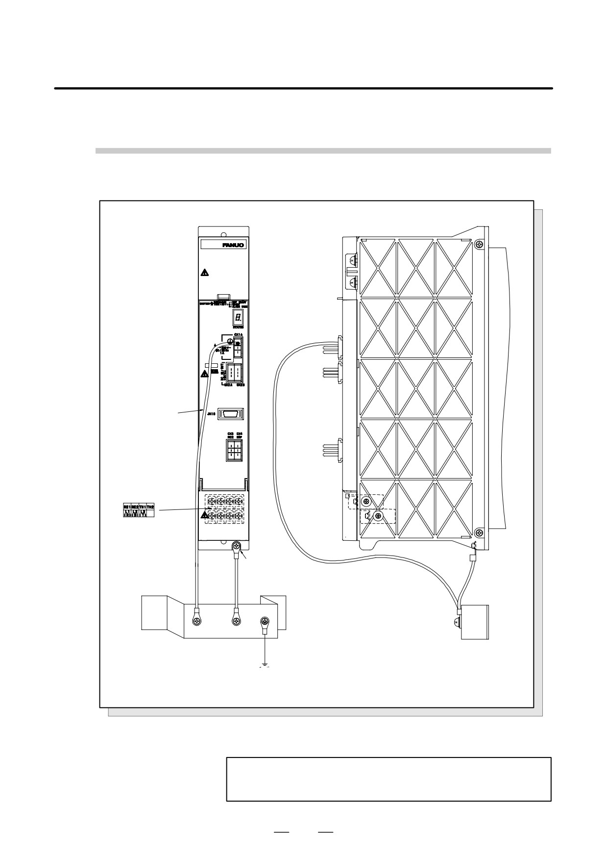
(2) Grounding the power supply module
Detailed examples of grounding the power supply module are given
on the following pages. The cable thickness specifications are as
follows:
(a) Cable between connector CX1A and the frame ground of the
cabinet:
1.25 mm2
(b) Cable between the metal frame of the module and the frame
ground of the cabinet: As indicated in the table below.
Table.5.2.3 (a) Diameter of PSM ground cable (between the metal
frame of the module and the frame ground)
Cross-sectional area of
Cross-sectional area of ground cable
power line
Sx5.5
5.5 or more
5.5<Sx16
S or more
16<Sx35
16 or more
S>35
S/2 or more
(c) Cables connecting the terminal blocks and metal frames of the
servo amplifier and spindle amplifier modules to the cabinet
frame ground.
Determine the cross-sectional area of the cables according to
Table 5.2.3 (b).
Table.5.2.3 (b) Cross-Sectional Areas of SPM and SVM Ground
Cables
Cross-sectional area of power
Cross-sectional area of ground cable
cable S (mm2)
(mm2)
Sx5.5
5.5 or more
5.5<Sx16
S or more
16<Sx35
16 or more
S>35
S/2 or more
(d) Cable connecting the metal frame of the dynamic brake module
(DBM) to the frame ground of the cabinet
Determine the cross-sectional area according to Table 5.2.3 (b).
The cross-sectional area of the power cable in the table matches
the cross-sectional area of the power cable used in the unit to
which the DBM is connected.
NOTE
The following M5 crimp terminal can be used for thick
cables:
CB22-5S manufactured by NICHIFU Co., Ltd.
Applicable cable thickness:
16.78 to 22.66 mm2
112
B-65162E/03
5. INSTALLATION
(3) Examples of grounding
PSM-5.5, PSM-11
ÃGroundÃ
cable
Ã1.25mm2
M5 screw
Cable
Cable
Frame ground (FG)
Frame ground (FG)
Ã
= ground plate of the cabinet
= ground plate of the cabinet
ÃÃÃÃÃÃÃÃm ground
Fig.5.2.3 (a) Ground Cable Connection (PSM-5.5, 11)
113
5. INSTALLATION
B-65162E/03
PSM-15 to 37, 18HV to 45HV, PSMV-11HV
Ground
cable
1.25mm2
M5 screw
Cable
Cable
Frame ground (FG)
Frame ground (FG)
= ground plate of the cabinet
= ground plate of the cabinet
ÃÃÃÃÃÃÃ
System ground
ÃÃÃÃÃÃÃÃÃ
Fig.5.2.3 (b) Ground Cable Connection (PSM-15 to 37, 18HV to 45HV, and PSMV-11HV)
114
B-65162E/03
5. INSTALLATION
Ground Cable Connection (PSM-45, 75HV)
ÃÃÃÃÃ
ÃÃÃÃÃ
round cable
6 screw
1.25mm2
ÃÃÃÃÃ
Frame ground (FG)
ÃFrame ground (FG)ÃÃÃ
= ground plate of the cabinet
= ground plate of the cabinet
System ground Ã
ÃÃÃÃÃÃÃÃÃ
ÃÃÃÃÃÃÃÃÃ
Fig.5.2.3 (c) Ground Cable Connection (PSM-45, 75HV)
115
5. INSTALLATION
B-65162E/03
PSMR-3, PSMR-5.5
Ground
cable
1.25mm2
M4 screw (PSMR-3)
M5 screw (PSMR-5.5)
Cable
Cable
rame ground (FG)
Frame ground (FG)
Ã
= ground plate of the cabinet
= ground plate of the cabinet
System ground
ÃÃÃÃÃÃ
Fig.5.2.3 (d) Ground Cable Connection (PSMR-3, 5.5)
NOTE
For the PSMR-3, the heat sink is not exposed.
116
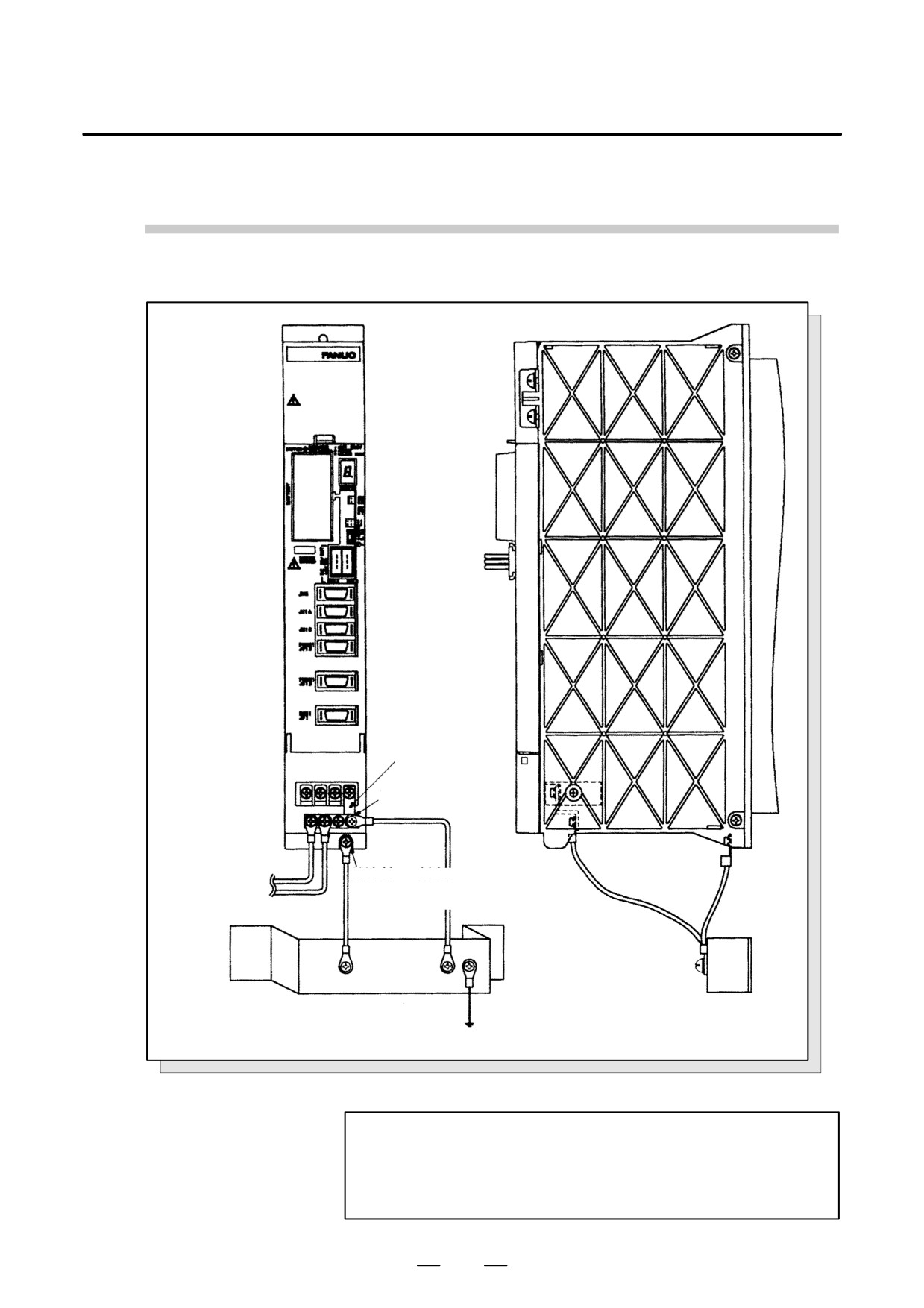
B-65162E/03
5. INSTALLATION
Ground Cable Connection (SVM1-12, 20, 40S, 40L, 80)
Supplied ground Ã
barÃÃÃÃÃ
ÃM4 screw
ÃÃÃÃ
ÃÃÃÃÃ
ÃÃÃÃÃÃ
om motor
M4 screw (with fin)
power cable
M5 screw (with no fin)
(Note 1)
Note 2)
Frame ground (FG)
rame ground (FG)
Ã
cabinet ground plate
cabinet ground plate
System ground
ÃÃÃÃÃ
Fig.5.2.3 (e) Ground Cable Connection (SVM1-12, 20, 40S, 40L, 80)
NOTE
1
A motor has one or two ground cables.
2
Type with no external fin: SVM1-12, 20
Type with external fin: SVM1-40S, 40L, 80
117
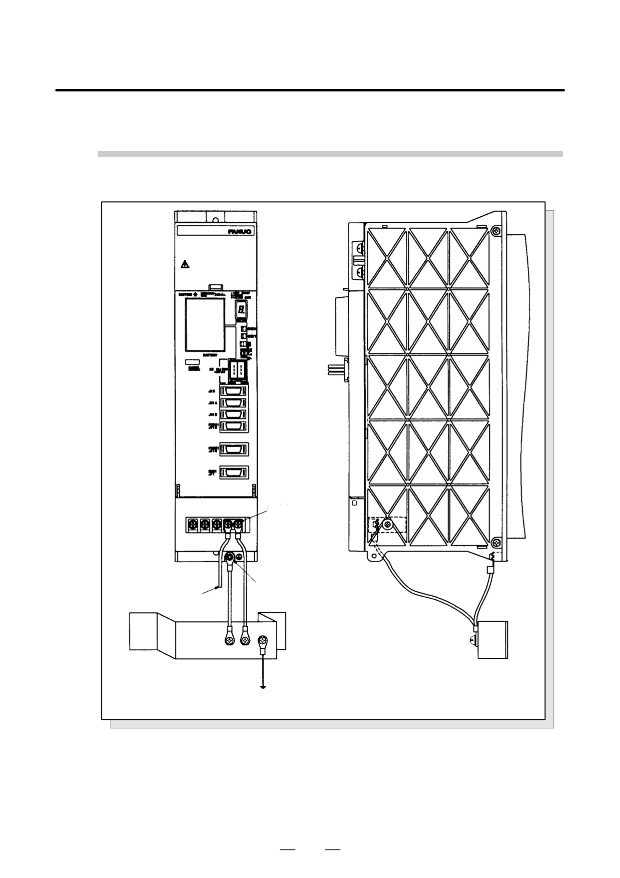
5. INSTALLATION
B-65162E/03
Ground Cable Connection (SVM1-130, 20HV, 40HV, 60HV)
ÃÃÃÃ
4 screw
ÃÃÃÃ
M5 screw
From motor
Ã
power cable
ÃÃÃÃ
ÃÃÃÃÃ
Ã
Frame ground (FG) = cabinet
ÃÃÃÃÃÃÃÃÃÃÃÃÃFrame ground (FG) = cabinet ground plate
ground plate
Ã
ÃÃÃÃÃÃÃÃÃÃÃÃÃ
System ground
Fig.5.2.3 (f) Ground Cable Connection (SVM1-130, 20HV, 40HV, 60HV)
118
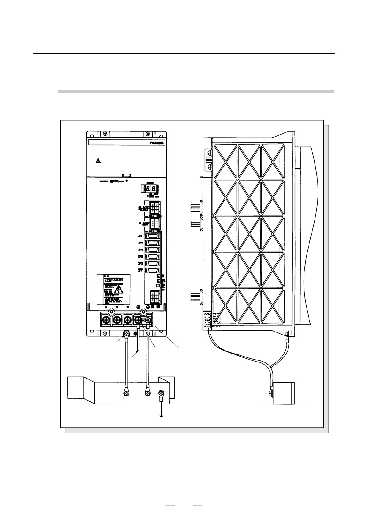
B-65162E/03
5. INSTALLATION
Ground Cable Connection (SVM1-240, 360)
5 screw
Ã
ÃÃÃÃÃÃ
M6
M5 screw
screw Ã
ÃÃÃ
From
motor
ÃÃÃ
power
cable
ÃÃÃÃÃÃÃÃÃÃ
ÃÃÃÃÃÃÃÃÃÃ
Frame ground (FG) = cabinet
Frame ground (FG) = cabinet
ÃÃÃÃÃÃÃÃÃÃ
Ãground plateÃÃÃÃÃÃ
ÃÃÃÃÃÃÃÃÃÃground
ÃÃÃÃÃÃÃÃÃÃ
Fig.5.2.3 (g) Ground Cable Connection (SVM1-240, 360)
119
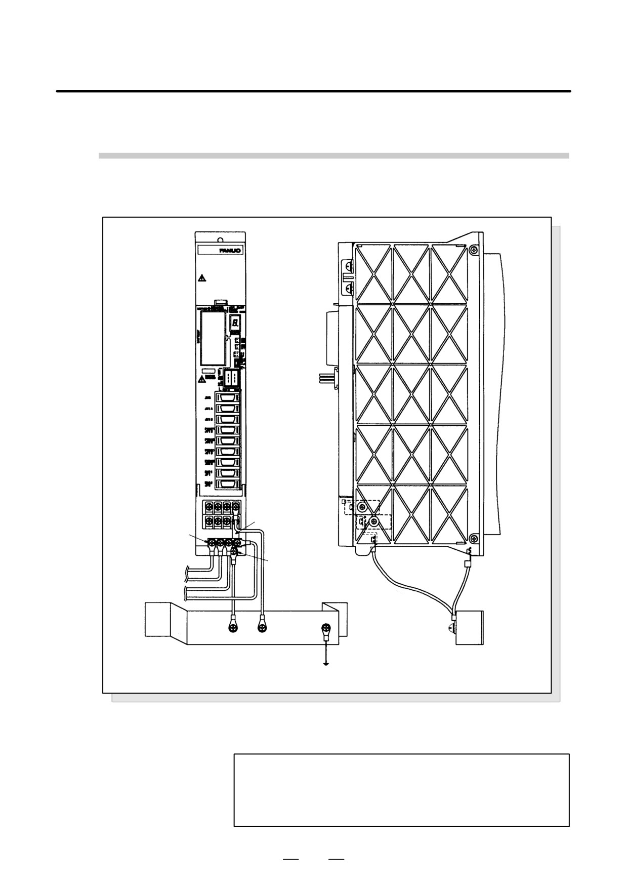
5. INSTALLATION
B-65162E/03
Ground Cable Connection (SVM2-12/12, 12/20, 20/20, 12/40, 20/40, 40/40)
Supplied ground
bar
M4 screw
screw (with no fin)
From L-axis motor
power cable
M5 screw (with ins)
(Note 1)
(Note 2)
From M-axis motor
power cable
(Note 1)
ÃÃÃÃÃÃÃÃÃÃ
Frame ground (FG) = cabinet
ground plate
ground plate
ystem ground
ÃÃÃÃÃÃ
Fig.5.2.3 (h) Servo amplifier module (SVM2-12/12, 12/20, 20/20, 12/40, 20/40, 40/40)
NOTE
1
A motor has one or two ground cables.
2
Type with no external fin: SVM2-12/12, 12/20, 20/20
Type with external fin: SVM2-12/40, 20/40, 40/40
120
B-65162E/03
5. INSTALLATION
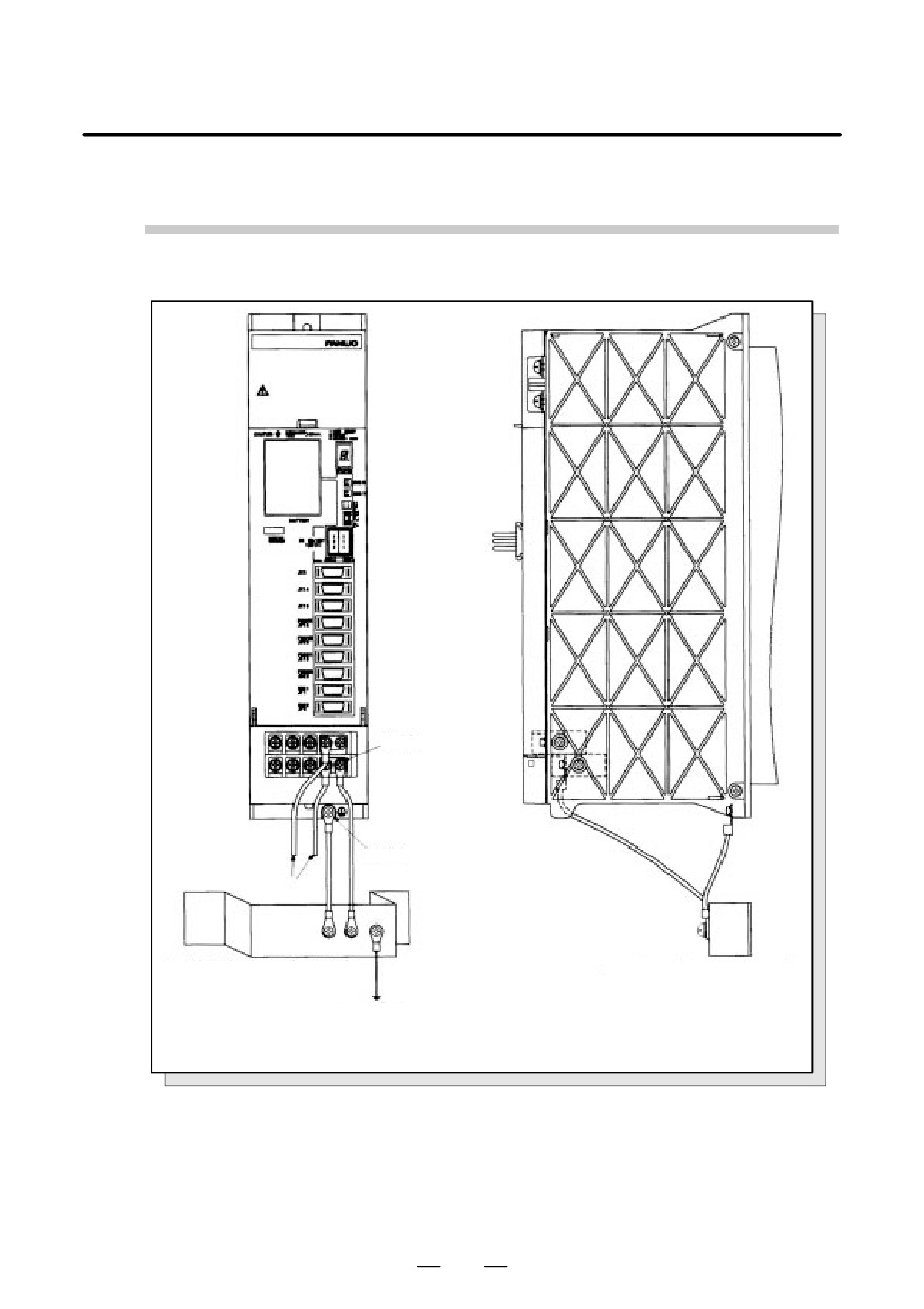
Ground Cable Connection (SVM2-40/80, 80/80, 40L/40L, 20/20HV, 20/40HV,
20/60HV, 40/40HV, 40/60HV, 60/60HV)
4 screw
Ã
M5 screw
ÃÃÃ
From motor power cable
Frame ground (FG) = cabinet
Ã
Frame ground (FG) = cabinet
ground plate
ground plate
Ã
System ground
Fig.5.2.3 (i) Ground Cable Connection (SVM2-40/80, 80/80, 40L/40L, 20/20HV, 20/40HV, 20/60HV,
40/40HV, 40/60HV, 60/60HV)
121
5. INSTALLATION
B-65162E/03
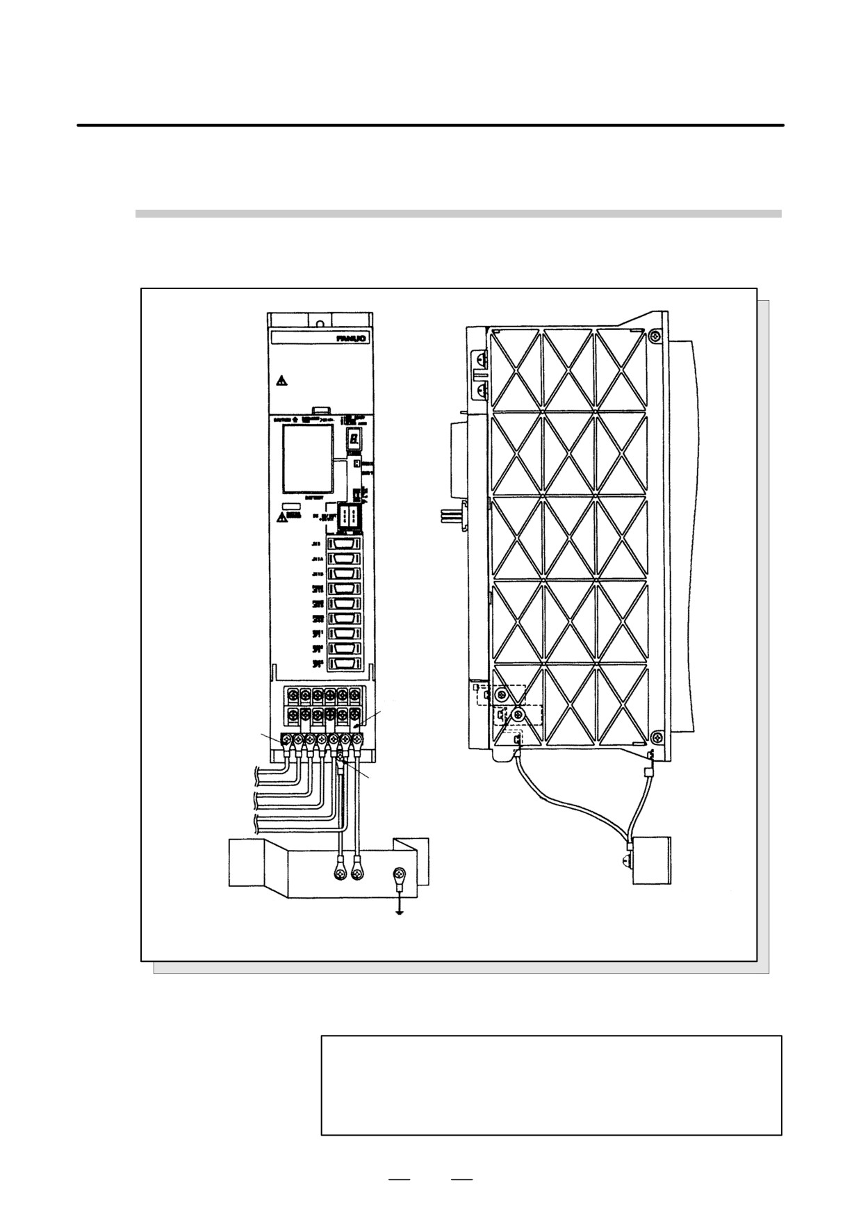
Ground Cable Connection (SVM3)
Ãground barÃ
M4 screw
Ã
ÃÃÃ
ÃÃÃÃÃ
rom L-axis motor
power cable (Note 1)
M5 screw
rom M-axis motor
power cable (Note 2)
From N-axis motor
power cable (Note 1)
ÃÃÃÃÃÃÃÃÃ
Ã
rame ground (FG) = cabinet
Frame ground (FG) = cabinet
round plate
Ãground plateÃÃÃÃS
ystem groundÃ
Ã
ÃÃÃÃÃÃÃÃÃÃÃÃÃ
Fig.5.2.3 (j) Ground Cable Connection (SVM3)
NOTE
1
A motor has one or two ground wires.
2
The heatsink of SVM3-12/12/12, 12/12/20, 12/20/20, and
20/20/20 is not exposed externally.
122