FANUC SERVO AMPLIFIER a series. DESCRIPTIONS (B-65162E/03) - page 3

2. CONFIGURATION AND ORDERING INFORMATION
B-65162E/03
3SUP-AH series and 3SUP-DH series manufactured by Okaya Electric Industries Co., Ltd.
Part number (Okaya Electric Industries)
Rated current
Rated voltage
Remarks
3SUP-A30H-ER-6
30A
AC250V
3SUP-D75H-ER-4
75A
Leakage current:
3SUP-D100H-ER-4
100A
4 mA max
AC500V
at 500VAC, 60 Hz
3SUP-D150H-ER-4
150A
3SUP-D200H-ER-4
200A
For details, refer to the brochures supplied by Okaya Electric Industries Co., Ltd.
NF3000C-TX series manufactured by SOSHIN ELECTRIC CO., LTD.
Part number (SOSHIN ELECTRIC)
Rated current
Rated voltage
Remarks
NF3020C-TX
20A
NF3030C-TX
30A
NF3050C-TX
50A
Leakage current:
250 mA max
NF3080C-TX
80A
AC460V
at 460VAC, 60 Hz
(Note)
NF3100C-TX
100A
NF3150C-TX
150A
NF3200C-TX
200A
For details, refer to the brochures supplied by SOSHIN ELECTRIC CO., LTD.
FN258 series manufactured by SCHAFFNER
Part number (SCHAFFNER)
Rated current
Rated voltage
Remarks
FN258-7
7A
FN258-16
16A
FN258-30
30A
FN258-42
42A
Leakage current:
150 mA max
FN258-55
55A
AC480V
at 250VAC, 50 Hz
(Note)
FN258-75
75A
FN258-100
100A
FN258-130
130A
FN258-180
180A
For details, refer to the brochures supplied by SCHAFFNER.
Agency in Japan: UNIDUX INC.
63
2. CONFIGURATION AND ORDERING INFORMATION
B-65162E/03
NOTE
The NF3000C-TX series manufactured by SOSHIN ELECTRIC CO., LTD. and the FN258
series manufactured by SCHAFFNER have a large line-to-ground capacitor capacitance,
allowing a very high leakage current. Therefore, they can be used only for neutral grounding
type power supplies.
(13) Detectors
α position coder
Category
Name
Ordering number
Remarks
α position coder
A860-0309-T302
j68, 10,000min-1
Optional
Connector kit
A06B-6088-K211
Straight type
High-resolution position coder
Category
Name
Ordering number
Remarks
Optional
High-resolution position coder
A860-0319-T002
j68, 8,000min-1
BZ sensor
Category
Name
Ordering number
Remarks
BZ sensor 128
A860-0392-T012
128 teeth / 20,000min-1
BZ sensor 256
A860-0392-T011
256 teeth / 15,000min-1
BZ sensor 256S
A860-0392-T014
256 teeth / 15,000min-1
Optional
BZ sensor 384
A860-0392-T018
384 teeth / 15,000min-1
BZ sensor 512
A860-0392-T013
512 teeth / 10,000min-1
BZ sensor 128H
A860-0392-T082
128 teeth / 50,000min-1
BZ sensor 256H
A860-0392-T081
256 teeth / 30,000min-1
High-resolution magnetic pulse coder
Category
Name
Ordering number
Remarks
A860-0382-T121
Outside diameter of drum: φ 65
A860-0382-T122
Outside diameter of drum: φ 97.5
High-resolution magnetic
Optional
pulse coder
A860-0382-T123
Outside diameter of drum: φ 130
A860-0382-T124
Outside diameter of drum: φ 195
64
2. CONFIGURATION AND ORDERING INFORMATION
B-65162E/03
Magnetic sensor for orientation
Category
Name
Ordering number
Remarks
Not specified, standard
A57L-0001-0037
Type II, 12,000min-1
Magnetic sensor N
A57L-0001-0037#N
Type II, 12,000min-1
Type II, 12,000min
-1
Magnetic sensor NIP
A57L-0001-0037#NIP
Water-proof connector specification
Magnetic sensor P
A57L-0001-0037#P
Type III, 12,000min-1
Type III, 12,000min
-1
Magnetic sensor PIP
A57L-0001-0037#PIP
Water-proof connector specification
Magnetic sensor Q
A57L-0001-0037#Q
Type IV, 20,000min-1
-1
Type IV, 20,000min
Magnetic sensor QIP
A57L-0001-0037#QIP
Water-proof connector specification
Magnetic sensor R
A57L-0001-0037#R
Type V, 20,000min-1
-1
Type V, 20,000min
Magnetic sensor RIP
A57L-0001-0037#RIP
Water-proof connector specification
-1
Magnetic sensor S
A57L-0001-0037#S
Type VI, 15,000min
Optional
–1
Type VI, 15,000min
Magnetic sensor SIP
A57L-0001-0037#SIP
Water-proof connector specification
Magnetic sensor T
A57L-0001-0037#T
Type VII, 15,000min-1
-1
Type VII, 15,000min
Magnetic sensor TIP
A57L-0001-0037#TIP
Water-proof connector specification
Magnetic sensor U
A57L-0001-0037#U
Type VIII, 20,000min-1
-1
Type VIII, 20,000min
Magnetic sensor UIP
A57L-0001-0037#UIP
Water-proof connector specification
Magnetic sensor U1
A57L-0001-0037#U1
Type IX, 15,000min-1
-1
Type IX, 15,000min
Magnetic sensor U1IP
A57L-0001-0037#U1IP
Water-proof connector specification
Magnetic sensor U2
A57L-0001-0037#U2
Type X, 15,000min-1
-1
Type X, 15,000min
Magnetic sensor U2IP
A57L-0001-0037#U2IP
Water-proof connector specification
65
2. CONFIGURATION AND ORDERING INFORMATION
B-65162E/03
(14) Others
Category
Name
Ordering number
Remarks
Battery
A06B-6073-K001
For SVM (Note)
Battery
A06B-6050-K061
For SVM (Note)
Battery case
A06B-6050-K060
For SVM (Note)
Optional
Cable for battery connection
A06B-6093-K810
For SVM (Note)
Connector for battery connection
A06B-6093-K303
For SVM (Note)
Check pin board
A06B-6071-K290
For SVM
Spindle check board
A06B-6078-H001
For SPM and SPMC
NOTE
These parts are required when the interface with the CNC is type B or FSSB, and
absolute-position detection is performed. The battery for the absolute pulse coder can be
connected using one of following two methods:
Connection method 1: A special lithium battery is installed in the α amplifier.
- Use A06B-6073-K001.
Connection method 2: A battery case (A06B-6050-K060) is used.
- Use A06B-6050-K061 or a commercially available size-D battery.
- A cable (A06B-6093-K810) is required.
66
3. HOW TO SELECT THE POWER SUPPLY MODULE
B-65162E/03
HOW TO SELECT THE POWER SUPPLY MODULE
3
67
3. HOW TO SELECT THE POWER SUPPLY MODULE
B-65162E/03
First, select a servo motor, based on the machine specifications. Then,
3.1
select an appropriate servo amplifier module for the selected servo motor.
HOW TO SELECT THE
For combinations of servo motors and servo amplifier modules, see
SERVO AMPLIFIER
Sections 3.1.1 and 3.1.2.
MODULE
Table.3.1 (a) Specifications
Number of
Input
Interface with
No.
Specification
connected axes
voltage
CNC (Note)
1
A06B-6079-H1jj
1
200V
TYPE A & B
2
A06B-6079-H2jj
2
200V
TYPE A & B
3
A06B-6079-H3jj
3
200V
TYPE A
4
A06B-6080-H3jj
3
200V
TYPE B
5
A06B-6096-H1jj
1
200V
FSSB
6
A06B-6096-H2jj
2
200V
FSSB
7
A06B-6096-H3jj
3
200V
FSSB
8
A06B-6085-H1jj
1
400V
TYPE A & B
9
A06B-6085-H2jj
2
400V
TYPE A & B
10
A06B-6097-H1jj
1
400V
FSSB
11
A06B-6097-H2jj
2
400V
FSSB
NOTE
There are three interfaces with the CNC: Type A, Type B,
and FSSB. Check the interface with the CNC being used,
then select an appropriate servo amplifier module.
68
3. HOW TO SELECT THE POWER SUPPLY MODULE
B-65162E/03
Table.3.1 (b) Names
200-V input series
200-V input series
200-V input series
400-V input series
400-V input series
for 1 axes
for 2 axes
for 3 axes
for 1 axes
for 2 axes
SVM1-12
SVM2-12/12
SVM3-12/12/12
SVM1-20HV
SVM2-20/20HV
SVM1-20
SVM2-12/20
SVM3-12/12/20
SVM1-40HV
SVM2-20/40HV
SVM1-40S
SVM2-20/20
SVM3-12/20/20
SVM1-60HV
SVM2-20/60HV
SVM1-40L
SVM2-12/40
SVM3-20/20/20
SVM2-40/40HV
SVM1-80
SVM2-20/40
SVM3-12/12/40
SVM2-40/60HV
SVM1-130
SVM2-40/40
SVM3-12/20/40
SVM2-60/60HV
SVM1-240
SVM2-40/80
SVM3-20/20/40
SVM1-360
SVM2-80/80
SVM2-40L/40L
Naming convention
SVM j-j / j / j j
(1)
(2)
(3)
(4)
(5)
(6)
(1) Servo amplifier module
(2) Number of axes
1 = 1-axis amplifier, 2 = 2-axis amplifier, 3 = 3-axis amplifier
(3) Maximum current for the L-axis
(4) Maximum current for the M-axis
(5) Maximum current for the N-axis
(6) Input voltage
None = 200 V, HV = 400 V
69
3. HOW TO SELECT THE POWER SUPPLY MODULE
B-65162E/03
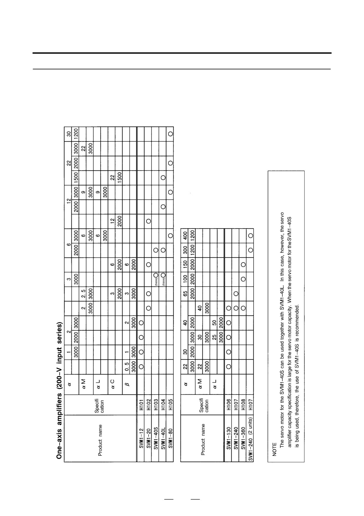
3.1.1
200-V Input Series
(1) One-axis amplifier
70
3. HOW TO SELECT THE POWER SUPPLY MODULE
B-65162E/03
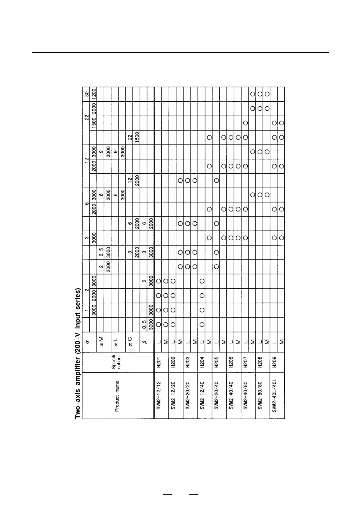
(2) Two-axis amplifier
71
3. HOW TO SELECT THE POWER SUPPLY MODULE
B-65162E/03
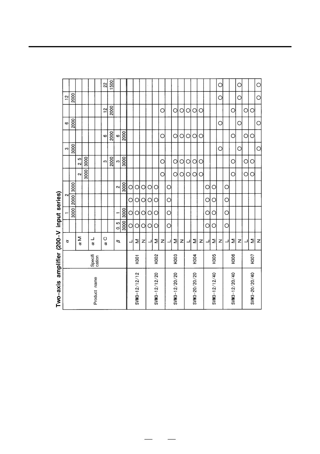
(3) Three-axis amplifier
72
3. HOW TO SELECT THE POWER SUPPLY MODULE
B-65162E/03
3.1.2
400-V Input Series
(1) One-axis and two-axis amplifiers
One-axis amplifier (400-V input series)
3
6
12
22
30
αHV
3000
3000
3000
3000
3000
Specifi-
Product name
cation
6
9
22
30
αM
HV
3000
3000
3000
3000
SVM1-20HV
H102
f
f
SVM1-40HV
H103
f
f
SVM1-60HV
H104
f
f
Two-axis amplifier (400-V input series)
3
6
12
22
30
αHV
3000
3000
3000
3000
3000
Specifi-
Product name
cation
6
9
22
30
αM
HV
3000
3000
3000
3000
L
f
f
SVM2-20/20HV
H201
M
f
f
L
f
f
SVM2-20/40HV
H202
M
f
f
L
f
f
SVM2-20/60HV
H203
M
f
f
L
f
f
SVM2-40/40HV
H204
M
f
f
L
f
f
SVM2-40/60HV
H205
M
f
f
L
f
f
SVM2-60/60HV
H206
M
f
f
73
3. HOW TO SELECT THE POWER SUPPLY MODULE
B-65162E/03
First, select a spindle motor, based on the machine specification. Then,
3.2
select an appropriate spindle amplifier module for the selected spindle
SELECTING A
motor.
SPINDLE AMPLIFIER
Spindle amplifier modules and standard motors that can be used together
MODULE
are shown below. When using a built-in motor or a motor with special
specifications, refer to relevant specifications, and select
a
spindle
amplifier module accordingly.
Table.3.2 (a)
200-V Input Series
Model
Example of motors used
SPM-2.2
α0.5, α1
SPM-5.5
α1.5, α2, α3
SPM-11
α6, α8, αP8, αP12
SPM-15
α12, αP15, αP18
SPM-22
α15, α18, αP22, αP30
SPM-26
α22, αP40, αP50
SPM-30
αP60
SPM-45
α30, α40
SPMC-2.2
αC1
SPMC-5.5
αC1.5, αC2, αC3
SPMC-11
αC6, αC8
SPMC-15
αC12
SPMC-22
αC15, αC18
SPMC-26
αC22
Table.3.2 (b)
400-V Input Series
Model
Example of motors used
SPM-11HV
α6HV, α8HV
SPM-15HV
α12HV
SPM-26HV
α15HV, α18HV, α22HV
SPM-45HV
α30HV, α40HV
SPM-75HV
α60HV
74
3. HOW TO SELECT THE POWER SUPPLY MODULE
B-65162E/03
Select a power supply module that satisfies the rated output capacity and
3.3
maximum output capacity, calculated as follows:
HOW TO SELECT THE
POWER SUPPLY
MODULE (PSM)
3.3.1
Select a power supply module with a rated output not less than the sum
of the total continuous rated output of the spindle motors times 1.15, plus
Rated Output Capacity
the total continuous rated output of the servo motors times 0.6.
Rated output capacity of
Continuous rated output
yΣ
×1.15
power supply module
of spindle motor
Continuous rated output
+Σ
×0.6
of servo motor
When only one spindle amplifier module is to be connected to a power
supply module, select the power supply module so that the 30-minute
rated output of the spindle motor does not exceed the rated output capacity
of the power supply module.
Rated output capacity of a power supply module y 30- minute rated out-
put of a spindle motor
Table 4.1.1 (a) lists the rated output capacities of the power supply
modules. Table 3.7.1 lists the continuous rated outputs of the servo
motors. Table 3.7.2 list the continuous rated outputs of the spindle
motors.
3.3.2
Select a power supply module with a maximum output not less than the
sum of the total accelerating maximum output of the spindle motors and
Maximum Output
the total accelerating maximum output of those servo motors that
Capacity of Power
accelerate/decelerate at the same time.
Supply Module
When the rated output capacity is 11 kW or less, calculate the maximum
output capacity according to 3.3.2-(1), below. When the rated output
capacity is 12 kW or more, calculate according to 3.3.2-(2).
(1) For a rated output capacity of 11 kW or less
Maximum output
Accelerating maximum
yΣ
×1.15
of power supply module
output of spindle motor
Accelerating maximum output of servo motor
×0.6
+Σ
(for simultaneous acceleration/deceleration axis)
When the obtained value at the right-hand side is 20 kW or more,
calculate the maximum output capacity according to 3.3.2-(2).
(2) For a rated output capacity of 12 kW or more
Maximum output
Accelerating maximum
yΣ
of power supply module
output of spindle motor
Accelerating maximum output of servo motor
+Σ
(for simultaneous acceleration/deceleration axis)
75
3. HOW TO SELECT THE POWER SUPPLY MODULE
B-65162E/03
Table 4.1.1 (a) lists the maximum output capacities of the power supply
modules. Table 3.7.1 lists the accelerating maximum outputs of the servo
motors. Table 3.7.2 lists the accelerating maximum outputs of the spindle
motors.
Multiple servo amplifier modules and spindle amplifier modules can be
3.3.3
connected to a single power supply module, provided the above output
Number of Connected
capacity conditions are satisfied.
Servo Amplifier
The table below lists the maximum number of modules which can be
Modules and Spindle
connected.
Amplifier Modules
Maximum number of modules that can be connected
SVM
SPM
SPMC
SVM1
SVM2
SVM3
6
2
4
3
NOTE
1
When different types of servo amplifier modules are
connected, the following condition must be satisfied:
6 y Number of SVM1s×1+
Number of SVM2s×1.5+Number of SVM3s×2
The maximum number of servo amplifier modules that
can be connected is the same when a spindle amplifier
module is not used.
2
When SPM-30 is used, PSM-26 and power supply
modules with a capacity less than or equal to the
capacity of PSM-26 cannot be used.
When using SPM-45, use PSM-45.
3.3.4
When a machine, such as a press, with which a machining cycle is
performed frequently is used, select a PSM so that the total maximum
Selecting a Power
output of those axes that are accelerated/decelerated simultaneously does
Supply Module When
not exceed the value 1.5 times greater than the rated continuous output.
the Machining Cycle
Therefore, the PSM is selected as follows:
Frequency is High
Examples
Motor
PSM+SVM
α300/1200
PSM-37+SVM1-240
2
α400/1200
(PSM-30+SVM1-240)
2
76
3. HOW TO SELECT THE POWER SUPPLY MODULE
B-65162E/03
3.3.5
Example of Selecting a
Power Supply Module
(PSM)
(1)
When two α22/2000 servo motors and one αP50 spindle motor are
used
Servo motor α22/2000
Continuous rated output
:
3.8 kW
Maximum output at acceleration
:
7.5 kW
Spindle motor αP50
Continuous rated output
:
22 kW
Maximum output at acceleration
:
36 kW
Rated output capacity of power supply module y Σ spindle motor
continuous rated output
1.15 + Σ servo motor continuous rated
output
0.6
= 22
1.15 + 3.8
2
0.6
= 29.86 Condition 1
Maximum output capacity of the power supply module y Σ
maximum output of the spindle motor at acceleration + Σ maximum
output of the servo motors at acceleration
(simultaneous
acceleration/deceleration)
= 36 + 7.5
2
= 51.0 Condition 2
According to conditions 1 and 2, PSM-30 is selected as the power
supply module.
(2)
When two α6/3000 servo motors and one α22/2000 servo motor, and
one α3 spindle motor are used
Servo motor α6/3000
Continuous rated output
:
1.4 kW
Maximum output at acceleration
:
6.2 kW
Servo motor α22/2000
Continuous rated output
:
3.8 kW
Maximum output at acceleration
:
7.5 kW
Spindle motor α3
Continuous rated output
:
3.7 kW
Maximum output at acceleration
:
6.6 kW
Rated output capacity of power supply module y Σ spindle motor
continuous rated output
1.15 + Σ servo motor continuous rated
output
0.6
= 3.7
1.15 + (1.4
2 + 3.8)
0.6
= 8.215 Condition 3
Since the rated output capacity of the power supply module is not
higher than 11kW, the maximum output capacity can be obtained
from the following expression:
77
3. HOW TO SELECT THE POWER SUPPLY MODULE
B-65162E/03
Maximum output capacity of the power supply module y Σ
maximum output of the spindle motor at acceleration + Σ maximum
output of the servo motors at acceleration
(simultaneous
acceleration/deceleration)
0.6
= 6.6 + (6.2
2 + 7.5)
0.6
= 18.54 Condition 4
According to conditions 3 and 4, PSM-11 is selected as the power
supply module.
78
3. HOW TO SELECT THE POWER SUPPLY MODULE
B-65162E/03
Select a power supply module that satisfies the rated output capacity and
3.4
maximum output capacity, calculated as follows :
HOW TO SELECT THE
POWER SUPPLY
MODULE (PSMR)
3.4.1
Select a power supply module (PSMR) with a rated output not less than
the sum of the total continuous rated output of the spindle motors times
Rated Output Capacity
1.15, plus the total continuous rated output of the servo motors times 0.6.
(PSMR)
Rated output capacity of
Continuous rated output
yΣ
×1.15
power supply module
of spindle motor
(PSMR)
Continuous rated output
+Σ
×0.6
of servo motor
When only one spindle amplifier module is connected to a power supply
module, the power supply module must be selected so that the 30-minute
rated output of the spindle motor does not exceed the rated output capacity
of the power supply module.
Rated output capacity of a power supply module y 30- minute rated out-
put of a spindle motor
Table 4.1.1 (b) lists the rated output capacities of the power supply
modules (PSMR). Table 3.7.1 lists the continuous rated outputs of the
servo motors. Table 3.7.2 list the continuous rated outputs of the spindle
motors.
3.4.2
Select a power supply module (PSMR) with a maximum output not less
than the sum of the total accelerating maximum output of the spindle
Maximum Output
motors and the total accelerating maximum output of those servo motors
Capacity of Power
that accelerate/decelerate at the same time.
Supply Module (PSMR)
Maximum output
Accelerating maximum
yΣ
of power supply module
output of spindle motor
(PSMR)
Accelerating maximum output of servo motor
+Σ
(for simultaneous acceleration/deceleration axis)
Table 4.1.1 (b) lists the maximum output capacities of the power supply
modules. Table 3.7.1 lists the accelerating maximum outputs of the servo
motors. Table 3.7.2 list the accelerating maximum outputs of the spindle
motors.
3.4.3
Multiple servo amplifier modules and spindle amplifier modules can be
connected to a single power supply module, provided the above output
Number of Connected
capacity conditions are satisfied.
Servo Amplifier
The table below lists the maximum number of modules which can be
Modules and Spindle
connected.
Amplifier Modules
79
3. HOW TO SELECT THE POWER SUPPLY MODULE
B-65162E/03
Maximum number of modules that can be connected
SVM
SPM
SPMC
SVM1
SVM2
SVM3
4
0
1
2
2
1
1
1
2
1
1
1
1
3.4.4
Example of Selecting a
(1)
When two α1/3000 servo motors and one α2 spindle motor are used
Power Supply Module
Servo motor α1/3000
(PSMR)
Continuous rated output
:
0.3 kW
Maximum output at acceleration
:
0.9 kW
Spindle motor α2
Continuous rated output
:
2.2 kW
Maximum output at acceleration
:
4.44 kW
Rated output capacity of a power supply module y Σ spindle motor
continuous rated output
1.15 + Σ servo motor continuous rated
output
0.6
= 2.2
1.15 + 0.3
2
0.6
= 2.89 Condition 1
Maximum output capacity of the power supply module y Σ
maximum output of the spindle motor at acceleration + Σ maximum
output of the servo motors at acceleration
(simultaneous
acceleration/deceleration)
= 4.44 + 0.9
2
= 6.24 Condition 2
According to conditions 1 and 2, PSMR-3 is selected as the power
supply module.
(2)
When two α2/2000 servo motor and one α6/2000 servo motor, and
one α3 spindle motor are used
Servo motor α2/2000
Continuous rated output
:
0.4 kW
Maximum output at acceleration
:
1.1 kW
80
3. HOW TO SELECT THE POWER SUPPLY MODULE
B-65162E/03
Servo motor α6/2000
Continuous rated output
:
1.0 kW
Maximum output at acceleration
:
3.8 kW
Spindle motor α3
Continuous rated output
:
3.7 kW
Maximum output at acceleration
:
6.6 kW
Rated output capacity of power supply module y Σ spindle
motor continuous rated output
1.15 + Σ servo motor continuous
rated output
0.6
= 3.7
1.15 + (0.4
2 + 1.0)
0.6
= 5.335 Condition 3
Maximum output capacity of the power supply module y Σ
maximum output of the spindle motor at acceleration + Σ
maximum output of the servo motors at acceleration
(simultaneous acceleration/deceleration)
= 6.6 + (1.1
2 + 3.8)
= 12.6 Condition 4
According to conditions 3 and 4, PSMR-5.5 is selected as the power
supply module.
In the power supply module (PSMR), the regenerative discharge unit
3.4.5
(regenerative resistor) dissipates the energy generated during deceleration
Selecting a
of a motor (regeneration). The amount of heat generated by the
Regenerative
regenerative discharge unit varies with the motor type, rotation speed,
Discharge Unit
load inertia, and continuous repetition cycle
(duty cycle). Use a
regenerative discharge unit of a suitable capacity for the load and
operation cycle time.
(1) How to Calculate the Required Capacity for the Regenerative
Discharge Unit
Select a regenerative discharge unit having a capacity greater than or equal
to the total rotation energy of all the servo motors and the spindle motor.
How to calculate the rotation energy is described in below.
Capacity of regenerative
yΣ
Rotation energy of motor
discharge unit
See Table 3.4.5 for details of the capacity of the regenerative discharge
unit.
1. Servo motor (for horizontal movement)
Amount of regenerative discharge (power [W]) when rapid traverse
acceleration/deceleration is performed once every F sec
(a) SI unit system
1
W+
(5.48
10-3 @ (Jm ) JL) @ Vm2-5.23
10-2
F
@ ta @ Vm @ TL)[W]
81
3. HOW TO SELECT THE POWER SUPPLY MODULE
B-65162E/03
F
: Frequency of rapid traverse acceleration/deceleration [sec/
number of times]
Note) Unless otherwise specified, rapid traverse acceleration/
deceleration is assumed to be performed about once
every 5 seconds.
Jm : Rotor inertia of the motor [kg⋅m2]
JL : Motor-shaft-converted inertia of the load [kg⋅m2]
Vm : Motor speed at rapid traverse [min-1]
ta
: Rapid traverse acceleration/deceleration time [sec]
TL : Machine frictional torque (motor-converted value) [N⋅m]
(b) CGS unit system
1
W+
(5.37
10-4 @ (Jm ) JL) @ Vm2-5.13
10-3
F
@ ta @ Vm @ TL)[W]
F
: Rapid traverse acceleration/deceleration cycle [s/number of
times]
Note) About once every five seconds unless otherwise
specified
Jm : Rotor inertia of motor [kg⋅cm⋅s2]
JL : Load inertia (value for motor shaft) [kg⋅cm⋅s2]
Vm : Motor rotation speed for rapid traverse [rpm]
ta
: Rapid traverse acceleration/deceleration time [s]
TL : Friction torque of machine (value for motor) [kg⋅cm]
2.
Servo motor (for vertical movement)
The amount of regenerative discharge
(power
[W]) when the
operation duty for downward rapid traverse is D(%)
(a) SI unit system
D
W + 1.047
10-1 @ Th @ Vm
[W]
100
Th : Upward torque that the motor applies at the time of downward
rapid traverse [N⋅m]
Vm : Motor speed at rapid traverse [min-1]
D : Operation duty [%] for downward rapid traverse
D is set to 50% maximum. Usually, D is less than 50%.
(b) CGS unit system
D
W + 1.026
10-2 @ Th @ Vm
[W]
100
Th : Upward torque of motor during lowering by rapid traverse
[kg⋅cm]
Vm : Motor rotation speed for rapid traverse [rpm]
D : Downward operation duty during lowering by rapid traverse
[%]
Note) D is a maximum of 50% and usually less.
3.
Spindle motor
(a) SI unit system
1
W + 5.48
10-3 @ (Jm ) JL) @ N2
[W]
Dt
82
3. HOW TO SELECT THE POWER SUPPLY MODULE
B-65162E/03
Jm : Rotor inertia of the motor [kg⋅m2]
JL : Motor-shaft-converted inertia of the load [kg⋅m2]
N : Motor speed [min-1]
Dt : Duty cycle [sec]
(b) CGS unit system
1
W + 5.37
10-2 @ (Jm ) JL) @ N2
[W]
Dt
Jm : Rotor inertia of motor [kg⋅cm⋅s2]
JL : Load inertia (value for motor shaft) [kg⋅cm⋅s2]
N : Motor rotation speed [rpm]
Dt : Duty cycle [s]
Table.3.4.5 Required capacity for the Regenerative
Discharge unit
Capacity
Regenerative
Wind speed
Remarks
discharge unit
0m/sec
2m/sec
4m/sec
A06B-6081-H050
100W
250W
-
Registance : 16Ω
A06B-6066-H500
200W
400W
600W
Registance : 16Ω
Forced cooling fan
A06B-6066-H713
-
-
800W
motor is included
Registance : 16Ω
Forced cooling fan
A06B-6066-H711
-
-
800W
motor is included
Registance : 8Ω
Forced cooling fan
A06B-6066-H712
-
-
1,200W
motor is included
Registance : 8Ω
NOTE
1
The ”maximum output at acceleration” value is provided
only to aid in the selection of a power supply module; this is
not a guaranteed value.
2
When a spindle motor with a maximum output of 5kW or
more is used, the resistance of the regenerative discharge
unit must be 8Ω. If a regenerative discharge unit with a
resistance of
16Ω is used for a spindle motor with a
maximum output of 5 kW or more , a regeneration excess
alarm (alarm No. 08) may be generated in the PSMR when
the spindle is decelerated.
83

3. HOW TO SELECT THE POWER SUPPLY MODULE
B-65162E/03
For how to select a power supply module (PSMV-HV), see Section 3.3,
3.5
and for the rated output capacity, see Table 4.2.1 (3).
SELECTING A
POWER SUPPLY
MODULE (PSMV-HV)
3.5.1
When two α6/3000 servo motors, one α22/2000 servo motor and one α3
spindle motor are used
Example of Selecting a
α6/3000 servo motor
Power Supply Module
Continuous rated output
:
1.4 kW
(PSMV-HV)
Accelerating maximum output
:
6.2 kW
α22/2000 servo motor
Continuous rated output
:
3.8 kW
Accelerating maximum output
:
7.5 kW
α3 spindle motor
Continuous rated output
:
3.7 kW
Accelerating maximum output
:
6.6 kW
Rated output capacity of power supply module
Continuous rated output
Continuous rated output
yΣ
×1.15+Σ
×0.6
of spindle motor
of servo motor
=3.7
1.15\(1.4×2+3.8)
0.6
= 8.215
(1)
As the rated output capacity of the power supply module is less than 11
kW, the following formula is used for calculating the maximum output ca-
pacity:
Maximum output capacity of power supply module
Accelerating maximum output
Accelerating maximum
yΣ
+Σ of servo motor (for simultaneous
×0.6
output of spindle motor
acceleration/deceleration axis)
= 6.6×(6.2
2+7.5)
0.6
= 18.54
(2)
Based on (1) and (2), the PSM-11HV is selected.
84
3. HOW TO SELECT THE POWER SUPPLY MODULE
B-65162E/03
When selecting a power supply module (PSM-HV), calculate the rated
3.6
output capacity and maximum output capacity as explained below, then
SELECTING A
select an appropriate PSM-HV that satisfies these calculated values.
POWER SUPPLY
MODULE (PSM-HV)
3.6.1
Multiply the total continuous rated output of the spindle motors by a
coefficient (1.15), and also multiply the total continuous rated output of
Obtaining the Rated
the servo motors by a coefficient (0.6). Then, select a power supply
Output Capacity of a
module so that the sum of the multiplication results does not exceed the
Power Supply Module
rated output capacity of the power supply module.
Rated output capacity of
Spindle motor continuous
yΣ
×1.15
power supply module
rated output
Servo motor continuous
+Σ
×0.6
rated output
When only one spindle amplifier module is connected to a power supply
module, the power supply module must be selected so that the 30-minute
rated output of the spindle motor does not exceed the rated output capacity
of the power supply module.
Rated output capacity of a power supply module y 30- minute rated out-
put of a spindle motor
For the rated output capacities of the power supply modules, see Table
4.2.1 (a). For the continuous rated outputs of the servo motors, see Table
3.7.1. For the continuous rated outputs of spindle motors, see Table 3.7.2.
Select a power supply module so that the sum of the total maximum
3.6.2
output of the spindle motors at acceleration and the total maximum output
Obtaining the
of simultaneously accelerated/decelerated servo motors at acceleration
Maximum Output
does not exceed the maximum output capacity of the power supply
Capacity of a Power
module.
Supply Module
Maximum output capacity of
maximum output of spindle
yΣ
power supply module
motors at acceleration
maximum output of servo motors at acceleration
+Σ
(simultaneously accelerated/decelerated axes)
For the maximum output capacities of the power supply modules, see
Table 4.2.1 (a). For the maximum outputs of the servo motors at
acceleration, see Table 3.7.1. For the maximum outputs of the spindle
motors at acceleration, see Table 3.7.2.
85
3. HOW TO SELECT THE POWER SUPPLY MODULE
B-65162E/03
3.6.3
Multiple servo amplifier modules and spindle amplifier modules can be
connected to a single power supply module (PSM-HV) provided the
Number of Connected
capacity of the power supply module is not exceeded.
Servo Amplifier
For the number of units that can be connected, see the following table:
Modules and Spindle
Table.3.6.3 Maximum Number of Modules That Can be
Amplifier Modules
Connected
SVM-HV
SPM–HV
SVM1-HV
SVM2-HV
6
2
4
NOTE
When the two types of servo amplifier module are used
together, the result of the following expression must not
exceed 6:
Total number of connected modules (6) Number of SVM1s
x 1 + number of SVM2s x 1.5
Even when no spindle amplifier module is used, the number
of servo amplifier modules that can be connected remains
unchanged.
3.6.4
Example of Selecting a
(1)
When two α12/3000HV servo motors and one α22HV spindle motor
Power Supply Module
are used
(PSM-HV)
Servo motor α12/3000HV
Continuous rated output
:
2.8 kW
Maximum output at acceleration
:
6.3 kW
Spindle motor α22HV
Continuous rated output
:
22 kW
Maximum output at acceleration
:
31.2 kW
Rated output capacity of power supply module y Σ spindle motor
continuous rated output
1.15 + Σ servo motor continuous rated
output
0.6
= 22
1.15 + 2.8
2
0.6
= 28.66 Condition 1
Maximum output capacity of power supply module y Σ maximum
output of the spindle motor at acceleration + Σ maximum output of
the servo motors at acceleration
(simultaneous acceleration
/deceleration)
= 31.2 + 6.3
2
= 43.8 Condition 2
According to conditions 1 and 2, PSM-30HV is selected as the power
supply module.
86
3. HOW TO SELECT THE POWER SUPPLY MODULE
B-65162E/03
3.7
LIST OF MOTOR
OUTPUT CAPACITIES
FOR POWER SUPPLY
SELECTION
3.7.1
This section gives the maximum output data at servo motor acceleration.
This data is used for selecting a power supply module of the α series servo
Servo Motor
amplifier. The maximum output data at acceleration is classified into case
1 and case 2.
Case 1 is used for selection for normal (ordinary) operation.
Case 2 is used in the following cases:
(1) When the time constant is set to a value as short as the limit of motor
capability
(2) When the motor is operated at the maximum allowable speed defined
in the specifications
If the conventional time constant is used even when HRV control is used,
case 1 is used.
Table.3.7.1 Servo Motor Continuous Rated Outputs and Maximum
Outputs at Acceleration (kW) (1/2)
Maximum output at
Maximum output at
Motor model
Continuous rated output
acceleration Case 1
acceleration Case 2
α1/3000
0.3kW
1.0kW
1.2kW
α2/2000
0.4kW
1.3kW
1.6kW
α2/3000
0.5kW
1.4kW
1.7kW
α3/3000
0.9kW
3.0kW
3.4kW
α6/2000
1.0kW
3.8kW
4.5kW
α6/3000
1.4kW
6.9kW
8.0kW
α12/2000
2.1kW
3.3kW
3.7kW
α12/3000
2.8kW
6.2kW
6.2kW
α22/1500
2.9kW
4.3kW
6.0kW
α22/2000
3.8kW
7.5kW
9.6kW
α22/3000
4.4kW
12.3Kw
16.0kW
α30/1200
3.3kW
5.9kW
7.2kW
α30/2000
4.5kW
9.8kW
12.0kW
α30/3000
4.8kW
14.8kW
19.0kW
α40/2000
5.9kW
14.8kW
16.5kW
α40/2000 (with fan)
7.3kW
14.8kW
16.5kW
α65/2000
8.2kW
14.2kW
24.8kW
NOTE
The maximum output at acceleration is provided as data for selecting a power supply module;
it is not a guaranteed value.
87
3. HOW TO SELECT THE POWER SUPPLY MODULE
B-65162E/03
Table.3.7.1 Servo Motor Continuous Rated Outputs and Maximum
Outputs at Acceleration (kW) (2/2)
Maximum output at
Maximum output at
Motor model
Continuous rated output
acceleration Case 1
acceleration Case 2
α100/2000
10.3kW
21.8kW
35.1kW
α150/2000
12.5kW
26.8kW
38.0kW
α300/1200
30kW
54kW
61kW
α400/1200
35kW
59kW
67kW
αM2/3000
0.7kW
1.9kW
2.2kW
αM2.5/3000
0.8kW
2.3kW
2.7kW
αM6/3000
1.4kW
4.8kW
5.6kW
αM9/3000
1.8kW
7.4kW
8.5kW
αM22/3000
3.8kW
11.1kW
12.6kW
αM30/3000
3.8kW
17.6kW
19.9kW
αM40/3000 (130A)
7.0KW
18.4Kw
20.7kW
αM40/3000 (with fan)
10KW
30.2kW
34kW
(240A, 360A)
αC3/2000
0.3kW
1.7kW
2.0kW
αC6/2000
0.6kW
2.4kW
2.8kW
αC12/2000
1.0kW
2.0kW
2.3kW
αC22/1500
1.5kW
4.3kW
6.0kW
αL6/3000
1.4kW
2.5kW
4.2kW
αL9/3000
2.0kW
5.0kW
8.9kW
αL25/3000
3.5kW
9.8kW
17.4kW
αL50/2000
6.0kW
12.3kW
20.3kW
β0.5/3000
0.2kW
0.5kW
0.7kW
β1/3000
0.3kW
0.8kW
1.0kW
β2/3000
0.5kW
1.2kW
1.4kW
β3/3000
0.5kW
1.6kW
2.2kW
β6/2000
0.9kW
2.4kW
2.8kW
α3/3000HV
0.9kW
2.8kW
4.3kW
α6/3000HV
1.4kW
3.8kW
5.5kW
α12/3000HV
2.8kW
6.3kW
7.1kW
α22/3000HV
4.0kW
10.1kW
12.6kW
α30/3000HV
4.0kW
11.3kW
13.5kW
αM6/3000HV
1.4kW
5.0kW
5.5kW
αM9/3000HV
1.8kW
8.4kW
9.6kW
αM22/3000HV
3.8kW
11.1kW
11.2kW
αM30/3000HV
3.8kW
14.8kW
17.8kW
NOTE
The maximum output at acceleration is provided as data for selecting a power supply module;
it is not a guaranteed value.
88

3. HOW TO SELECT THE POWER SUPPLY MODULE
B-65162E/03
3.7.2
This section gives the maximum output data at spindle motor
acceleration/deceleration. This data is used for selecting a power supply
Spindle Motor
module of the α series servo amplifier. For built-in motors and motors
with special specifications, refer to the relevant specifications.
Table.3.7.2 Spindle Motor Continuous Rated Outputs and Maximum
Outputs at Acceleration (kW) (1/2)
Motor model
Continuous rated output
30-minute rated output
Maximum output at acceleration
α0.5
0.55kW
1.1kW (15-minute rating)
1.32kW
α1
1.5kW
2.2kW (15-minute rating)
2.64kW
α1.5
1.1kW
3.7kW (10-minute rating)
4.44kW
α2
2.2kW
3.7kW (15-minute rating)
4.44kW
α3
3.7kW
5.5kW
6.6kW
α6
5.5kW
7.5kW
9.0kW
α8
7.5kW
11.0kW
13.2kW
α12
11.0kW
15.0kW
18.0kW
α15
15.0kW
18.5kW
22.2kW
α18
18.5kW
22.0kW
26.4kW
α22
22.0kW
26.0kW
31.2kW
α30
30.0kW
37.0kW
44.4kW
α40
37.0kW
45.0kW
54.0kW
αP8
3.7kW
5.5kW
8.3kW
αP12
5.5kW
7.5kW
12.3kW
αP15
7.5kW
9.0kW
13.5kW
αP18
9.0kW
11.0kW
15.1kW
αP22
11.0kW
15.0kW
20.0kW
αP30
15.0kW
18.5kW
25.0kW
αP40
18.5kW
22.0kW
29.0kW
αP50
22.0kW
30.0kW
35.4kW
αP60
22.0kW
30.0kW
36.0kW
αC1
1.5kW
2.2kW (15-minute rating)
2.64kW
αC1.5
1.1kW
3.7kW (10-minute rating)
4.44kW
αC2
2.2kW
3.7kW (15-minute rating)
4.44kW
αC3
3.7kW
5.5kW
6.6kW
αC6
5.5kW
7.5kW
9.0kW
αC8
7.5kW
11.0kW
13.2kW
αC12
11.0kW
15.0kW
18.0kW
αC15
15.0kW
18.5kW
22.2kW
αC18
18.5kW
22.0kW
26.4kW
NOTE
The maximum output at acceleration is provided as data for selecting a power supply module;
it is not a guaranteed value.
89
3. HOW TO SELECT THE POWER SUPPLY MODULE
B-65162E/03
Table.3.7.2 Spindle Motor Continuous Rated Outputs and Maximum
Outputs at Acceleration (kW) (2/2)
Motor model
Continuous rated output
30-minute rated output
Maximum output at acceleration
αC22
22.0kW
26.0kW
31.2kW
α6HV
5.5kW
7.5kW
9.0kW
α8HV
7.5kW
11.0kW
13.2kW
α12HV
11.0kW
15.0kW
18.0kW
α15HV
15.0kW
18.5kW
22.2kW
α18HV
18.5kW
22.0kW
26.4kW
α22HV
22.0kW
26.0kW
31.2kW
α30HV
30.0kW
37.0kW
44.4kW
α40HV
37.0kW
45.0kW
54.0kW
α60HV
60.0kW
75.0kW
90.0kW
NOTE
The maximum output at acceleration is provided as data for selecting a power supply module;
it is not a guaranteed value.
90
B-65162E/03
4. SPECIFICATIONS
SPECIFICATIONS
4
91
4. SPECIFICATIONS
B-65162E/03
4.1
200-V INPUT SERIES
4.1.1
Power Supply Module
Table.4.1.1 (a) Power Supply Module (PSM)
Model
PSM-11
PSM-45
PSM-5.5
PSM-15
PSM-26
PSM-30
PSM-37
Item
(Note1)
(Note1)
Main circuit
AC200V/220V/230V +10%, -15%, 3φ 50/60Hz, "1Hz
Power supply
(Note 2)
Control power
AC200V/220V/230V +10%, -15%, 1φ 50/60Hz, "1Hz
Main circuit
9kVA
17kVA
22kVA
37kVA
44kVA
54kVA
64kVA
Power equipment
capacity
Control power
0.7kVA
Rated output capacity
5.5kW
11kW
15kW
26kW
30kW
37kW
45kW
Maximum output capacity
11kW
20kW
28kW
40kW
53kW
70kW
85kW
Control method
Regenerative control (power supply regeneration)
NOTE
1
The PSM-11 or PSM-45 requires forced air cooling (see 2.2.3 (7) and sec.7).
2
A power transformer is necessary for voltages other than those listed in Table 4.1.1 (a).
Table.4.1.1 (b) Power Supply Module (PSMR)
Model
PSMR-3
PSMR-5.5
Item
Main circuit
AC200V/220V/230V +10%, -15%, 3φ 50/60Hz, "1Hz
Power supply
(Note 2)
Control power
AC200V/220V/230V +10%, -15%, 1φ 50/60Hz, "1Hz
Main circuit
5.0kVA
12kVA
Power equipment
capacity
Control power
0.5kVA
Rated output capacity
3.0kW
7.5kW
Maximum output capacity
12kW
20kW
Control method
Regenerative control (power supply regeneration) (Note 1)
NOTE
1
The PSMR-3 and PSMR-5.5 require regenerative discharge unit.
2
A power transformer is necessary for voltages other than those listed in Table 4.1.1 (b).
92