FANUC SERVO AMPLIFIER a series. DESCRIPTIONS (B-65162E/03) - page 1
FANUC SERVO AMPLIFIER series
SAFETY PRECAUTIONS
This ”Safety Precautions” section describes the precautions which must be observed to ensure safety when using
FANUC servo amplifiers. Users of any control motor amplifier model are requested to read the ”Safety
Precautions” carefully before first using the amplifier. Users should also read the relevant description in this
manual to become fully familiar with the functions of the servo amplifier.
Contents
1. DEFINITION OF WARNING, CAUTION, AND NOTE .
4
2. WARNINGS AND CAUTIONS RELATING TO MOUNTING .
5
3. WARNINGS AND CAUTIONS RELATING TO A PILOT RUN .
9
4. WARNINGS AND CAUTIONS RELATING TO MAINTENANCE .
11
3
SAFETY PRECAUTIONS
B-65162E/03
DEFINITION OF WARNING, CAUTION, AND NOTE
1
This manual includes safety precautions for protecting the user and preventing damage to the
machine. Precautions are classified into Warning and Caution according to their bearing on safety.
Also, supplementary information is described as a Note. Read the Warning, Caution, and Note
thoroughly before attempting to use the machine.
WARNING
Applied when there is a danger of the user being injured or when there is a danger of both the user
being injured and the equipment being damaged if the approved procedure is not observed.
CAUTION
Applied when there is a danger of the equipment being damaged, if the approved procedure is not
observed.
NOTE
The Note is used to indicate supplementary information other than Warning and Caution.
` Read this manual carefully, and store it in a safe place.
4
B-65162E/03
SAFETY PRECAUTIONS
WARNINGS AND CAUTIONS RELATING TO MOUNTING
2
WARNING
F Check the specification code of the amplifier.
Check that the delivered amplifier is as originally ordered.
F Mount a ground fault interrupter.
To guard against fire and electric shock, fit the factory power supply or machine with a ground
fault interrupter (designed for use with an inverter).
F Securely ground the amplifier.
Securely connect the ground terminal and metal frame of the amplifier and motor to a common
ground plate of the power magnetics cabinet.
F Be aware of the weight of the amplifier and other components.
Amplifiers and AC reactors are heavy. When transporting them or mounting them in the cabinet,
therefore, be careful not to injured yourself or damage the equipment. Be particularly carefull
not to jam your fingers between the cabinet and amplifier.
F Never ground or short-circuit either the power supply lines or power lines.
Protect the lines from any stress such as bending. Handle the ends appropriately.
F Ensure that the power supply lines, power lines, and signal lines are
securely connected.
A loose screw, loose connection, or the like will cause a motor malfunction or overheating, or
a ground fault.
F Insulate all exposed parts that are charged.
F Never touch the regenerative discharge resistor or radiator directly.
The surface of the radiator and regenerative discharge unit become extremely hot. Never touch
them directly. An appropriate structure should also be considered.
F Close the amplifier cover after completing the wiring.
Leaving the cover open presents a danger of electric shock.
5
SAFETY PRECAUTIONS
B-65162E/03
CAUTION
F Do not step or sit on the amplifier.
Also, do not stack unpacked amplifiers on top of each other.
F Use the amplifier in an appropriate environment.
See the allowable ambient temperatures and other requirements, given in the corresponding
descriptions.
F Protect the amplifier from impact.
Do not place anything on the amplifier.
F Do not disassemble the amplifier.
F Connect the power supply lines and power lines to the appropriate
terminals.
F Connect the signal lines to the appropriate connectors.
F Ensure that the cables used for the power supply lines and power lines are
of the appropriate diameter and temperature ratings.
F Do not apply an excessively large force to plastic parts.
If a plastic section breaks, it may cause internal damage, thus interfering with normal operation.
The edge of a broken section is likely to be sharp and, therefore, presents a risk of injury.
F Before connecting the power supply wiring, check the supply voltage.
Check that the supply voltage is within the range specified in this manual, then connect the power
supply lines.
6
B-65162E/03
SAFETY PRECAUTIONS
CAUTION
F Ensure that the combination of motor and amplifier is appropriate.
F Ensure that valid parameters are specified.
Specifying an invalid parameter for the combination of motor and amplifier may not only
prevent normal operation of the motor but also result in damage to the amplifier.
F Ensure that the amplifier and peripheral equipment are securely
connected.
Check that the magnetic contactor, circuit breaker, and other devices mounted outside the
amplifier are securely connected to each other and that those devices are securely connected to
the amplifier.
F Check that the amplifier is securely mounted in the power magnetics
cabinet.
If any clearance is left between the power magnetics cabinet and the surface on which the
amplifier is mounted, dust entering the gap may build up and prevent the normal operation of
the amplifier.
F Apply appropriate countermeasures against noise.
Adequate countermeasures against noise are required to maintain normal operation of the
amplifier. For example, signal lines must be routed away from power supply lines and power
lines.
7
SAFETY PRECAUTIONS
B-65162E/03
NOTE
F Keep the nameplate clearly visible.
F Keep the legend on the nameplate clearly visible.
F After unpacking the amplifier, carefully check for any damage.
F Mount the amplifier in a location where it can be easily accessed to allow
periodic inspection and daily maintenance.
F Leave sufficient space around the machine to enable maintenance to be
performed easily.
Do not place any heavy objects such that they would interfere with the opening of the doors.
F Keep the parameter table and spare parts at hand.
Also, keep the specifications at hand. These items must be stored in a location where they can
be retrieved immediately.
F Provide adequate shielding.
A cable to be shielded must be securely connected to the ground plate, using a cable clamp or
the like.
8
B-65162E/03
SAFETY PRECAUTIONS
WARNINGS AND CAUTIONS RELATING TO A PILOT RUN
3
WARNING
F Before turning on the power, check that the cables connected to the power
magnetics cabinet and amplifier, as well as the power lines and power
supply lines, are securely connected. Also, check that no lines are slack.
F Before turning on the power, ensure that the power magnetics cabinet is
securely grounded.
F Before turning on the power, check that the door of the power magnetics
cabinet and all other doors are closed.
Ensure that the door of the power magnetics cabinet containing the amplifier, and all other doors,
are securely closed. During operation, all doors must be closed and locked.
F Apply extreme caution if the door of the power magnetics cabinet or
another door must be opened.
Only a person trained in the maintenance of the corresponding machine or equipment should
open the door, and only after shutting off the power supply to the power magnetics cabinet (by
opening both the input circuit breaker of the power magnetics cabinet and the factory switch used
to supply power to the cabinet). If the machine must be operated with the door open to enable
adjustment or for some other purpose, the operator must keep his or her hands and tools well
away from any dangerous voltages. Such work must be done only by a person trained in the
maintenance of the machine or equipment.
F When operating the machine for the first time, check that the machine
operates as instructed.
To check whether the machine operates as instructed, first specify a small value for the motor,
then increase the value gradually. If the motor operates abnormally, perform an emergency stop
immediately.
F After turning on the power, check the operation of the emergency stop
circuit.
Press the emergency stop button to check that the motor stops immediately, and that the power
being supplied to the amplifier is shut off by the magnetic contactor.
F Before opening a door or protective cover of a machine to enable
adjustment of the machine, first place the machine in the emergency stop
state and check that the motor has stopped.
9
SAFETY PRECAUTIONS
B-65162E/03
CAUTION
F Note whether an alarm status relative to the amplifier is displayed at
power-up or during operation.
If an alarm is displayed, take appropriate action as explained in the maintenance manual. If the
work to be done requires that the door of the power magnetics cabinet be left open, the work must
be carried out by a person trained in the maintenance of the machine or equipment. Note that
if some alarms are forcibly reset to enable operation to continue, the amplifier may be damaged.
Take appropriate action according to the contents of the alarm.
F Before operating the motor for the first time, mount and adjust the position
and speed detectors.
Following the instructions given in the maintenance manual, adjust the position and speed
detectors for the spindle so that an appropriate waveform is obtained. If the detectors are not
properly adjusted, the motor may not rotate normally or the spindle may fail to stop as desired.
F If the motor makes any abnormal noise or vibration while operating, stop
it immediately.
Note that if operation is continued in spite of there being some abnormal noise or vibration, the
amplifier may be damaged. Take appropriate corrective action, then resume operation.
F Observe the ambient temperature and output rating requirements.
The continuous output rating or continuous operation period of some amplifiers may fall as the
ambient temperature increases. If the amplifier is used continuously with an excessive load
applied, the amplifier may be damaged.
10
B-65162E/03
SAFETY PRECAUTIONS
WARNINGS AND CAUTIONS RELATING TO MAINTENANCE
4
WARNING
F Read the maintenance manual carefully and ensure that you are totally
familiar with its contents.
The maintenance manual describes daily maintenance and the procedures to be followed in the
event of an alarm being issued. The operator must be familiar with these descriptions.
F Notes on replacing a fuse or PC board
1) Before starting the replacement work, ensure that the circuit breaker protecting the power
magnetics cabinet is open.
2) Check that the red LED that indicates that charging is in progress is not lit. The position
of the charging LED on each model of amplifier is given in this manual. While the LED
is lit, hazardous voltages are present inside the unit, and thus there is a danger of electric
shock.
3) Some PC board components become extremely hot. Be careful not to touch these
components.
4) Ensure that a fuse having an appropriate rating is used.
5) Check the specification code of a PC board to be replaced. If a modification drawing number
is indicated, contact FANUC before replacing the PC board. Also, before and after replacing
a PC board, check its pin settings.
6) After replacing the fuse, ensure that the screws are firmly tightened. For a socket-type fuse,
ensure that the fuse is inserted correctly.
7) After replacing the PC board, ensure that it is securely connected.
8) Ensure that all power lines, power supply lines, and connectors are securely connected.
F Take care not to lose any screws.
When removing the case or PC board, take care not to lose any screws. If a screw is lost inside
the nit and the power is turned on, the machine may be damaged.
F Notes on replacing the battery of the absolute pulse coder
Replace the battery only while the power is on. If the battery is replaced while the power is turned
off, the stored absolute positioning data will be lost. Some a series servo amplifier modules
have batteries in their servo amplifiers. To replace the battery of any of those models, observe
the following procedure: Open the door of the power magnetics cabinet; Leave the control power
of the power supply module on; Place the machine in the emergency stop state so that the power
being input to the amplifier is shut off; Then, replace the battery. Replacement work should be
done only by a person who is trained in the related maintenance and safety requirements. The
power magnetics cabinet in which the servo amplifier is mounted has a high-voltage section.
This section presents a severe risk of electric shock.
11
SAFETY PRECAUTIONS
B-65162E/03
WARNING
F Check the number of any alarm.
If the machine stops upon an alarm being issued, check the alarm number. Some alarms indicate
that a component must be replaced. If the power is reconnected without first replacing the failed
component, another component may be damaged, making it difficult to locate the original cause
of the alarm.
F Before resetting an alarm, ensure that the original cause of the alarm has
been removed.
F Contact FANUC whenever a question relating to maintenance arises.
12
B-65162E/03
SAFETY PRECAUTIONS
CAUTION
F Ensure that all required components are mounted.
When replacing a component or PC board, check that all components, including the snubber
capacitor, are correctly mounted. If the snubber capacitor is not mounted, for example, the IPM
will be damaged.
F Tighten all screws firmly.
F Check the specification code of the fuse, PC board, and other
components.
When replacing a fuse or PC board, first check the specification code of the fuse or PC board,
then mount it in the correct position. The machine will not operate normally if a fuse or PC board
having other than the correct specification code is mounted, or if a fuse or PC board is mounted
in the wrong position.
F Mount the correct cover.
The cover on the front of the amplifier carries a label indicating a specification code. When
mounting a previously removed front cover, take care to mount it on the unit from which it was
removed.
F Notes on cleaning the heat sink and fan
1) A dirty heat sink or fan results in reduced semiconductor cooling efficiency, which degrades
reliability. Periodic cleaning is necessary.
2) Using compressed air for cleaning scatters the dust. A deposit of conductive dust on the
amplifier or peripheral equipment will result in a failure.
3) To clean the heat sink, do so only after turning the power off and ensuring that the heat sink
has cooled to room temperature. The heat sink becomes extremely hot, such that touching
it during operation or immediately after power-off is likely to cause a burn. Be extremely
careful when touching the heat sink.
F Notes on removing the amplifier
Before removing the amplifier, first ensure that the power is shut off and the DC link charging
LED is not lit. Be careful not to jam your fingers between the power magnetics cabinet and
amplifier.
13
SAFETY PRECAUTIONS
B-65162E/03
NOTE
F Ensure that the battery connector is correctly inserted.
If the power is shut off while the battery connector is not connected correctly, the absolute
position data for the machine will be lost.
F Store the manuals in a safe place.
The manuals should be stored in a location where they can be accessed immediately it so required
during maintenance work.
F Notes on contacting FANUC
Inform FANUC of the details of an alarm and the specification code of the amplifier so that any
components required for maintenance can be quickly secured, and any other necessary action
can be taken without delay.
14
B-65162E/03
Table of Contents
SAFETY PRECAUTIONS .
3
1.
GENERAL .
21
1.1
POWER SUPPLY MODULE
22
1.2
SERVO AMPLIFIER MODULE
24
1.3
SPINDLE AMPLIFIER MODULE
25
2.
CONFIGURATION AND ORDERING INFORMATION .
27
2.1
CONFIGURATION
28
2.1.1
200-V Input Series
28
2.1.2
400-V Input Series
31
2.2
ORDERING INFORMATION
34
2.2.1
200-V Input Series
34
2.2.2
400-V Input Series
40
2.2.3
Others
44
3.
HOW TO SELECT THE POWER SUPPLY MODULE .
67
3.1
HOW TO SELECT THE SERVO AMPLIFIER MODULE
68
3.1.1
200-V Input Series
70
3.1.2
400-V Input Series
73
3.2
SELECTING A SPINDLE AMPLIFIER MODULE
74
3.3
HOW TO SELECT THE POWER SUPPLY MODULE (PSM)
75
3.3.1
Rated Output Capacity
75
3.3.2
Maximum Output Capacity of Power Supply Module
75
3.3.3
Number of Connected Servo Amplifier Modules and Spindle Amplifier Modules
76
3.3.4
Selecting a Power Supply Module When the Machining Cycle Frequency is High
76
3.3.5
Example of Selecting a Power Supply Module (PSM)
77
3.4
HOW TO SELECT THE POWER SUPPLY MODULE (PSMR)
79
3.4.1
Rated Output Capacity (PSMR)
79
3.4.2
Maximum Output Capacity of Power Supply Module (PSMR)
79
3.4.3
Number of Connected Servo Amplifier Modules and Spindle Amplifier Modules
79
3.4.4
Example of Selecting a Power Supply Module (PSMR)
80
3.4.5
Selecting a Regenerative Discharge Unit
81
3.5
SELECTING A POWER SUPPLY MODULE (PSMV-HV)
84
3.5.1
Example of Selecting a Power Supply Module (PSMV-HV)
84
3.6
SELECTING A POWER SUPPLY MODULE (PSM-HV)
85
3.6.1
Obtaining the Rated Output Capacity of a Power Supply Module
85
3.6.2
Obtaining the Maximum Output Capacity of a Power Supply Module
85
3.6.3
Number of Connected Servo Amplifier Modules and Spindle Amplifier Modules
86
3.6.4
Example of Selecting a Power Supply Module (PSM-HV)
86
3.7
LIST OF MOTOR OUTPUT CAPACITIES FOR POWER SUPPLY SELECTION
87
3.7.1
Servo Motor
87
3.7.2
Spindle Motor
89
4.
SPECIFICATIONS .
91
4.1
200-V INPUT SERIES
92
4.1.1
Power Supply Module
92
4.1.2
Servo Amplifier Module (SVM)
94
4.1.3
Spindle Amplifier Module
96
4.2
400-V INPUT SERIES
97
4.2.1
Power Supply Module
97
15
Table of Contents
B–65162E/03
4.2.2
Servo Amplifier Module (SVM-HV)
99
4.2.3
Spindle Amplifier Module
100
4.3
WEIGHT
101
4.3.1
Power Supply Modules
101
4.3.2
Servo Amplifier Modules
102
4.3.3
Spindle Amplifier Modules
102
5.
INSTALLATION .
103
5.1
ENVIRONMENTAL CONDITIONS
104
5.2
INPUT POWER AND GROUNDING
106
5.2.1
Input Power
106
5.2.2
Leakage Current
109
5.2.3
Ground
110
5.3
NOISE PREVENTION
131
5.3.1
Separation of Signal Lines
131
5.3.2
Cable Clamp and Shield Processing
132
5.3.3
Protecting External Electronic Devices from Noise
135
5.3.4
CE Marking Requirements
135
5.3.5
Selecting a Noise Filter
136
5.4
NOTES ON AMPLIFIER INSTALLATION RELATED TO SAFETY STANDARDS
137
5.4.1
Overview
137
5.4.2
Standard Class of Insulation Design
137
5.4.3
Protection Against Electric Shock
139
5.4.4
Protective Installation
140
5.4.5
Notes on the Emergency Stop Circuit Configuration
140
5.4.6
Decrease in Load Factor for Given Ambient Temperature
141
6.
HEAT DISSIPATION .
146
6.1
200-V INPUT SERIES
147
6.1.1
Power Supply Module
147
6.1.2
Servo Amplifier Module
149
6.1.3
Spindle Amplifier Module
152
6.2
400-V INPUT SERIES
154
6.2.1
Power Supply Modules
154
6.2.2
Servo Amplifier Modules
156
6.2.3
Spindle Amplifier Modules
157
7.
COOLING .
158
8.
EXTERNAL DIMENSIONS AND MAINTENANCE AREA .
159
8.1
OUTLINE DRAWINGS
160
8.1.1
Outline Drawings of Modules
160
8.1.2
AC Reactor Unit
165
8.1.3
AC Reactor
166
8.1.4
AC Line Filter
168
8.1.5
Power Transformer
169
8.1.6
Fan Adaptor
175
8.1.7
RegenerativeDischarge Unit
178
8.1.8
Dynamic Brake Module (DBM)
181
8.1.9
Circuit Breaker
182
8.1.10
Magnetic Contactors
184
8.1.11
Lightning Surge Protector
191
8.2
PANEL CUT-OUT DIAGRAMS
194
16
B-65162E/03
Table of Contents
8.3
MAINTENANCE AREAS
211
9. CONNECTION .
212
9.1
COMPLETE CONNECTION DIAGRAM
213
9.2
CABLE CONNECTION DETAILS
214
9.2.1
Power Supply Module Connection Diagram
214
9.2.2
Servo Amplifier Module Connection Diagram
244
9.2.3
Spindle Amplifier Module Connection Diagram
276
9.3
CONNECTOR LOCATION
322
9.3.1
Power Supply Module
322
9.3.2
Servo Amplifier Module
327
9.3.3
Spindle Amplifier Module
342
9.4
CABLE LEAD-IN DIAGRAMS
351
9.4.1
Power Supply Modules
351
9.4.2
Servo Amplifier Modules
356
9.4.3
Spindle Amplifier Modules
364
10.INTERFACE SIGNALS .
373
10.1
EMERGENCY STOP SIGNAL (*ESP) - CONTACT INPUT SIGNAL -
374
10.1.1
Emergency Stop Signal (*ESP) Block Diagram
375
10.1.2
Sequence for Emergency Stop
376
10.1.3
Sequence for Releasing Emergency Stop
377
10.2
SPINDLE CONTROL SIGNALS (A SERIES SPINDLE)
378
10.2.1
Spindle Control DI Signal (PMC to CNC)
379
10.2.2
Spindle Control DO Signals (CNC to PMC)
384
10.2.3
Emergency Stop Signal (*ESPA)
388
10.2.4
Machine Ready Signal (MRDYA)
388
10.2.5
Normal Rotation Command Signal (SFRA)
389
10.2.6
Reverse Rotation Command Signal (SRVA)
390
10.2.7
Torque Limiting Command Signal (TLMLA, TLMHA)
390
10.2.8
Alarm Reset Signal (ARSTA)
391
10.2.9
Spindle Alarm Signal (ALMA)
391
10.2.10
Zero-speed Detecting Signal (SSTA)
392
10.2.11
Speed Detecting Signal (SDTA)
393
10.2.12
Speed Arrival Signal (SARA)
395
10.2.13
Load Detection Signal (LDT1A, LDT2A)
397
10.2.14
Soft Start Stop Cancel Signal (SOCAN)
398
10.2.15
Signal For Controlling Velocity Integration (INTGA)
398
10.2.16
Spindle Override Command (Function) With Analog Input Voltage (OVRA)
399
10.2.17
Motor Power Off Signal (MPOFA)
401
10.2.18
Disconnection Annulment Signal (DSCNA)
402
10.3
SPINDLE AMPLIFIER OUTPUT SIGNALS (A SERIES SPINDLES)
404
10.3.1
Speed Meter Voltage Signal (SM)
404
10.3.2
Load Meter Voltage (LM)
405
10.4
SPINDLE CONTROL SIGNALS (AC SERIES SPINDLE)
410
10.4.1
Spindle Control DI Signal (PMC to CNC)
411
10.4.2
Spindle Control DO Signals (CNC to PMC)
415
10.4.3
Emergency Stop Signal (*ESPA)
417
10.4.4
Machine Ready Signal (MRDYA)
418
10.4.5
Normal Rotation Command Signal (SFRA)
419
10.4.6
Reverse Rotation Command Signal (SRVA)
420
10.4.7
Torque Limiting Command Signal (TLMHA) (Under development)
420
10.4.8
Alarm Reset Signal (ARSTA)
420
10.4.9
Spindle Alarm Signal (ALMA)
421
17
Table of Contents
B–65162E/03
10.4.10
Frequency-stop Detecting Signal (SSTA)
422
10.4.11
Frequency Detecting Signal (SDTA)
423
10.4.12
Frequency Arrival Signal (SARA)
424
10.4.13
Load Detection Signal (LDTA)
425
10.4.14
Speed Integral Control Signal (INTGA)
426
10.4.15
Spindle Analog Override Command (OVRA)
427
10.4.16
Motor Power Off Signal (MPOFA)
428
10.5
SPINDLE AMPLIFIER OUTPUT SIGNALS (AC SERIES SPINDLE)
429
10.5.1
Output Frequency Display Signal (SM)
(Usable as Load Meter Voltage Signal According to Parameter Setting)
429
10.5.2
Load Meter Voltage (LM)
(Either Speedometer Data or Load Meter Data is Selected According to Parameter Setting)
430
11.OPTION RELATED TO SPINDLE .
434
11.1
SPINDLE ORIENTATION
435
11.1.1
Position Coder Methed Spindle Orientation (aC Series Spindle)
435
11.1.1.1
General
435
11.1.1.2
Features
435
11.1.1.3
Configuration and Order Drawing Number
436
11.1.1.4
Specifications
438
11.1.1.5
Signal Explanation
439
11.1.1.6
Sequences
443
11.1.1.7
Parameters
445
11.1.1.8
High-speed Orientation
446
11.1.2
Spindle Orientation of Position Coder Type (aC Series)
450
11.1.2.1
Overview
450
11.1.2.2
Features
451
11.1.2.3
System Configuration
452
11.1.2.4
Specifications
453
11.1.2.5
Signals
453
11.1.2.6
Sequence
457
11.1.2.7
Parameter List
459
11.1.3
Spindle Orientation of Incremental Command Type (Spindle Speed Control)
460
11.1.3.1
Overview
460
11.1.3.2
System Configurations
461
11.1.3.3
Signals
462
11.1.3.4
Control Sequence
464
11.1.3.5
Parameters
466
11.1.4
Spindle Orientation by External One Rotation Signal
466
11.1.4.1
General
466
11.1.4.2
System Configuration
467
11.1.4.3
Specifications
468
11.1.4.4
Signals
470
11.1.4.5
Control Sequence
472
11.1.4.6
Parameters List
473
11.1.4.7
Specification of the External One-rotation Signal Switch
474
11.1.4.8
Notes
476
11.1.5
Magnetic Sensor Method Spindle Orientation
476
11.1.5.1
General
476
11.1.5.2
Features
476
18
B-65162E/03
Table of Contents
11.1.5.3
Configuration and Order Drawing Number
477
11.1.5.4
Specifications
478
11.1.5.5
Signal Explanation
478
11.1.5.6
Sequences
481
11.1.5.7
Parameters
483
11.2
RIGID TAPPING
484
11.2.1
Overview
484
11.2.2
System Configuration
484
11.2.3
Signals
487
11.2.4
Sequence
490
11.2.5
Parameter List
491
11.3
CS CONTOURING CONTROL
494
11.3.1
Outline
494
11.3.2
System Configuration
495
11.3.3
Specifications
498
11.3.4
DI and DO Signals
499
11.3.5
Sample Sequence
500
11.3.6
Parameters
501
11.4
SPINDLE SYNCHRONIZATION CONTROL
504
11.4.1
Outline
504
11.4.2
System Configuration
504
11.4.3
Explanation of Spindle Synchronization Control
507
11.4.4
DI/DO Signals
508
11.4.5
Sample Sequence
511
11.4.6
Parameters
514
11.5
SPEED RANGE SWITCHING CONTROL
516
11.5.1
General
516
11.5.2
Configuration and Order Drawing Number
516
11.5.3
Specifications
516
11.5.4
Connections
517
11.5.5
Spindle Control Signals
520
11.5.6
Sequence
524
11.5.7
Parameters
528
11.5.8
Cautions in Use
528
11.6
SPINDLE SWITCHING CONTROL
530
11.6.1
General
530
11.6.2
Configuration
530
11.6.3
Specifications
531
11.6.4
Restrictions
531
11.6.5
Connection
532
11.6.6
Spindle Control Signals
534
11.6.7
Sequence
537
11.6.8
Parameters
539
11.6.9
Cautions in Use
539
11.7
SWITCHING UNIT
541
11.7.1
General
541
11.7.2
Specification No
541
11.7.3
Specifications
542
11.7.4
External Dimensions and Dimensions for Mounting
543
11.7.5
Connection
547
11.7.6
Caution in Use
550
11.8
DIFFERENTIAL SPINDLE SPEED CONTROL
552
11.8.1
Outline
552
11.8.2
Characteristic
552
19
Table of Contents
B–65162E/03
11.8.3
Configuration and Ordering Number
552
11.8.4
Specifications of the Position Coder Signal
553
11.8.5
Signal Explanation
553
11.8.6
Example of Sequence of Differential Speed Rigid Tap
554
11.8.7
Parameters
555
12.DETECTORS FOR THE SPINDLE .
556
12.1
POSITION CODERS
557
12.1.1
a Position Coder
557
12.1.2
High-resolution Position Coder
559
12.1.3
Mounting Conditions and Notes
562
12.2
BZ SENSOR
564
12.3
OTHER DETECTORS
572
12.3.1
High-resolution Magnetic Pulse Coder
572
12.3.2
Magnetic Sensor (for Orientation)
580
APPENDIX .
595
A. FITTING A LIGHTNING SURGE PROTECTION DEVICE .
596
A.1
INSTALLATION
597
A.1.1
200V Power Supply
597
A.1.2
400V Power Supply
598
A.2
NOTES
599
B. SUMMARY OF AMP CONNECTORS .
600
C. CABLES .
601
D. EXTERNAL DIMENSIONS OF EACH CONNECTOR .
609
E.
FEEDBACK CABLE LENGTH .
622
E.1
SPINDLE CABLE LENGTH (WHEN RECOMMENDED CABLES ARE USED)
623
E.2
SERVO CABLE LENGTH (WHEN RECOMMENDED CABLES ARE USED)
624
F.
SPECIFICATIONS OF CABLES .
625
G. SERVO AMPLIFIER NOISE PROTECTION .
643
G.1
SERVO AMPLIFIER NOISE GENERATION
644
G.2
TYPES OF NOISE
645
G.3
NOISE PROTECTION
647
G.3.1
Precautions to be Applied Prior to Installation
647
G.3.2
Measures
647
G.3.3
Examples of Noise Protection
648
G.3.4
Noise-preventiveDevices
650
G.4
OTHERS
652
20
B-65162E/03
1. GENERAL
GENERAL
1
This specification describes the configuration, dimensions, combination,
and connection of the servo amplifier α series. The servo amplifier α
series consists of the modules explained in this chapter.
21
1. GENERAL
B-65162E/03
The power supply module provides the main power supply and control
1.1
power supply. Select a power supply module according to the capacities
POWER SUPPLY
of the servo motors and spindle motors being used. A single power supply
MODULE
module can be used to drive both the servo and spindle motors provided
the capacity of the power supply module is not exceeded.
There are four types of power supply module, as follows:
(1) Power supply module (PSM)
This power supply module is designed to provide a main power supply
of 200V/230V. The module uses power regeneration that returns energy
to the power supply during motor deceleration (regeneration).
(2) Power supply module (PSMR)
This power supply module is designed to provide a main power supply
of 200V/230V. The module uses resistance regeneration that allows
energy to be consumed by resistance during motor deceleration
(regeneration).
Regenerative discharge unit
This unit is a resistance used to consume energy during motor
deceleration (regeneration). This unit is required whenever the PSMR is
used.
(3) Power supply module (PSM-HV)
This power supply module can be connected to a main power supply of
400V/460V without a transformer. The module uses power regeneration
that returns energy to the power supply during motor deceleration
(regeneration). It is used together with a servo amplifier module
(SVM-HV) and spindle amplifier module (SPM-HV) of the 400-V input
series.
Capacitor module (PSMC-HV)
This module is designed for DC voltage smoothing. It is required
whenever the PSM-HV is used.
(4) Power supply module (PSMV-HV)
This power supply module can be connected to a main power supply of
400V/460V without a transformer. The output voltage is held at 300VDC
by a voltage conversion type converter. This unit uses a power
regeneration method that returns energy to the power supply during motor
deceleration (regeneration). The module is used together with a servo
amplifier module (SVM) and spindle amplifier module (SPM) of the
200V input series.
AC reactor unit
This unit is a reactor designed for a PSMV-HV. It contains a fuse.
22
B-65162E/03
1. GENERAL
Naming convention
PSM j-j j
(1)
(2)
(3)
(4)
(1) Power supply module
(2) Type
None = power regeneration, R = resistance regeneration,
V = voltage conversion type, power regeneration,
C = capacitor module
(3) Motor output
(4) Input voltage
None = 200V, HV = 400V
23
1. GENERAL
B-65162E/03
The servo amplifier module drives a servo motor. Select a servo amplifier
1.2
module according to the servo motor being used.
SERVO AMPLIFIER
There are two types of servo amplifier module, as follows:
MODULE
(1) Servo amplifier module (SVM)
This module drives a servo motor of the 200-V input series. Modules for
one axis, two axes, and three axes are available. As the interface with the
CNC, three types of interface are used: Type A, type B, and FSSB.
(2) Servo amplifier module (SVM-HV)
This module drives a servo motor of the 400-V input series. Modules for
one axis and two axes are available. As the interface with the CNC, three
types of interface are used: Type A, type B, and FSSB.
Check the interface of the CNC being used, and select an appropriate
servo amplifier module.
Naming convention
SVM j-j / j / j j
(1)
(2)
(3)
(4)
(5)
(6)
(1) Servo amplifier module
(2) Number of axes
1 = 1-axis amplifier, 2 = 2-axis amplifier, 3 = 3-axis amplifier
(3) Maximum current for the L-axis
(4) Maximum current for the M-axis
(5) Maximum current for the N-axis
(6) Input voltage
None = 200V, HV = 400V
24
B-65162E/03
1. GENERAL
The spindle amplifier module drives a spindle motor. Select a spindle
1.3
amplifier module according to the spindle motor being used.
SPINDLE AMPLIFIER
There are three types of spindle amplifier module, as follows:
MODULE
(1) Spindle amplifier module (SPM)
This module drives a spindle motor of the 200-V input series.
(2) Spindle amplifier module (SPMC)
This module drives the αC series spindle motor.
(3) Spindle amplifier module (SPM-HV)
This module drives a spindle motor of the 400V input series.
Naming convention
SPM j-j j
(1)
(2)
(3)
(4)
(1) Spindle amplifier module
(2) Motor type
None = α series, C = αC series
(3) Rated motor output
(4) Input voltage
None = 200V, HV = 400V
25

1. GENERAL
B-65162E/03
Related manuals
The following six kinds of manuals are available for FANUC SERVO
AMPLIFIER α series. In the table, this manual is marked with an asterisk
(*).
Document
Document name
Major contents
Major usage
number
D Specification
FANUC AC SERVO MOTOR α series
D Characteristics
B-65142E
DESCRIPTIONS
D External dimensions
D Connections
D Selection of motor
D Connection of motor
D Specification
FANUC AC SPINDLE MOTOR α series
D Characteristics
B-65152E
DESCRIPTIONS
D External dimensions
D Connections
D Specifications and
functions
D Selection of
FANUC SERVO AMPLIFIER α series
D Installation
amplifier
B-65162E
*
DESCRIPTIONS
D External dimensions and mainte-
D Connection of
nance area
amplifier
D Connections
D Start up the system
D Start up procedure
(Hardware)
FANUC SERVO α series
B-65165E
D Troubleshooting
D Troubleshooting
MAINTENANCE MANUAL
D Maintenance of motor
D Maintenance of
motor
D Initial setting
FANUC AC SERVO MOTOR α series
B-65150E
D Setting parameters
PARAMETER MANUAL
D Start up the system
D Description of parameters
(Software)
D Turning the system
D Initial setting
FANUC AC SPINDLE MOTOR α series
(Parameters)
B-65160E
D Setting parameters
PARAMETER MANUAL
D Description of parameters
26
2. CONFIGURATION AND ORDERING INFORMATION
B-65162E/03
The FANUC series consists of the following units and parts:
2.1
CONFIGURATION
2.1.1
200-V Input Series
(1) Power supply module (PSM)
(Basic)
(2) Power supply module (register discharge type) (PSMR) (Basic)
(3) Servo amplifier module (SVM)
(Basic)
(4) Spindle amplifier module (SPM)
(Basic)
(5) Spindle amplifier module (SPMC) (Basic)
(6) AC reactor
(Basic)
(7) Connectors (for connection cables)
(Basic)
(8) Fuses
(Basic)
(9) Power transformer
(Optional)
(10) Fan adaptor
(Optional)
(11) AC line filter (Basic)
(12) Regenerative discharge unit (Basic)
(13) Dynamic brake module (DBM) (Basic)
28
2. CONFIGURATION AND ORDERING INFORMATION
B-65162E/03
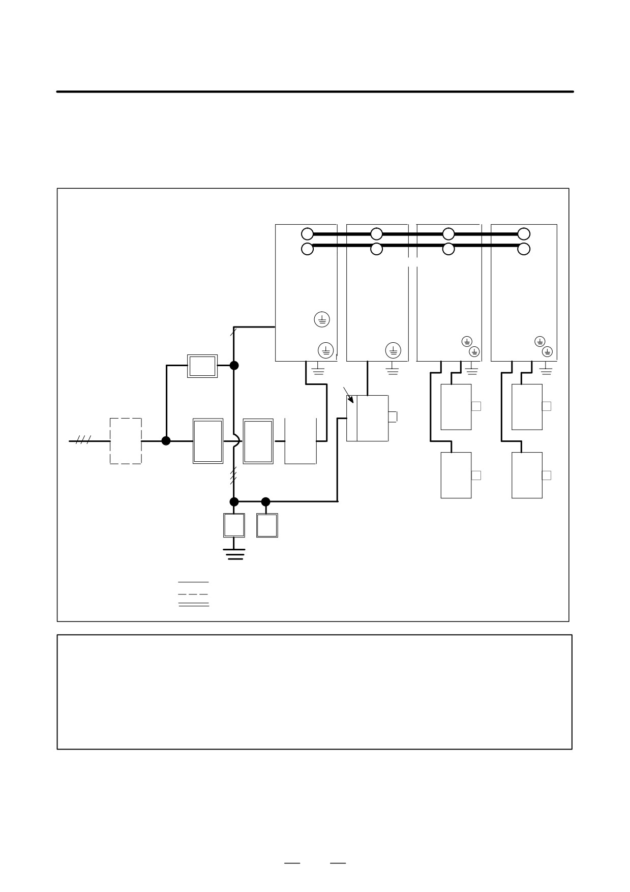
(a) Basic configuration using PSM
The basic configuration is shown below.
(Example having two 2-axes servo amplifier modules and a spindle
amplifier module)
Power supply
Spindle amplifier Servo amplifier Servo amplifier
module
module
module (2-axes) module (2-axes)
Ã
ÃÃ
ÃÃ
ÃÃ
L+
L-
Ã
ÃÃ
ÃÃ
ÃÃ
Ã
ÃÃ(300VDÃÃ
ÃÃ
AC input
ÃÃÃÃÃÃ
for control
PSM
SPM
SVM
SVM
power
SPMC
supply
200R,
Ã
200S
Ã
1φ
Circuit
ÃÃ
ÃÃ
UL VL ÃÃ
UL VL WÃ
Ã
breaker 2
L1 L2 L3
U V W
UM VM WM
UM VM WM
ÃÃ
ÃÃ
ÃÃ
ÃÃ
Fan
motor
Power
Circuit
Magnetic AC
Servo
Servo
transformer
breaker 1
contactor reactor
motor
motor
3φ
Spindle motor
(400VAC)
200VAC
(460VAC)
220VAC
230VAC
Servo
Servo
3φ
motor
motor
Lightening surge
absorbers
: Basic
: Optional
: Units prepared by the machine tool builder
NOTE
1
See Chapter 3 for details of how to combine the power supply module, servo amplifier modules,
and spindle amplifier modules.
2
A magnetic contactor, AC reactor, and circuit breakers are always required.
3
To protect the unit from surge currents caused by lightning, connect surge absorbers between
lines, and between the lines and ground, at the power inlet of the power magnetics cabinet.
See APPENDIX A for details.
29
2. CONFIGURATION AND ORDERING INFORMATION
B-65162E/03
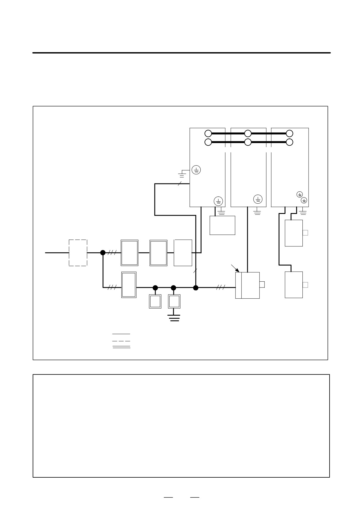
(b) Basic configuration using PSMR
(Example hausing one 2-axes servo amplifier modules and a spindle
amplifier module)
Power supply
Spindle amplifier Servo amplifier
module
module
module (2-axes)
ÃÃ
ÃÃ
Ã
L+
LÃ
Ã
ÃÃ
Ã
ÃÃ ÃÃVDC)
Ã
AC input
PSMR
SPM
SVM
for control
power
ÃÃ
SPMC
supply
ÃÃ
200S,
1φ
RE1 RE2
TH1 TH2
UL VL WL
ÃÃ
ÃÃ
ÃÃ
R S T
U V W
UM VM WM
ÃÃ
ÃÃ
ÃÃ
Power
Circuit
Magnetic AC line
Servo
transformer
200VAC
breaker 1
contactor filter
motor
Regenerative
220VAC
discharge unit
230VAC
Fan
(400VAC)
3φ
motor
(460VAC)
1φ
ÃÃÃ
à Ã
Servo
motor
3φ
à Ã
3φ
Circuit
Spindle motor
Lightening surge
breaker 2
absorbers
: Basic
: Optional
: Units prepared by the machine tool builder
NOTE
1
See Chapter 3 for details of how to combine the power supply module, servo amplifier modules,
and spindle amplifier modules.
2
A magnetic contactor, AC line filter, regenerative discharge unit, and circuit breakers are always
required.
3
To protect the unit from surge currents caused by lightning, connect surge absorbers between
lines, and between the lines and ground, at the power inlet of the power magnetics cabinet.
See APPENDIX A for details.
4
When an insulating transformer is installed, high-frequency noise to the power supply is
reduced, so the AC line filter is not required. If the insulating transformer is installed outside
the power magnetics cabinet, and the cable connecting the amplifier is exposed, the cable must
be covered with a grounded metal duct, or an AC line filter must be installed.
30
2. CONFIGURATION AND ORDERING INFORMATION
B-65162E/03
2.1.2
400-V Input Series
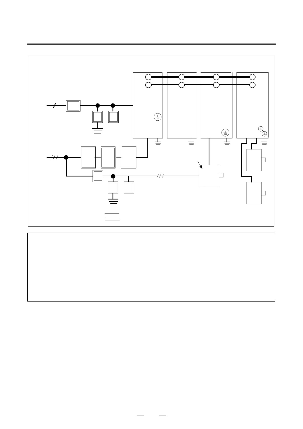
(a) Basic configuration using a PSM-HV
(1) Power supply module (PSM-HV) (Basic)
(2) Capacitor module (PSMC-HV) (Basic)
(3) Servo amplifier module (SVM-HV) (Basic)
(4) Spindle amplifier module (SPM-HV) (Basic)
(5) AC reactor (Basic)
(6) Connectors (for cables) (Basic)
(7) Fuses (Basic)
(8) Fan adaptor (Optional)
(The following example uses one 2-axis servo amplifier module and one
spindle amplifier module.)
31
2. CONFIGURATION AND ORDERING INFORMATION
B-65162E/03
Power supply
Capacitor
Servo amplifier
Servo amplifier
module
module
module
module (2-axes)
L+
ÃÃ
ÃÃ
ÃÃ
ÃÃ
L-
ÃÃ
ÃÃ
ÃÃ
ÃÃ
Control power supply
Ãlink
(DC600V)
Ã
Ã
(AC200V)
AC input
(AC230V)
PSM-HV
PSMC-HV
SPM-HV
SVM-HV
1φ
200R
Circuit
200S,
ÃÃ
breaker 2
ÃÃ
ÃÃ
Lightning surge
UL VL WL
L1 L2 L3
U VÃÃ
UM VM Ã
ÃÃ
protector
Circuit
Magnetic
AC
Ã
Ã
breaker 1
contactor
(AC400V)
reactor
(AC460V)
Fan
motor
Servo
motor
3φ
3φ
Circuit
breaker 3
Spindle motor
Servo
Lightening surge
motor
protector
: Basic configuration
: Equipment to be prepared by the user
NOTE
1
For the control power supply, single-phase 200VAC is required.
2
Install circuit breakers, a magnetic contactor, and AC reactor.
3
At the power supply inlet of the power magnetics cabinet, install lightning surge protectors
between the lines and between a line and ground to protect the equipment from surge voltages
caused by lightning. For details, see Appendix A.
4
Note that when PSM-75HV is used, the position of the PSMC-HV differs from the above
diagram. For the position of the PSMC-HV, see (5) in Section 5.1.
5
Measures must be taken to detect the operation (trip) of circuit breaker 3.
32