FANUC SERVO AMPLIFIER a series. DESCRIPTIONS (B-65162E/03) - page 2
2. CONFIGURATION AND ORDERING INFORMATION
B-65162E/03
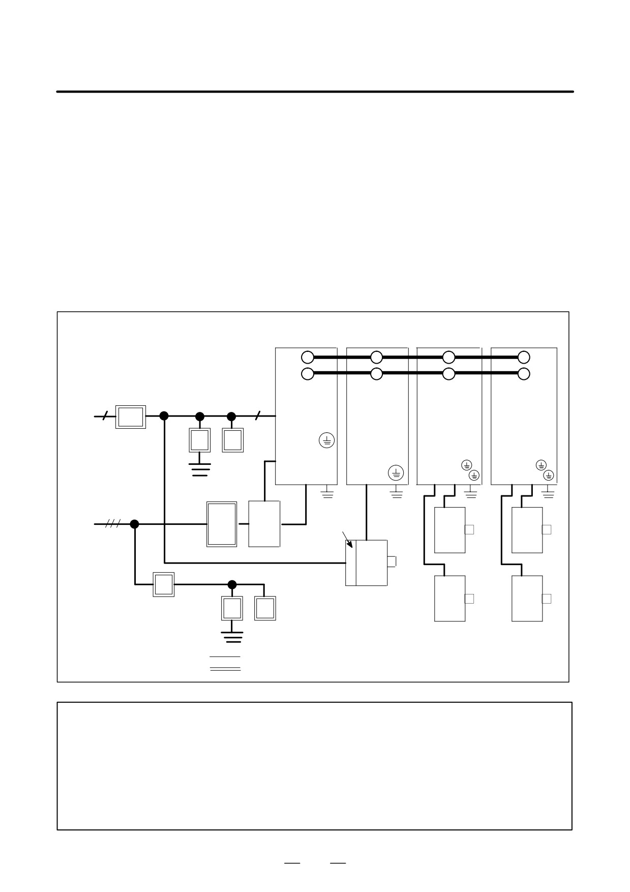
(b) Basic configuration using a PSMV-HV
(1) Power supply module (PSMV-HV) (Basic)
(2) Servo amplifier module (SVM) (Basic)
(3) Spindle amplifier module (SPM) (Basic)
(4) Spindle amplifier module (SPMC) (Basic)
(5) AC reactor unit (Basic)
(6) Connectors (for cables) (Basic)
(7) Fuses (Basic)
(8) Fan adaptor (Optional)
(9) Dynamic brake module (DBM) (Basic)
(The following example uses two 2-axis servo amplifier modules and one
spindle amplifier module.)
Power supply
Spindle amplifier
Servo amplifier
Servo amplifier
module
module
module (2-axes)module (2-axes)
L+
Ã
ÃÃ
ÃÃ
ÃÃ
L-
Ã
ÃÃ
ÃÃ
ÃÃ
DC link
(DC300V)
(AC200V)
(AC230V)
PSMV-HV
PMS
SVM
SVM
1φ
1φ
SPMC
200R
Circuit
200S,
ÃÃ
breaker 2
400R,400SÃ
ÃÃ
ÃÃ
Lightning
surge
400T
UL VL WL
UL VL WL
L1 L2 L3
U V W
UM VÃÃ
UM VM Ã
protector
ÃÃ
Ã
Magnetic
ÃÃ
Ã
Ã
(AC400V)
contactor
(AC460V)
Fan
motor
Servo
Servo
motor
motor
3φ
AC reactor unit
Spindle motor
Servo
Servo
Circuit
Lightening surge
motor
motor
breaker 3
protector
: Basic configuration
: Equipment to be prepared by the user
NOTE
1
For the control power supply, single-phase 200VAC is required.
2
Install a magnetic contactor and AC reactor. Always connect the magnetic contactor closer to
the input power supply than the AC reactor unit.
3
At the power supply inlet of the power magnetics cabinet, install lightning surge protectors
between the lines and between a line and ground to protect the equipment from surge voltages
caused by lightning. For details, see Appendix A.
4
Measures must be taken to detect the operation (trip) of circuit breaker 3.
33
2. CONFIGURATION AND ORDERING INFORMATION
B-65162E/03
2.2
ORDERING
INFORMATION
2.2.1
200-V Input Series
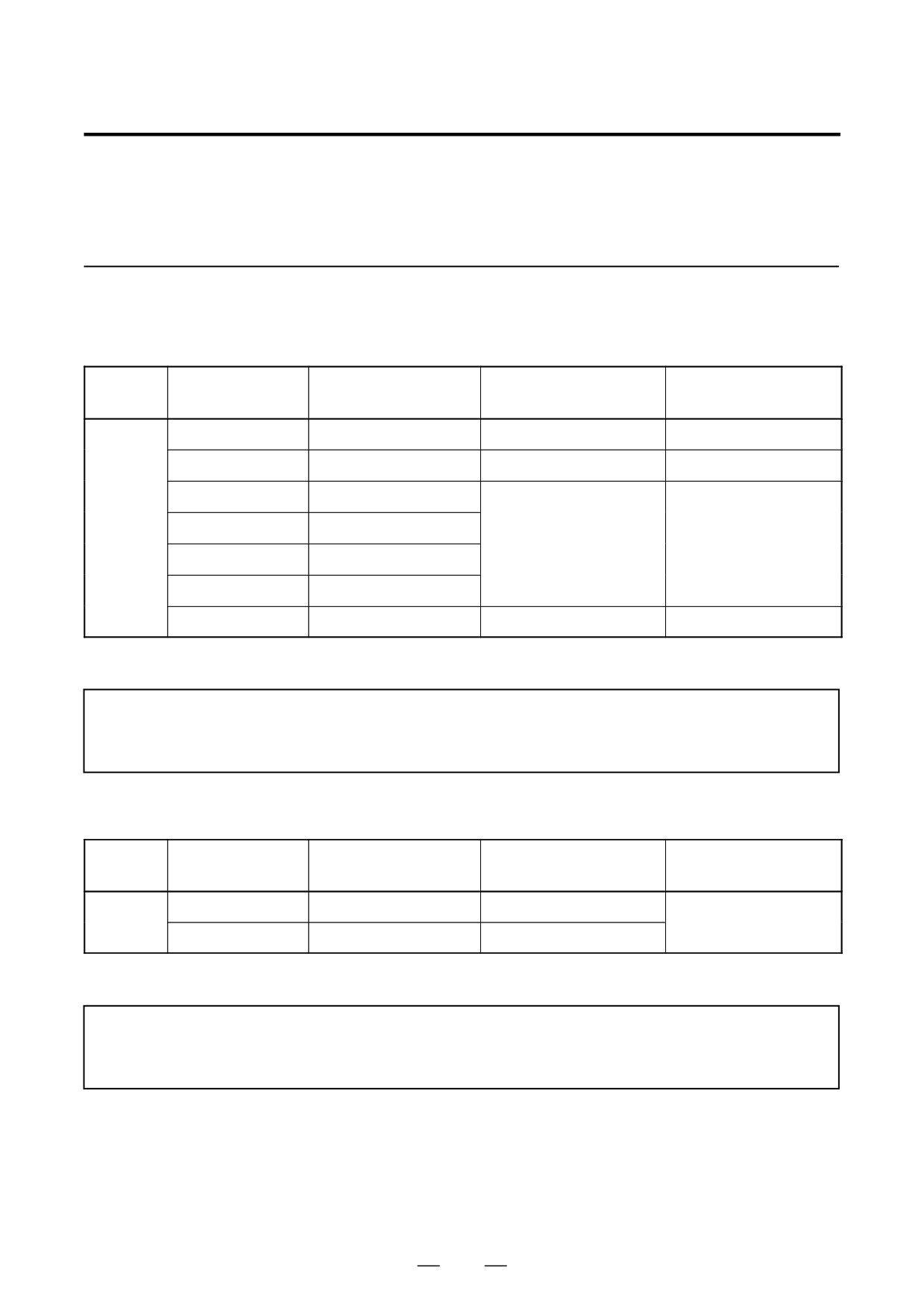
(1) Power Supply Module (PSM)
External dimensions
Category
Name
Ordering number
Remarks
(H x W x D mm)
PSM-5.5
A06B-6077-H106
380
90
307
PSM-11
A06B-6077-H111
380
90
307
(Note)
PSM-15
A06B-6087-H115
Standard
PSM-26
A06B-6087-H126
380
90
307
PSM-30
A06B-6087-H130
PSM-37
A06B-6087-H137
PSM-45
A06B-6087-H145
380
300
307
(Note)
See Section 3.3 for details of how to select the power supply module.
NOTE
PSM-11 and PSM-45 require forced air cooling from the outside. See (7) in Section 2.2.3 and
Chapter 7.
(2) Power Supply Module (PSMR)
External dimensions
Category
Name
Ordering number
Remarks
(H x W x D mm)
PSMR-3
A06B-6081-H103
380
60
172
Standard
PSMR-5.5
A06B-6081-H106
380
60
307
When selecting a PSMR, see Section 3.4.
NOTE
For the PSMR, a regenerative discharge unit is required. See (8) in Section 2.2.3, Section
3.4.5, and Section 8.1.7.
34
2. CONFIGURATION AND ORDERING INFORMATION
B-65162E/03
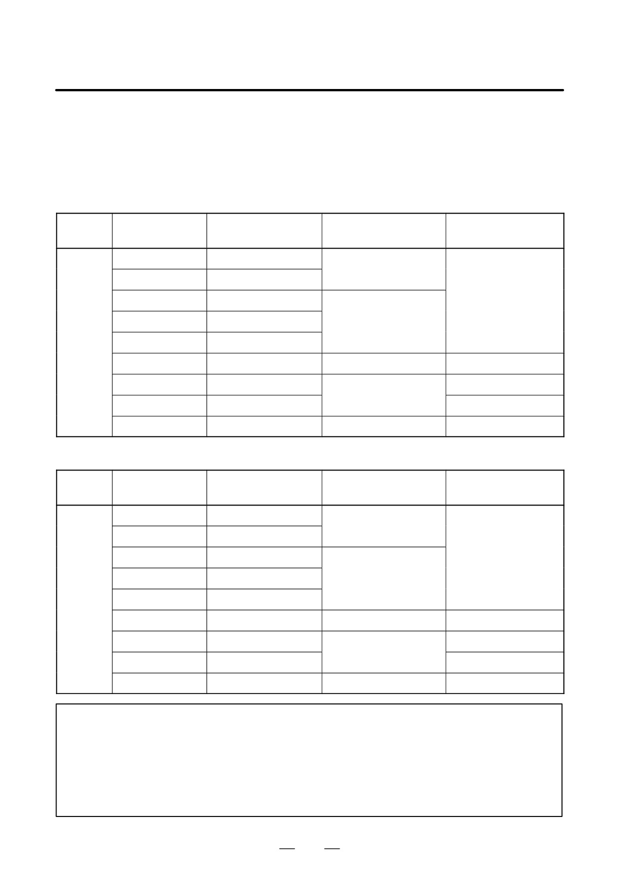
(3) Servo Amplifier Module (SVM)
The ordering drawing number differs depending on the interface with the CNC. Specify an appropriate SVM
for the interface between the CNC and SVM.
- 1-axis servo amplifier module
(a) TYPE A and TYPE B interface
External dimensions
Category
Name
Ordering number
Remarks
(H x W x D mm)
SVM1-12
A06B-6079-H101
380
60
172
SVM1-20
A06B-6079-H102
SVM1-40S
A06B-6079-H103
SVM1-40L
A06B-6079-H104
380
60
307
Standard
SVM1-80
A06B-6079-H105
SVM1-130
A06B-6079-H106
380
90
307
(Note 1)
SVM1-240
A06B-6079-H107
(Note 2)
380
150
307
SVM1-360
A06B-6079-H108
(Note 2)
DBM
A06B-6079-H401
380
100
172
(Note 2)
(b) FSSB interface
External dimensions
Category
Name
Ordering number
Remarks
(H x W x D mm)
SVM1-12
A06B-6096-H101
380
60
172
SVM1-20
A06B-6096-H102
SVM1-40S
A06B-6096-H103
SVM1-40L
A06B-6096-H104
380
60
307
Standard
SVM1-80
A06B-6096-H105
SVM1-130
A06B-6096-H106
380
90
307
(Note 1)
SVM1-240
A06B-6096-H107
(Note 2)
380
150
307
SVM1-360
A06B-6096-H108
(Note 2)
DBM
A06B-6079-H401
380
100
172
(Note 2)
NOTE
1
For the SVM1-130, forced air cooling may be required depending on the motor used. See (7)
in Section 2.2.3 and Chapter 7.
2
A dynamic brake module (DBM) is required whenever the SVM1-240 or SVM1-360 is used.
In the event of an emergency stop, for example, the dynamic brake module stops the motor
immediately by short-circuiting the power line of the motor without PWM control. SVMs other
than SVM1-240 and SVM1-360 have the dynamic brake function built in.
35
2. CONFIGURATION AND ORDERING INFORMATION
B-65162E/03
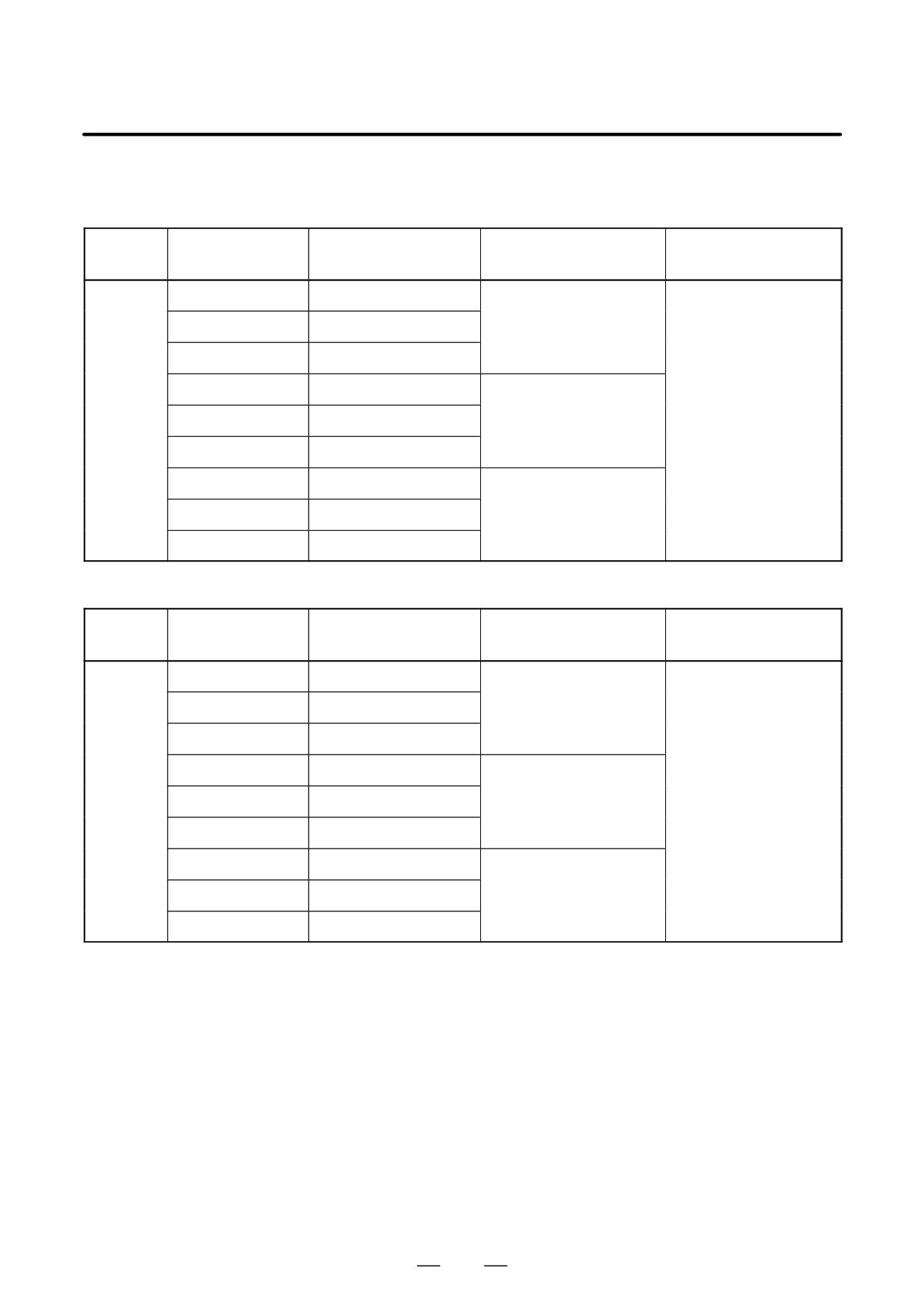
- 2-axis servo amplifier module
(a) TYPE A and TYPE B interface
External dimensions
Category
Name
Ordering number
Remarks
(H x W x D mm)
SVM2-12/12
A06B-6079-H201
SVM2-12/20
A06B-6079-H202
380
60
172
SVM2-20/20
A06B-6079-H203
SVM2-12/40
A06B-6079-H204
Standard
SVM2-20/40
A06B-6079-H205
380
60
307
SVM2-40/40
A06B-6079-H206
SVM2-40/80
A06B-6079-H207
SVM2-80/80
A06B-6079-H208
380
90
307
SVM2-40L/40L
A06B-6079-H209
(b) FSSB interface
External dimensions
Category
Name
Ordering number
Remarks
(H x W x D mm)
SVM2-12/12
A06B-6096-H201
SVM2-12/20
A06B-6096-H202
380
60
172
SVM2-20/20
A06B-6096-H203
SVM2-12/40
A06B-6096-H204
Standard
SVM2-20/40
A06B-6096-H205
380
60
307
SVM2-40/40
A06B-6096-H206
SVM2-40/80
A06B-6096-H207
SVM2-80/80
A06B-6096-H208
380
90
307
SVM2-40L/40L
A06B-6096-H209
36
2. CONFIGURATION AND ORDERING INFORMATION
B-65162E/03
– 3-axis servo amplifier module
(a) TYPE A interface
External dimensions
Category
Name
Ordering number
Remarks
(H x W x D mm)
SVM3-12/12/12
A06B-6079-H301
SVM3-12/12/20
A06B-6079-H302
380
60
172
SVM3-12/20/20
A06B-6079-H303
Standard
SVM3-20/20/20
A06B-6079-H304
SVM3-12/12/40
A06B-6079-H305
SVM3-12/20/40
A06B-6079-H306
380
60
307
SVM3-20/20/40
A06B-6079-H307
(b) TYPE B interface
External dimensions
Category
Name
Ordering number
Remarks
(H x W x D mm)
SVM3-12/12/12
A06B-6080-H301
SVM3-12/12/20
A06B-6080-H302
380
90
172
SVM3-12/20/20
A06B-6080-H303
Standard
SVM3-20/20/20
A06B-6080-H304
SVM3-12/12/40
A06B-6080-H305
SVM3-12/20/40
A06B-6080-H306
380
90
307
SVM3-20/20/40
A06B-6080-H307
(c) FSSB interface
External dimensions
Category
Name
Ordering number
Remarks
(H x W x D mm)
SVM3-12/12/12
A06B-6096-H301
SVM3-12/12/20
A06B-6096-H302
380
90
172
SVM3-12/20/20
A06B-6096-H303
Standard
SVM3-20/20/20
A06B-6096-H304
SVM3-12/12/40
A06B-6096-H305
SVM3-12/20/40
A06B-6096-H306
380
90
307
SVM3-20/20/40
A06B-6096-H307
37
2. CONFIGURATION AND ORDERING INFORMATION
B-65162E/03
(4) Spindle Amplifier Module (SPM)
Ordering numbers depend on the detectors being used (function).
(a) Type 1 (standard specifications)
Detectors used
1. M sensor, position coder, magnetic sensor (for orientation)
2. MZ sensor, BZ sensor (built-in motor)
External dimensions
Category
Name
Ordering number
Remarks
(H x W x D mm)
SPM-2.2
A06B-6078-H202#H500
380
60
307
SPM-5.5
A06B-6078-H206#H500
380
90
307
SPM-11
A06B-6078-H211#H500
380
90
307
(Note)
SPM-15
A06B-6088-H215#H500
Standard
SPM-22
A06B-6088-H222#H500
380
150
307
SPM-26
A06B-6088-H226#H500
SPM-30
A06B-6088-H230#H500
SPM-45
A06B-6088-H245#H500
380
300
307
(Note)
(b) Type 2 (specifications for Cs-axis contouring control or BZ (spindle) sensor)
Applicable detectors :
1. M sensor + BZ sensor (using position coder signals only)
2. High-resolution magnetic pulse coder (for motors only)
3. High-resolution magnetic pulse coder (for motors and spindles)
4. High-resolution position coder + high-resolution magnetic pulse coder
(for motors only)
External dimensions
Category
Name
Ordering number
Remarks
(H x W x D mm)
SPM-2.2
A06B-6078-H302#H500
380
60
307
SPM-5.5
A06B-6078-H306#H500
380
90
307
SPM-11
A06B-6078-H311#H500
380
90
307
(Note)
SPM-15
A06B-6088-H315#H500
Standard
SPM-22
A06B-6088-H322#H500
380
150
307
SPM-26
A06B-6088-H326#H500
SPM-30
A06B-6088-H330#H500
SPM-45
A06B-6088-H345#H500
380
300
307
(Note)
38
2. CONFIGURATION AND ORDERING INFORMATION
B-65162E/03
(c) Type 3 (specifications for spindle switching control or differential speed control)
Applicable detectors :
1. Spindle switching control
(switching the speed only, or switching both the speed and position)
2. Differential speed control (input circuit for position coder signals)
External dimensions
Category
Name
Ordering number
Remarks
(H x W x D mm)
SPM-11
A06B-6078-H411#H500
SPM-15
A06B-6078-H415#H500
SPM-22
A06B-6078-H422#H500
380
150
307
Standard
SPM-26
A06B-6078-H426#H500
SPM-30
A06B-6078-H430#H500
SPM-45
A06B-6088-H445#H500
380
300
307
(Note)
(d) Type 4 (high-resolution internal circuit incorporation specification)
Function used
1. α spindle sensor Cs contour control
External dimensions
Category
Name
Ordering number
Remarks
(H x W x D mm)
SPM-2.2
A06B-6078-H102#H500
380
60
307
SPM-5.5
A06B-6078-H106#H500
380
90
307
SPM-11
A06B-6078-H111#H500
(Note)
SPM-15
A06B-6088-H115#H500
Standard
SPM-22
A06B-6088-H122#H500
380
150
307
SPM-26
A06B-6088-H126#H500
SPM-30
A06B-6088-H130#H500
SPM-45
A06B-6088-H145#H500
380
300
307
(Note)
NOTE
SPM-11 (except type 3) and SPM-45 require forced air cooling from the outside. See (7) in
Section 2.2.3 and Chapter 7.
39
2. CONFIGURATION AND ORDERING INFORMATION
B-65162E/03
(5) αC series Spindle Amplifier Module (SPMC)
External dimensions
Category
Name
Ordering number
Remarks
(H x W x D mm)
SPMC-2.2
A06B-6082-H202#H512
380
60
307
SPMC-5.5
A06B-6082-H206#H512
380
90
307
SPMC-11
A06B-6082-H211#H512
(Note)
Standard
SPMC-15
A06B-6082-H215#H512
SPMC-22
A06B-6082-H222#H512
380
150
307
SPMC-26
A06B-6082-H226#H512
NOTE
SPMC-11 requires forced air cooling from the outside. See (7) in Section 2.2.3 and Chapter
7.
2.2.2
400-V Input Series
(1) Power supply module (PSM-HV)
External dimensions
Category
Name
Ordering number
Remarks
(H x W x D mm)
PSM-18HV
A06B-6091-H118
(Note 1)
PSM-30HV
A06B-6091-H130
380
150
307
(Note 1)
Standard
PSM-45HV
A06B-6091-H145
(Note 1)
PSM-75HV
A06B-6091-H175
380
300
307
(Note 1, 2)
For how to select a PSM, see Section 3.5.
NOTE
1
The PSM-HV requires a capacitor module (PSMC-HV). Specify an appropriate capacitor
module for the PSM-HV being used, according to (2) in Section 2.2.2.
2
The PSM-75HV requires forced air cooling from the outside. See (7) in Section 2.2.3 and
Chapter 7.
40
2. CONFIGURATION AND ORDERING INFORMATION
B-65162E/03
(2) Capacitor module (PSMC-HV)
When using a PSM-HV, specify a capacitor module (PSMC-HV).
External dimensions
Category
Name
Ordering number
Remarks
(H x W x D mm)
PSMC-18HV
A06B-6083-H218
For PSM-18HV
380
90
172
PSMC-30HV
A06B-6083-H230
For PSM-30HV
Standard
For PSM-45HV and
PSMC-45HV
A06B-6083-H245
380
150
222
PSM-75HV
(3) Power supply module (PSMV-HV)
External dimensions
Category
Name
Ordering number
Remarks
(H x W x D mm)
Standard
PSMV-11HV
A06B-6098-H111
380
150
307
NOTE
No capacitor module (PSMC-HV) is required.
(4) Servo amplifier module (SVM-HV)
The ordering drawing number differs depending on the interface with the CNC.
Specify an appropriate SVM-HV for the interface between the CNC and SVM-HV.
- Servo amplifier module (one axis)
(a) TYPE A and TYPE B interfaces
External dimensions
Category
Name
Ordering number
Remarks
(H x W x D mm)
SVM1-20HV
A06B-6085-H102
Standard
SVM1-40HV
A06B-6085-H103
380
90
307
SVM1-60HV
A06B-6085-H104
(b) FSSB interface
External dimensions
Category
Name
Ordering number
Remarks
(H x W x D mm)
SVM1-20HV
A06B-6097-H102
Standard
SVM1-40HV
A06B-6097-H103
380
90
307
SVM1-60HV
A06B-6097-H104
41
2. CONFIGURATION AND ORDERING INFORMATION
B-65162E/03
- Servo amplifier module (two axes)
(a) TYPE A and TYPE B interfaces
External dimensions
Category
Name
Ordering number
Remarks
(H x W x D mm)
SVM2-20/20HV
A06B-6085-H201
SVM2-20/40HV
A06B-6085-H202
SVM2-20/60HV
A06B-6085-H203
Standard
380
90
307
SVM2-40/40HV
A06B-6085-H204
SVM2-40/60HV
A06B-6085-H205
SVM2-60/60HV
A06B-6085-H206
(b) FSSB interface
External dimensions
Category
Name
Ordering number
Remarks
(H x W x D mm)
SVM2-20/20HV
A06B-6097-H201
SVM2-20/40HV
A06B-6097-H202
SVM2-20/60HV
A06B-6097-H203
Standard
380
90
307
SVM2-40/40HV
A06B-6097-H204
SVM2-40/60HV
A06B-6097-H205
SVM2-60/60HV
A06B-6097-H206
(5) Spindle amplifier module (SPM-HV)
The ordering drawing number differs depending on the detector (function) being used.
(a) Type 1 (standard specification)
Detectors used
1 M sensor, position coder, magnetic sensor (for orientation)
2 MZ sensor, BZ sensor (built-in motor)
External dimensions
Category
Name
Ordering number
Remarks
(H x W x D mm)
SPM-11HV
A06B-6092-H211#H500
380
90
307
(Note)
SPM-15HV
A06B-6092-H215#H500
Standard
SPM-26HV
A06B-6092-H226#H500
380
150
307
SPM-45HV
A06B-6092-H245#H500
SPM-75HV
A06B-6092-H275#H500
380
300
307
(Note)
42
2. CONFIGURATION AND ORDERING INFORMATION
B-65162E/03
(b) Type 2 (Cs contour control/BZ sensor (spindle) specification)
Detectors used
1. M sensor (motor) + BZ sensor (spindle) (using position coder signals only)
2. High-resolution magnetic pulse coder (motor only)
3. High-resolution magnetic pulse coder (motor and spindle)
4. High-resolution position coder (spindle) + high-resolution magnetic pulse coder (motor)
External dimensions
Category
Name
Ordering number
Remarks
(H x W x D mm)
SPM-11HV
A06B-6092-H311#H500
380
90
307
(Note)
SPM-15HV
A06B-6092-H315#H500
Standard
SPM-26HV
A06B-6092-H326#H500
380
150
307
SPM-45HV
A06B-6092-H345#H500
SPM-75HV
A06B-6092-H375#H500
380
300
307
(Note)
(c) Type 3 (spindle switch control/differential speed control specification)
Functions used
1. Spindle switch control (switches between speeds only or between speeds and positions)
2. Differential speed control (position coder signal input circuit)
External dimensions
Category
Name
Ordering number
Remarks
(H x W x D mm)
Standard
SPM-75HV
A06B-6092-H475#H500
380
300
307
(Note)
(d) Type 4 (high-resolution internal circuit incorporation specification)
Function used
1. α spindle sensor Cs contour control
External dimensions
Category
Name
Ordering number
Remarks
(H x W x D mm)
SPM-11HV
A06B-6092-H111#H500
380
90
307
(Note)
SPM-15HV
A06B-6092-H115#H500
Standard
SPM-26HV
A06B-6092-H126#H500
380
150
307
SPM-45HV
A06B-6092-H145#H500
SPM-75HV
A06B-6092-H175#H500
380
300
307
NOTE
SPM-11HV and SPM-75HV require forced air cooling from the outside. See (7) in Section
2.2.3 and Chapter 7.
43
2. CONFIGURATION AND ORDERING INFORMATION
B-65162E/03
2.2.3
Others
(1) AC reactor
Category
Name
Ordering number
Remarks
For PSM-5.5 or
A81L-0001-0122
PSM-11
For PSM-15
A81L-0001-0123
For PSM-26
A81L-0001-0120
Standard
For PSM-30
A81L-0001-0124
PSM-45, 75HV
A81L-0001-0133
PSM-18HV,
A81L-0001-0127
30HV, 45HV
For the dimensions of the AC reactors, see Section 8.1.3.
(2) AC reactor unit
Category
Name
Ordering number
Remarks
Standard
PSMV-11HV
A06B-6098-H001
For the dimensions of the AC reactor unit, see Section 8.1.2.
(3) AC line filter
Category
Name
Ordering number
Remarks
For PSMR-3
A81L-0001-0083#3C
Standard
For PSMR-5.5
A81L-0001-0101#C
For the dimensions of the AC line filters, see Section 8.1.4.
(4) Connectors
The ordering drawing number of the connectors required for connection of input/output signals of each
module, and the configuration of each connector, are shown below. For the connector dimensions, see
Appendix D.
- For power supply module (PSM, PSMR)
Category
Name
Ordering number
Remarks
Standard
CX1A, CX3, CX4
A06B-6071-K203
For PSM, PSMR
– Connectors for the power supply module (PSMV)
Category
Name
Ordering number
Remarks
CX1A, CX3, CX4,
Standard
A06B-6098-K200
For PSMV
CX10
44
2. CONFIGURATION AND ORDERING INFORMATION
B-65162E/03
– For servo amplifier module (SVM)
Category
Name
Ordering number
Remarks
A06B-6073-K210
Solder type
Between PSM and SVM or
between SVMs
A06B-6073-K211
Crimp type
Between PSM-SVM,
A06B-6078-K210
Crimp type
SVM–SVM (for SVM1–240
and SVM1-360)
A06B-6078-K211
Solder type
Standard
Connectors
A06B-6073-K212
Solder type
Between NC to SVM
A06B-6073-K213
Crimp type
For pulse coder
A06B-6073-K214
Solder type
Between SVM-DBM (for
A06B-6073-K216
SVM1-240 and SVM1-360)
- For spindle amplifier module (For SPM)
Category
Name
Ordering number
Remarks
A06B-6078-K210
Crimp type
Between PSM and SPM or
between SPMs
A06B-6078-K211
Solder type
For M sensor or MZ sensor or
A06B-6078-K212
Solder type
BZ sensor
Standard
Connectors
Between NC and SPM
A06B-6078-K213
Crimp type
For load meter or speed
meter
A06B-6078-K214
Solder type
For position coder or
A06B-6078-K215
Solder type
magnetic sensor
– For spindle amplifier module (For SPMC)
Category
Name
Ordering number
Remarks
A06B-6073-K210
Solder type
Between PSM and SPMC or
between SPM and SPMC
A06B-6073-K211
Crimp type
A06B-6078-K210
Crimp type
Between PSM-SPMC, SPM-
SPMC (for SPMC-15, 22, 26)
A06B-6078-K211
Solder type
Standard
Connectors
For connecting speed meter
A06B-6078-K212
Solder type
and thermostat
A06B-6078-K213
Crimp type
Between NC and SPMC
A06B-6078-K214
Solder type
For position coder
A06B-6078-K215
Solder type
45
2. CONFIGURATION AND ORDERING INFORMATION
B-65162E/03
NOTE
1
Connectors are classified into either the press-mount type or solder type, depending on the
method used for attaching a cable to a connector. When a connector is specified, therefore,
care is necessary.
2
When attaching a cable to a press-mount type connector, use the special tools prepared by
the manufacturer of the connector. For the tool specifications, see
”Connection tools”
described later.
- Connector configuration
Configuration of A06B-6071-K203
Connector name
Manufacturer
Part number
Quantity
Use
Dimensions
1-178128-3 (housing)
1
D (1)
For control, single-phase
CX1A
AMP Japan, Ltd
200VAC input
1-175218-2 (contact)
3
D (5)
1-178128-3 (housing)
1
D (1)
For emergency stop sig-
CX4
AMP Japan, Ltd
nal
1-175218-2 (contact)
2
D (5)
2-178128-3 (housing)
1
D (2)
For ON/OFF control for
CX3
AMP Japan, Ltd
external MCC
1-175218-2 (contact)
2
D (5)
Configuration of A06B-6073-K210 (solder type)
Connector name
Manufacturer
Part number
Quantity
Use
Dimensions
CX2A
1-178288-3 (housing)
2
D (3)
AMP Japan, Ltd
For control, 24VDC input
CX2B
1-175218-2 (contact)
6
D (5)
JX1A
PCR-E20FS (connector)
2
For PSM-SVM and
D (7)
Honda Tsushin
SVM–SVM communica-
Kogyo Co., Ltd.
JX1B
PCR-V20LA (case)
2
tion
D (10)
Configuration of A06B-6073-K211 (press-mount type)
Connector name
Manufacturer
Part number
Quantity
Use
Dimensions
CX2A
1-178288-3 (housing)
2
D (3)
AMP Japan, Ltd
For control, 24VDC input
CX2B
1-175218-2 (contact)
6
D (5)
JX1A
PCR-E20FA (connector)
2
For PSM-SVM and
D (6)
Honda Tsushin
SVM–SVM communica-
Kogyo Co., Ltd.
JX1B
PCR-V20LA (case)
2
tion
D (10)
Configuration of A06B-6073-K212 (solder type)
Connector name
Manufacturer
Part number
Quantity
Use
Dimensions
JVjA (*1)
PCR-E20FS (connector)
1
D (7)
Honda Tsushin
For CNC-SVM commu-
Kogyo Co., Ltd.
nication
JSjB (*2)
PCR-V20LA (case)
1
D (10)
46
2. CONFIGURATION AND ORDERING INFORMATION
B-65162E/03
Configuration of A06B-6073-K213 (press-mount type)
Connector name
Manufacturer
Part number
Quantity
Use
Dimensions
JVjA (*1)
PCR-E20FA (connector)
1
D (6)
Honda Tsushin
For CNC-SVM commu-
Kogyo Co., Ltd.
nication
JSjB (*2)
PCR-V20LA (case)
1
D (10)
Configuration of A06B-6073-K214 (solder type)
Connector name
Manufacturer
Part number
Quantity
Use
Dimensions
FI40-2015S (connector)
1
D (8)
Hirose Electric
JFjB (*2)
For pulse coder
Co., Ltd.
FI-20-CV (case)
1
D (11)
NOTE
1
Type A interface
2
Type B interface
Configuration of A06B-6073-K215
Connector name
Manufacturer
Part number
Quantity
Use
Dimensions
2-178128-3 (housing)
1
D (2)
CX8
AMP Japan, Ltd
For DB interlock signals
1-175218-2 (contact)
2
D (5)
1-178128-3 (housing)
1
D (1)
CX9
AMP Japan, Ltd
For DB driving coil
1-175218-2 (contact)
2
D (5)
Configuration of A06B-6078-K210 (press-mount type)
Connector name
Manufacturer
Part number
Quantity
Use
Dimensions
CX1A
1-178128-3 (housing)
2
D (1)
For fan motor, 200VAC in-
AMP Japan, Ltd
put
CX1B
1-175218-2 (contact)
4
D (5)
CX2A
1-178288-3 (housing)
2
D (3)
AMP Japan, Ltd
For control, 24VDC input
CX2B
1-175218-2 (contact)
6
D (5)
JX1A
PCR-E20FA (connector)
2
For PSM-SPM and
D (6)
Honda Tsushin
SPM–SPM communica-
Kogyo Co., Ltd.
JX1B
PCR-V20LA (case)
2
tion
D (10)
47
2. CONFIGURATION AND ORDERING INFORMATION
B-65162E/03
Configuration of A06B-6078-K211 (solder type)
Connector name
Manufacturer
Part number
Quantity
Use
Dimensions
CX1A
1-178128-3 (housing)
2
D (1)
For fan motor, 200VAC in-
AMP Japan, Ltd
put
CX1B
1-175218-2 (contact)
4
D (5)
CX2A
1-178288-3 (housing)
2
D (3)
AMP Japan, Ltd
For control, 24VDC input
CX2B
1-175218-2 (contact)
6
D (5)
JX1A
PCR-E20FS (connector)
2
For PSM-SPM and
D (7)
Honda Tsushin
SPM–SPM communica-
Kogyo Co., Ltd.
JX1B
PCR-V20LA (case)
2
tion
D (10)
Configuration of A06B-6078-K212 (solder type)
Connector name
Manufacturer
Part number
Quantity
Use
Dimensions
JY2, JY4
FI40B-20S (connector)
1
D (9)
JY5, JY6
Hirose Electric
See below
αC series
Co., Ltd.
FI-20-CV5 (case)
1
D (12)
JY1
Use: For the M sensor, MZ sensor, BZ sensor, high-resolution position coder, or high-resolution magnetic pulse coder
α C series: For the speed meter, analog override, or motor overheat
Configuration of A06B-6078-K213 (press-mount type)
Connector name
Manufacturer
Part number
Quantity
Use
Dimensions
PCR-E20FA (connector)
1
For CNC-SPM and
D (6)
Honda Tsushin
JA7B
CNC-SPMC commu-
Kogyo Co., Ltd.
PCR-V20LA (case)
1
nication
D (10)
Configuration of A06B-6078-K214 (solder type)
Connector name
Manufacturer
Part number
Quantity
Use
Dimensions
JA7B
PCR-E20FS (connector)
1
D (7)
Honda Tsushin
See below.
Kogyo Co., Ltd.
JY1
PCR-V20LA (case)
1
D (10)
Use JY7B: For CNC-SPM and CNC-SPMC communication
JY1: For the load meter and speed meter (except SPMC)
Configuration of A06B-6078-K215 (solder type)
Connector name
Manufacturer
Part number
Quantity
Use
Dimensions
JY3
FI40B-2015S (connector)
1
D (8)
Hirose Electric
See below.
Co., Ltd.
JY4
FI-20-CV(10) (case)
1
D (11)
Use JY3: For the magnetic sensor and proximity switch
JY4: For the position coder
48
2. CONFIGURATION AND ORDERING INFORMATION
B-65162E/03
Configuration of A06B-6098-K200
Connector name
Manufacturer
Part number
Quantity
Use
Dimensions
1-178128-3 (housing)
1
D (1)
For control, single-phase
CX1A
AMP Japan, Ltd
200VAC input
1-175218-2 (contact)
3
D (5)
1-178128-3 (housing)
1
D (1)
For emergency stop sig-
CX4
AMP Japan, Ltd
nal
1-175218-2 (contact)
2
D (5)
2-178128-3 (housing)
1
D (2)
For ON/OFF control for
CX3
AMP Japan, Ltd
external MCC
1-175218-2 (contact)
2
D (5)
2-178129-6 (housing)
1
D (4)
For phase detection,
CX10
AMP Japan, Ltd
400VAC input
1-175218-2 (contact)
3
D (5)
– Connection tools
Manufacturers of press-mount type connectors provide special tools for attaching the connectors to cables.
(a) Connectors manufactured by AMP Japan, Ltd.
Name
Manufacturer part number
Contact crimping tool
914596-3
Contact extractor
914677-1
(b) Connectors manufactured by Honda Tsushin Kogyo Co., Ltd. (press-mount type connectors only)
Name
Manufacturer part number
Wire placement cassette
JGPS-015-1/1-20
Wire placement cassette mounting base
JGPS-014
Press-mount locator
PCS-K1
Hand press
MFC-K1
(5) Fuses
Fuses are specified as spare parts of the fuses used in modules. The ordering drawing number of the fuses
required for each module and the fuse configuration are shown below.
- For power supply module
Category
Name
Ordering number
Remarks
PSM
A06B-6077-K250
5A/250V, 2A/250V
Standard
PSMR
A06B-6081-K250
5A/250V
PSMV
A06B-6098-K250
5A/250V, 2A/250V, 100A/600V
49
2. CONFIGURATION AND ORDERING INFORMATION
B-65162E/03
- For servo amplifier module
Category
Name
Ordering number
Remarks
Other than SVM1-240, 360
A06B-6073-K250
3.2A/48V
Standard
SVM1-240, 360
A06B-6073-K252
3.2A/48V,0.5A/250V
– Fuse configuration
Configuration of A06B-6073-K250
Manufacturer
Part number
Specification
Use
For short-circuit protection of
Daito Communication Apparatus Co., Ltd.
LM32C
3.2A/48V
24-VDC control power supply
Configuration of A06B-6073-K252
Manufacturer
Part number
Specification
Use
For short-circuit protection of
Daito Communication Apparatus Co., Ltd.
LM32C
3.2A/48V
24-VDC control power supply
For short-circuit protection of
Daito Communication Apparatus Co., Ltd.
HM05
0.5A/250V
200VAC for cooling fan
Configuration of A06B-6077-K250
Manufacturer
Part number
Specification
Use
For short-circuit protection of
Daito Communication Apparatus Co., Ltd.
HM20
2A/250V
200VAC for cooling fan
For short-circuit protection of
Daito Communication Apparatus Co., Ltd.
HM50
5A/250V
200-VAC control power supply
Configuration of A06B-6081-K250
Manufacturer
Part number
Specification
Use
For short-circuit protection of
Daito Communication Apparatus Co., Ltd.
HM50
5A/250V
200-VAC control power supply
Configuration of A06B-6098-K250
Manufacturer
Part number
Specification
Use
For short-circuit protection of
Daito Communication Apparatus Co., Ltd.
HM20
2A/250V
200VAC for cooling fan
For short-circuit protection of
Daito Communication Apparatus Co., Ltd.
HM50
5A/250V
200-VAC control power supply
For short-circuit protection of
Fuji Electric Co., Ltd.
CR6L-100UL
100A/600V
400-VAC main circuit (Note)
NOTE
For the AC reactor unit
50
2. CONFIGURATION AND ORDERING INFORMATION
B-65162E/03
(6) Power transformer
When a power supply module of the 200-V input series is used in an area where the input voltage is not within
the range of 200 to 230VAC, a power transformer is required. The ordering drawing numbers and specifications
of power transformers manufactured by FANUC are listed below.
When other than a FANUC power transformers is to be prepared by the user, it must satisfy the transformer
specifications indicated in (1) of Section 5.2.1.
- Ordering drawing numbers of power transformers manufactured by FANUC
Category
Name
Ordering number
Remarks
For PSMR-3
A80L-0024-0006
(at 2kw output)
For PSMR-3
A80L-0026-0003
(at 3kw output)
For PSM-5.5
For PSMR-5.5
A06B-6052-J001
Power
Primary
380/415/460VAC
(at 5.5kw output)
transformer
Secondary
200VAC
Optional
Power
Primary
380/415/460VAC
For PSM-11
transformer
Secondary
200VAC
For PSMR-5.5
A06B-6044-J006
(at 7.5kw output)
For PSM-15
A06B-6044-J007
For PSM-26, 30
A06B-6044-J010
For PSM-37, 45
A06B-6044-J015
51
2. CONFIGURATION AND ORDERING INFORMATION
B-65162E/03
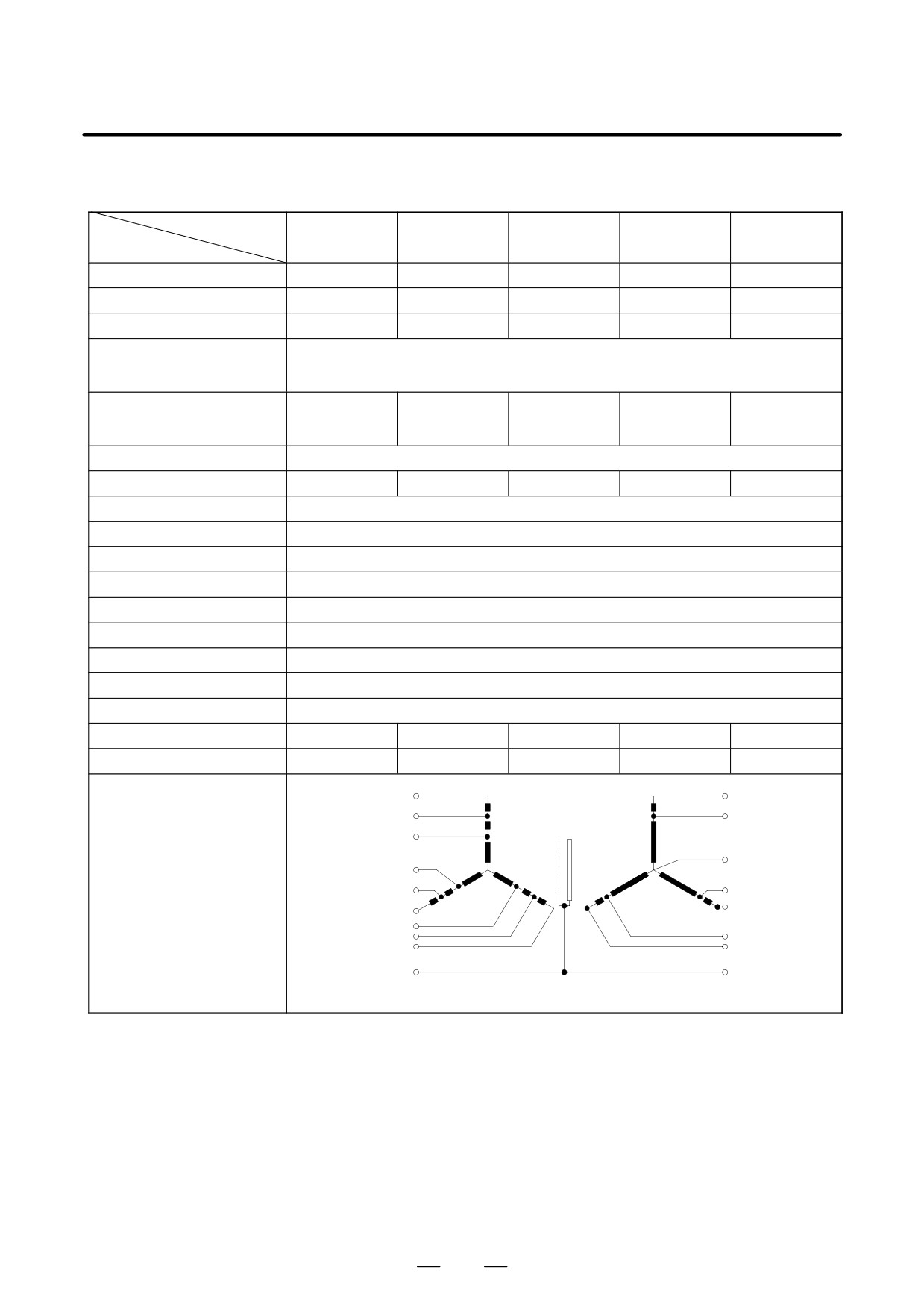
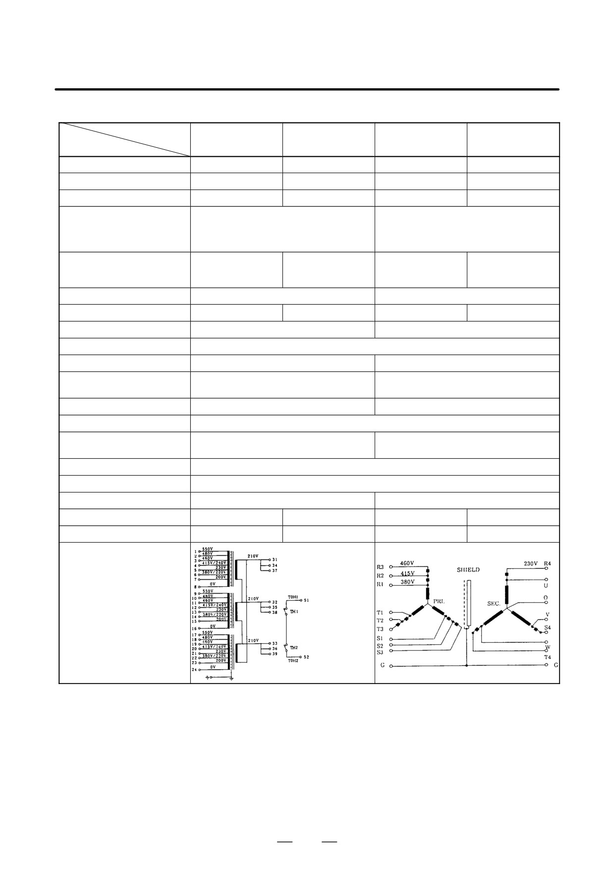
- Specifications of power transformers manufactured by FANUC
Power transformers for PSM
Model
PSM-5.5
PSM-11
PSM-15
PSM-26, 30
PSM-37, 45
Item
Ordering drawing number
A06B-6052-J001
A06B-6044-J006
A06B-6044-J007
A06B-6044-J010
A06B-6044-J015
FANUC drawing number
A80L-0001-0496
A80L-0001-0313
A80L-0001-0314
A80L-0001-0352
A80L-0001-0452
Rated capacity
10kVA
20kVA
30kVA
45kVA
64kVA
380/415/460VAC
Rated primary voltage
230VAC (The secondary is used as an autotransformer.)
+10% -15%, 50/60"1Hz, 3Φ
15A (at 380V)
30A (at 380V)
46A (at 380V)
68A (at 380V)
97A (at 380V)
Rated primary current
14A (at 415V)
28A (at 415V)
42A (at 415V)
63A (at 415V)
89A (at 415V)
13A (at 460V)
25A (at 460V)
38A (at 460V)
56A (at 460V)
80A (at 460V)
Rated secondary voltage
AC200V
Rated secondary current
29A
58A
87A
130A
185A
Voltageregulation at the secondary
5%
Voltage deviation at the secondary
"3%
Connection
Y-Y connection
Insulation
Class H (maximum allowable temperature: 180°C)
Ambienttemperature
0 to 45°C
Allowable temperature rise
135deg
Relative humidity
Max. 95%RH
Type
Dry type, natural air cooling type
Dielectric withstand voltage
2000VAC, for 1 minute
Weight
Max. 61kg
Max. 115kg
Max. 165kg
Max. 260kg
Max. 375kg
Outline drawing
Fig. 8.1.5 (a)
Fig. 8.1.5 (b)
Fig. 8.1.5 (c)
Fig. 8.1.5 (d)
Fig. 8.1.5 (f)
Connection diagram
460V
230V
R3
R4
415V
R2
200V
380V
SHIELD
U
R1
(Newtral point)
PRI.
SEC.
O
T1
T2
V
T3
S4
S1
S2
W
S3
T4
(Primary)
(Secondary)
G
G
52
2. CONFIGURATION AND ORDERING INFORMATION
B-65162E/03
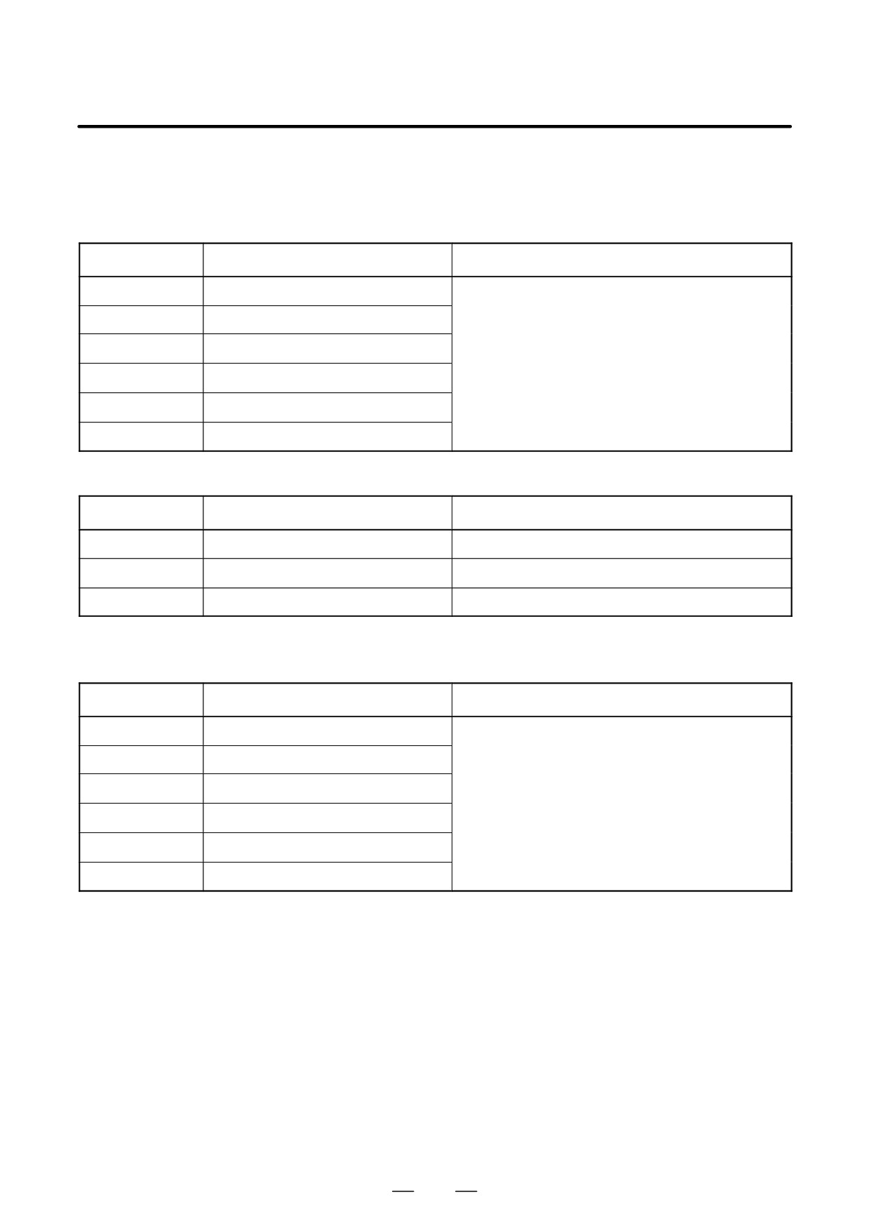
Power transformer for PSMR
Model
PSMR-3
PSMR-3
PSMR-5.5
PSMR-5.5
Item
(at 2 kW output)
(at 3 kW output)
(at 5 kW output)
(at 7.5 kW output)
Ordering drawing number
A80L-0024-0006
A80L-0026-0003
A06B-6052-J001
A06B-6044-J006
FANUC drawing number
A80L-0024-0006
A80L-0026-0003
A80L-0001-0496
A80L-0001-0313
Rated capacity
3.5kVA
5kVA
10kVA
20kVA
380/415/460VAC
200/220/230/240VAC, Δ connection
230VAC (The secondary is used as an auto-
Rated primary voltage
380/415/460/480/550VAC, Y connection
transformer.)
"15%, 50/60Hz"2Hz; 3Φ
+10% -15%, 50/60"1Hz, 3Φ
15A (at 380V)
30A (at 380V)
Rated primary current
5.3A (at 380V)
7.6A (at 380V)
14A (at 415V)
28A (at 415V)
13A (at 460V)
25A (at 460V)
Rated secondary voltage
AC210V
AC200V
Rated secondary current
9.6A
13.7A
29A
58A
Voltageregulation at the secondary
2%
5% (See Fig. 2.2.3 (1).)
Voltage deviation at the secondary
"3%
Connection
Δ-Δ connection or Y-Δ connection
Y-Y connection
Class B
Class H
Insulation
(maximum allowable temperature: 130°C)
(maximum allowable temperature: 180°C)
Ambienttemperature
-20 to 55°C
0 to 45°C
Allowable temperature rise
135deg
Normally closed contact
Thermostat
None
(operating temperature: 135°C)
Relative humidity
Max. 95%RH
Type
Dry type, natural air cooling type
Dielectric withstanding voltage
2300VAC, for 1 minute
2000VAC, for 1 minute
Weight
Max. 27kg
Max. 36kg
Max. 61kg
Max. 115kg
Outline drawing
Fig. 8.1.5 (e)
Fig. 8.1.5 (a)
Fig. 8.1.5 (b)
Connection diagram
200V
(Neutral point)
Connection diagram
(Primary)
(Secondary)
53
2. CONFIGURATION AND ORDERING INFORMATION
B-65162E/03
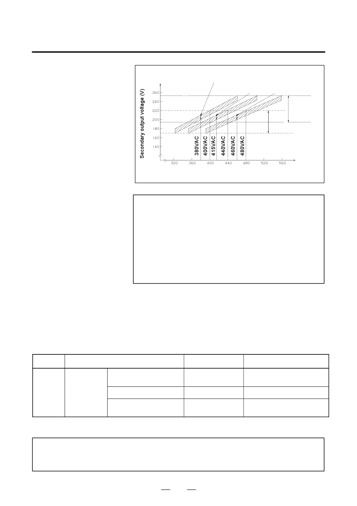
- Connecting a power transformer
Power transformers must be set according to the supply voltage used.
(a) Connection points of power transformers (A80L-0024-0006 and A80L-0026-0003) for PSMR-3
Supply voltage
Connection points at the primary
Other connection points
AC380V
R - 6, S - 14, T - 22
AC400V
R - 4, S - 12, T - 20
AC415V
R - 4, S - 12, T - 20
Make 8-16 and 16-24 connections by using supplied
cables.
AC440V
R - 3, S - 11, T - 19
AC460V
R - 3, S - 11, T - 19
AC480V
R - 2, S - 10, T - 18
Transformer (A80L-0024-0006 and A80L-0026-0003) accessories
Part name
Drawing number
Quantity
Cable
A660-8001-T532
2
Cable
A660-8004-T926
2
Bolt
A30L-0001-0021
4
(b) Connection points of power transformers for PSMR-5.5, PSM-5.5, PSM-11, PSM-15, PSM-26,
PSM-30, PSM-37, and PSM-45
Supply voltage
Connection points at the primary
Remarks
AC380V
R - R1, S - S1, T - T1 (380-V tap)
AC400V
R - R1, S - S1, T - T1 (380-V tap)
AC415V
R - R2, S - S2, T - T2 (415-V tap)
AC440V
R - R2, S - S2, T - T2 (415-V tap)
AC460V
R - R3, S - S3, T - T3 (460-V tap)
AC480V
R - R3, S - S3, T - T3 (460-V tap)
54
2. CONFIGURATION AND ORDERING INFORMATION
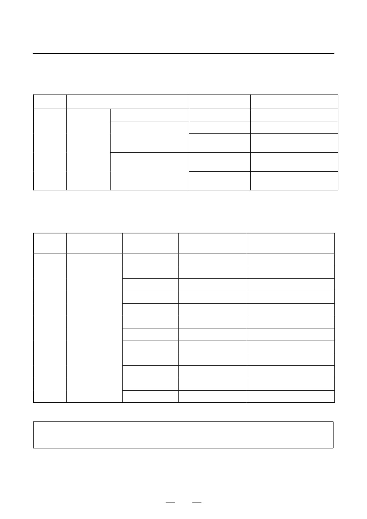
B-65162E/03
Voltage regulation (approximately 10V) when the
load varies (0% to 100%) with the 380-VAC tap set
With the 415-VAC
With the 460-VAC
tap set
tap set
230VAC+10%
-15%
200VAC+10%
-15%
AC input voltage (V)
NOTE
1
When installing a transformer in a cabinet, be careful to
ensure that the transformer does not thermally affect other
equipment. For example, separate the transformer from the
other equipment.
2
When installing a transformer outside the cabinet, make
sure that the transformer is not directly exposed to cutting
chips or coolant.
3
If there is a possibility of the transformer falling, secure the
transformer with bolts or similar.
(7) Fan adaptor
When the following modules are used, forced air cooling is required:
PSM-11, SPM-11, SPM-11HV, SVM1-130(*), SPMC-11, PSM-45, SPM-45, PSM-75HV, SPM-75HV
For the cooling conditions, see Chapter 7.
The use of a fan adaptor allows the desired cooling performance to be obtained. When the fan adaptor is
installed, the panel cut-out must be partially modified. For those modifications, see Section 8.2.
Category
Name
Ordering number
Remarks
For PSM-11 or SPM-11 or
A06B-6078-K001
SPM-11HV
Optional
Fan adaptor
For SVM1-130 or SPMC-11
A06B-6078-K002
PSM-45, SPM-45,
A06B-6078-K003
(Note)
PSM-75HV, SPM-75HV
For the dimensions of fan adaptors, see Section 8.1.6.
NOTE
SVM1-130 requires forced air cooling only when it is being used to drive the α22/3000,
α30/3000, α40/2000 (with a fan), αL25/3000, αL50/2000, or αM40/3000.
55
2. CONFIGURATION AND ORDERING INFORMATION
B-65162E/03
(8) Regenerative discharge unit
Whenever a PSM4 (resistance regeneration type power supply module) is used, a regenerative discharge unit
must be specified. For how to select the regenerative discharge unit, see Section 3.4.5.
Category
Name
Ordering number
Remarks
For PSMR-3
A06B-6081-H050
16Ω/100W (at natural cooling)
A06B-6066-H500
16Ω/200W (at natural cooling)
For PSMR-3, 5.5
16Ω/800W (Forced cooling fan
A06B-6066-H713
Regenerative
motor is included)
Standard
discharge unit
8Ω/800W (Forced cooling fan mo-
A06B-6066-H711
tor is included)
For PSMR–5.5
16Ω/1200W (Forced cooling fan
A06B-6066-H712
motor is included)
See Section 8.1.7, ”SELECTING A REGENERATIVE DISCHARGE UNIT” for details of selection.
(9) Cables
- DC link short bar
Applicable terminal-to-termi-
Category
Name
Between terminals
Ordering number
nal distance
124mm
A06B-6078-K800
120mm - 128mm
90mm
A06B-6078-K801
86mm - 94mm
131mm
A06B-6078-K802
127mm - 135mm
64mm
A06B-6078-K803
60mm - 68mm
85mm
A06B-6078-K804
81mm - 89mm
102mm
A06B-6078-K805
98mm - 106mm
Optional
DC link short bar
146mm
A06B-6078-K823
143mm - 151mm
182mm
A06B-6078-K826
180mm - 185mm
144mm
A06B-6078-K827
142mm - 146mm
305mm
A06B-6078-K828
303mm - 308mm
267mm
A06B-6078-K829
265mm - 269mm
120mm
A06B-6078-K830
118mm - 123mm
See 9.2.1 (2) for details.
NOTE
K823 to K830 are used for 300-mm-wide modules.
56
2. CONFIGURATION AND ORDERING INFORMATION
B-65162E/03
– Cables for connection of modules
Category
Name
Ordering number
Cable length
Remarks
A06B-6078-K808
200mm
(Note 1)
A06B-6078-K809
150mm
A06B-6078-K810
100mm
Cable for connection
Optional
of modules
A06B-6082-K808
200mm
(Note 2)
A06B-6082-K809
150mm
A06B-6082-K810
100mm
NOTE
1
The following three cables are supplied together. The ordering drawing number differs
depending on the cable length.
K4: For 200-VAC power supply for cooling fan (between CX1B and CX1A)
K5: For 24-VDC control power supply (between CX2B and CX2A)
K8: For interface between modules (between JX1B and JX1A)
2
The following two cables are supplied together. The ordering drawing number differs
depending on the cable length.
K5: For 24-VDC control power supply (between CX2B and CX2A)
K8: For interface between modules (between JX1B and JX1A)
- Cables for connection of detectors
Category
Name
Ordering number
Remarks
For M sensor, MZ sen-
A06B-6078-K811
sor or BZ sensor
For magnetic sensor
A06B-6078-K813
A06B-6078-K814
Canon : Straight
For position coder
Optional
A06B-6078-K815
Canon : Elbow
For high resolution
A06B-6078-K816
magnetic pulse coder
A06B-6078-K817
Canon : Straight
For high resolution
position coder
A06B-6078-K818
Canon : Elbow
NOTE
Each cable is 7 m long.
57
2. CONFIGURATION AND ORDERING INFORMATION
B-65162E/03
- FSSB interface cables
Category
Name
Ordering number
Cable length
Remarks
A66L-6001-0023#L150R0
15cm
Internal optical cables
(Note 1)
A66L-6001-0023#L300R0
30cm
A66L-6001-0026#L1R003
1m
A66L-6001-0026#L5R003
5m
FSSB inter-
Optional
A66L-6001-0026#L7R003
7m
face cables
External optical cables
A66L-6001-0026#L10R03
10m
(Note 2)
A66L-6001-0026#L20R03
20m
A66L-6001-0026#L30R03
30m
A66L-6001-0026#L50R03
50m
NOTE
1
Optical cables for connecting SVMs.
SVM (COP10A) - SVM(COP10B)
2
Optical cables for connecting the CNC and SVM.
CNC (COP10A) - SVM (COP10B)
(10) Breaker, Magnetic contactor, Lightning surge absorber
The circuit breaker and magnetic contactor capacities are determined by the power supply module specifications.
The ordering drawing numbers and specifications of the circuit breakers and magnetic contactors are shown below.
For dimensions, see Sections 8.1.9 and 8.1.10.
When this equipment is to be prepared by the user, it must satisfy the circuit breaker and magnetic contactor
specifications indicated below.
- Circuit breaker and magnetic contactor specifications
For PSM and PSMR
PSM name
Circuit breaker 1
Circuit breaker 2
Magnetic contactor
Remarks
PSM-5.5
30A
30A
PSM-11
55A
55A
PSM-15
70A
70A
PSM-26
120A
120A
PSM-30
140A
140A
5A
PSM-37
175A
175A
PSM-45
220A
220A
PSMR-3
20A
20A
30A
30A
(Note 4)
PSMR–5.5
50A
50A
(Note 5)
58
2. CONFIGURATION AND ORDERING INFORMATION
B-65162E/03
NOTE
1
For the installation positions of the circuit breakers and magnetic contactor, see Section 2.1.
2
Circuit breakers 1 and 2 must have a rated voltage of 200VAC or higher.
3
The current and voltage of the operation coil of the magnetic contactor must be within the rating
of the internal contact [CX3 (MCC)] of the PSM. For details, see (6) in Section 9.2.1.
4
When PSMR-5.5 is used with a rated output capacity of 5.5 kW
5
When PSMR-5.5 is used with a rated output capacity of 7.5 kW
For PSM-HV and PSMV-HV
PSM name
Circuit breaker 1
Circuit breaker 2
Circuit breaker 2
Magnetic contactor
Remarks
PSM-18HV
45A
45A
PSM-30HV
75A
75A
3A
3A
PSM-45HV
125A
135A
PSM-75HV
200A
200A
PSMV-11HV
-
5A
5A
60A
NOTE
1
For the installation positions of the circuit breakers and magnetic contactor, see Section 2.1.
2
Circuit breakers 1 and 3 must have a rated voltage of 400VAC or higher.
3
Circuit breaker 2 must have a rated voltage of 200VAC or higher.
4
The current and voltage of the operation coil of the magnetic contactor must be within the
ratings of the internal contact [CX3 (MCC)] of the PSM. For details, see (6) in Section 9.2.1.
59
2. CONFIGURATION AND ORDERING INFORMATION
B-65162E/03
- Ordering drawing numbers of circuit breakers
Outline
Circuit breaker specifi-
Circuit breaker cover
Category
Model
Ordering number
drawing
cation
specification
PSMR-3
A06B-6077-K101
8-1-9-(a)
Fuji Electric EA53B/30
Fuji Electric BZ-TB20B-3
PSMR-5.5,
PSM-5.5
A06B-6077-K102
8-1-9-(b)
Fuji Electric EA103B/50
Fuji Electric BZ-TB20B-3
PSM-18HV
PSM-11
A06B-6077-K103
8-1-9-(c)
Fuji Electric EA103B/60
Fuji Electric BZ-TB20B-3
PSM-15,
A06B-6077-K104
8-1-9-(d)
Fuji Electric EA103B/75
Fuji Electric BZ-TB20B-3
PSM-30HV
PSM-45HV
A06B-6077-K108
8-1-9-(e)
Fuji Electric EA203B/125
Fuji Electric BZ-TB40B
Optional
PSM-26,
A06B-6077-K105
8-1-9-(f)
Fuji Electric EA203B/150
Fuji Electric BZ-TB40B
PSM-30
PSM-37
A06B-6077-K110
8-1-9-(g)
Fuji Electric EA203B/175
Fuji Electric BZ-TB40B
PSM-75HV
A06B-6077-K109
8-1-9-(h)
Fuji Electric EA203B/200
Fuji Electric BZ-TB40B
PSM-45
A06B-6077-K107
8-1-9-(i)
Fuji Electric EA203B/225
Fuji Electric BZ-TB40B
For control
A06B-6077-K106
8-1-9-(j)
Fuji Electric EA33/5
Fuji Electric BZ-TB10B-503
power supply
– Ordering drawing numbers of magnetic contactors
Outline
Magnetic contactor
Magnetic contactor cover
Category
Model
Ordering number
drawing
specification
specification
PSMR-3
A06B-6077-K121
8-1-10-(a)
Fuji Electric SC-5-1
Fuji Electric SZ-JC4
PSMR-5.5,
PSM-5.5
A06B-6077-K122
8-1-10-(b)
Fuji Electric SC-1N
Fuji Electric SZ-1N/T
PSM-18HV
PSM-11,
PSM-30HV
A06B-6077-K123
8-1-10-(b)
Fuji Electric SC-2N
Fuji Electric SZ-1N/T
PSMV-11HV
Optional
PSM-15
A06B-6077-K124
8-1-10-(c)
Fuji Electric SC-2SN
Fuji Electric SZ-2SN/T
PSM-26,
A06B-6077-K125
8-1-10-(d)
Fuji Electric SC-4N
Fuji Electric SZ-4N/T
PSM-45HV
PSM-30
A06B-6077-K126
8-1-10-(e)
Fuji Electric SC-5N
Fuji Electric SZ-5N/T
PSM-37,
A06B-6077-K128
8-1-10-(g)
Fuji Electric SC-7N
Fuji Electric SZ-5N/T
PSM-75HV
PSM-45
A06B-6077-K127
8-1-10-(f)
Fuji Electric SC-8N
Fuji Electric SZ-8N/T
NOTE
The coil voltage specification of the magnetic contactor is 200VAC.
60
2. CONFIGURATION AND ORDERING INFORMATION
B-65162E/03
– Recommended parts
Parts manufactured by Fuji Electric Co., Ltd.
PSM name
Circuit breaker 1
Circuit breaker 2
Circuit breaker 2
Magnetic contactor
Remarks
PSM-5.5
EA103B/50
SC-1N
PSM-11
EA103B/60
SC-2N
PSM-15
EA103B/75
SC-2SN
PSM-26
EA203B/150
SC-4N
PSM-30
EA203B/150
EA33/5
-
SC-5N
PSM-37
EA203B/175
SC-7N
PSM-45
EA203B/225
SC-8N
PSMR-3
EA53B/30
SC-5-1
PSMR-5.5
EA103B/50
SC-1N
PSM-18HV
EA103B/50
SC-1N
PSM-30HV
EA103B/75
SC-2SN
EA33/3
EA33/3
PSM-45HV
EA203B/125
SC-4N
PSM-75HV
EA203B/200
SC-7N
PSMV-11HV
-
EA33/5
EA33/5
SC-2N
NOTE
For details, see the brochures available from Fujitsu Electric Co., Ltd. Note that the
specification of the coil voltage of a magnetic contactor may differ depending on the supply
voltage and frequency used.
(11) Lightning surge protector
To protect equipment from surge voltages caused by lightning, install a lightning surge protector between lines and
between a line and ground. For how to install protectors, see Appendix A. For the outline drawings of lightning surge
protectors, see Section 8.1.11.
Category
Ordering number
Specification
Outline drawing
Remarks
For line-to-line installation:
AC200V
RAV-781BYZ-2
A06B-6077-K142
Fig. 8.1.11 (a)
For 200-VAC line
For line-to-ground installation:
(Note 1)
RAV-781BXZ-4
Optional
For line-to-line installation:
AC400V
RAV-152BYZ-2A
A06B-6077-K143
Fig. 8.1.11 (b)
For 400-VAC line
For line-to-ground installation:
(Note 2)
RAV-801BXZ-4
61
2. CONFIGURATION AND ORDERING INFORMATION
B-65162E/03
NOTE
1
For the 200-V input series main power supply and control power supply, and the 400-V input
series control power supply
2
For the 400-V input series main power supply
3
Tûv approved products
– Recommended products
Line-to-line
Line-to-ground
Remarks
RAV-781BYZ-2 manufactured by
RAV-781BXZ-4 manufactured by
For 200-VAC line
Okaya Electric Industries Co., Ltd.
Okaya Electric Industries Co., Ltd.
RAV-152BYZ-2A manufactured by
RAV-801BYZ-4 manufactured by
For 400-VAC line
Okaya Electric Industries Co., Ltd.
Okaya Electric Industries Co., Ltd.
(12)
Noise filter
A noise filter must be installed in the PSM input section to satisfy the requirements of the EMC Directives which
are now being enforced in the EU countries. For how to select the current capacity and noise filter installation, see
Section 5.3.
Recommended noise filters are listed below.
HF3000C-TMA series manufactured by SOSHIN ELECTRIC CO., LTD.
Part number (SOSHIN ELECTRIC)
Rated current
Rated voltage
Remarks
HF3005C-TMA
5A
HF3010C-TMA
10A
HF3015C-TMA
15A
HF3020C-TMA
20A
HF3030C-TMA
30A
HF3040C-TMA
40A
Leakage current:
HF3050C-TMA
50A
AC460V
5.3 mA max
at 460VAC,60 Hz
HF3060C-TMA
60A
HF3080C-TMA
80A
HF3100C-TMA
100A
HF3150C-TMA
150A
HF3200C-TMA
200A
HF3250C-TMA
250A
For details, refer to the brochures supplied by SOSHIN ELECTRIC CO., LTD.
62