FANUC SERVO AMPLIFIER a series. DESCRIPTIONS (B-65162E/03) - page 8
B-65162E/03
9.CONNECTION
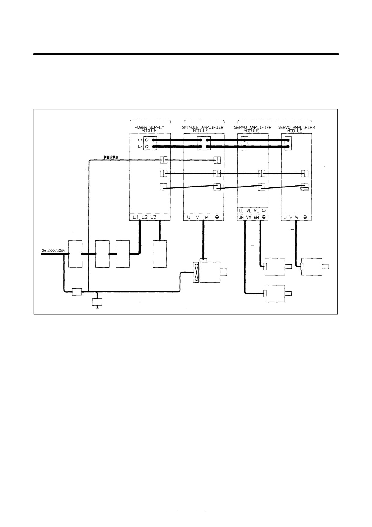
The following connection diagram is an example of combining a PSC,
9.1
SPM, 2-axis SVM, and a 1-axis SVM. For detailed descriptions about
COMPLETE
how to connect these units, see their respective connection diagrams.
CONNECTION
DIAGRAM
See 9.2.1.
See 9.2.2.
See 9.2.3.
Terminating
connector
Input
Servo
Servo
Spindle
motor
motor
Circuit
Magnetic AC
Regenerative dis-
breaker 1
contactor line filter
charge unit
motor
(required when a
PSMR is used)
Fan motor
Servo
motor
Circuit breaker 2
Lightning surge protector
213
9. CONNECTION
B-65162E/03
9.2
CABLE CONNECTION
DETAILS
9.2.1
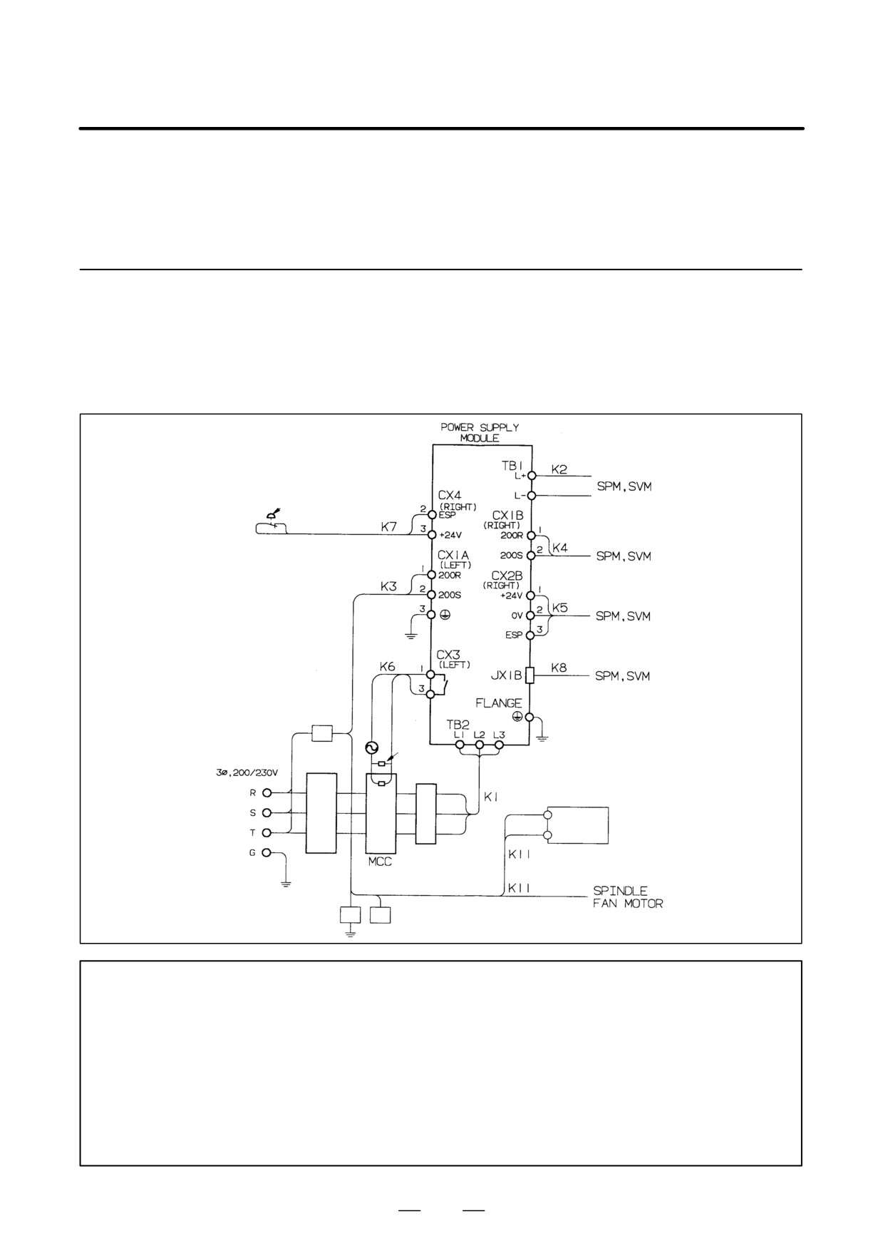
Power Supply Module
Connection Diagram
Power supply module (PSM)
Emergency stop contact
Con-
trol
power
supply
Circuit breaker
2
Spark
Input
killer
Coil
Main power sup-
Cooling
ply
fan
For the PSM-45 only
Circuit
AC reactor
breaker
1
Cabinet
Lightning surge protector
NOTE
1
Always install the circuit breakers, magnetic contactor, and AC reactor.
2
To protect the equipment from lightning surge voltages, install a lightning surge protector across
each pair of power lines and across each power line and the grounding line at the power inlet
of the power magnetics cabinet. See Appendix A for details.
3
Always connect the control power supply cable to the CX1A. If it is connected to the CX1B,
fuses inside the unit may blow.
4
See Section 5.2.3 for the type of the cable to be used for making a connection to a frame
ground.
5
Using a fan adapter in the SPM-11 requires cable K4 (across the CX1B and CX1A).
214
B-65162E/03
9.CONNECTION
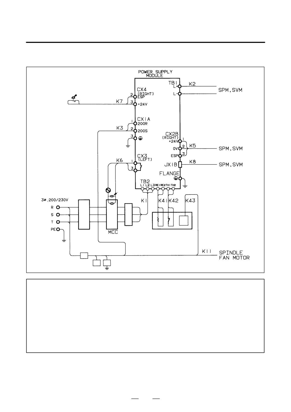
Power supply module (PSMR)
Emergency stop contact
Control
power
supply
Spark killer
Input
Coil
Main pow-
er supply
Thermostat Fan motor
AC reactor
Circuit
Regenerative
breaker
1
discharge unit
Cabinet
Circuit
breaker 2
Lightning
surge protector
NOTE
1
Always install the circuit breakers, magnetic contactor, and AC reactor.
2
To protect the equipment from lightning surge voltages, install a lightning surge protector across
each pair of power lines and across each power line and the grounding line at the power inlet
of the power magnetics cabinet. See Appendix A for details.
3
Always connect the control power supply cable to the CX1A. If it is connected to the CX1B,
fuses inside the unit may blow.
4
See Section 5.2.3 for the type of the cable to be used for making a connection to a frame
ground.
5
If the PSMR is combined with the SPM-11 (with the fan adapter), the way cables K3 and K4
are connected will vary from that shown in this diagram. See the diagram on the next page.
215
9. CONNECTION
B-65162E/03
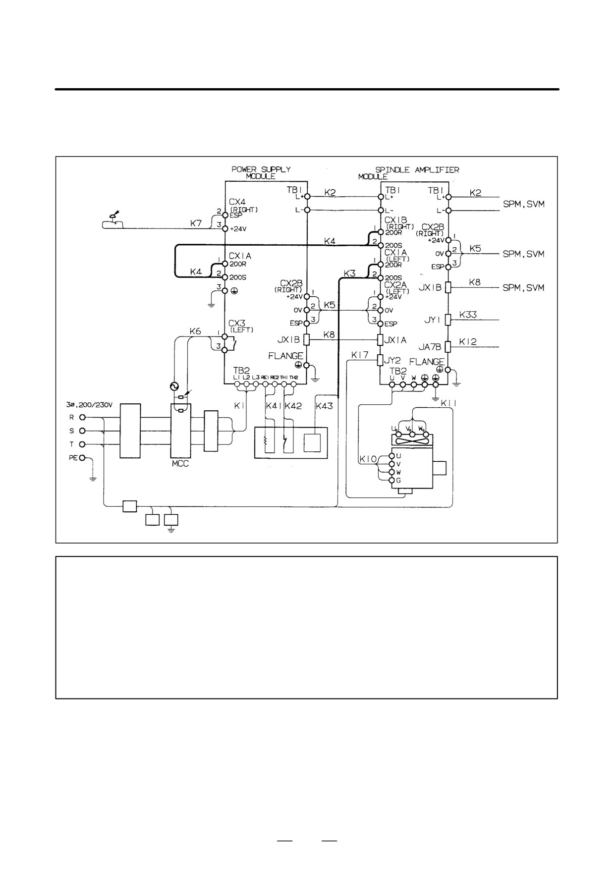
Power supply module (PSMR)
Connected to the SPM-11 (with fan adapter)
(SPM-11 with fan unit)
Emergency stop contact
Control power supply
To load meter/
speedometer
To CNC unit
From
built-in
sensor
Spark killer
or
Input
pulse
genera-
tor
Coil
Fan
motor
Spindle
Circuit
AC line filter
Regenerative
motor
breaker 1
discharge unit
Cabinet
Circuit
breaker 2
Lightning surge protector
NOTE
1
Connect cable K3 to the CX1A (LEFT) of the SPM. See 9.2.1-(3).
2
Connect cable K4 across the CX1B (RIGHT) of the SPM and the CX1A of the PSMR. See
9.2.1-(4).
3
Always install the circuit breakers, magnetic contactor, and AC line filter.
4
To protect the equipment from lightning surge voltages, install a lightning surge protector across
each pair of power lines and across each power line and the grounding line at the power inlet
of the power magnetics cabinet. See Appendix A for details.
5
See Section 5.2.3 for the type of the cable to be used for making a connection to a frame
ground.
216
B-65162E/03
9.CONNECTION
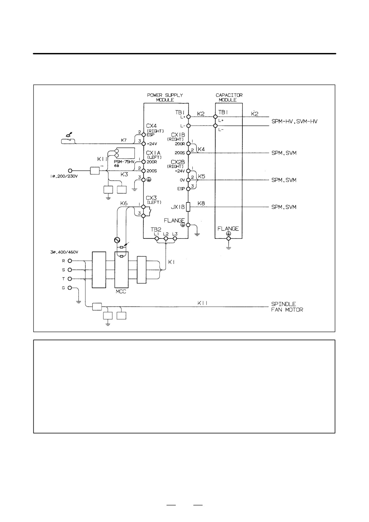
Power supply module (PSM-HV)
Emergency stop contact
Cooling
fan
Control
power supply
Lightning surge protector
Spark killer
Input
Coil
Main
power
supply
Circuit
AC reactor
breaker
1
Cabinet
Circuit
Lightning surge protector
breaker 3
NOTE
1
Always install the circuit breakers, magnetic contactor, and AC reactor.
2
To protect the equipment from lightning surge voltages, install a lightning surge protector across
each pair of power lines and across each power line and the grounding line at the power inlet
of the power magnetics cabinet. See Appendix A for details.
3
Always connect the control power supply cable to the CX1A. If it is connected to the CX1B,
fuses inside the unit may blow.
4
See Section 5.2.3 for the type of the cable to be used for making a connection to a frame
ground.
5
Using a fan adapter in the SPM-11 requires cable K4 (across the CX1B and CX1A).
6
Provide a means of detecting whether circuit breaker 3 has tripped.
217
9. CONNECTION
B-65162E/03
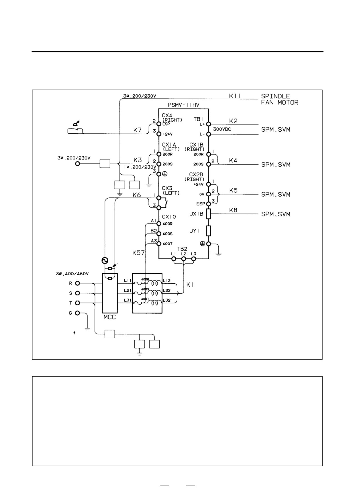
Power supply module (PSMV-HV)
Emergency stop contact
Control power supply
Circuit breaker 2
Lightning surge protector
For test by FANUC
Flange
Spark killer
Input
Coil
Main pow-
er supply
AC reactor unit
Cabinet
Circuit breaker 3
Lightning surge protector
NOTE
1
Always install the magnetic contactor and AC reactor unit.
2
To protect the equipment from lightning surge voltages, install a lightning surge protector across
each pair of power lines and across each power line and the grounding line at the power inlet
of the power magnetics cabinet. See Appendix A for details.
3
Always connect the control power supply cable to the CX1A. If it is connected to the CX1B,
fuses inside the unit may blow.
4
See Section 5.2.3 for the type of the cable to be used for making a connection to a frame
ground.
5
The use of a fan adapter in the SPM-11 requires cable K4 (across the CX1B and CX1A).
6
Provide a means of detecting whether circuit breaker 3 has tripped.
218
B-65162E/03
9.CONNECTION
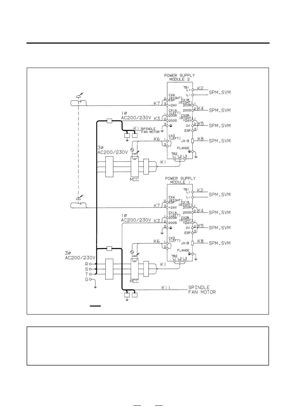
Connection diagram for using two power supply modules
Emergency stop contact
Control power supply
Circuit breaker
2-2
Lightning surge protector
Spark killer
Coil
Circuit breaker
AC reactor
1-2
Emergency stop contact
Control power supply
Circuit breaker
2-1
Spark killer
Coil
Main power supply
Circuit breaker
AC reactor
1-1
Cabinet
Lightning surge protector
Make the wires indicated by the solid line as short as possible.
NOTE
1
Circuit breakers 1 and 2, the magnetic contactors, and the AC reactors cannot be shared. They
must have the rating that matches each power supply module.
2
The lightning surge protector can be shared. Make the wires indicated by the solid line as short
as possible.
219
9. CONNECTION
B-65162E/03
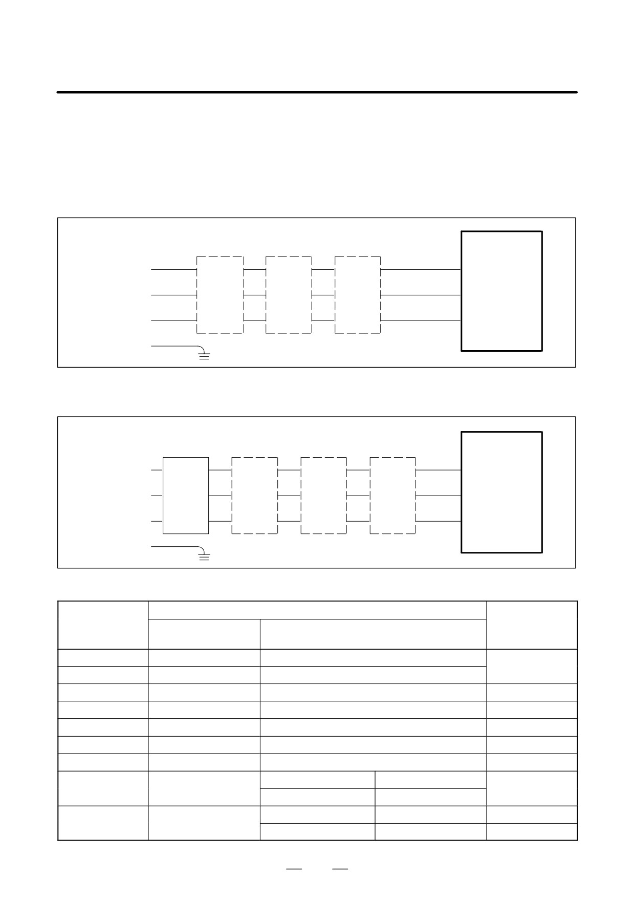
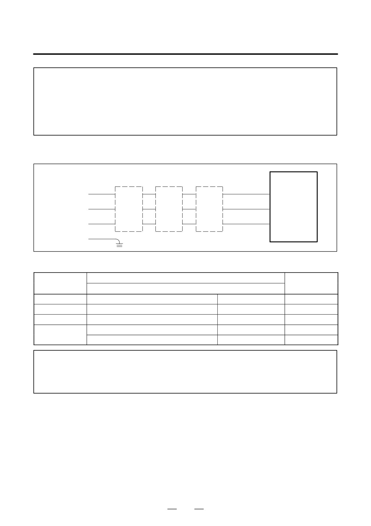
(1) Detailed descriptions about the connection of cable K1 (power supply line)
Cable K1 is used to supply main power to the power supply module. Make sure that the cable used between the
power supply and power supply module satisfies the requirements listed in Table 9.2.1.
- Connection with the PSM and PSMR
(a) For a power supply voltage of 200 to 230 VAC
TB2
PSM
PSMR
L1
Main power
R
(L1)
supply
L2
Circuit
AC
AC200V
S
MCC
(L2)
breaker 1
reactor
AC220V
L3
AC230V
T
(L3)
50/60Hz
G
(b) For a power supply voltage that falls outside the range of 200 to
230 VAC
TB2
PSM
PSMR
L1
Main power
R
(L1)
supply
Power
L2
AC380V
Circuit
AC
S
trans
(L2)
MCC
AC415V
former
breaker 1
reactor
L3
AC460V
T
(L3)
50/60Hz
G
Table.9.2.1 (a) Cable K1 Specifications
Applicable cable
Model
Terminal screw
Heavy-duty power
Heat-resistant cable (Note 2)
cable (Note 1)
PSMR-3
3.5 mm2 or larger
3.5 mm2 or larger
M4 (Note 3)
PSMR-5.5
5.5 mm2 or larger
5.5 mm2 or larger
PSM-5.5
5.5 mm2 or larger
5.5 mm2 or larger
M4
PSM-11
---
8 mm2 or larger
M4 (Note 3)
PSM-15
14 mm2 or larger
14 mm2 or larger
M6
PSM-26
---
22 mm2 or larger
M6
PSM-30
---
22 mm2 or larger
M6
R, S, and T phase lines
38mm2 or larger
PSM-37
–--
M6 (Note 3)
Ground line
22mm2 or larger
R, S, and T phase lines
50mm2 or larger
M10
PSM-45
---
Ground line
22mm2 or larger
M6 (Note 3)
220
B-65162E/03
9.CONNECTION
NOTE
1
Four-conductor polyvinyl heavy-duty power cable (JIS C3312)
2
Fire-retardant polyflex wire (maximum conductor temperature 105°C) or equivalent to LMFC
manufactured by The Furukawa Electric Co., Ltd.
3
Applicable crimp terminals:
5.5-4S for the PSMR-3 and -5.5
8-4S for the PSM-11
38-6S for the PSM-37
- Connection with the PSM-HV
TB2
PSM-HV
L1
Main power
R
(L1)
supply
L2
Circuit
AC
AC400V
S
MCC
(L2)
breaker 1
reactor
AC460V
L3
T
(L3)
50/60Hz
G
Table.9.2.1 (b) Cable K1 Specifications
Applicable cable
Model
Terminal screw
Heat-resistant cable (Note 1)
PSM-18HV
R, S, and T phase lines and grounding line
8mm2 or larger
M6
PSM-30HV
R, S, and T phase lines and grounding line
14mm2 or larger
M6
PSM-45HV
R, S, and T phase lines and grounding line
22mm2 or larger
M6
R, S, and T phase lines
38mm2 or larger
M10
PSM-75HV
Ground line
22mm2 or larger
M6
NOTE
1
Four-conductor polyvinyl heavy-duty power cable (JIS C3312)
2
Fire-retardant polyflex wire (maximum conductor temperature 105°C) or equivalent to LMFC
manufactured by The Furukawa Electric Co., Ltd.
221
9. CONNECTION
B-65162E/03
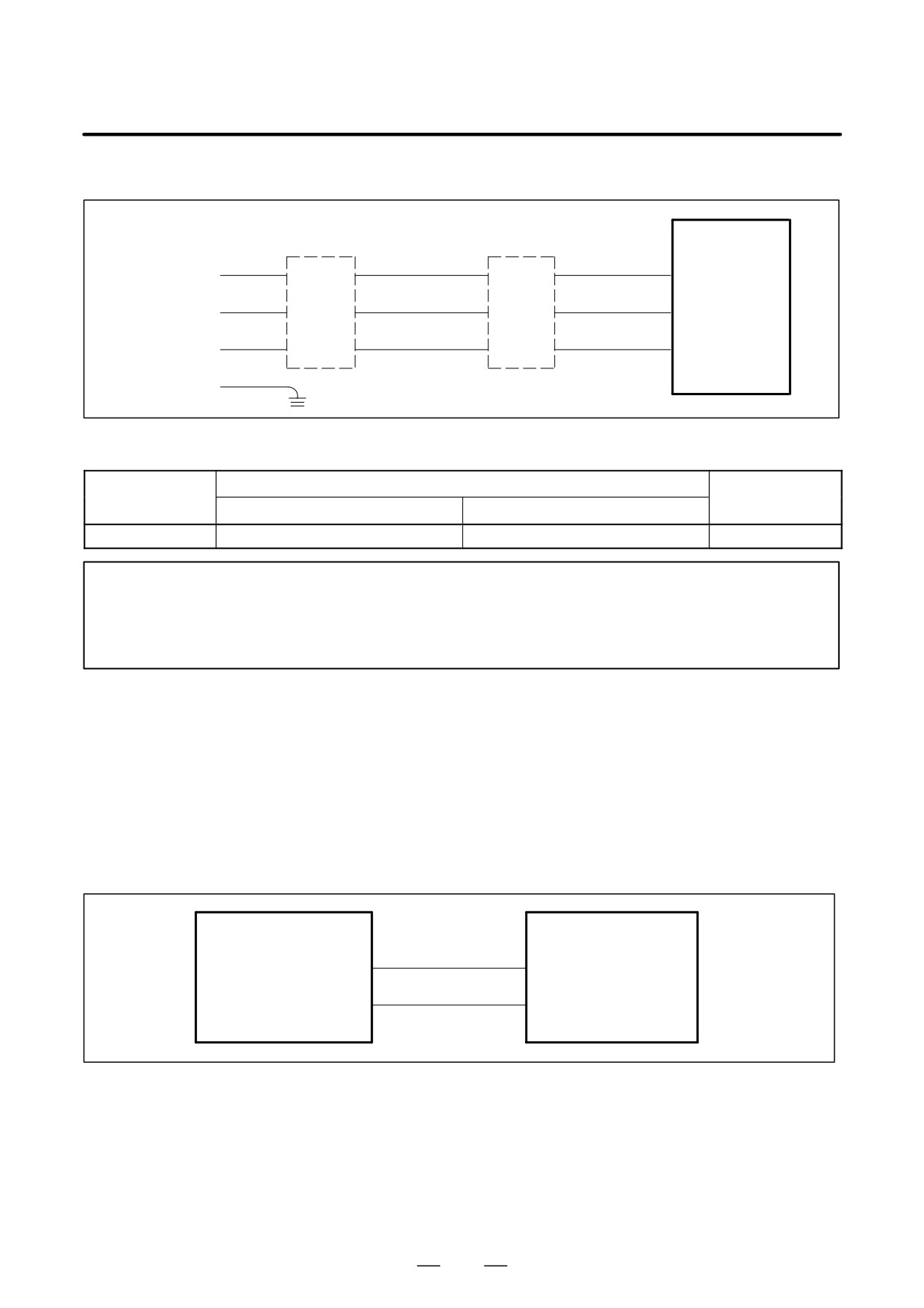
– Connection with the PSMV-HV
TB2
PSMV-
HV
L1
Main power
R
(L1)
supply
AC
L2
AC400V
S
MCC
reactor
(L2)
AC460V
unit
L3
T
(L3)
50/60Hz
G
Table.9.2.1 (c) Cable K1 Specifications
Applicable cable
Model
Terminal screw
Heavy-duty power cable (Note 1)
Heat-resistant cable (Note 2)
PSMV-11HV
14 mm2 or larger
8 mm2 or larger
M6
NOTE
1
Four-conductor polyvinyl heavy-duty power cable (JIS C3312)
2
Fire-retardant polyflex wire (maximum conductor temperature 105_C) or equivalent to LMFC
manufactured by The Furukawa Electric Co., Ltd.
(2) Detailed description of the connection of short bar K2
Short bar K2 is used to supply the DC link voltage generated in each power supply module to other modules.
When designing a short bar for connecting modules placed close to each other, refer to the ”Specifications of short
bars for connecting modules placed close to each other.”
To determine the length of a short bar to be used for connecting modules placed separately, refer to ”Location of
terminal board TB1.”
Optional short bars are available from FANUC. Refer to the ”FANUC Short Bar Specifications.”
PSM
TB1
TB1
SVM
PSMR
SPM
P
L+
L+
N
L-
L-
Terminal screw M6
Terminal screw M6
222
B-65162E/03
9.CONNECTION
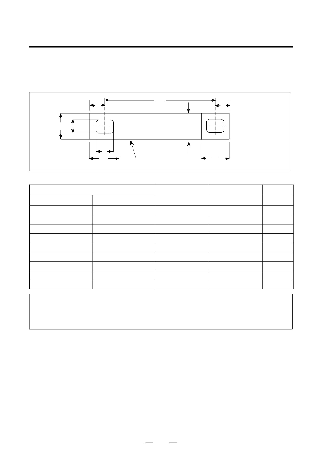
– Specifications of short bars for connecting modules placed close to each other
(1) Specifications of short bars for connecting other than 300-mm-wide
modules
L
10
10
ÇÇÇÇÇÇÇÇÇÇÇ
Material: Copper
14
8
ÇÇÇÇÇÇÇÇÇÇÇ
Thickness: t
ÇÇÇÇÇÇÇÇÇÇÇ
ÇÇÇÇÇÇÇÇÇÇÇ
11
MAX15
22
22
Insulating coating
Table.9.2.1 (d) Short Bar K2 Specifications
Module location
Cross-sec-
Short bar length L
Short bar thickness t
tion area
Module on the left
Module on the right
(Note)
Unit of 150mm wide
Unit of 150mm wide
124mm
1.5mm
21mm2
Unit of 150mm wide
Unit of 90mm wide
85mm
1.5mm
21mm2
Unit of 150mm wide
Unit of 60mm wide
81mm
1.0mm
14mm2
Unit of 90mm wide
Unit of 150mm wide
129mm
1.5mm
21mm2
Unit of 90mm wide
Unit of 90mm wide
90mm
1.0mm
14mm2
Unit of 90mm wide
Unit of 60mm wide
85mm
1.0mm
14mm2
Unit of 60mm wide
Unit of 150mm wide
103mm
1.0mm
14mm2
Unit of 60mm wide
Unit of 90mm wide
64mm
1.0mm
14mm2
Unit of 60mm wide
Unit of 60mm wide
60mm
1.0mm
14mm2
NOTE
Modules need not necessarily be connected with a short bar (copper plate). If you connect
them with a power cable, however, the cable may not be thinner than indicated below and must
be insulated with heat-resistant polyvinyl.
223
9. CONNECTION
B-65162E/03
(2) Specifications of short bars for connecting 300-mm-wide modules
The following table lists the specifications of short bar K2, used for
connecting a
300-mm-wide module to another 300-mm-wide
module or a 150-, 90-, or 60-mm-wide module
Table.9.2.1 (e) Short Bar K2 Specifications
Applicable terminal-to-terminal distance
Module on the left
Module on the right
Outline drawing
(Note)
143 to 151mm
300mm wide PSM
300mm wide SPM
Fig. 9.2.1 (a)
184.5mm
300mm wide PSM
150mm wide
Fig. 9.2.1 (b)
141.5 to 145.5mm
300mm wide PSM
90 or 60mm wide
Fig. 9.2.1 (c)
307.5mm
300mm wide SPM
150mm wide
Fig. 9.2.1 (d)
264.5 to 268.5mm
300mm wide SPM
90 or 60mm wide
Fig. 9.2.1 (e)
122.5mm
150mm wide PSM
300mm wide SPM
Fig. 9.2.1 (f)
NOTE
Place a 300-mm-wide module 20 mm apart from a 150-, 90-, or 60-mm-wide module.
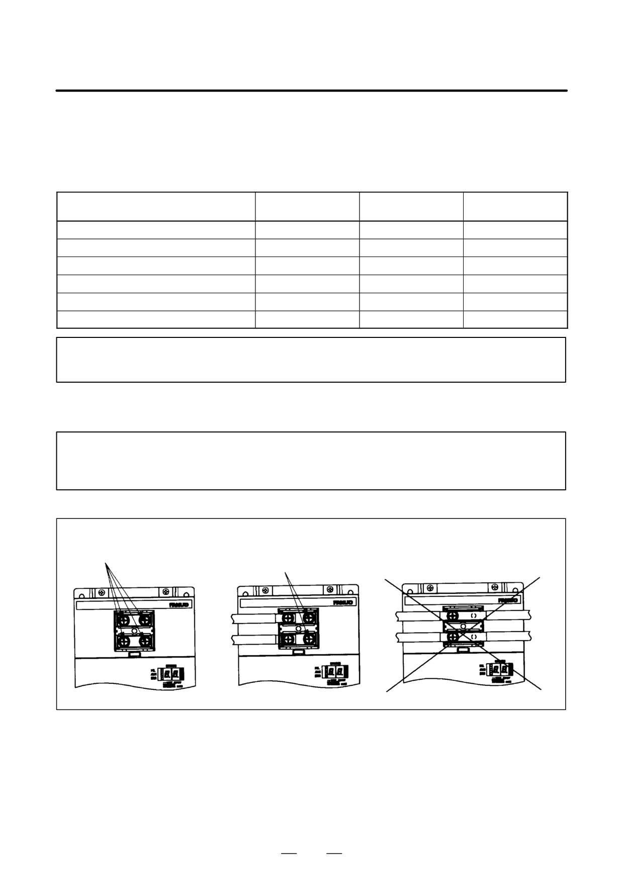
- Cautions on connecting a 150-mm-wide module
NOTE
The terminal board (TB1) on the 150-mm-wide module has four terminal screws. Tighten all
these screws securely.
It is not allowed to make con-
Tighten all terminal screws se-
nections without using screws
Tighten the four terminal
curely, even if neither a short
as shown below. Design a short
screws securely.
bar nor cable is connected.
bar so that four screws can be
tightened.
224
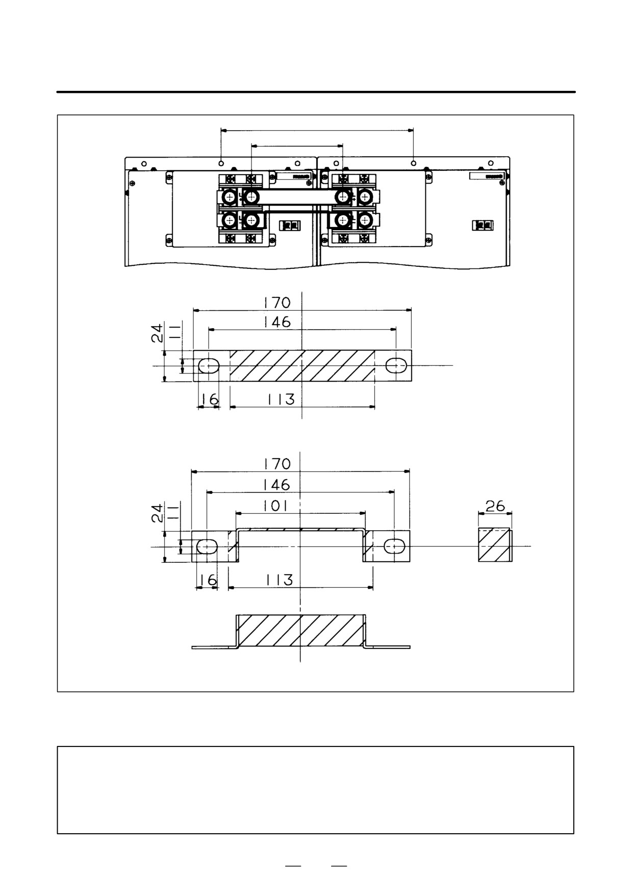
B-65162E/03
9.CONNECTION
Mounting pitch 304
Terminal-to-terminal pitch 147
Short bar 1
Short bar 2
300mm wide PSM
300mm wide SPM
Short bar 1
Short bar 2
Material: C1100 2t
Fig.9.2.1 (a) Short Bar Outline Drawing (for Use Between a 300-mm-Wide PSM and SPM)
Ordering information: A06B-6078-K823
NOTE
If the user prepares a short bar:
- Plate the short bar to protect it against corrosion.
- Insulate the short bar portions indicated by hatching.
- Keep the thickness of the insulation within 1 mm.
225
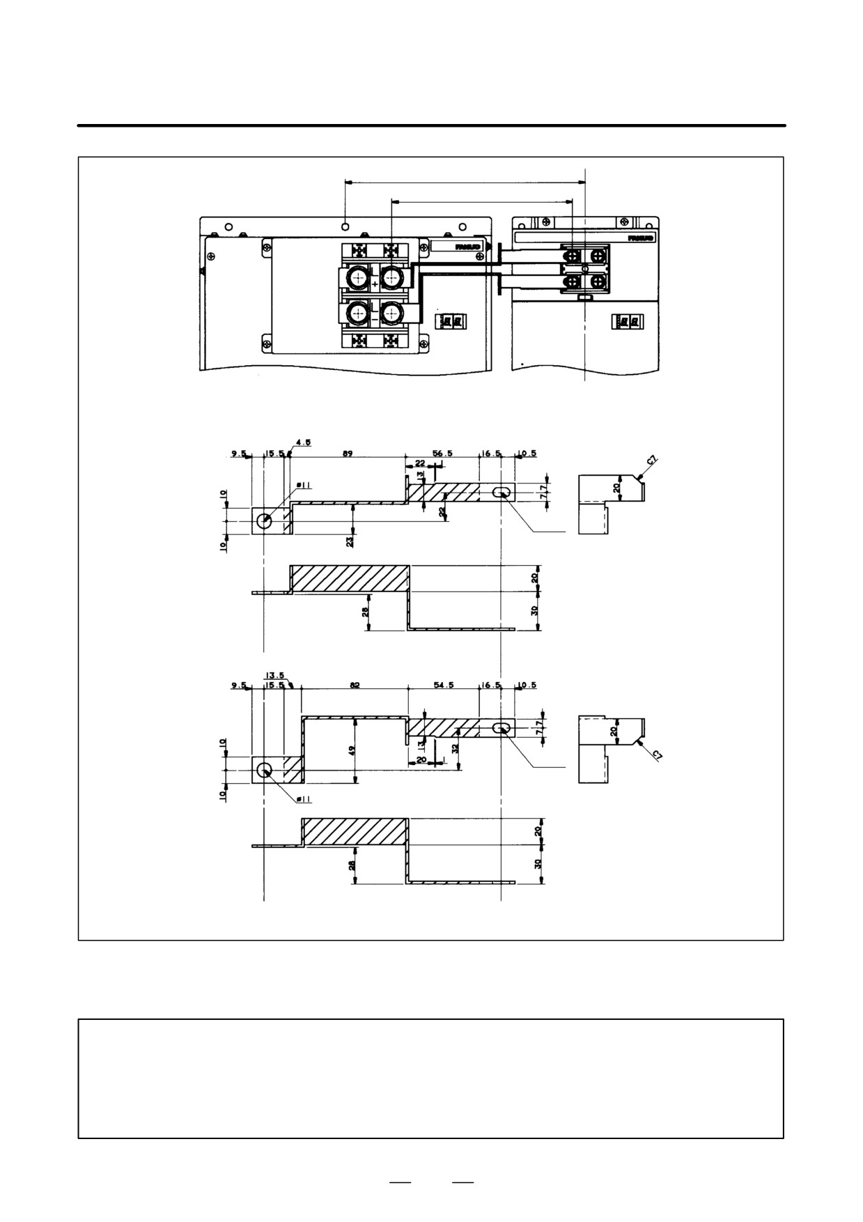
9. CONNECTION
B-65162E/03
Mounting pitch 245
Terminal-to-terminal pitch 184.5
Short bar 1
Short bar 2
300-mm-wide PSM
150-mm-wide module
7
13
oblong hole
Short bar 1
7
13
oblong hole
Short bar 2
Material: C1100 2t
Fig.9.2.1 (b) Short Bar Outline Drawing (for Use Between a 300-mm-Wide PSM and 150-mm-Wide
Module) Ordering information: A06B-6078-K826
NOTE
If the user prepares a short bar:
- Plate the short bar to protect it against corrosion.
- Insulate the short bar portions indicated by hatching.
- Keep the thickness of the insulation within 1 mm.
226
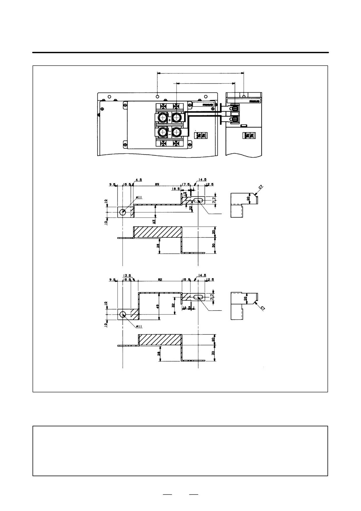
B-65162E/03
9.CONNECTION
Mounting pitch
215 (90 mm wide)
200 (60 mm wide)
Terminal-to-
145.5 (90 mm wide)
terminal pitch
141.5 (60 mm wide)
Short bar 1
Short bar 2
300-mm-wide PSM
90- or 60-mm-wide
module
7
17
oblong hole
Short bar 1
7
17
oblong hole
Short bar 2
Material: C1100 2t
Fig.9.2.1 (c) Short Bar Outline Drawing (for Use Between a 300-mm-Wide PSM and 90- or
60-mm-Wide Module) Ordering information: A06B-6078-K827
NOTE
If the user prepares a short bar:
- Plate the short bar to protect it against corrosion.
- Insulate the short bar portions indicated by hatching.
- Keep the thickness of the insulation within 1 mm.
227
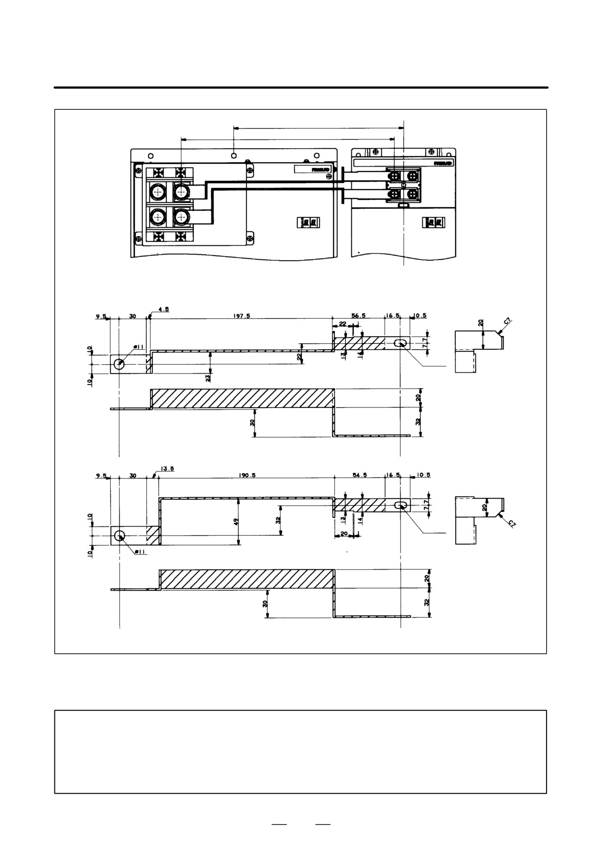
9. CONNECTION
B-65162E/03
Mounting pitch 245
Terminal-to-terminal pitch 307.5
Short bar 1
Short bar 2
300-mm-wide SPM
150-mm-wide module
7
13
oblong hole
Short bar 1
7
13
oblong hole
Short bar 2
Material: C1100 2t
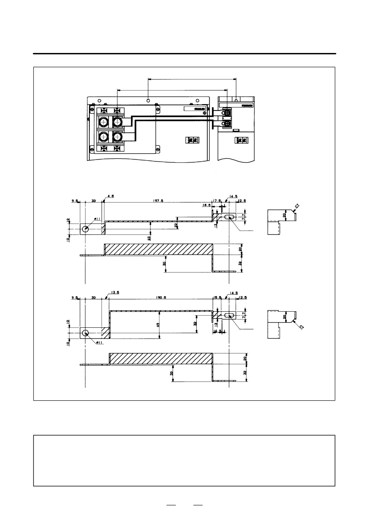
Fig.9.2.1 (d) Short Bar Outline Drawing (for Use Between 300-mm-Wide SPM and 150-mm-Wide
Module) Ordering information: A06B-6078-K828
NOTE
If the user prepares a short bar:
- Plate the short bar to protect it against corrosion.
- Insulate the short bar portions indicated by hatching.
- Keep the thickness of the insulation within 1 mm.
228
B-65162E/03
9.CONNECTION
Mounting pitch
215 (90 mm wide)
200 (60 mm wide)
Terminal-to-
268.5 (90 mm wide)
terminal pitch
264.5 (60 mm wide)
Short bar 1
Short bar 2
300-mm-wide SPM
90- or 60-mm-wide
module
7
17
oblong hole
Short bar 1
7
17
oblong hole
Short bar 2
Material: C1100 2t
Fig.9.2.1 (e) Short Bar Outline Drawing (for Use Between 300-mm-Wide SPM and 90- or 60-mm
Wide Module) Ordering information: A06B-6078-K829
NOTE
If the user prepares a short bar:
- Plate the short bar to protect it against corrosion.
- Insulate the short bar portions indicated by hatching.
- Keep the thickness of the insulation within 1 mm.
229
9. CONNECTION
B-65162E/03
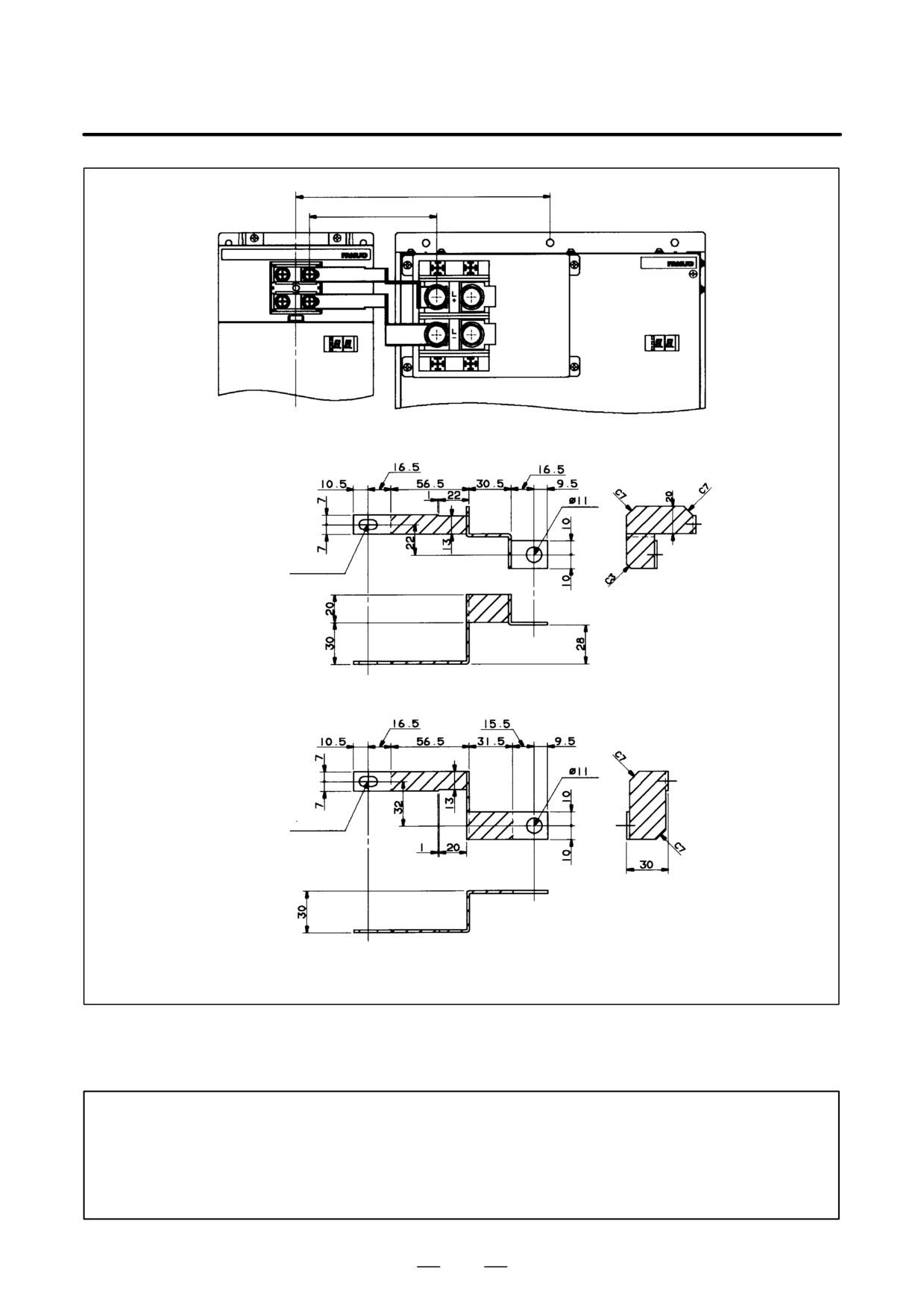
Mounting pitch 245
Terminal-to-terminal pitch 122.5
Short bar 1
Short bar 2
150-mm-wide module
300-mm-wide SPM
7
13
oblong hole
Short bar 1
7
13
oblong hole
Short bar 2
Material: C1100 2t
Fig.9.2.1 (f) Short Bar Outline Drawing (for Use Between 150-mm-Wide PSM and 300-mm-Wide
SPM) Ordering information: A06B-6078-K830
NOTE
If the user prepares a short bar:
- Plate the short bar to protect it against corrosion.
- Insulate the short bar portions indicated by hatching.
- Keep the thickness of the insulation within 1 mm.
230
B-65162E/03
9.CONNECTION
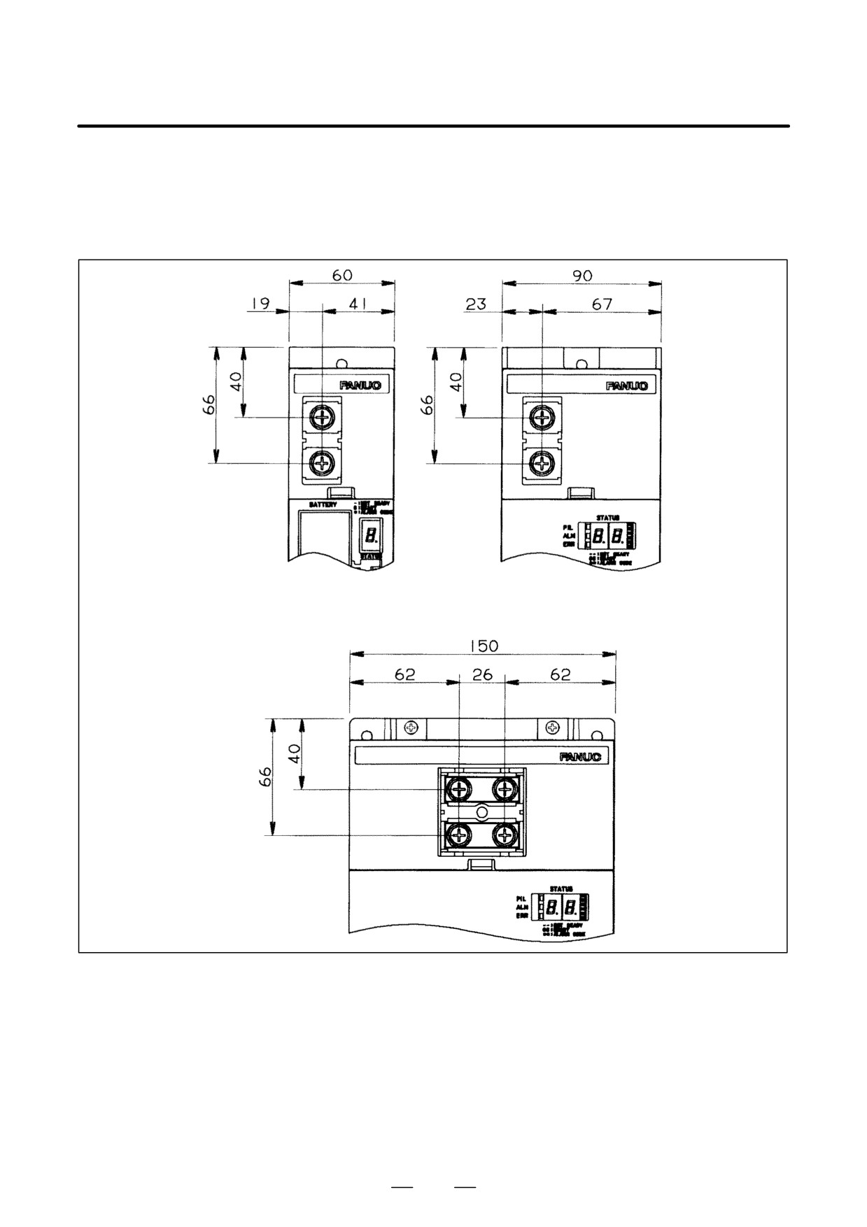
– Location of terminal board TB1 on each module
Figures 9.2.1 (g) and (h) show the location of terminal board TB1 on each
module. If you want to install modules at distances not specified herein,
design short bars by referring to the dimensions shown below.
Fig.9.2.1 (g) Location of Terminal Board TB1 on the 60-, 90-, and 150-mm-Wide Modules
231
9. CONNECTION
B-65162E/03
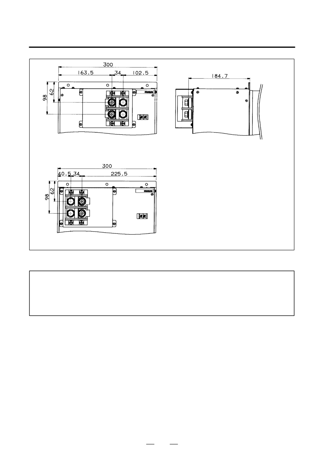
300-mm-wide PSM
Common to 300-mm-wide PSM and SPM
300-mm-wide SPM
Fig.9.2.1 (h) Location of Terminal Board TB1 on the 300-mm-Wide Module
NOTE
1
If a short bar is installed on a terminal indicated by hatching, it is fastened together with a 2t
short bar connected to the inside of the module, so the total height is 186.7 mm.
2
Terminal board TB1 on any of the 60-, 90-, or 150-mm modules is 156.6 mm high.
4.
300-mm-wide SPM
232
B-65162E/03
9.CONNECTION
– FANUC Short Bar Specifications
(1) Specifications of short bars for connecting other than 300mm wide
modules
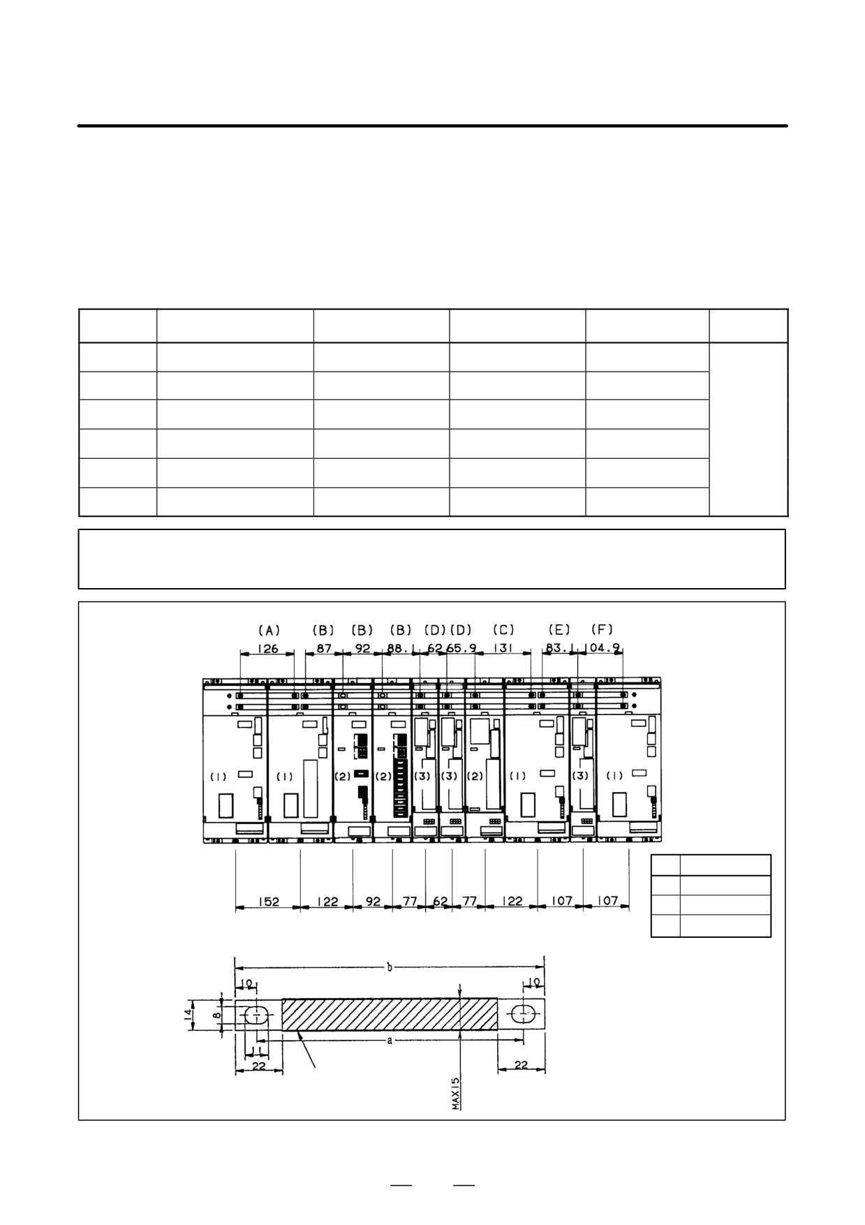
The short bars listed in Tables 9.2.1 (f) and (i) can be used to install
modules placed 2 mm apart from each another.
Table.9.2.1 (f) Short Bar Specifications
Symbol
Ordering information
Dimension of part a
Dimension of part b
Usable range
Thickness
(A)
A06B-6078-K800
124mm
144mm
120 to 128mm
(B)
A06B-6078-K801
90mm
110mm
86 to 94mm
(C)
A06B-6078-K802
131mm
151mm
127 to 135mm
1.5mm
(D)
A06B-6078-K803
64mm
84mm
60 to 68mm
(E)
A06B-6078-K804
85mm
105mm
81 to 89mm
(F)
A06B-6078-K805
102mm
122mm
98 to 106mm
NOTE
Short bars are ordered in pairs.
Module width
1
150mm
2
90mm
3
60mm
Insulating tube
(heat-shrinkable tube)
INSULATOR
Fig.9.2.1 (i) Short Bar Outline Drawing
233

9. CONNECTION
B-65162E/03
(2) Specifications of short bars for connecting 300-mm-wide modules
The short bars listed in Table 9.2.1 (g) and shown in Figures 9.2.1 (a)
to (f) can be used to connect modules placed 20 mm (or 2 mm between
a 300-mm-wide PSM and 300-mm SPM) apart from each other.
Table.9.2.1 (g) Short Bar Specifications
Symbol
Ordering information
Module on the left
Module on the right
Outline drawing
(G)
A06B-6078-K823
300mm wide PSM
300mm wide SPM
Fig. 9.2.1 (a)
(H)
A06B-6078-K826
300mm wide PSM
150mm wide
Fig. 9.2.1 (b)
(I)
A06B-6078-K827
300mm wide PSM
90 or 60 mm wide
Fig. 9.2.1 (c)
(J)
A06B-6078-K828
300mm wide SPM
150mm wide
Fig. 9.2.1 (d)
(K)
A06B-6078-K829
300mm wide SPM
90 or 60 mm wide
Fig. 9.2.1 (e)
(L)
A06B-6078-K830
150mm wide PSM
300mm wide SPM
Fig. 9.2.1 (f)
NOTE
Short bars are ordered in pairs.
(3) Detailed description of the connection of cable K3
Cable K3 is used to supply control power to the power supply module.
Note that if the PSMR is combined with the SPM-11 (with a fan adapter),
the connection will differ from that explained below.
CX1A
PSM
PSMR
(3)
200S
S
(2)
Control power
200V, single-phase
200R
R
(1)
350/X
Cable specification: Two-conductor polyvinyl heavy-duty power cable
(JIS C3312), conductor size of 1.25 mm2 (50/0.18),
PVC sheath 9.6 mm in diameter
Connector specification: AMP connector with receptacle housing
1-178128-3 and receptacle contact 1-175218-2
NOTE
Always connect cable K3 to the CX1A. If it is connected to the CX1B, fuses inside the unit may
blow.
234
B-65162E/03
9.CONNECTION
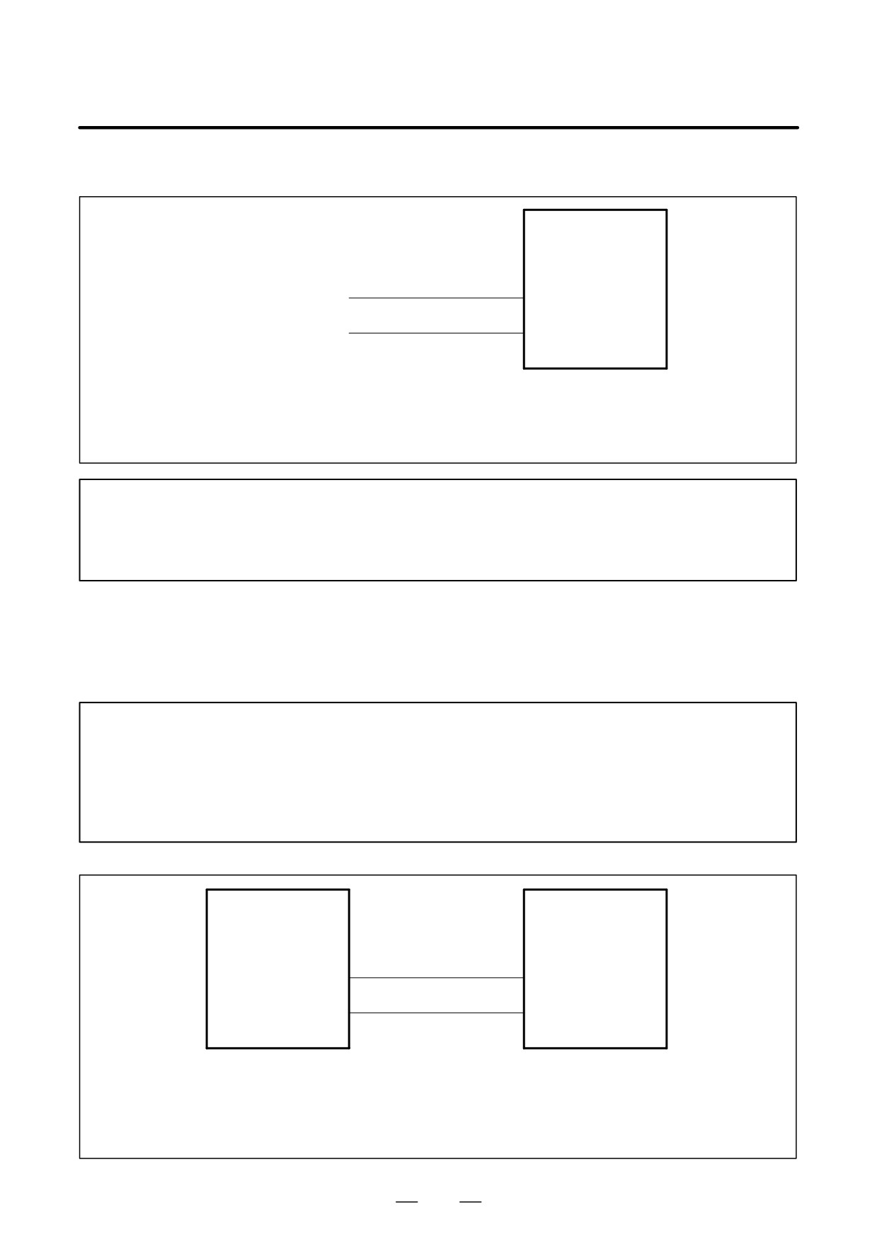
– Cable K3 for combining the PSMR and the SPM-11 (with a fan adapter)
CX1A
SPM
-11
(3)
200S
Control power
S
(2)
200 VAC,
200R
50/60 Hz single-phase R
(1)
350/X
Cable specification: Two-conductor polyvinyl heavy-duty power cable (JIS C3312),
conductor size of 1.25 mm2 (50/0.18), PVC sheath 9.6 mm in diameter
Connector specification: AMP connector with receptacle housing 1-178128-3 and
receptacle contact 1-175218-2
NOTE
If the PSMR is combined with the SPM-11 (with a fan adapter), the position at which cable K3 is
connected differs from other combinations. See the connection diagram under ”Power supply
module (PSMR); connected with the SPM-11 (with a fan adapter)” in Section 9.2.1 for details.
(4) Detailed description of the connection of cable K4
Cable K4 is used to supply power to the cooling fan of a module. Use this
cable to connect the power supply module to a spindle amplifier module
or servo amplifier module having a built-in cooling fan (see below).
Modules to be connected using cable K4
SPM-11 (required only when TYPE 3 or a fan adapter is used)
SPM-15 to SPM-30
SPM-11HV (required only when a fan adapter is used)
SPM-15HV to SPM-45HV
SVM1-240 and SVM1-360
PSM
CX1B
CX1A
SPM
(3)
(3)
200S
(2)
(2)
200R
(1)
(1)
350/X
350/X
Cable specification: Two-conductor polyvinyl heavy-duty power cable
(JIS C3312), conductor size of 1.25 mm2 (50/0.18),
PVC sheath 9.6 mm in diameter
Connector specification: AMP connector with receptacle housing 1-178128-3 and
receptacle contact 1-175218-2
235
9. CONNECTION
B-65162E/03
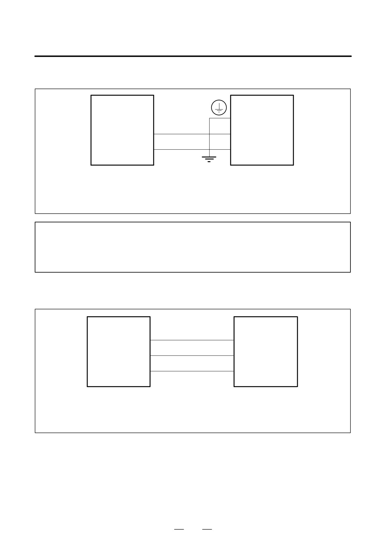
– Combination of the PSMR and the SPM-11 (with a fan adapter)
PSM-11
CX1B
CX1A
PSMR
(3)
(3)
200S
(2)
(2)
200R
(1)
(1)
350/X
350/X
Cable specification: Two-conductor polyvinyl heavy-duty power cable
(JIS C3312), conductor size of 1.25 mm2 (50/0.18),
PVC sheath 9.6 mm in diameter
Connector specification: AMP connector with receptacle housing 1-178128-3 and
receptacle contact 1-175218-2
NOTE
If the PSMR is combined with the SPM-11 (with a fan adapter), the position at which to connect
cable K4 differs from the connection for other combinations. See the connection diagram under
”Power supply module (PSMR); connected with the SPM-11 (with a fan adapter)” in Section
9.2.1 for details.
(5) Detailed description of the connection of cable K5
Cable K5 is used to connect 24 VDC control power to each module.
PSM
CX2B
CX2A
SVM
SPM
ESP
SPMC
(3)
(3)
0V
(2)
(2)
+24V
(1)
(1)
250/X
250/X
Cable specification: Three-conductor polyvinyl heavy-duty power cable (JIS C3312),
conductor size of 1.25 mm2 (50/0.18),
PVC sheath 10.5 mm in diameter
Connector specification: AMP connector with receptacle housing 1-178288-3 and
receptacle contact 1-175218-2
236
B-65162E/03
9.CONNECTION
(6)
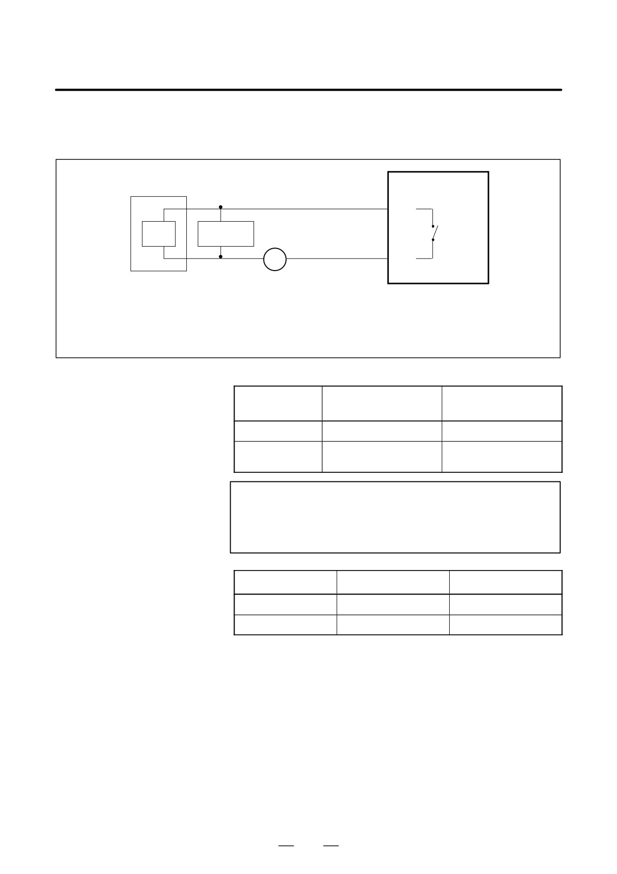
Detailed description of the connection of cable K6
Cable K6 is used to control the magnetic contactor if it is installed outside
the unit.
CX3
PSM
MCC
MCCOFF3
(3)
Internal
Coil
Spark killer
(2)
contact
MCCOFF4
(1)
~
350/Y
External power supply
(must match the coil voltage of the user’s equipment)
Cable specification: Two-conductor polyvinyl heavy-duty power cable (JIS C3312),
conductor size of 1.25 mm2 (50/0.18), PVC sheath 9.6 mm in diameter
Connector specification: AMP connector with receptacle housing 2-178128-3 and
receptacle contact 1-175218-2
Internal-contact specification:
Resistive load
Inductive load
Symbol
(cos φ=1)
(cosφ=0.4, L/R=7msec)
Rated load
250VAC, 5A / 30VDC, 5A
250VAC, 2A / 30VDC, 2A
Maximum contact
5A
5A
rating
NOTE
Always install a spark killer (CR) that matches the magnetic
contactor to protect the internal contacts. The following
table lists the recommended capacitances and resistances.
Coil voltage
C
R
24 VDC
0.22µF
22Ω
100 VAC to 240 VAC
0.1µF
220Ω
237
9. CONNECTION
B-65162E/03
(7) Detailed description of the connection of cable K7
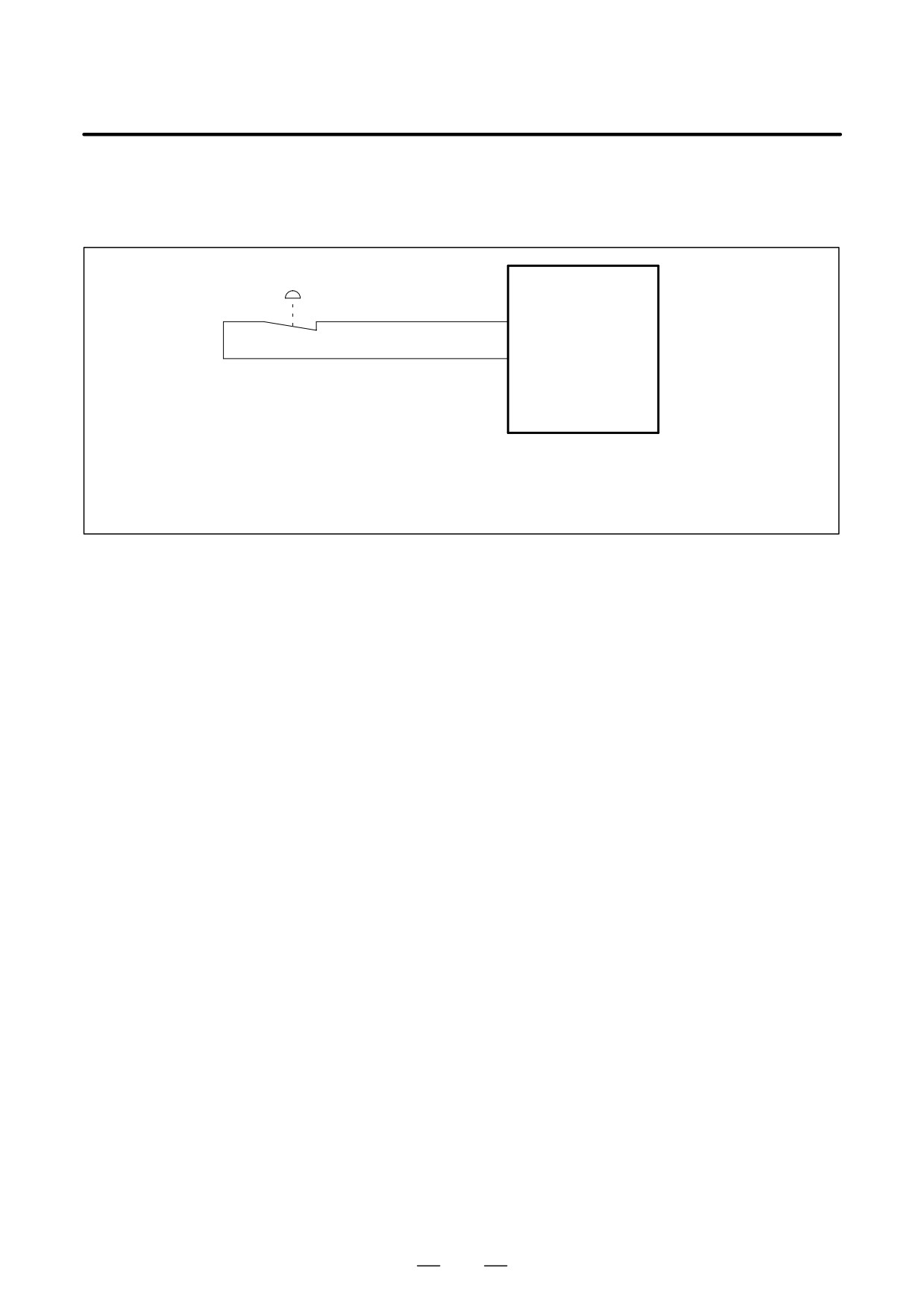
Cable K7 is used to supply an emergency stop signal to the power supply
module.
Emergency stop contact
CX4
PSM
+24V
(3)
ESP
(2)
(1)
350/X
Cable specification: Two-conductor polyvinyl heavy-duty power cable (JIS C3312),
conductor size of 1.25 mm2 (50/0.18), PVC sheath 9.6 mm in diameter
Connector specification: AMP connector with receptacle housing 1-178128-3 and
receptacle contact 1-175218-2
238
B-65162E/03
9.CONNECTION
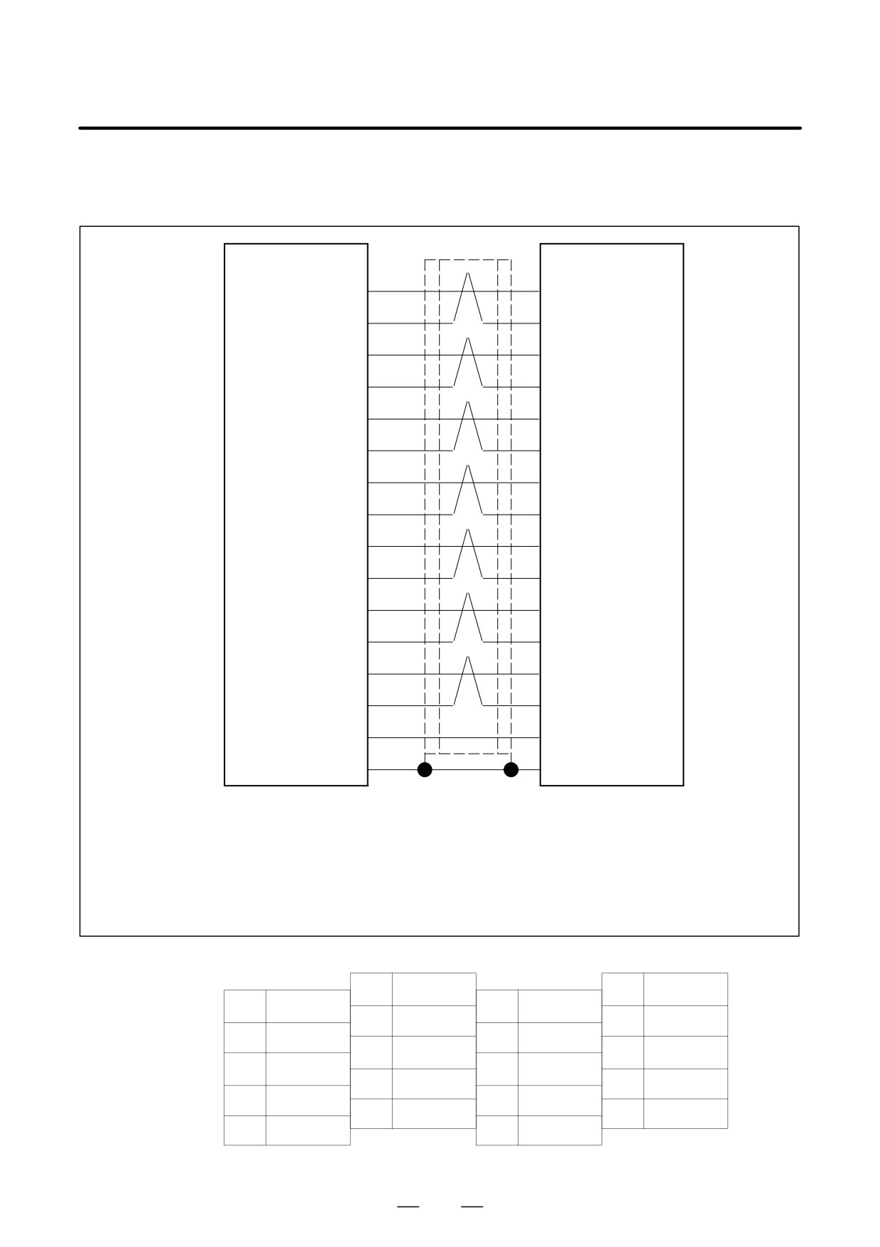
(8) Detailed description of the connection of cable K8
Cable K8 is used to exchange interface signals between modules.
PSM
JX1B
JX1A
SVM
IALM
SPM
(5)
(5)
SPMC
0V
(6)
(6)
MCCOFF
(7)
(7)
0V
(8)
(8)
*CRDY
(9)
(9)
0V
(10)
(10)
ALM1
(11)
(11)
0V
(12)
(12)
ALM2
(13)
(13)
0V
(14)
(14)
ALM4
(15)
(15)
0V
(16)
(16)
ALM8
(17)
(17)
0V
(18)
(18)
CALM
(19)
(19)
SS
(20)
(20)
Example of usable connector
Example of usable connector
(HONDA)
(HONDA)
Connector PCR-E20FA
Connector PCR-E20FA
Housing PCR-V20LA
Housing PCR-V20LA
Cable specification: 0.09 mm2 twisted pair with common shielded
Recommended cable (wire only): A66L-0001-0284#10P
See Appendix C for details.
Pin arrangement of connectors JX1B and JX1A
10
0V
20
SS
9
*CRDY
19
CALM
8
0V
18
0V
7
MCCOFF
17
ALM8
6
0V
16
0V
5
IALM
15
ALM4
4
14
0V
3
13
ALM2
2
12
0V
1
11
ALM1
239
9. CONNECTION
B-65162E/03
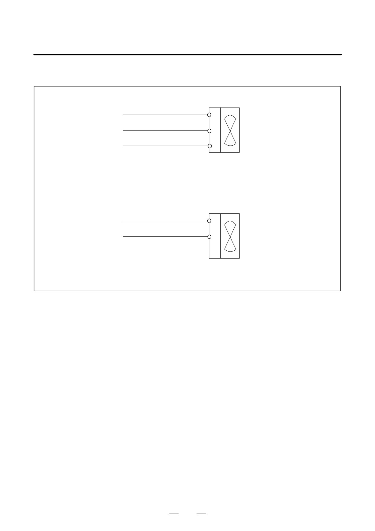
(9) Detailed description of the connection of cable K11
Power for fan motor
200V, three-phase
200R
R
R0
200S
S
S0
Fan motor
200T
T
T0
Cable specification: Use a three-conductor polyvinyl heavy-duty power cable (JIS C3312)
having a conductor size of 2 mm2 or larger.
Fan motor terminal screw: M4
Power for cooling fan (for the PSM-45 and PSM-75HV only)
200V, three-phase
200R
R
R0
200S
S
S0
Fan motor
Cable specification: Two-conductor polyvinyl heavy-duty power cable (JIS C3312),
conductor size of 1.25 mm2 (50/0.18), PVC sheath 9.6 mm in diameter
240
B-65162E/03
9.CONNECTION
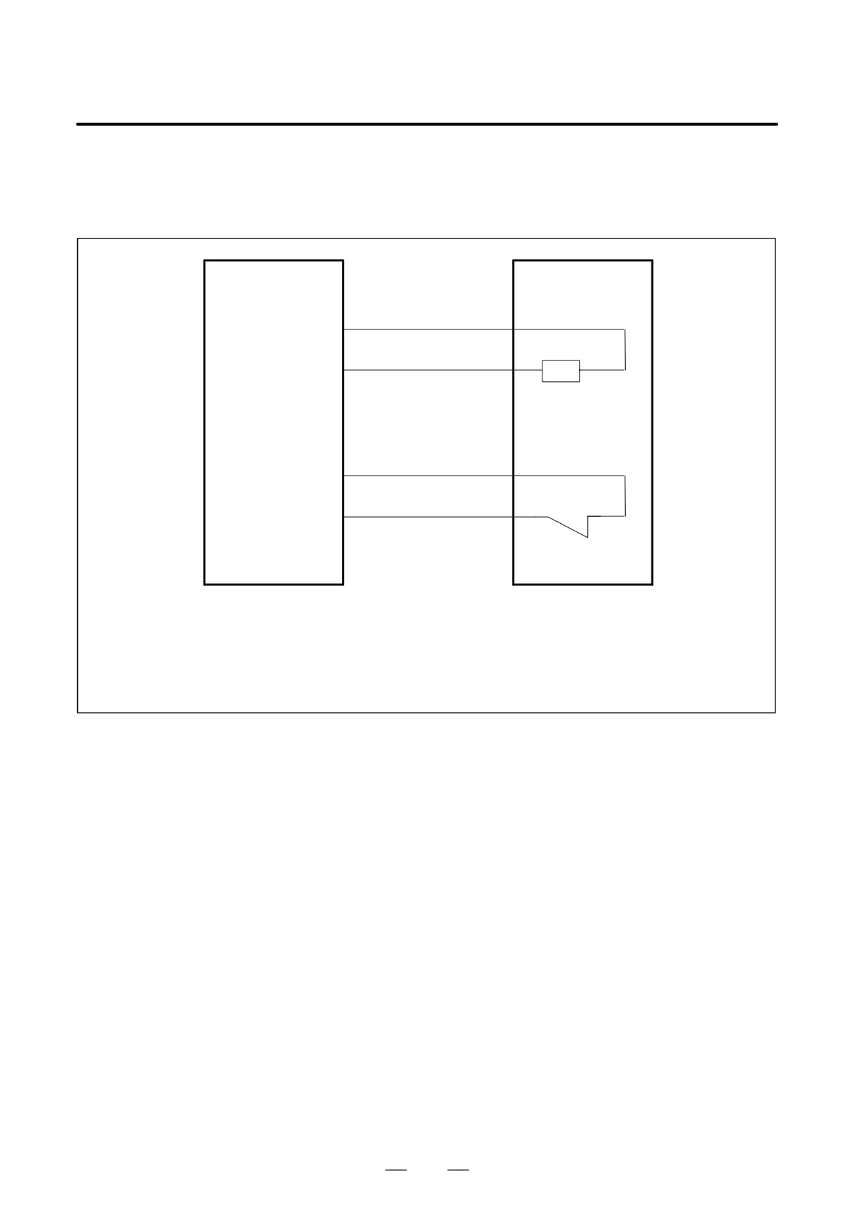
(10) Detailed description of the connection of cables K41 (for regenerative discharge resistance),
K42 (for thermostat), and K43 (for fan motor)
(a) A06B-6089-H510 and A06B-6089-H500
Regenerative
PSMR
discharge unit
TB2
K41
RE1
(1)
(RE1)
Resistance
(2) of 16Ω
RE2
(RE2)
Regenerative
discharge resistance
K42
TH1
(3)
(TH1)
(4) Thermostat
TH2
(TH2)
b contact
Terminal screw M4
Terminal screw M4
Cable specification
K41 : Two-conductor polyvinyl heavy-duty power cable,
conductor size of 2.0 mm2 (37/0.26),
PVC sheath 10.5 mm in diameter
K42 : Two-conductor polyvinyl heavy-duty power cable,
conductor size of 0.75 mm2 (30/0.18),
PVC sheath 8.8 mm in diameter
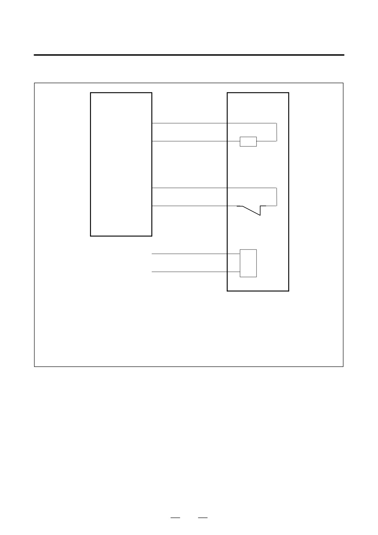
241
9. CONNECTION
B-65162E/03
(b) A06B-6089-H711 to -H713
Regenerative
PSMR
discharge unit
TB2
T3
K41
RE1
(1)
(RE1)
(2)
RE2
(RE2)
Regenerative
discharge resistance
K42
TH1
(3)
(TH1)
(4) Thermostat
TH2
(TH2)
b-contact
Terminal screw M4
K43
200R
(5)
Control power
200V, single-phase
Fan motor
(6)
200S
Terminal screw M4
Cable specification
K41 :
Two-conductor polyvinyl heavy-duty power cable (JIS C3312),
conductor size of 2.0 mm2 (37/0.26),
PVC sheath 10.5 mm in diameter
K42 :
Two-conductor polyvinyl heavy-duty power cable (JIS C3312),
conductor size of 0.75 mm2 (30/0.18),
PVC sheath 8.8 mm in diameter
K43 :
Two-conductor polyvinyl heavy-duty power cable (JIS C3312),
conductor size of 2.0 mm2 (37/0.28),
PVC sheath 10.5 mm in diameter
242