FANUC SERVO AMPLIFIER a series. DESCRIPTIONS (B-65162E/03) - page 15
B-65162E/03
10. INTERFACE SIGNALS
10.4.11
Frequency Detecting
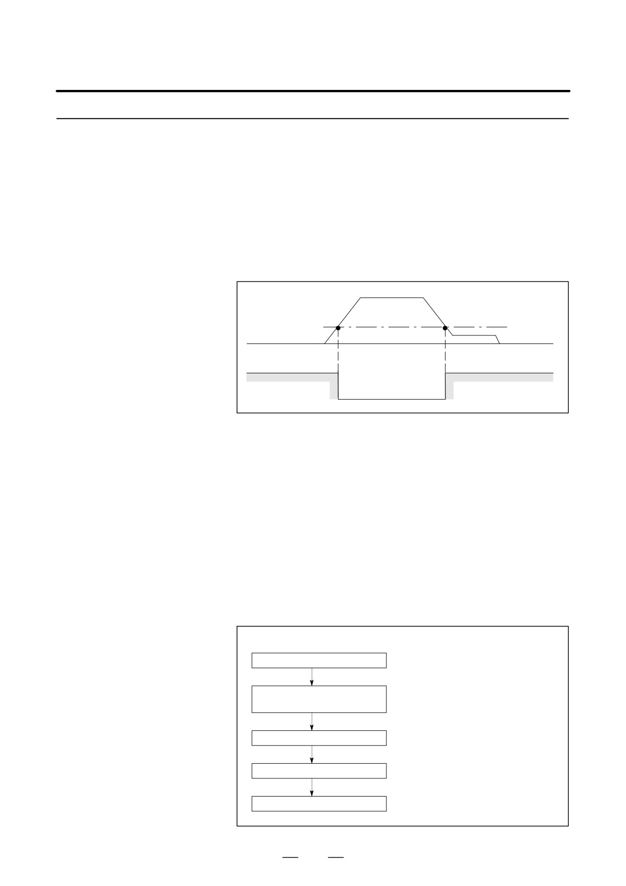
D SDTA = 1 occurs when the frequency is lower than the one which is
set by parameter.
Signal (SDTA)
D This signal is used to detect that the output frequency has become
lower than a certain frequency set such as clutch selectable speed or
gear selectable speed.
D The frequency detecting level can be set by parameter.
D For this signal, SDTA = 1 occurs when the absolute value of the output
frequency is reduced to be lower than the preset detection level,
irrespective of rotation commands (SFRA, SRVA).
Output frequency
Frequency detection level
0min-1
SDTA
1
0
1
Fig.10.4.11 (a) Speed Detection Signal
Reference
D Sequence of the gear
The gear shift in the CNC machine tool is one of the sequence controls.
shift
The electric circuit signal in the sequence is used to move the spindle gear,
which is an important component of the machine. It is then necessary to
check that the spindle motor speed is in low speed to switch the gear
safely.
The following is an example of sequence at gear shift, when the frequency
detection signal (gear selectable signal) was used. This example can be
referred to when designing the magnetics sequencer.
D An example of gear shift sequence using frequency detection
signal
(Sequence)
(Check signal)
Gear shift command
Low speed revolution com-
mand of the spindle motor
Speed check
Frequency detection signal=1
Shifter moves
(or frequency stopped signal=1)
End of gear shift
423
10. INTERFACE SIGNALS
B-65162E/03
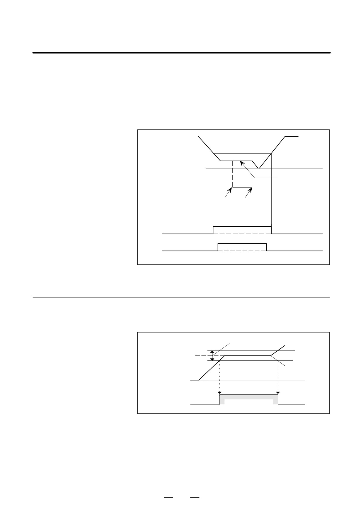
To change the gear safely, it must be checked that the spindle motor speed
is low enough before moving the shifter. If the frequency stop signal is
also applied, the safety can be doubly checked.
Essential reason to confirm the spindle motor speed :
If the shifter moves when the spindle motor is rotating at high speed, the
gear will break.
Gear selectable output
frequency range
Output frequency
0 rpm
Spindle motor
speed at gear shift
(Low speed)
Shifter
End of
moves
gear shift
1
0
0
Frequency detection
1
signal (gear selectable signal)
0
Frequency-stop detect signal
Fig.10.4.11 (b) Frequency Detection Signal
10.4.12
Frequency Arrival
D SARA = 1 occurs when output frequency of the actual spindle motor
module arrives within the range set by the frequency command.
Signal (SARA)
Detection range
Specified
frequency
Output
frequency
0
1
0
SARA
Fig.10.4.12 (a) Frequency Arrival Signal
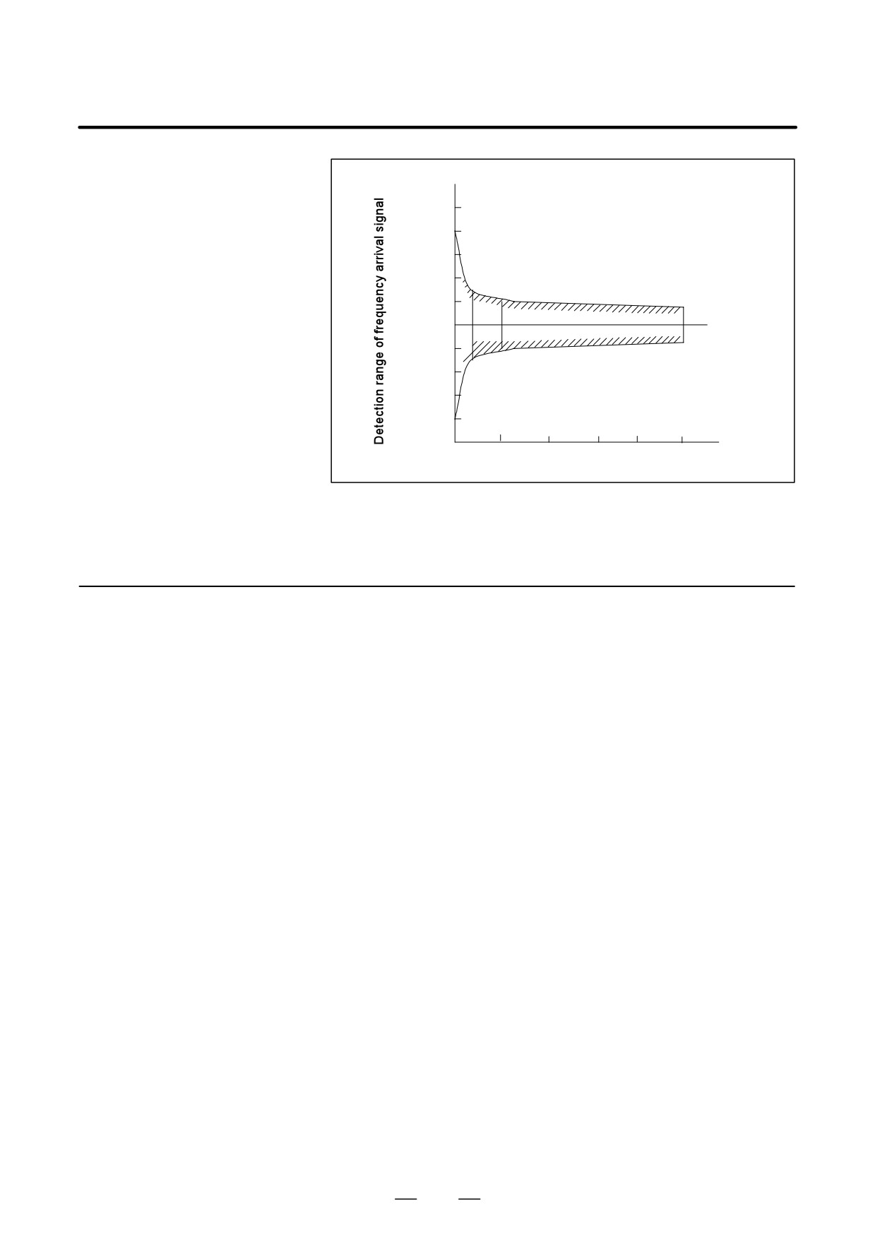
D The setting range is "1 to 100% of the command frequency. However,
when the speed is less than 10% of the maximum frequency, the
detection range becomes wider than the preset range.
D The standard setting at shipment is "15%. However, the detection
range of this frequency arrival signal at low speed widens as shown in
the diagram below.
424
B-65162E/03
10. INTERFACE SIGNALS
200
177% (at 80min-1)
115%
100
85%
23% (at 80min-1)
0
Maximum frequency
Fig.10.4.12 (b) Detection Range of the Speed-Arrival Signal
D If one of these signals, SFRA or SRVA, is not 1, it is not outputted.
10.4.13
D Assume that the maximum output (10 V) of the load meter (LM) is
Load Detection Signal
100%. When the output of the load meter reaches the parameter
(LDTA)
settings (%), load detection signal is set to 1.
D The PMC can reduce the feedrate or stop the feed to prevent the spindle
from stopping when cutting overload is applied to the spindle by using
this signal.
D This signal is not output for 10 seconds (by PRM4082 of series 16)
after the speed command has changed.
425
10. INTERFACE SIGNALS
B-65162E/03
10.4.14
Speed Integral Control
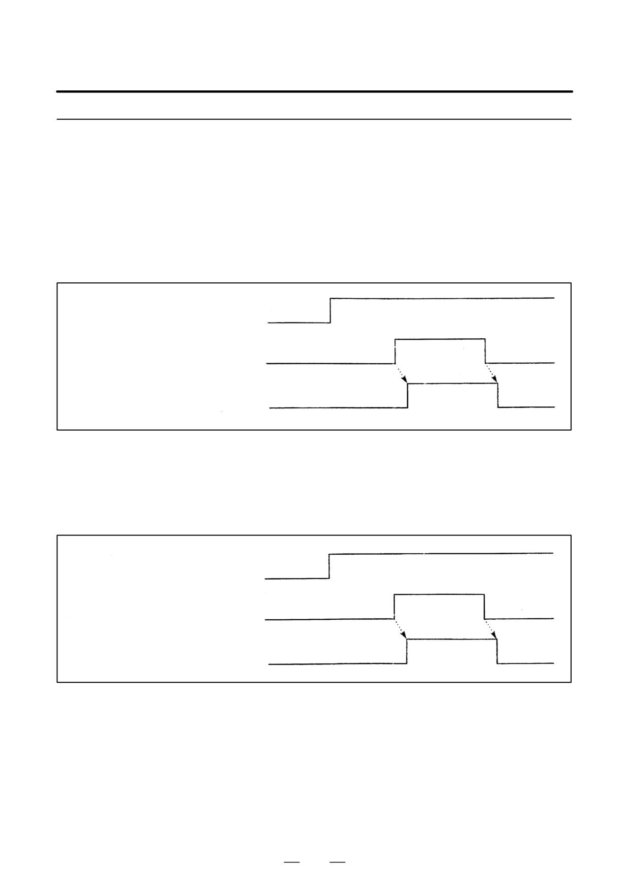
D During spindle position control (such as spindle orientation control),
the spindle may be clamped when a brake is applied. If the spindle is
Signal (INTGA)
clamped with a small displacement remaining, an excessive current
may flow through the motor in order to eliminate the displacement by
performing speed integral control. In this case, this signal can be used
to nullify speed integral control so as to prevent an excessive current
from flowing through the motor.
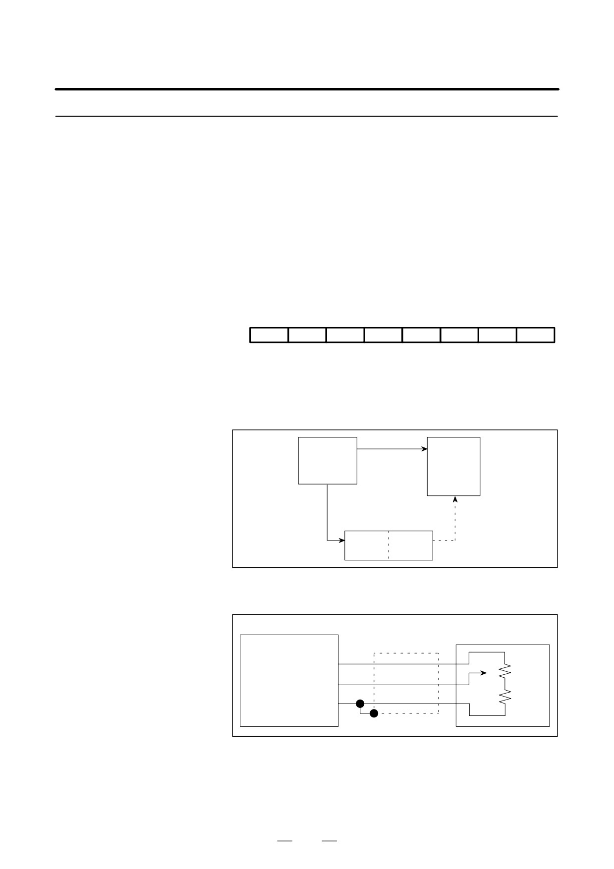
Spindle position control
Spindle clamped
Speed integral control signal INTGA
D If a very small synchronization error occurs between two spindles
when they are used to hold a workpiece in spindle synchronization, an
excessive current may flow through the motor in order to eliminate the
error by performing speed integral control. In this case, this signal can
be used to nullify speed integral control so as to prevent an excessive
current from flowing through the motor.
Workpiece held
Spindle synchronization
by two spindles
Chucks closed
Workpiece held by two spindles (chucks closed)
Speed integral control signal
426
B-65162E/03
10. INTERFACE SIGNALS
10.4.15
Spindle Analog
D
This function allows an analog voltage input to the spindle amplifier
to apply an override to the frequency command.
Override Command
(OVRA)
D
The analog override function is valid only in the normal control mode.
D
The analog override function is valid when this signal is 1.
D
The following parameter sets the upper limit of the analog override.
The input voltage value that corresponds with the frequency of the
upper limit of analog override is 4.5 V across OVR2 and 0V. (An input
more than 4.5 V does not make excess of the maximum frequency).
Even if an overridden frequency command exceeds the value set with
the max. frequency parameter, the frequency is clamped to the
maximum frequency.
(Parameter No.)
#7
#6
#5
#4
#3
#2
#1
#0
FS0
FS15
FS16
ALGOVR
1st Spindle : 6506
3006
4006
2nd Spindle: 6646
3146
ALG OVR =0 : Upper limit 100%
=1 : Upper limit 120%
D
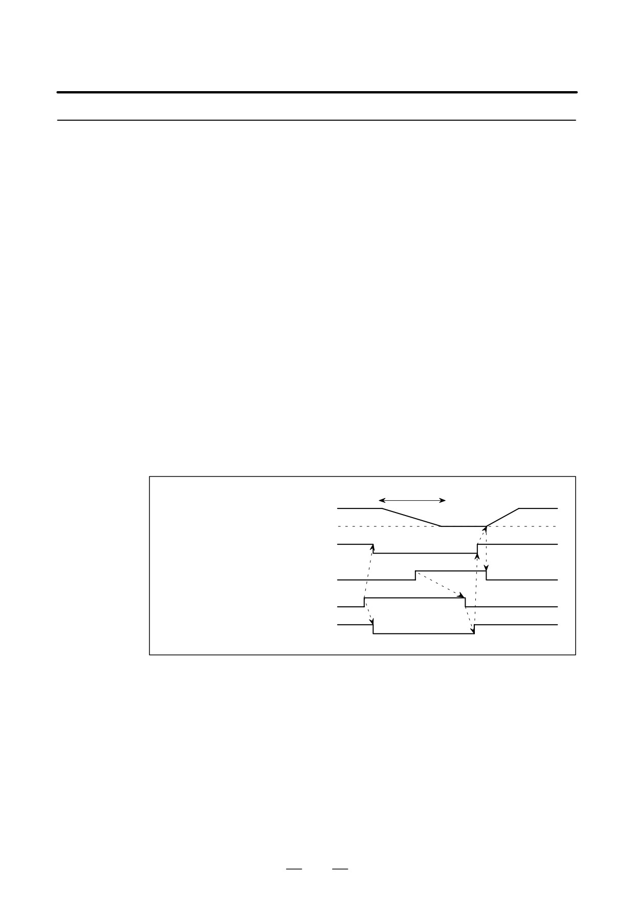
A system configuration in relation with the analog override function
is as follows:
Analog
Machine
Spindle
input
operator’s
OVR1
amplifier
panel
OVR2
module
Override
valid/invalid
OVRA
PMC
CNC
Connection about the analog override input is as follows:
The override unit is 1%.
Machine operator’s
JY1
panel
Spindle amp module
Shield wire
(Nominal voltage) OVR1
VR
(Analog input) OVR2
V1
(0V)
0V
Use the resistor(VR + R1) of 2 kΩ to 10 kΩ .
D When the analog override function valid/invalid switch signal is
switched, or when the override upper limit parameter is switched, the
motor speed may change radically. Therefore switch the signal or
parameter when the spindle is stopped.
427
10. INTERFACE SIGNALS
B-65162E/03
10.4.16
Motor Power Off Signal
D This signal is used to cut the power of the motor when a failure occurs
while the spindle synchronization control or the gear cutting machine
(MPOFA)
is operating. When the power is cut, the motor runs free.
D This signal only cuts the power of the motor.
D Supply the motor with power after enough time has passed to
completely stop the motor.
If the signal is released, the power cannot be restored to the motor
while the motor is operating (SSTA = 0).
D After the power of the motor is cut, all the operation modes(*1) must
be canceled for safety.
After the motor stops (SSTA = 1), set the operation modes again.
When the power is cut during position control, an alarm such as
excessive deviation may occur because position control remains
effective.
(*1) Example of operation modes:
- Forward rotation command (SFRA)
- Reverse rotation command (SRVA)
- Spindle orientation (ORCMA)
- Spindle synchronization control (SPSYC, SPPHS)
- Rigid tap (RGTP, RGTAP
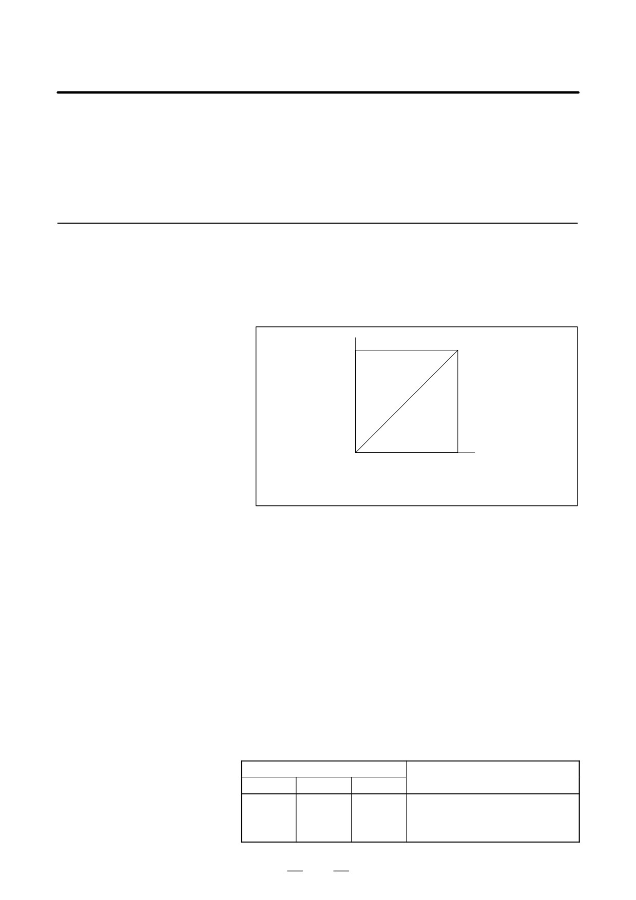
D Example of the sequence
Free run
Output frequency
0 min-1
ON
Motor power
OFF
1
Frequency stop detection
0
signal, SSTA
1
Motor power off signal, MPOFA
0
ON
Operation mode such as SFRA
OFF
D Setting bit 2 of parameter 4009 (series 16) to 1 cuts off the power of
the motor as soon as the AL-24 spindle alarm (serially transmitted data
error) occurs. The motor usually decelerates and stops when the alarm
occurs.
428
B-65162E/03
10. INTERFACE SIGNALS
10.5
SPINDLE AMPLIFIER
OUTPUT SIGNALS
(αC SERIES SPINDLE)
10.5.1
Output Frequency
D
The output frequency of the AC spindle motor can be indicated by
externally connecting a speedmeter.
Display Signal (SM)
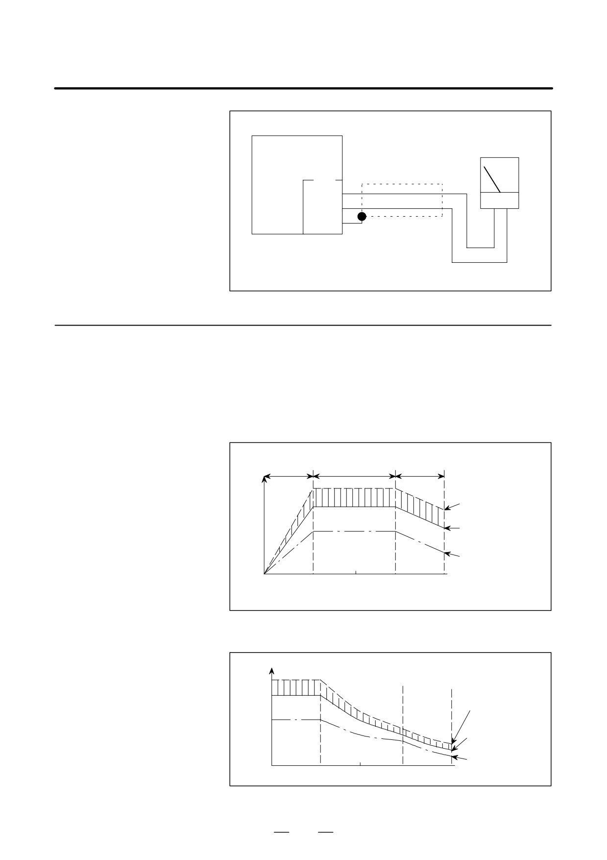
A voltage
(DC) proportional to the rotation speed is output,
(Usable as Load Meter
irrespective of the forward or reverse rotation of the motor. A +10V
Voltage Signal
is output at the maximum frequency.
According to
Parameter Setting)
+10V
Output
voltage
(DC)
0V
0min-1
Max. output frequency
Motor rotation speed
D
Use the following speedmeter
(DC voltmeter)
- One-sided deflection DC voltmeter
- DC voltage 10V full scale
- Internal resistance higher than 10 kΩ
Example)
DC voltmeter LM-80: Kuwano Electrical Manufacturing Co., Ltd.
D For deteils of connection cable and connectors, refer to
9.3.6(3).
D Due to the construction of internal circuit, there exists about
10mV (0.1%) ripple at the output of SM terminal
D This signal can be used for load meter by setting the
parameter (PRM4007#4=1 : series 16). The load meter
outputs +10V when the spindle motor exhibits its maximum
output.
Parameter
Contents
FS0
FS15
FS16
6507#4
3007#4
4007#4
Selects type of data output from SM ter-
6607#4
3147#4
minal
0 : Frequency data
1 : Load meter data
429
10. INTERFACE SIGNALS
B-65162E/03
Frequency meter
Spindle amp module
(or load meter)
Shield
JY1
17
SM
19
0M
20
0V
10.5.2
Load Meter
D When the SM terminal output is used for load meter by parameter the
rated input voltage is applied, the frequency-to-spindle motor output
Voltage (LM) (Either
relation, frequency-to-torque relation and frequency-to-load meter
Speedometer Data or
relation are as shown in Figs. 10.5.2 (a), 10.5.2 (b), and 10.5.2 (c).
Load Meter Data is
D The load meter indicates the load factor, which is the ratio of the load
Selected According to
to the maximum output of the spindle motor.
Parameter Setting)
Constant
Lowered output
Constant output
torque region
power region
power region
P
Maximum output
power of motor
(]30min. rated
output power
120%)
Spindle
motor
30min. rated output
output
power
power
[kW]
Continuous rated
output power
0
(Base
Maximum frequency
(Maximum
frequency)
of constant power
frequency)
region
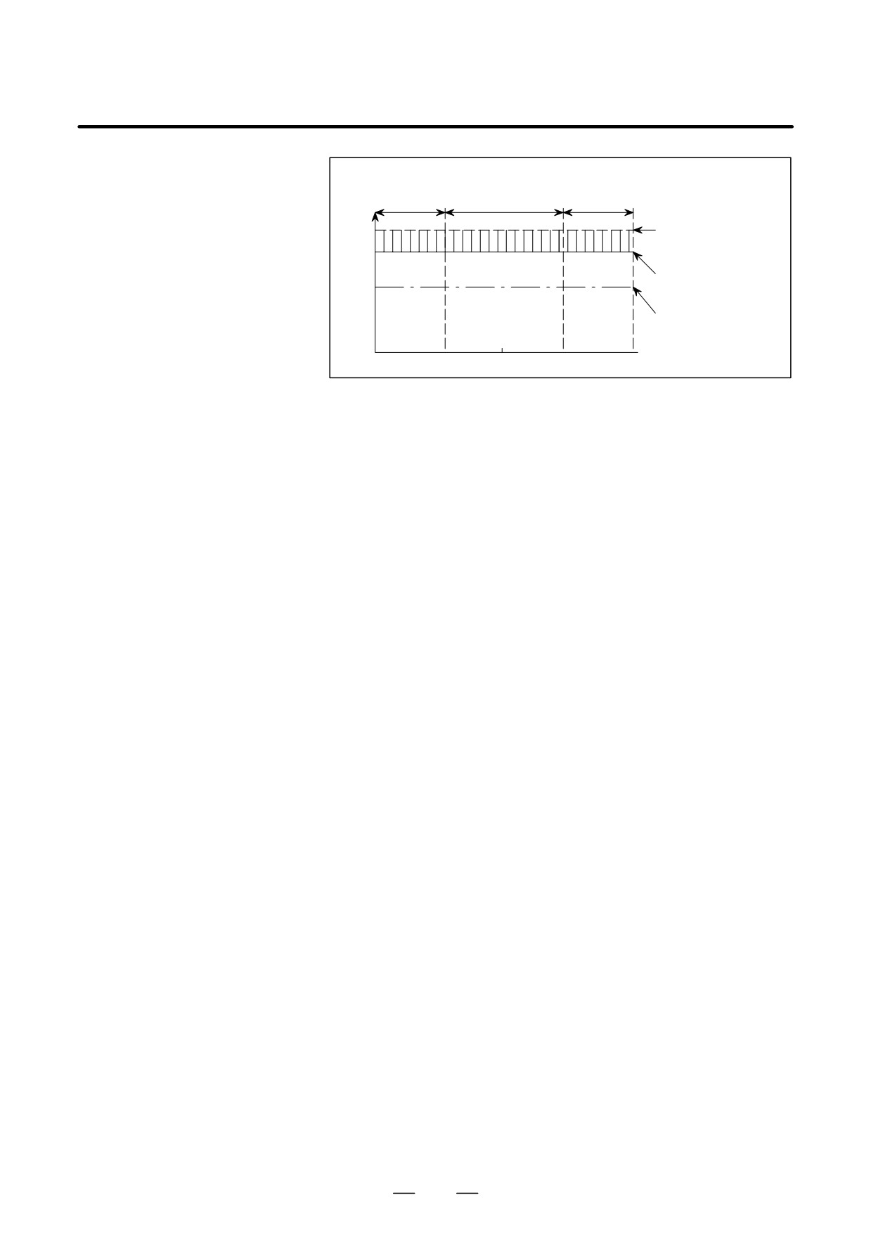
Fig.10.5.2 (a) Spindle Motor Output
T
Maximum torque
of motor
(]30min. rated
Spindle
torque
120%)
motor
torque
30min. rated torque
[kg·m]
Continuous rated
0
torque
Fig.10.5.2 (b) Spindle Motor Torque
430
B-65162E/03
10. INTERFACE SIGNALS
Constant
Constant output
Lowered output
torque region power region
power region
Maximum output
power of motor
10V
(]30min. rated output
8.3V
power
120%)
30min. rated output
Load
power
meter
power
Continuous rated
output power
Fig.10.5.2 (c) Voltage Used for Operating a Load Meter
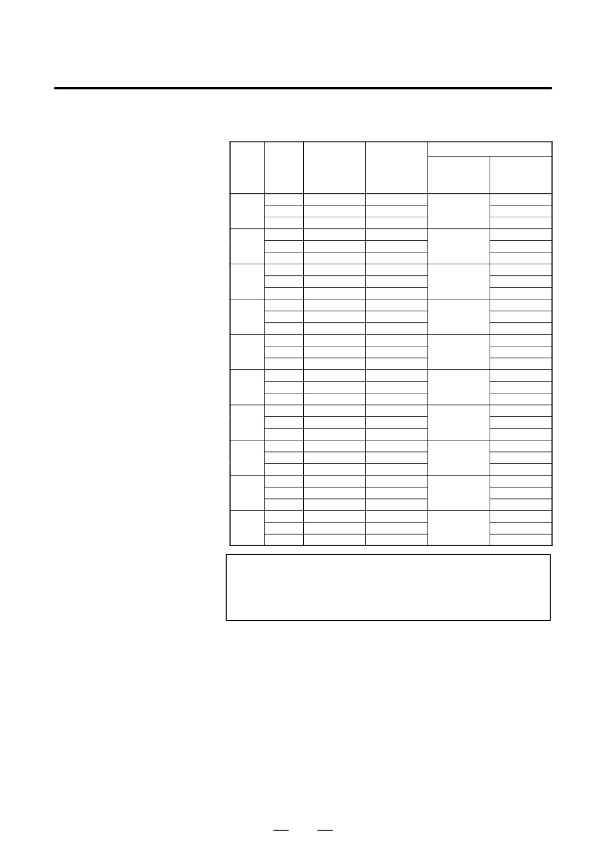
D The relation between each spindle motor output and the indicating
voltage of the load meter is as shown in Table 10.5.2 (a), assuming
that the continuous rated output of the spindle motor is 100%.
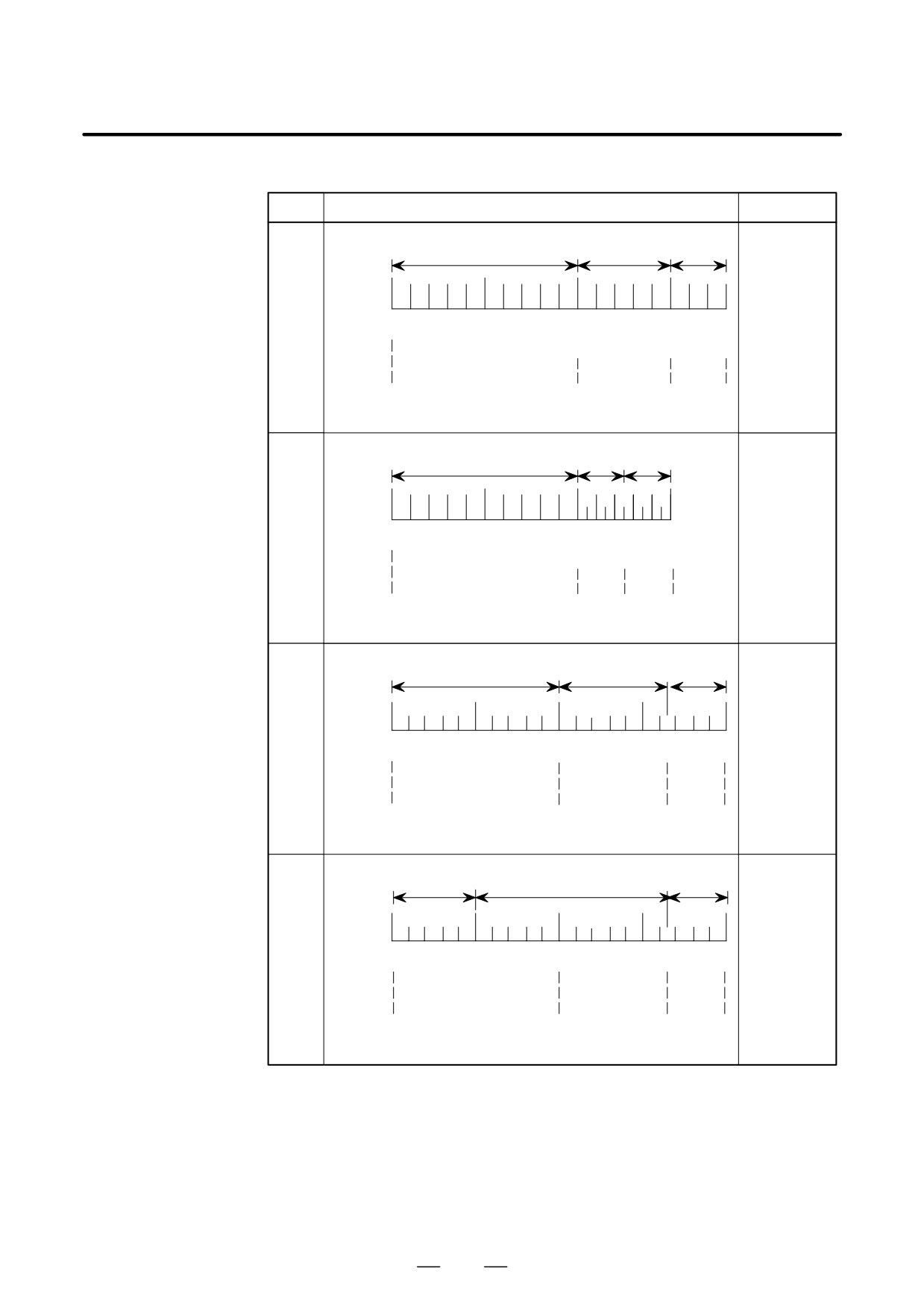
D Three types of indications of the load meter may be considered
approximately from Table 10.5.2 (a). For the indication of the load
meter in this case, refer to examples shown in Table 10.5.2 (b).
D The load meter (DC voltmeter) being used shall satisfy the following
requirements:
D One-side deflection DC voltmeter
D
10 VDC full-scale
D Internal resistance of 10kΩ or higher
Example)
DC voltmeter LM-80 produced by Kuwano Denki
D Use two-conductor shielded cables.
431
10. INTERFACE SIGNALS
B-65162E/03
Table.10.5.2 (a) Relation between each spindle motor output and
indicating voltage of load meter
Example of load meter
Indicating
Ratio asum
Output
voltage of
ing that con-
Type of
Model
(kw)
load meter (V)
tinuous rating
Ratio to full
applicable
(Note)
is 100% (%)
scale (%)
load meter
1.5
5.7
100
102.2
αC1
2.2
8.3
147
A
150
2.64
10.0
176
180
1.1
2.5
100
100
αC1.5
3.7
8.4
338
D
338
4.4
10.0
400
400
2.2
5.0
100
101
αC2
3.7
8.3
166
C
166
4.4
10.0
200
200
3.7
5.6
100
100.8
αC3
5.5
8.3
148
A
150
6.6
10.0
178
180
5.5
6.1
100
109.8
αC6
7.5
8.3
136
A
150
9.0
10.0
164
180
7.5
5.7
100
102.6
αC8
11.0
8.3
146
A
150
13.2
10.0
175
180
11.0
6.1
100
109.8
αC12
15.0
8.3
136
A
150
18.0
10.0
164
180
15.0
6.7
100
100.5
αC15
18.5
8.3
124
B
125
22.2
10.0
149
150
18.5
7.0
100
105
αC18
22.0
8.3
118
B
125
26.4
10.0
142
150
22.0
7.0
100
105
αC22
26.0
8.3
118
B
125
31.2
10.0
142
150
NOTE
Accuracy
of
the load
meter voltage
depends
upon the
frequency used or the input voltage. The maximum
deviation is approximately ±15%.
432
B-65162E/03
10. INTERFACE SIGNALS
Table.10.5.2 (b) Examples of load meter type
Type
Indication of load meter
Remarks
Motor Models
White Band
Yellow Band Red Band
αC1, αC3,
Color
αC6, αC8,
Division
αC12
ÅÅÅ
Indica-
ÅÅÅ
tion
0
50
100
150
180
A
%
Corres-
pon-
dence
to
0V
5.55V
8.3V
10.0V
voltage
Motor Models
Yellow
Red
White Band
αC15, αC18,
Color
Band
Band
αC22
Division
ÅÅÅ
Indica-
tion
0
50
100
125ÅÅ150
B
%
Corres-
pon-
dence
to
0V
6.66V
8.3V
10.0V
voltage
Motor Model
Red
αC2
Color
White Band
Yellow Band
Band
Division
ÅÅÅ
ÅÅÅ
Indica-
C
tion
0
50
100
150
166ÅÅ
200
Corres-
%
pon-
dence
0V
5.0V
8.3V
10.0V
to
voltage
Motor Model
Red
Color
White Band
Yellow Band
Band
αC1.5
Division
ÅÅÅÅ
Indica-
ÅÅÅÅ
tion
0
100
200
300
338
400
D
Corres-
%
pon-
dence
to
0V
5.0V
8.3V
10.0V
voltage
433
11. OPTION RELATED TO SPINDLE
B-65162E/03
OPTION RELATED TO SPINDLE
11
434
B-65162E/03
11. OPTION RELATED TO SPINDLE
11.1
SPINDLE
ORIENTATION
11.1.1
Position Coder Methed
Spindle Orientation (αC
Series Spindle)
11.1.1.1
Unlike conventional mechanical spindle orientation using a stopper, etc.,
the spindle orientation stops the spindle at a fixed position by directly
General
feeding back position signals from the position coder directly connected
to the machine spindle.
11.1.1.2
Features
Mechanical parts are not
This orientation is accomplished simply by connecting the position coder
required.
to the spindle without any need of mechanical orientation mechanism
(stopper, pin, etc.) for spindle orientation.
Reduction of orientation
Since the spindle motor connected to the spindle is utilized and the
time
orientation can be performed directly from high-speed rotation,
irrespective of gear shift, the orientation time is largely reduced.
Simplified power
This sequence consists of the spindle orientation command, its
magnetic sequence
completion signal, spindle clutch/gear only without any need of other
control
signals. Neither orientation speed command sequence nor torque limit
command sequence is needed.
High reliability
Electrical system assures improved reliability without any damage to the
mechanical section against an external impact.
High accuracy and
The spindle orientation accuracy and rigidity are enough to execute
rigidity
automatic tool exchange (ATC).
Positioning of workpiece
Workpieces can be positioned to arrange their loading and unloading
directions in lathe.
Reduction of the number
Since the spindle orientation can be done in the same direction as the
of processes in boring
rotating direction of the spindle when boring ends, workpieces will not
be damaged by tool blades.
Since these tool blades can be mounted or dismounted in a fixed direction
with reference to the workpieces, programming is easy.
435
11. OPTION RELATED TO SPINDLE
B-65162E/03
11.1.1.3
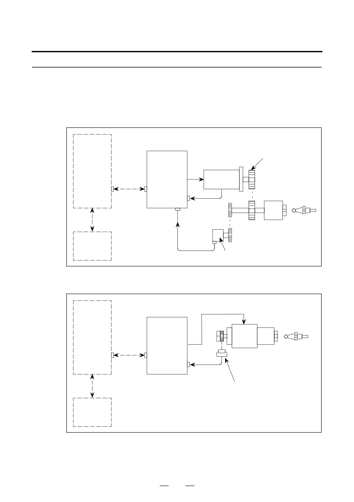
Configuration and
Order Drawing Number
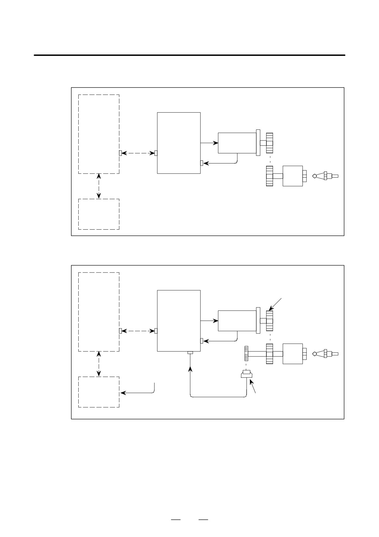
(1) Orientation Using Position Coder
Gear or belt
Spindle
amplifier
(SPM)
CNC
Communica-
Spindle
tion cable
motor
JA7B
Spindle
JY2
Tool
Speed
JY4
feedback
ÅÅ
Connected directly, gear or
Power
timing belt (1:1)
Position
magnetic
feedback
sequence
control circuit
α Position coder
(2) Orientation Using Built-in Motor
Spindle
Spindle
Tool
amplifier
(SPM)
CNC
Communica-
ÅÅ
tion cable
Built-in
JA7B
spindle motor
JY2
Speed and
position
feedback
Bz sensor
Power
magnetic
sequence
control circuit
436
B-65162E/03
11. OPTION RELATED TO SPINDLE
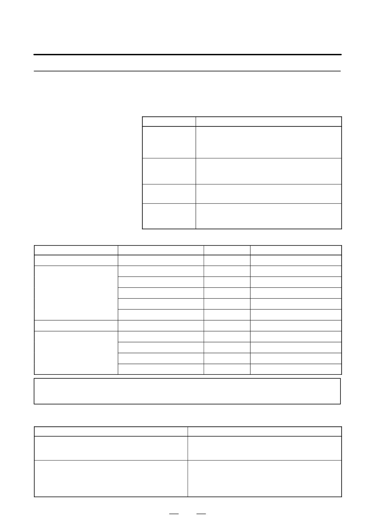
(3) Orientation Using a Motor with Mz Sensor
Spindle
amplifier
(SPM)
CNC
Spindle mo-
Communica-
tor with MZ
tion cable
sensor
JA7B
Spindle
JY2
Tool
Speed and
position
ÅÅ
feedback
Connected directly, gear or
Power
timing belt (1:1)
magnetic
sequence
control circuit
(4) Orientation Using Bz Sensor on the Spindle
Gear or belt
Spindle
amplifier
(SPM-TYPE2)
CNC
Spindle
motor
Spindle
JY5
Tool
Speed
JY2
feedback
ÅÅ
Connected directly, gear or
Power
timing belt (1:1)
Position
magnetic
feedback
sequence
Bz sensor
control circuit
437
11. OPTION RELATED TO SPINDLE
B-65162E/03
11.1.1.4
Specifications
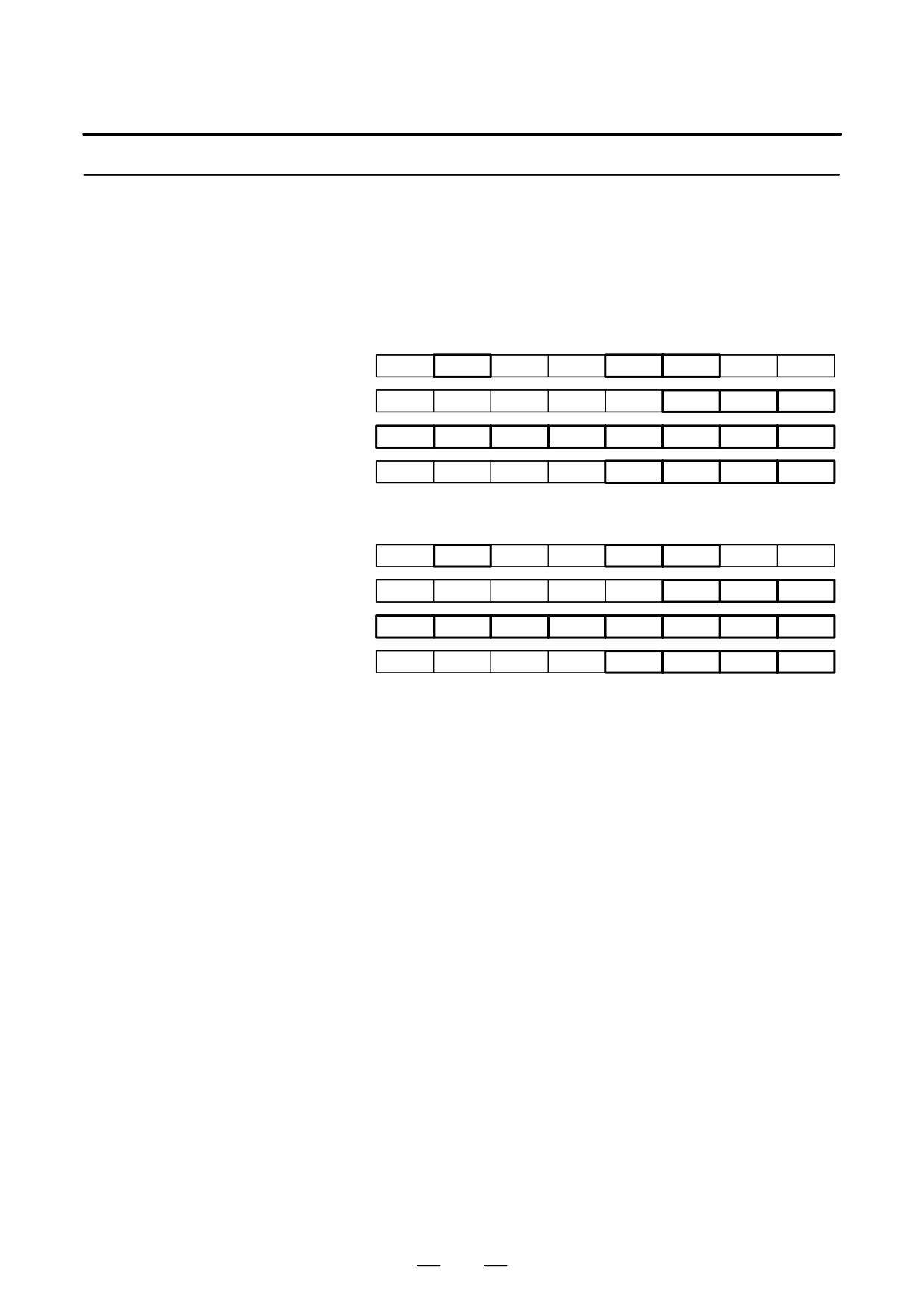
(1) Detector
Detector
Description
Connected to a spindle on a one-to-one basis
(directly, or via a gear or timing belt)
Position coder
1024 pulses/rev (phase A signal, phase B signal)
1 pulse/rev (one-rotation signal)
MZ sensor
BZ sensor
Connected to a spindle on a one-to-one basis
(Built-in sensor)
High-resolution
Connected to a spindle on a one-to-one basis
position coder
(directly, or via a gear or timing belt)
High-resolution
magnetic pulse
Connected to a spindle on a one-to-one basis
coder
(2) Detection Unit and Positioning Repeatability
Detector
Number of feedback signals
Detection unit
Positioning repeatability (Note)
Position coder
1024p/rev
0.088_
"0.2_
64λ/rev
0.167_
"0.4_
128λ/rev
0.167_
"0.4_
MZ sensor
BZ sensor
256λ/rev
0.088_
"0.2_
(Built–in sensor)
384λ/rev
0.088_
"0.2_
512λ/rev
0.088_
"0.2_
High-resolution position coder
1024p/rev
0.088_
"0.2_
128λ/rev
0.088_
"0.2_
192λ/rev
0.088_
"0.2_
High-resolution magnetic pulse
coder
256λ/rev
0.088_
"0.2_
384λ/rev
0.088_
"0.2_
NOTE
Machine error factors are excluded.
(3) Method of stop position specification
Method of stop position specification
Description
Specify the number of pulses ("4095 pulses) from a one-
Parameter-based specification
rotation signal to a stop position with a parameter
(360_ = 4096 pulses).
Specify the number of pulses ("4095 pulses) from a one-
rotation signal to a stop position with a PMC signal
External stop position setting type
(360_ = 4096 pulses). The sum of the number of pulses spe-
cified with the parameter and the number of pulses specified
with the PMC signal represents a final stop position.
438
B-65162E/03
11. OPTION RELATED TO SPINDLE
11.1.1.5
Signal Explanation
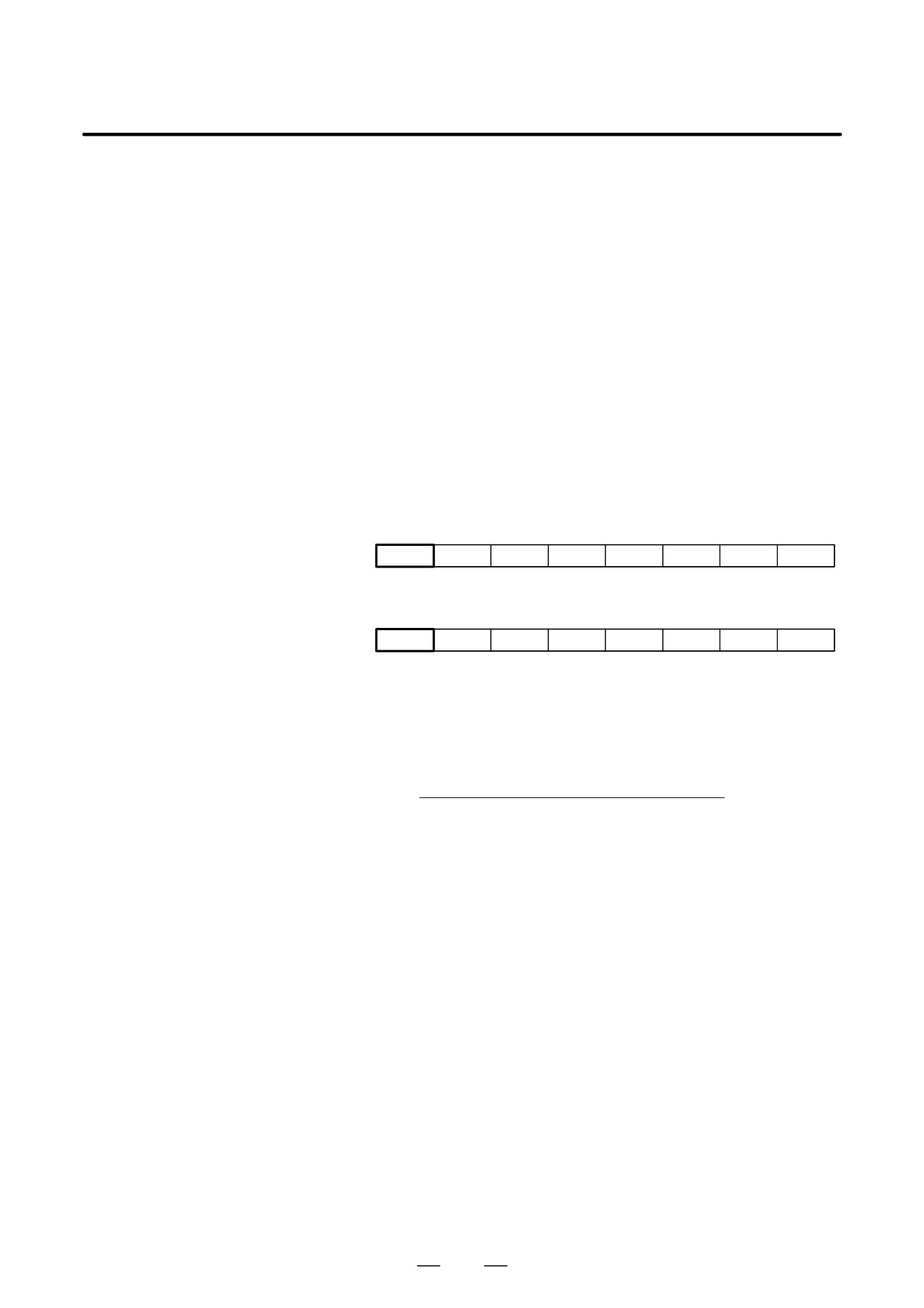
(1) DI Signals (PMC to CNC)
(a) Signal address
First spindle control input signal
FS0
FS15
FS16
#7
#6
#5
#4
#3
#2
#1
#0
: G229
G227
G070
MRDYA
ORCMA
SFRA
SRVA
CTH1A
CTH2A
TLMHA
TLMLA
: G231
G229
G072
RCHHGA
MFNHGA
INCMDA
OVRA
DEFMDA
NRROA
ROTAA
INDXA
: G110
G231
G078
SHA07
SHA06
SHA05
SHA04
SHA03
SHA02
SHA01
SHA00
: G111
G230
G079
SHA11
SHA10
SHA01
SHA00
Second spindle control input signals
FS0
FS15
FS16
#7
#6
#5
#4
#3
#2
#1
#0
: G223
G235
G074
MRDYB
ORCMB
SFRB
SRVB
CTH1B
CTH2B
TLMHB
TLMLB
: G235
G237
G076
RCHHGB
MFNHGB
INCMDB
OVRB
DEFMDB
NRROB
ROTAB
INDXB
: G112
G239
G080
SHB07
SHB06
SHB05
SHB04
SHB03
SHB02
SHB01
SHB00
: G113
G238
G081
SHB11
SHB10
SHB09
SHB08
Details of signals
(b) Orientation (fixed position stop) command (ORCMA)
D This command signal is used to stop spindle movement at the preset
position to allow tool change and workpiece loading/unloading.
D When this signal is specified as ”1” while the spindle is rotating, the
rotation decelerates immediately and the spindle stops at the preset
position.
D When the orientation command is issued, set the spindle
forward/reverse rotation command (SFRA, SRVA) to ”0” for safety.
By means of this, the spindle will not start to rotate even in the unlikely
event ORCMA becomes ”0” during tool change.
D Set this signal to
”0” by the tool change completion signal or
workpiece loading/unloading completion signal.
D Always set the orientation command signal to ”0” when turning on
power.
D When an emergency stop occurs during orientation, the orientation
command signal must be reset (”0”).
Return the ATC arm to the safe position so that it will not be damaged
if the spindle or tool rotates when the power is turned on.
(c) Gear/clutch signal (CTH1A, CTH2A)
D These signals are used for switching the speed range between high
speed and low speed, or when there are two or more gear steps between
the spindle and spindle motor.
439
11. OPTION RELATED TO SPINDLE
B-65162E/03
D Set the following conditions corresponding to the clutch or gear state.
They are used in order to select the spindle control parameter (Position
gain, Gear ratio, velocity loop gain).
CTH1A CTH2A
0
0
: HIGH GEAR
0
1
: MEDIUM HIGH GEAR
1
0
: MEDIUM LOW GEAR
1
1
: LOW GEAR
(d)
Command for changing the stop position in spindle orientation (INDXA)
D This command is used when the orientation position is changed again
immediately after spindle orientation was just performed.
This command is valid when the spindle orientation command
(ORCMA) is issued.
D Changing this signal from 1 to 0 orients the spindle within one rotation
to a new position (absolute position within one rotation) specified by
new stop position data (SHA11 to SHA00).
D The direction of spindle rotation is specified by the direction
command for the shorter route (NRROA) or the command specifying
the direction of rotation (ROTTA).
D This function is valid when the CNC parameter corresponding to the
spindle orientation function in which the stop position is specified
externally is set.
(e)
Direction command for the shorter route when the stop position changes in spindle orientation (NRROA)
D This command is used for specifying the direction of rotation,
whichever is shortest, (within "180 degrees) when the orientation
position is changed again immediately after spindle orientation has
just been performed.
D When this signal is set to 1, positioning is performed in the direction
that provides a shorter route, irrespective of the command specifying
the direction of rotation when the stop position changes in spindle
orientation.
(f)
Command specifying the direction of rotation when the stop position changes in spindle orientation (ROTAA)
D This command is used for specifying the direction of rotation when the
orientation position is changed again immediately after the spindle
orientation was just performed.
When the signal is 0, the spindle rotates counterclockwise to the
specified position and stops.
When the signal is 1, the spindle rotates clockwise to the specified
position and stops.
D This command is valid when the direction command for the shorter
route when the stop position changes in spindle orientation (NRROA)
is 0.
440
B-65162E/03
11. OPTION RELATED TO SPINDLE
(g)
Spindle orientation command in which the stop position is specified externally (SHA11 to SHA00)
D This command is used for specifying a stop position with an absolute
position within one rotation in the following equation:
11
360
Stop position (degrees) +
ȍ
(2i
Pi)
4096
i+0
where
Pi = 0 when SHAi = 0
Pi = 1 when SHAi = 1
D When this command is used, the stop position parameters in spindle
orientation with a position coder (In case of Series 16 : No. 4031) are
invalid.
(2)
Output Signals (CNC to PMC)
(a)
Signal addresses
First spindle control output signal
FS0
FS15
FS16
#7
#6
#5
#4
#3
#2
#1
#0
: F281
F229
F405
ORARA
TLMA
LDT2A
LDT1A
SARA
SDTA
SSTA
ALMA
Second spindle control output signals
FS0
FS15
FS16
#7
#6
#5
#4
#3
#2
#1
#0
: F285
F245
F049
ORARB
TLMB
LDT2B
LDT1B
SARB
SDTB
SSTB
ALMB
(b)
Orientation (fixed position stop) completion signal (ORARA)
D When the orientation command is input and the spindle has stopped
near the preset fixed position (for example, within "1°), it becomes
”1”.
Condition for ORARA to become ”1”
(ORCMA is ”1”)
(zero-speed signal SSTA is ”1”)
=
Near to fixed position
Near to fixed position is set to the parameter in case of Series 16
(PRM4075=Orientation complete signal detection level).
If the above 3 conditions are satisfied, the orientation complete signal
is output.
If the orientation completion signal is not issued within a set period of
time after the orientation command signal is input, it is considered to
be abnormal. So it should be detected by the power magnetic sequence
and an orientation alarm should be issued.
D Tool change or workpiece loading/ unloading operations can be started
when this signal is ”1”.
441
11. OPTION RELATED TO SPINDLE
B-65162E/03
D
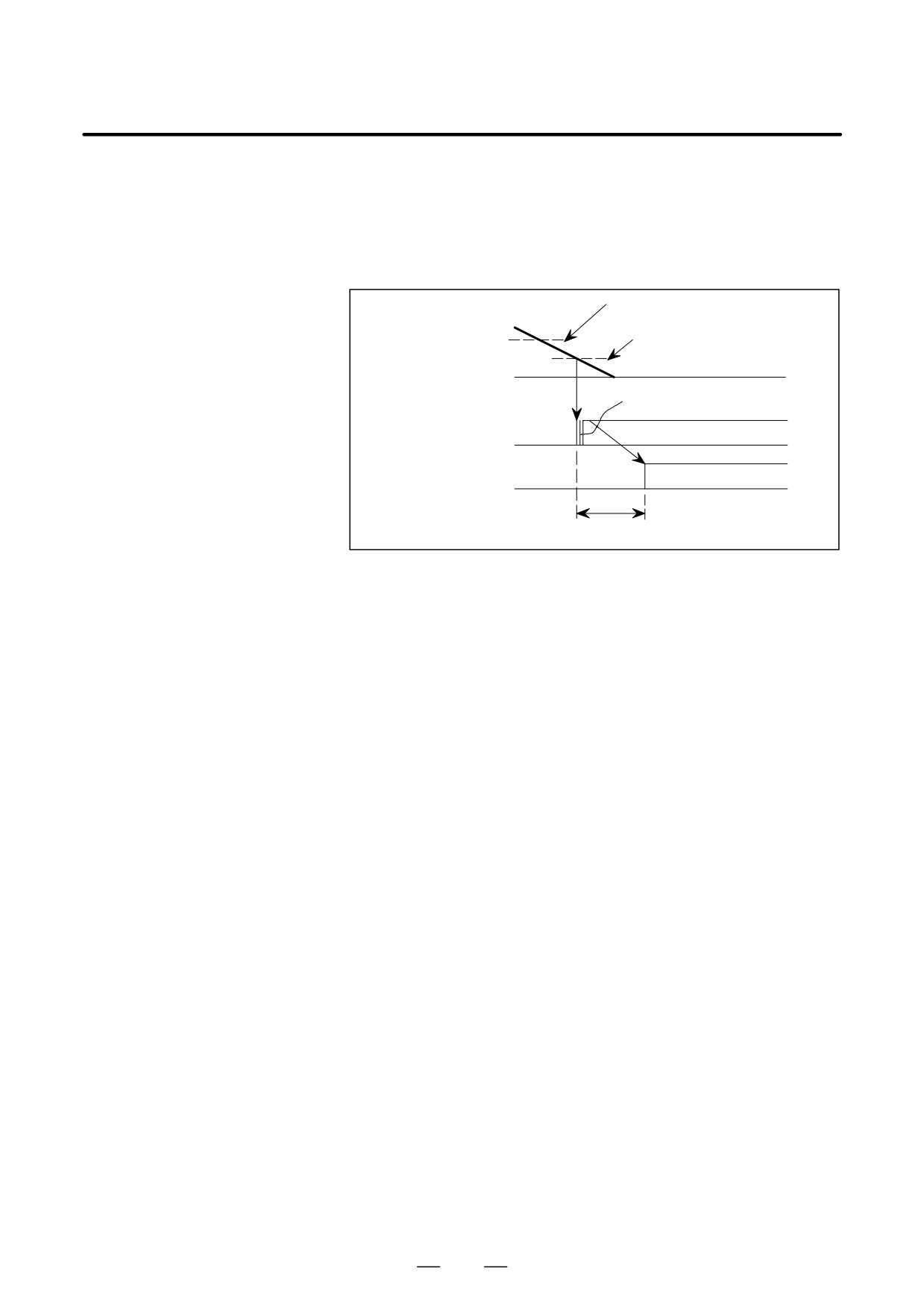
The spindle orientation completion signal is issued when the spindle
is within "1° of the preset position and so it does not always indicate
that the spindle has stopped completely. Some machines allow a very
short operation time for the ATC arm to grip the tool. In this case, start
the ATC arm operation after a short time (0.1 to 0.5 sec.) so that the
arm will grip the tool when the spindle has stopped completely.
Zero-speed detection command
Spindle speed
Within "1° of the stop
position
Chattering
Orientation completion
sequence ORARA
ATC arm operation
start signal
0.1 to 0.5 sec
D
This signal will become ”0” during a tool change if the spindle is
pushed away from the preset position by external force.
In this case, design a power magnetic sequence so that the tool change
operation is interrupted.
However, do not release the orientation command, and if the
orientation completion signal is issued again, perform a tool change.
D
If the automatic tool change (ATC) structure is such that it may cause
serious damage if a malfunction occurs, install a proximity switch to
generate a verification signal when the ATC enters an area in which the
automatic tool change operation can be performed. In addition to this,
perform a double safety check by the power magnetic sequence and
carry out a tool change.
442
B-65162E/03
11. OPTION RELATED TO SPINDLE
11.1.1.6
Sequences
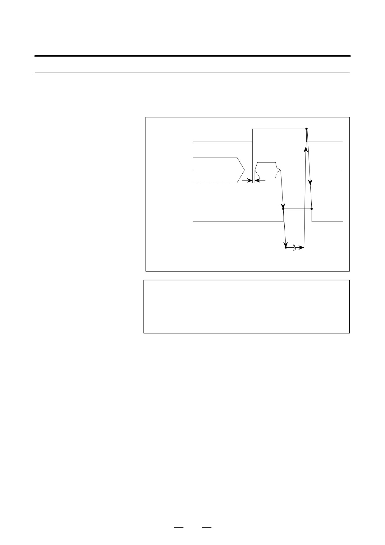
(1) Orientation Command while Stopping
1
Orientation command
0
0
ORCMA
Stop
CW direction
Stop
Motor speed
CCW direction
Note
15 to 20 ms
1
Orientation completion signal
0
0
ORARA
ATC operation
Start
Completion
ATC
operation
NOTE
The spindle motor rotation direction can be changed by setting.
In standard setting, the spindle motor will stop at the fixed
position in the direction the spindle motor was rotating
before this orientation command signal was generated.
443
11. OPTION RELATED TO SPINDLE
B-65162E/03
(2)
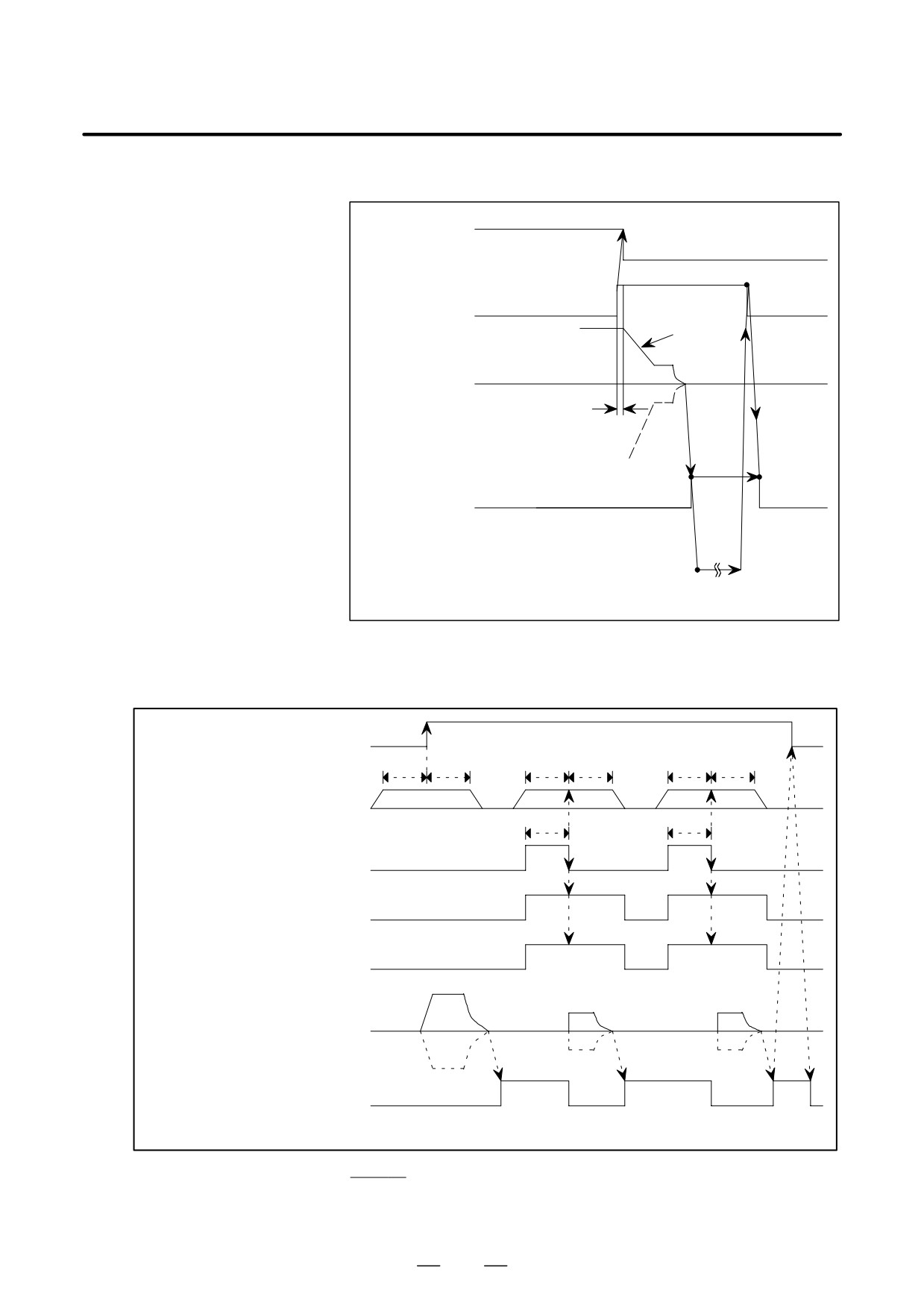
Orientation Command During High-speed Rotation
Rotation command
1
SFRA, SRVA
(Configuration at
external sequence)
0
1
Orientation command
ORCMA
0
0
Deceleration
High-speed
CW direction
Motor speed
15 to 20 ms
CCW direction
1
Orientation completion signal
0
0
ORARA
ATC operation
Start
Completion
ATC
operation
(3)
When Stop Position External Setting Type Spindle Orientation Function is Used
D Sequence
Spindle orientation command
ORCMA
t
t
t
t
t
t
Spindle orientation stop posi-
tion command SHA00-11
t
t
Spindle orientation stop position
(Note 1)
changing command INDXA
Rotating direction command
when spindle orientation stop
(Note 2)
position is changed ROTAA
(Note 2)
Shorter route command when
spindle orientation stop posi-
tion is changed NRROA
CW
direction
Stop
Stop
Stop
Motor speed
CCW direction
Spindle orientation completion
signal ORARA
Set t to 50msec or more.
Stop
D Stopping in a specified
position through a
normal orientation
command
444
B-65162E/03
11. OPTION RELATED TO SPINDLE
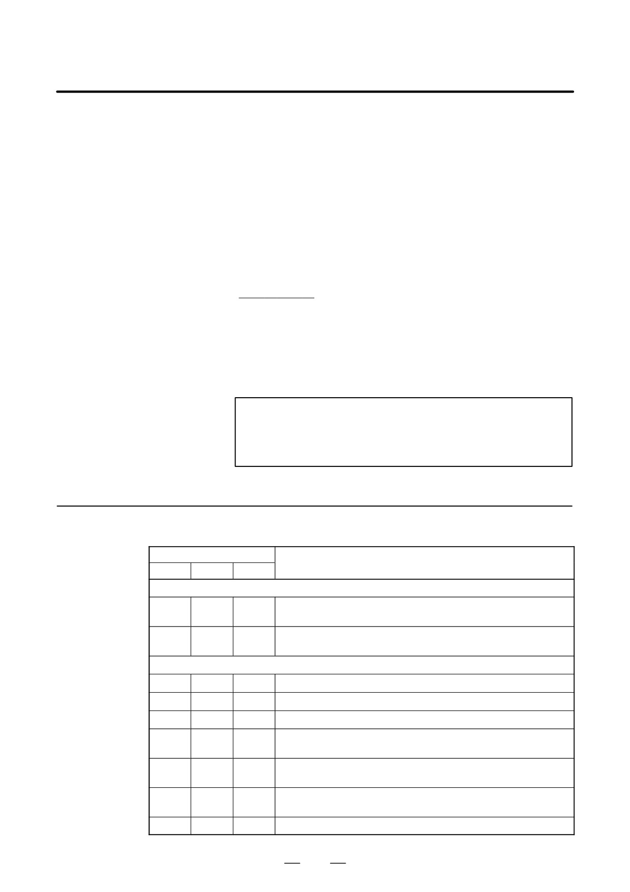
D The rotating direction of the spindle motor is specified by setting a
parameter.
D When the motor rotates first after the power has been turned on, it
rotates at the orientation speed and stops in a specified position after
the one rotation signal has been captured. When it rotates next or later,
it stops in the specified position within one rotation.
D With the spindle orientation function in which a stop position is
externally specified, if the data of SHA11-00 (spindle orientation stop
position command) is decided in a second or later stop operation, the
motor stops at a position ([one-rotation signal position] + [data
specified by SHA11-00] + [PRM4077]) shifted by the value seized on
a rising edge of ORCMA (spindle orientation command).
Stop and
D Stopping in a specified position using the stop position external setting
type spindle orientation function
D The rotating direction of the spindle motor is specified by the
following command: (1) rotating direction command when spindle
orientation stop position is changed (ROTA) or, (2) shortcut command
when spindle orientation stop position is changed (NRROA).
NOTE
The spindle orientation stop position change command
INDXA is valid only when the spindle orientation command
ORCMA is set to 1.
11.1.1.7
The table below lists the parameters related to spindle orientation using
a position coder. Refer to the Parameter Manual for details.
Parameters
Parameter No.
Description
FS0
FS15
FS16
Orientation function setting
Whether spindle orientation is used (Set to 1.)
6515#0
3015#0
4015#0
(CNC software option is necessary.)
0080
5609
3702
Whether to use the spindle orientation function of external stop position
#3,#2
#3,#2
#3,#2
setting type. (#2: First spindle, #3: Second spindle)
Setting related to the position coder signal
6501#2
3001#2
4001#2
Whether a position coder signal is used (Set to 1.)
6500#2
3000#2
4000#2
Mounting orientation for the position coder
6500#0
3000#0
4000#0
Rotational direction of the spindle and motor
Selection of position coder method or magnetic sensor method spindle
6503#0
3003#0
4003#0
orientation (0 for a position coder method)
6503
3003
4003#
Setting of the position coder signal
#7, 6, 4
#7, 6, 4
7, 6, 4
Function for detecting position coder one-rotation signal at normal rota-
6517#2
3017#2
4017#2
tion
6598
3098
4098
Position coder signal detection maximum speed
445
11. OPTION RELATED TO SPINDLE
B-65162E/03
Parameter No.
Description
FS0
FS15
FS16
Gear ratio setting
6556 to
3056 to
4056 to
Gear ratio between the spindle and motor
6559
3059
4059
(selected by DI signals CTH1A and CTH2A)
Setting of a rotation direction at orientation time
6503
3003
4003
Rotational direction for spindle orientation
#3, 2
#3, 2
#3, 2
Setting of a stop position shift amount
Stop position for position coder method orientation
6531
3031
4031
(This parameter is invalid when the function for externally setting the
stop position or externally setting incremental commands is used.)
6577
3077
4077
Shift of spindle orientation stop position
Setting related to gain at orientation time
6560 to
3060 to
4060 to
Position gain for orientation
6563
3063
4063
(selected by DI signals CTH1A and CTH2A)
6542
3042
4042
Velocity loop proportional gain for orientation
6543
3043
4043
(selected by DI signal CTH1A)
6550
3050
4050
Velocity loop integral gain for orientation
6551
3051
4051
(selected by DI signal CTH1A)
6564
3064
4064
Change rate for the position gain after spindle orientation
Setting related to gain at orientation time (Continued)
6584
3084
4084
Setting related to orientation speed
6538
3038
4038
Orientation speed
6576
3076
4076
Orientation-time motor speed limit ratio
Setting related to the orientation completion signal
6575
3075
4075
Detection level for the spindle orientation completion signal
Detection level for the approach signal for position coder method
6276
3456
4312
orientation
Others
6517#7
3017#7
4017#7
Shorter route function for orientation from stop state
11.1.1.8
High-speed
Orientation
(1) Overview
The high-speed orientation function reduces spindle orientation time by:
1 Making full use of the motor deceleration capability
2 Increasing the gain of the position loop
446
B-65162E/03
11. OPTION RELATED TO SPINDLE
NOTE
1
This function can also be used for spindle orientation of
external stop position setting type and incremental
command type.
2
This function cannot be used for orientation during spindle
synchronization.
(2) System configuration
The high-speed orientation function can be used with the following
system configurations:
1) System in which a position coder connected to a spindle on a
one-to-one basis is installed
2) Motor system built into a spindle
3) System in which a motor with a built-in MZ sensor is connected
to a spindle on a one-to-one basis
NOTE
This function cannot be used with an orientation system of
external one-rotation signal type that uses a proximity
switch.
(3) Signal
See Section 11.1.1.5.
(4) Description of operation
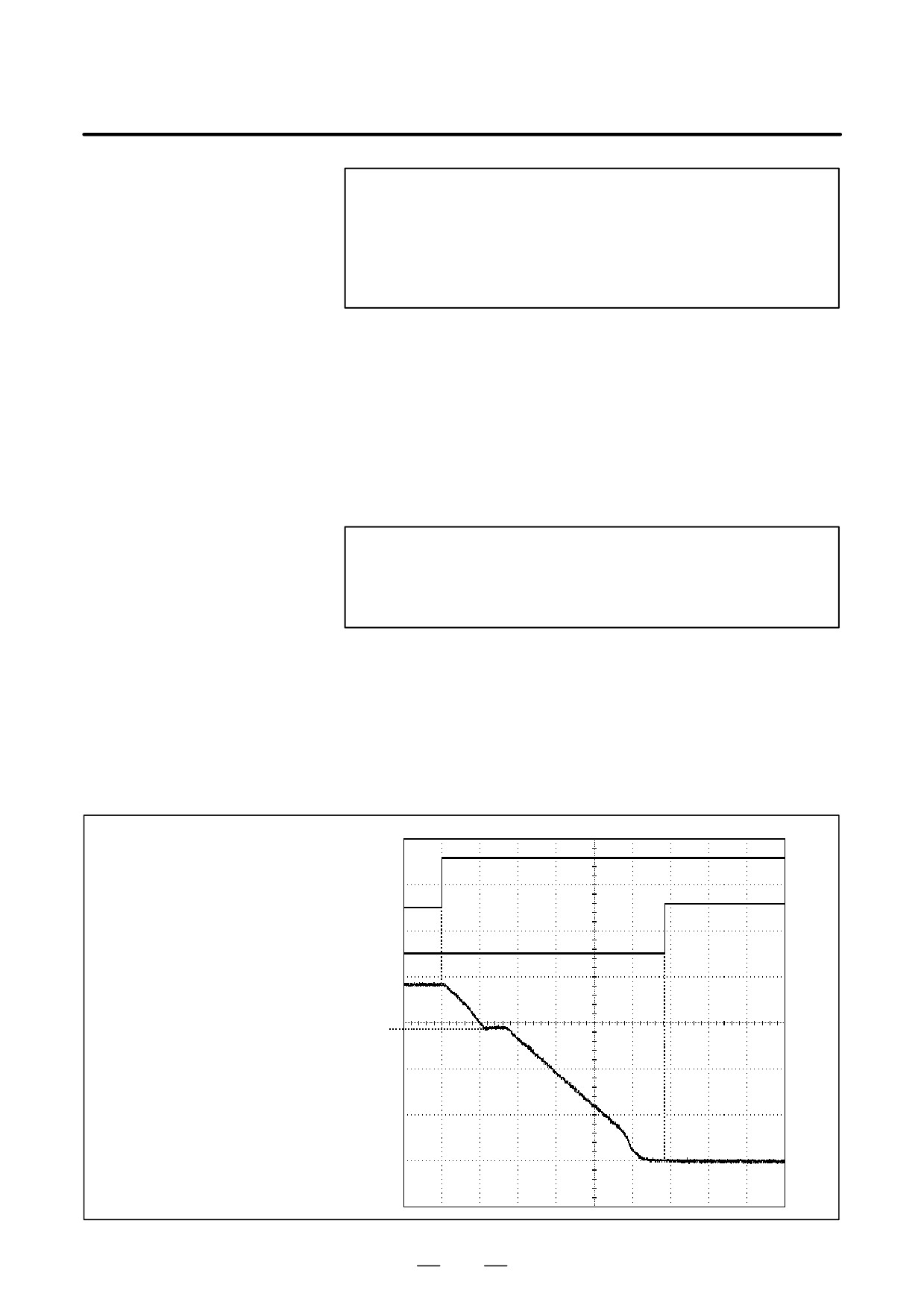
1) When orientation operation is started from a speed higher than the
upper orientation speed limit
ORCMA (orientation command)
ORARA (orientation completion signal)
Motor speed
Upper orientation speed limit
447
11. OPTION RELATED TO SPINDLE
B-65162E/03
If a spindle orientation command (ORCMA) is entered when the
speed is higher than the upper orientation speed limit set with
parameter No. 4038 (FS16), the speed is reduced to the upper
orientation speed limit.
A one-rotation signal is detected (only for the first orientation after
power-on).
The speed is reduced according to the motor deceleration time
constant set with parameter No. 4320 to No. 4323 (FS16).
When the speed becomes equal to or less than a value calculated
internally by software, the position loop is controlled according to
the orientation-time position gain set with parameter No. 4060 to
No. 4063 (FS16).
When the positional deviation becomes equal to or less than the
number or pulses set with parameter No.
4075 (FS16) for
specifying an orientation completion signal level, the spindle
orientation completion signal (ORARA) is output.
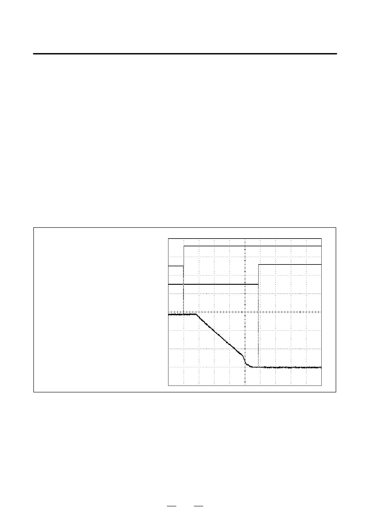
2) When orientation operation is started from a speed between the lower
orientation speed limit and higher orientation speed limit
ORCMA (orientation command)
ORARA (orientation completion signal)
Motor speed
If a spindle orientation command (ORCMA) is entered when the
speed is between the upper orientation speed limit set with
parameter No. 4038 (FS16) and the lower orientation speed limit
(calculated internally by software), a one-rotation signal is
detected (only for the first orientation after power-on).
The speed is reduced according to the motor deceleration time
constant set with parameter No. 4320 to No. 4323 (FS16).
When the speed becomes equal to or less than a value calculated
internally by software, the position loop is controlled according to
the orientation-time position gain set with parameter No. 4060 to
No. 4063 (FS16).
448
B-65162E/03
11. OPTION RELATED TO SPINDLE
When the positional deviation becomes equal to or less than the
number or pulses set with a parameter (orientation completion
signal level [parameter No. 4075 for FS16]), the spindle orientation
completion signal (ORARA) is output.
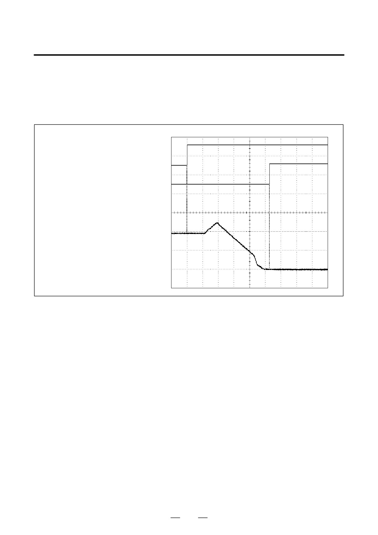
3) When an orientation operation is started from a speed lower than the
lower orientation speed limit
ORCMA (orientation command)
ORARA (orientation completion signal)
Motor speed
If a spindle orientation command (ORCMA) is entered when the
speed is lower than the lower orientation speed limit (calculated
internally by software), a one-rotation signal is detected (only for
the first orientation after power-on).
The speed is increased according to the motor deceleration time
constant set with parameter No. 4320 to No. 4323 (FS16).
The speed is reduced according to the motor deceleration time
constant set with parameters No. 4320 to No. 4323 (FS16).
When the speed becomes equal to or less than a value calculated
internally by software, the position loop is controlled according to
the orientation-time position gain set with parameters No. 4060 to
No. 4063 (FS16).
When the positional deviation becomes equal to or less than the
number or pulses set with a parameter (parameter No. 4075 for
FS16) for specifying an orientation completion signal level, the
spindle orientation completion signal (ORARA) is output.
449

11. OPTION RELATED TO SPINDLE
B-65162E/03
(5) Parameter list
The table lists the parameters to be newly set to use the high-speed
orientation function.
Parameter No.
Description
FS0
FS15
FS16
6518#6
3018#6
4018#6
High-speed orientation function
Whether to perform speed command compensa-
6518#5
3018#5
4018#5
tion at high-speed orientation
6538
3038
4038
Upper spindle orientation speed limit
6564
3064
4064
Deceleration time constant limit ratio
6284
3464
4320
Motor deceleration time constant (Parameters
to
to
to
are selected by input signals CTH1A and
6287
3467
4323
CTH2A.)
6290
3470
4326
Deceleration time constant limit start speed (Pa-
6294
3474
4330
rameters are selected by input signal CTH1A.)
11.1.2
Spindle Orientation of
Position Coder Type
(αC Series)
11.1.2.1
Unlike methods that use a stopper and so forth to stop the spindle
mechanically at a specified position, orientation of position coder type
Overview
stops the spindle at a specified position by collecting position feedback
data directly from the position coder that is connected to the spindle.
450
B-65162E/03
11. OPTION RELATED TO SPINDLE
11.1.2.2
Features
(1)
Elimination of the mechanical section
Spindle orientation is enabled simply by connecting a position coder to
the spindle. The mechanical stop mechanism (stopper, pin, and so forth)
is not required for orientation.
(2)
Reduced orientation time
A spindle motor connected with a spindle is used. So, orientation is
possible at high speed, regardless of the gear shift. This significantly
reduces orientation time.
(3)
Simplified power magnetics sequence
The sequence consists of an orientation command, orientation
completion command, and clutch/gear signal. It does not require any
other signals. This means that sequences for orientation speed
specification and torque limit specification are not required.
(4)
Improved reliability
This type of spindle orientation does not depend on mechanical
components, and therefore is not subject to mechanical damage due to
external shock. Thus, a higher level of reliability is possible.
(5)
Workpiece positioning enabled
On a lathe, a workpiece can be positioned for workpiece
attachment/detachment direction alignment.
(6)
Reduced number of boring steps
Positioning from the same direction as the spindle direction is possible
upon the completion of boring, so that the workpiece is not damaged by
the tool tip. In addition, a tool tip can be attached/detached in one
direction with respect to the workpiece, so that programs can be created
easily.
451
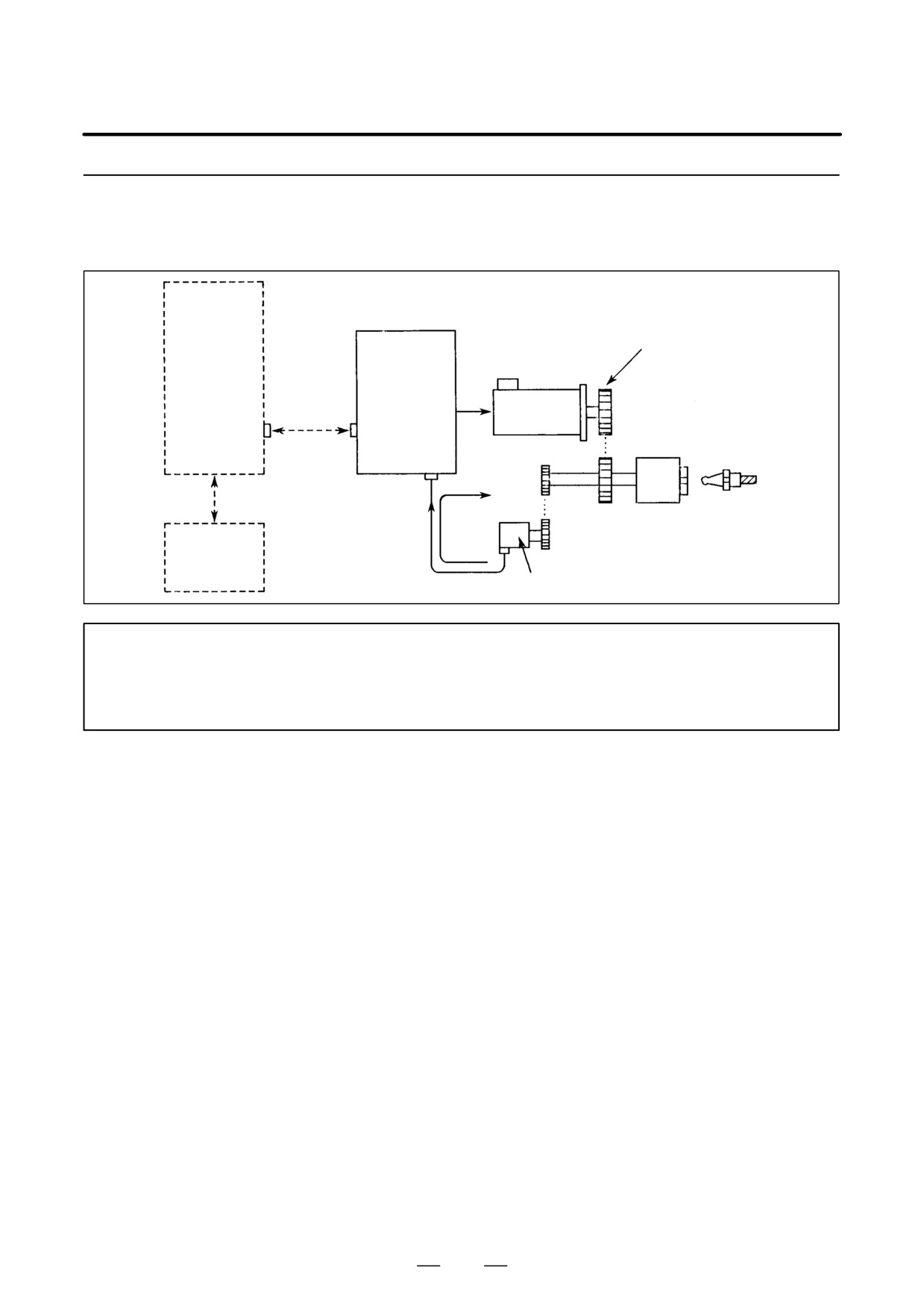
11. OPTION RELATED TO SPINDLE
B-65162E/03
11.1.2.3
System Configuration
Spindle
Gear or belt
amplifier
CNC
(SPMC)
Communica-
tion cable
Spindle
motor
JA7B
Spindle
Tool
JY4
Position
feedback
Direct connection, or gear or
Power
loop
timing belt (one-to-one)
magnetics
sequence
circuit
αposition coder
NOTE
When an αC series spindle is used, orientation is possible only with a system where the spindle
is connected to a position coder on a one-to-one basis. (Orientation is not possible when other
detectors and connection ratios are involved.)
452