FANUC SERVO AMPLIFIER a series. DESCRIPTIONS (B-65162E/03) - page 17
B-65162E/03
11. OPTION RELATED TO SPINDLE
11.1.5.7
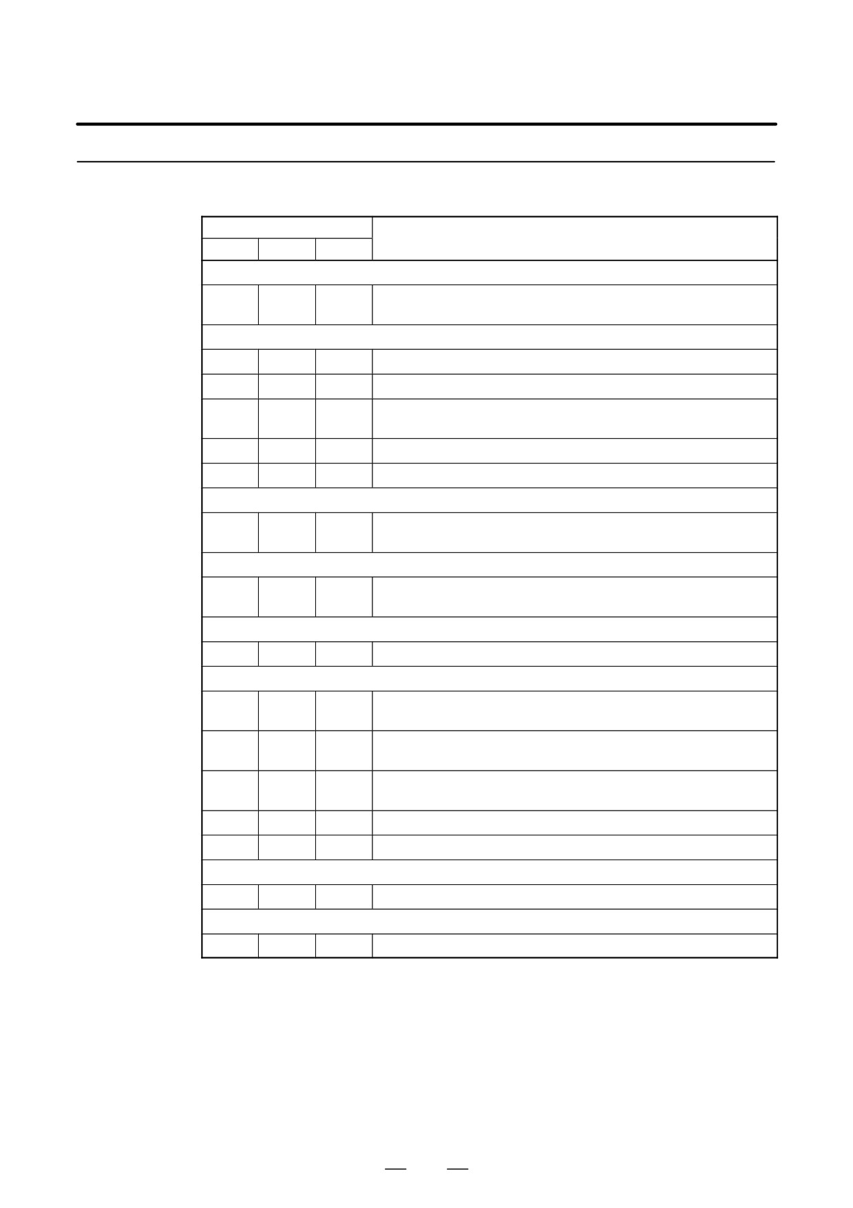
The table below lists the parameters related to spindle orientation using
a magnetic sensor. Refer to the Parameter Manual for details.
Parameters
Parameter No.
Description
FS0
FS15
FS16
Orientation function setting
Whether spindle orientation is used (Set to 1.)
6515#0
3015#0
4015#0
(CNC software option is necessary.)
Setting related to the magnetic sensor signal
6501#3
3001#3
4001#3
Mounting orientation for the magnetic sensor
6500#0
3000#0
4000#0
Rotational direction of the spindle and motor
Selection of a position coder method magnetic sensor method spindle
6503#0
3003#0
4003#0
orientation (1 for a magnetic sensor method)
6578
3078
4078
MS signal constant
6579
3079
4079
MS signal gain adjustment
Gear ratio setting
6556 to
3056 to
4056 to
Gear ratio between the spindle and motor
6559
3059
4059
(selected by DI signals CTH1A and CTH2A)
Setting of a rotation direction at orientation time
6503
3003
4003
Rotational direction for spindle orientation
#3, 2
#3, 2
#3, 2
Setting of a stop position shift amount
6577
3077
4077
Shift of spindle orientation stop position
Setting related to gain at orientation time
6560 to
3060 to
4060 to
Position gain for orientation
6563
3063
4063
(selected by DI signals CTH1A and CTH2A)
6542
3042
4042
Velocity loop proportional gain for orientation
6543
3043
4043
(selected by DI signal CTH1A)
6550
3050
4050
Velocity loop integral gain for orientation
6551
3051
4051
(selected by DI signal CTH1A)
6564
3064
4064
Change rate for the position gain after spindle orientation
6584
3084
4084
Motor voltage for spindle orientation
Setting related to orientation speed
6576
3076
4076
Motor speed regulation rate for spindle orientation
Setting related to the orientation completion signal
6575
3075
4075
Detection level for the spindle orientation completion signal
483
11. OPTION RELATED TO SPINDLE
B-65162E/03
11.2
RIGID TAPPING
11.2.1
Rigid tapping is a function for tapping based on synchronous control over
spindle and tapping axis operation.
Overview
This section describes the rigid tapping function associated with the
spindle.
11.2.2
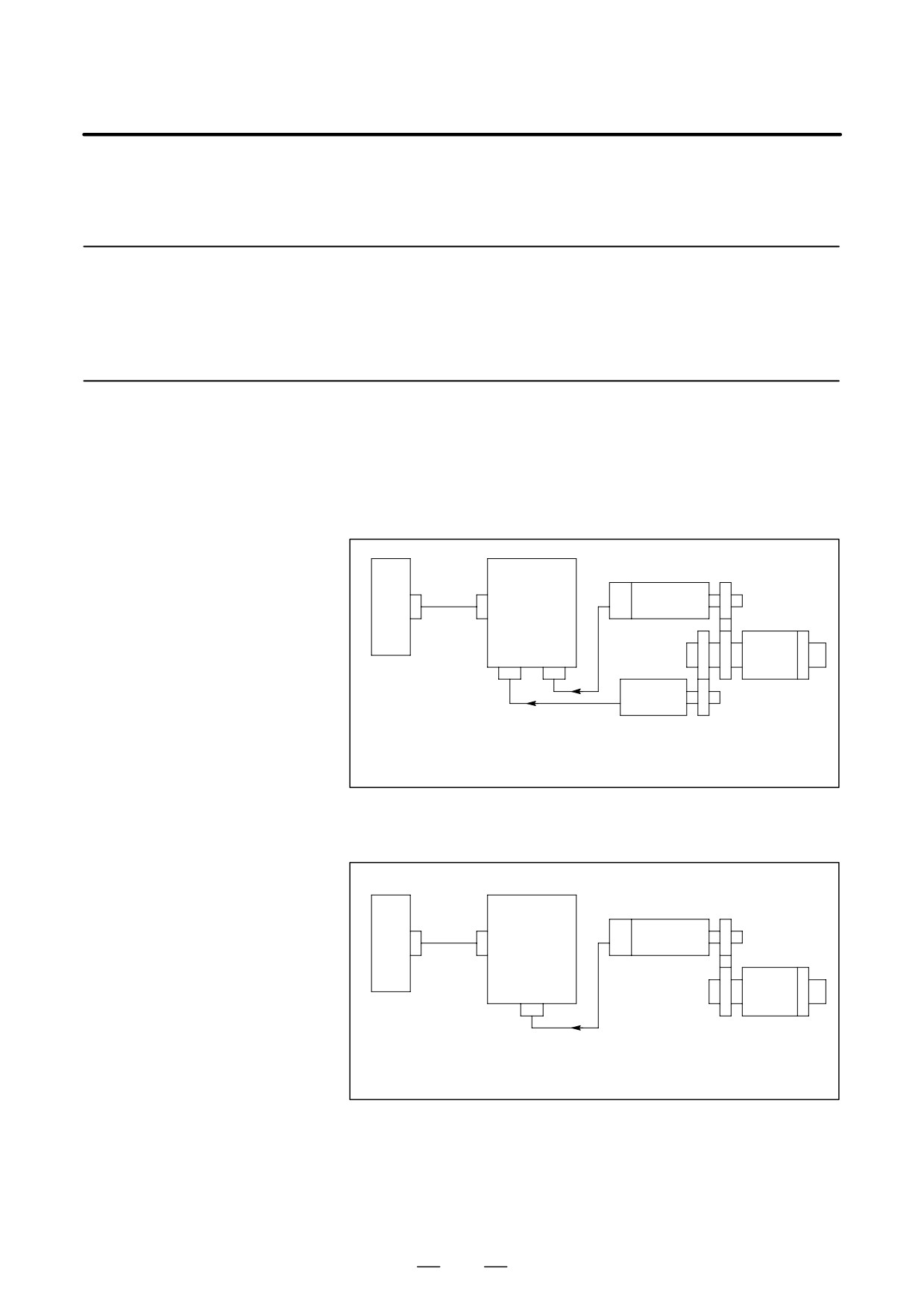
System Configuration
(1)
αC Series Spindle
(a)
System where a position coder is attached to the spindle
Gear ratio
Commu-
m : n
CNC
Spindle
nication
amplifier
cable
Spindle
Belt or gear
module
motor
connection
(SPM)
Verocity
JY4
JY2
Spindle
feedback
Position
Gear or timing
coder
belt
Position
1 : 1
feedback
1 : 2
1 : 4
1 : 8
(b)
System where a spindle motor with a built-in MZ sensor is used (including that case where a built-in motor
is used)
Gear ratio
Commu-
m : n
CNC
Spindle
Built-in sensor
nication
amplifier
cable
Spindle
Gear or
module
motor
timing belt
(SPM)
JY2
Spindle
Position and
velocity
feedback
484
B-65162E/03
11. OPTION RELATED TO SPINDLE
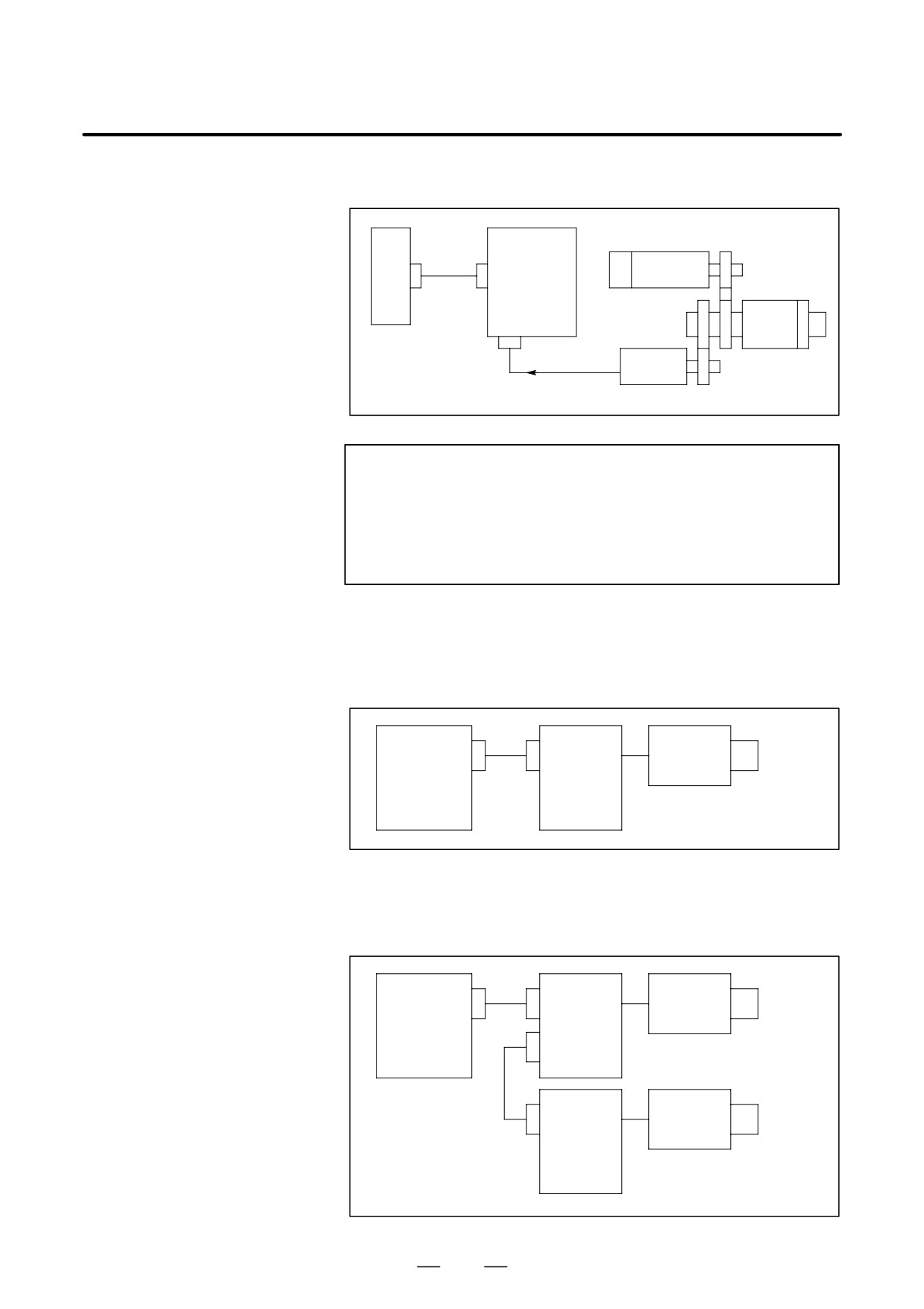
(2) αC Series Spindle
Gear ratio
Commu-
m : n
CNC
Spindle
nication
amplifier
cable
Spindle
Belt or gear
module
motor
connection
(SPMC)
Verocity
JY4
Spindle
feedback
Position
Gear or timing
coder
belt
Position feedback
1 : 1
NOTE
Only 1:1 is allowed between the spindle and position coder.
A motor used with the αC series spindle has no speed
sensor, so that the acceleration/deceleration capability and
synchronization control precision are degraded relative to
the α series.
(3) CNC-based Classification of System Configurations
(a) When FS16-M, FS15-T/M, or FS0-M is used
Spindle
First
Spindle
FS16-M
motor
spindle
amplifier
FS15-T/M
(SPM or
FS0-M
SPMC)
(b) When FS16-T or FS0-T is used
When rigid tapping is performed using the second spindle, the
multi-spindle control function option is required.
Spindle
First
Spindle
motor
spindle
FS16-T
amplifier
FS0-T
(SPM)
Spindle
Second
Spindle
motor
spindle
amplifier
(SPM or
SPMC)
485
11. OPTION RELATED TO SPINDLE
B-65162E/03
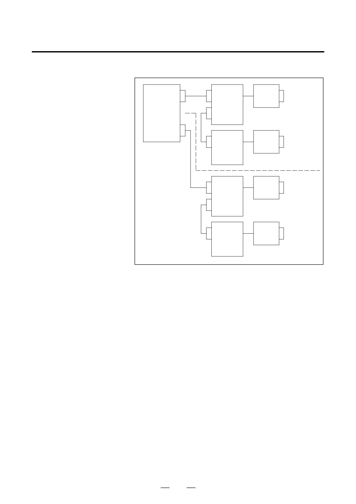
(c) When FS16-TT or FS0-TT is used
Spindle
Tool post 1 -
Spindle
motor
First spindle
amplifier
FS16-TT
(SPM)
FS0-TT
Spindle
Spindle
Tool post 1 -
amplifier
motor
Second
(SPM or
spindle
SPMC)
Spindle
Tool post 2 -
Spindle
motor
First spindle
amplifier
(SPM)
Spindle
Spindle
Tool post 2 -
amplifier
motor
Second
(SPM or
spindle
SPMC)
486
B-65162E/03
11. OPTION RELATED TO SPINDLE
11.2.3
Signals
(1) Signal Addresses
(a) Input signals (PMC to CNC)
[When FS16 is used]
TT
#7
#6
#5
#4
#3
#2
#1
#0
HEAD2
G028
G1028
GR2
GR1
G061
G1061
RGTAP
SWS2
SWS1
G027
G1027
(Note 1)
(Note 1)
GR21
G029
G1029
(Note 2)
G070
G1070
SFRA
CTH1A
CTH2A
NOTE
1
The multi-spindle control function allows rigid tapping to be
performed using the second spindle.
When SWS1 = 1, rigid tapping is performed using the first
spindle (regardless of the setting of SWS2).
When SWS1 = 0, and SWS2 = 1, rigid tapping is performed
using the second spindle.
2
The signal is used as the gear signal when rigid tapping is
performed using the second spindle. Depending on the
GR21 signal, the first and second rows of the gear-by-gear
parameters common to those of the first spindle are used.
[When FS15 is used]
#7
#6
#5
#4
#3
#2
#1
#0
SPSTP
G026
SFRA
CTH1A
CTH2A
G227
[When FS0 is used]
0TTC
#7
#6
#5
#4
#3
#2
#1
#0
HEAD2
GR2
GR1
G118
G1318
(Note 1)
(Note 1)
GR2
GR1
RGTPN
G123
G1323
(Note 2)
(Note 2)
(Note 3)
RGTAP
G135
G1335
(Note 4)
GR21
SWS2
SWS1
G145
G1345
(Note 6)
(Note 5)
(Note 5)
G229
G1429
SFRA
CTH1A
CTH2A
487
11. OPTION RELATED TO SPINDLE
B-65162E/03
NOTE
1
The signals at these addresses are valid when the T series
is used, and bit 5 of parameter No. 0031 is set to 0.
2
The signals at these addresses are valid when the T series
is used and bit 5 of parameter No. 0031 is set to 1. The
signals at these addresses are also valid when the M series
is used, and the constant surface speed option is selected.
3
The signal at this address is valid when bit 4 of parameter
No. 0019 is set to 0.
(With the T and TT series, only this
signal is valid at all times.)
4
The signal at this address is valid when bit 4 of parameter
No. 0019 is set to 1. (With the T and TT series, this signal
is invalid.)
5
The multi-spindle control function allows rigid tapping to be
performed using the second spindle.
When SWS1 = 1, rigid tapping is performed using the first
spindle (regardless of the setting of SWS2).
When SWS1 = 0, and SWS2 = 1, rigid tapping is performed
using the second spindle.
6
The signal is used as the gear signal when rigid tapping is
performed using the second spindle. Depending on the
GR21 signal, the first and second rows of the gear-by-gear
parameters common to those of the first spindle are used.
(b) Output signals (CNC to PMC)
[When FS16 is used]
#7
#6
#5
#4
#3
#2
#1
#0
F034
GR30
GR20
GR10
(Note)
NOTE
Valid only with the M series.
[When FS15 is used]
#7
#6
#5
#4
#3
#2
#1
#0
F040
RTAP
[When FS0 is used]
#7
#6
#5
#4
#3
#2
#1
#0
F152
GR30
GR20
GR10
(Note)
NOTE
Valid only with the M series.
(2) Main Signals
The main signals used for rigid tapping are listed below.
(a) Signals used to specify rigid tapping mode (RGTAP, RGTPN)
488

B-65162E/03
11. OPTION RELATED TO SPINDLE
(b) Gear selection signals indicating the gear state that allows
gear-dependent parameter selection (GR1, GR2, GR21, GR10,
GR20, GR30)
(c) Signal for activating a spindle motor (Forward spindle rotation
signal: SFR)
NOTE
1
With the analog interface spindle, the TLML signal is
entered for rigid tapping. With the α series and αC series
spindles, however, set the TLML signal to 0.
2
For details of the signals, refer to the CNC connection
manual.
(3)
Gear Switch Signals for FS16 and FS0
With FS16 and FS0, two methods of gear switching are supported.
(a) T-type gear switching (T/TT series, or M series with the constant
surface speed option)
With this method, parameters used internally by the CNC are
switched according to the GR1 and GR2 signals (GR21 when the
second spindle is used) sent from the PMC to the CNC.
(b) M-type gear switching (standard M series)
With this method, the CNC determines the number of gear stages
from the CNC parameter setting and specified S value, and the
parameters used internally by the CNC are switched. Moreover,
the number of gear stages to be switched is sent from the CNC
to the PMC with the GR10, GR20, and GR30 signals.
For details, refer to the description of S the function in the
connection manual for each CNC. For details of the parameters,
refer to the parameter manual.
The table below lists the parameters related to the gear switch
signals.
Item
FS0-M
FS16-M
Maximum gear-dependent spindle speed
0541
3741
(When the motor rotates at maximum speed = 10V)
0539
3742
0555
3743
Maximum spindle motor clamp speed
0542
3736
Minimum spindle motor clamp speed
0543
3735
Gear switch method selection
0035#6
3706#2
Spindle motor speed at gear 1-2 switch point
0585
3751
Spindle motor speed at gear 2-3 switch point
0586
3752
Gear switch point change selection at tapping time
0012#6
3706#3
Spindle motor speed at gear 1-2 switch point
0540
3761
Spindle motor speed at gear 2-3 switch point
0556
3762
489
11. OPTION RELATED TO SPINDLE
B-65162E/03
(4) Rigid Tapping Using the Second Spindle with the T/TT Series of FS16 and FS0
The multi-spindle control function option is required.
(a) The following selection is made according to the SWS1 and
SWS2 signals of the multi-spindle control function:
When SWS = 1 (regardless of the setting of SWS2)
→ Rigid tapping using the first spindle
When SWS = 1 and SWS2 = 1
→ Rigid tapping using the second spindle
(b) The GR21 signal (two gear stages only) is used as the gear switch
signal for rigid tapping using the second spindle.
For the second spindle, the first and second rows of the
parameters common to the first spindle are used, depending on
the state of the GR21 signal.
11.2.4
For details of the sequence, refer to the CNC connection manual.
Sequence
(1) For the Series 16i/18i/21i, refer to the following manual:
Section 9.11 of the FANUC Series 16i/18i/21i Connection Manual
(Function) (B-63003EN-1)
(2) For the Series 16/18, refer to the following manual:
Section
9.11 of the FANUC Series 16/18 Connection Manual
(Mechanical) (B-62753EN-1)
(3) For the Series 15, refer to the following manual:
Section 2.3.51 of the FANUC Series 15 Connection Manual (BMI
Interface) (B-61213E-2)
(4) For the Series 0-C, refer to the following manual:
Appendix D and Section 1.2 of the FANUC Series 0 Connection
Manual (B-61393E)
490
B-65162E/03
11. OPTION RELATED TO SPINDLE
11.2.5
The table lists the parameters related to rigid tapping using the α series
and αC series spindles. For details of these parameters, refer to the
Parameter List
parameter manual and the manual for each CNC.
Parameter No.
FS0
M/T/TT
FS15
FS16
Description
First
Second
M/T
M/T
spindle
spindle
M code setting for rigid tapping
(M series)
(T series)
5210
---
M code for specifying rigid tapping mode
0256
0253
5212
Setting related to the position coder signal
6501#2
6641#2
3001#2
4001#2
Whether to use the position coder signal. (To be set to 1)
6500#0
6640#0
3000#0
4000#0
Spindle and motor rotation direction
6500#2
6640#2
3000#2
4000#2
Position coder mounting direction
Gear ratio between the spindle and position coder
0028#7,6
3706#1,0
0064#7,6
5610
(
1,
2,
4,
8)
0003#7,6
3707#1,0
(
1 only for the αC series)
6503
6643
3003
4003
Position coder signal setting
#7,6,4
#7,6,4
#7,6,4
#7,6,4
Setting related to arbitrary gear ratios (only for the α series)
Setting for rigid tapping that is based on an arbitrary gear ratio
6506#7
6646#7
3006#7
4006#7
(CMR) on the command side and uses a motor with a built-in
MZ sensor
0063#3 (M series)
Whether to use the arbitrary gear ratio (CMR) function on the
5604#2,1
5200#1
0063#6 (T series)
command side
(M series)
(T series)
5703
5221
0663
0427 to
5222
Number of gear teeth on the spindle side when an arbitrary gear
0664
0430
5771 to
5223
ratio (CMR) is used on the command side
0665
5774
5224
(M series)
(T series)
5704
5231
0666
0431 to
5232
Number of gear teeth on the position coder side when an arbi-
0667
0434
5781 to
5233
trary gear ratio (CMR) is used on the command side
0668
5784
5234
Number of gear teeth on the spindle side when an arbitrary gear
6935
6975
3315
4171
ratio (DMR) is used on the detection side (to be selected by
6937
6977
3317
4173
CTH1A)
Number of gear teeth on the position detector side when an ar-
6936
6976
3316
4172
bitrary gear ratio (DMR) is used on the detection side (to be se-
6938
6978
3318
4174
lected by CTH1A)
Gear ratio data between the spindle and motor
6556 to
6696 to
3056 to
4056 to
Gear ratio data between the spindle and motor (to be selected
6559
6699
3059
4059
by CTH1A and CTH2A)
491
11. OPTION RELATED TO SPINDLE
B-65162E/03
Parameter No.
FS0
M/T/TT
Description
FS15
FS16
First
Second
M/T
M/T
spindle
spindle
Position gain
(M series)
(T series)
3065 to
5280
0615
0406
3068
0669
0407 to
5281 to
Tapping axis position gain at rigid tapping time
0670
0410
5284
0671
6565 to
6705 to
3065 to
4065 to
Spindle position gain at rigid tapping time (to be selected by
6568
6708
3068
4068
CTH1A and CTH2A)
Setting related to acceleration/deceleration time constants
Selection of acceleration/deceleration time constant non-
0037#6 (M series)
---
---
stage switching. (To be set to 1)
Acceleration/deceleration type setting
0254 (M series)
5605#1
---
(When set to 1: Linear acceleration/deceleration)
(M series)
(T series)
5605#2
5261
0077#1
0415 to
5751
5262
0613
0418
5760
5263
Acceleration/deceleration time constant
0692
5762
5264
0693
5764
(M series)
(T series)
5605#2
5241
0077#1
0423 to
5757
5242
0617
0426
5758
5243
Maximum spindle speed at rigid tapping time
0694
5759
5244
0695
0063#4
---
5200#4
Selection of an override at extraction time
0258 (M series)
---
5211
Override value at extraction time
0254 (T series)
(M series)
(T series)
5201#2
0035#1
0029#3
5271 to
---
Acceleration/deceleration time constant at extraction time
0400 to
0419 to
5274
0402
0422
Setting of velocity loop gain and motor voltage
6544
6684
3044
4044
Velocity loop proportional gain at rigid tapping time (to be se-
6545
6685
3045
4045
lected by CTH1A)
6552
6692
3052
4052
Velocity loop integral gain at rigid tapping time (to be selected
6553
6693
3053
4053
by CTH1A)
6585
6725
3085
4085
Setting of motor voltage at rigid tapping time
Setting of motor voltage at rigid tapping time (for low-speed
6901
6941
3281
4137
characteristics) (only for the α series)
In-position width, positional deviation limit
(M series)
(T series)
1827
5300
Tapping axis in-position width
0618
0400
492
B-65162E/03
11. OPTION RELATED TO SPINDLE
Parameter No.
FS0
M/T/TT
Description
FS15
FS16
First
Second
M/T
M/T
spindle
spindle
In-position width, positional deviation limit (Continued)
(M series)
(T series)
5755
5301
Spindle in-position width
0619
0401
(M series)
(T series)
5310
1837
Positional deviation limit during movement on the tapping axis
0620
0402
( 5314 )
(M series)
(T series)
5754
5311
Positional deviation limit during spindle movement
0621
0403
(M series)
(T series)
1829
5312
Positional deviation limit when the tapping axis is stopped
0622
0404
(M series)
(T series)
---
5313
Positional deviation limit when the spindle is stopped
0623
0405
Setting related to orientation operation (reference position return) at the start of rigid tapping
Based on
(M series)
machin-
(M series)
Whether to perform spindle orientation at the start of rigid tap-
0388#3
ing pro-
5202#0
ping
grams
6574
3074
4074
Reference position return feedrate at rigid tapping time
6500#4
3000#4
4000#4
Reference position return direction at rigid tapping time
6573
3073
4073
Grid shift amount at rigid tapping time
Position gain change ratio in reference position return opera-
6591
3091
4091
tion at rigid tapping time
Others
6599
6939
3099
4099
Delay for motor activation (α series)
6597
6937
3097
4097
Delay for motor activation (αC series)
(M series)
(T series)
5604#2
5321 to
0255
0214 to
5756
5324
Spindle backlash amount
0217
5791 to
5794
---
---
---
5214
Setting of a synchronization error at rigid tapping time
Indication of a synchronization error at rigid tapping time. (To
–--
---
---
5204#0
be set to 0)
493
11. OPTION RELATED TO SPINDLE
B-65162E/03
11.3
Cs CONTOURING
CONTROL
11.3.1
Cs contouring control is a function enabling servo control of the spindle
using a high-resolution magnetic pulse coder or high-resolution position
Outline
coder.
This function can be used for positioning the spindle and the interpolation
between the spindle and another servo axis. Linear interpolation and
circular interpolation are supported.
NOTE
This function is not supported for the αC series spindle.
494
B-65162E/03
11. OPTION RELATED TO SPINDLE
11.3.2
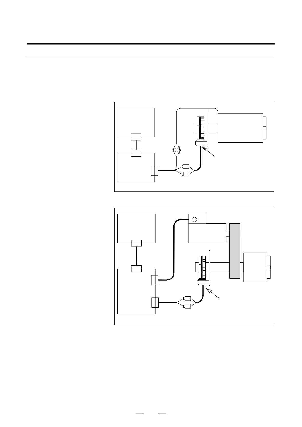
System Configuration
(1) For the α Spindle Sensor
(a) When a built-in spindle motor is used
CNC
Spindle +
OH line
built-in motor
BZ sensor (built-in sensor)
CN1
SPM
TYPE4
CN2
JY5
(b) When a motor is connected to the spindle via a belt
AC spindle motor with a
built-in MZ sensor
CNC
JY2
Spindle
SPM
TYPE4
CN1
BZ sensor (built-in sensor)
CN2
JY5
495
11. OPTION RELATED TO SPINDLE
B-65162E/03
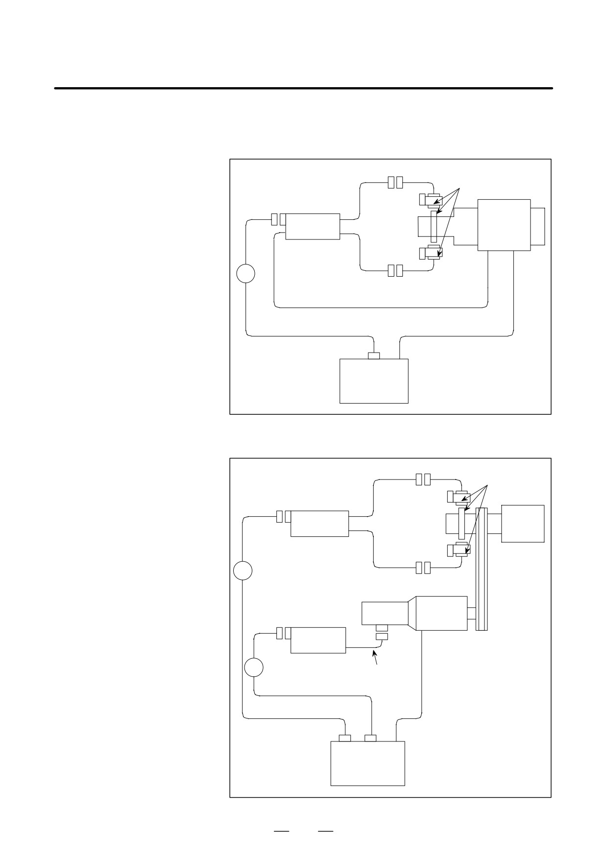
(2)
For a High-resolution Magnetic Pulse Coder
(a)
When a built-in spindle motor is used
CN0
Main detector unit
CN2
Built-in
Preamplifier
spindle
Spindle
motor
CN1
K18
OH signal line
Position and velocity feedback
Power line
JY5
Spindle
amplifier
(SPM)
Type 2
(b)
When a motor is connected to a spindle via a belt
CN0
Main
detector unit
CN2
Preamplifier
Spindle
CN1
K19
Detection
AC spindle
CN2
section
motor
Preamplifier
K18
(OH signal line included)
Velocity feedback
Power line
Position feedback
JY5
JY2
Spindle
amplifier
(SPM) Type 2
496
B-65162E/03
11. OPTION RELATED TO SPINDLE
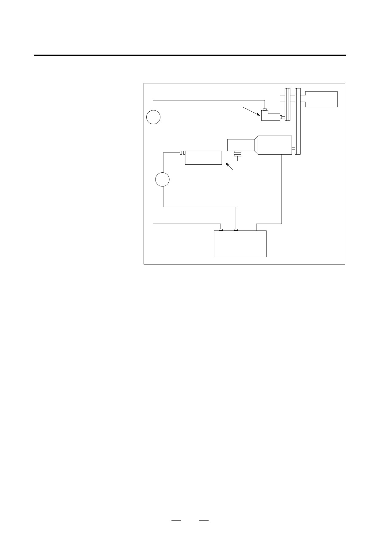
(3) For a High-resolution Position Coder
Spindle
CN1
High-resolution position coder
K31
Detection
AC spindle
CN2
section
motor
Preamplifier
(OH signal line included)
K18
Velocity feed back
Position feedback
JY2
JY4
Power line
Spindle amplifier
(SPM)
Type 2
497
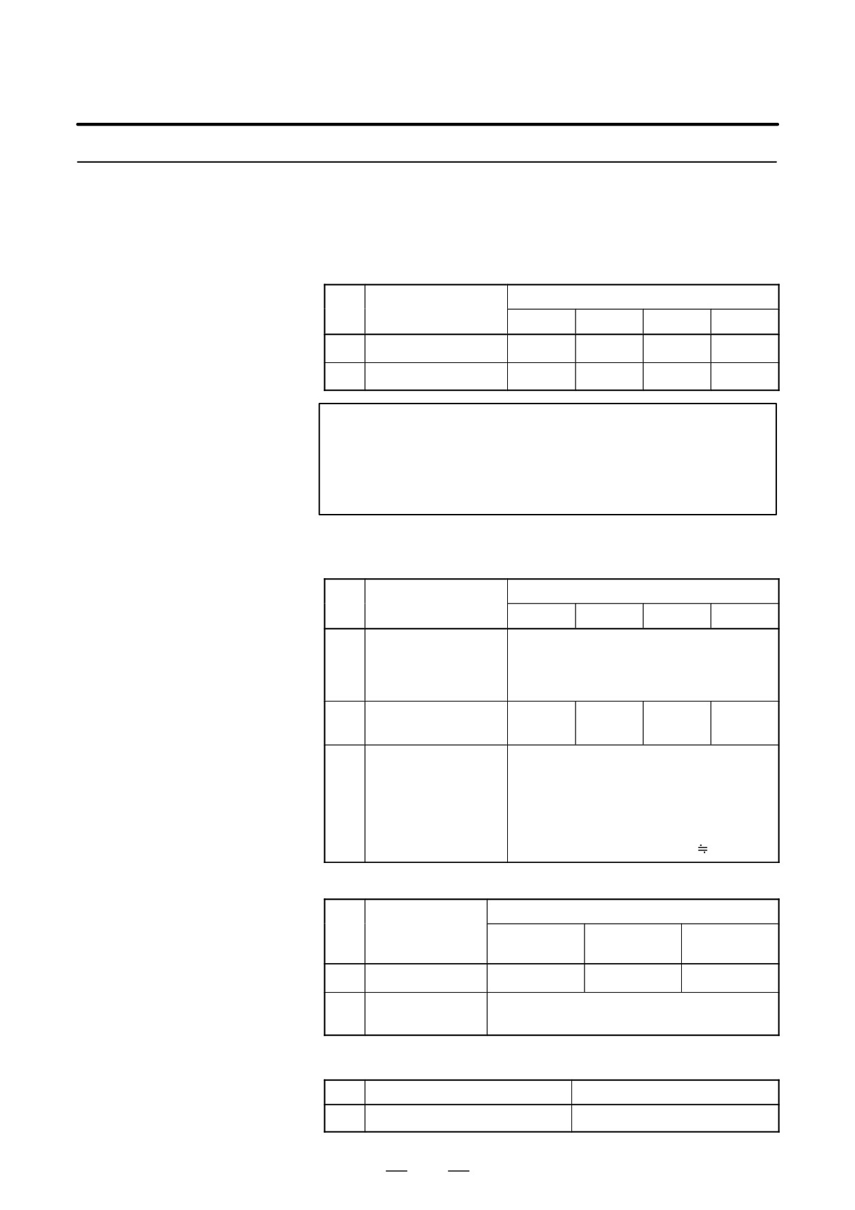
11. OPTION RELATED TO SPINDLE
B-65162E/03
11.3.3
Specifications
(1)
For the α Spindle Sensor
(a)
Detection resolution and precision of BZ sensor + internal high-resolution circuitry
BZ sensor
No
Item
128/128H
256/256H
384
512
1
Resolution [Typ.]
0.0016°
0.0008°
0.0006°
0.0004°
2
Precision [Typ.] (Note)
0.04°
0.03°
0.04°
0.04°
NOTE
It is assumed that the fluctuation of the shrink-fit section of
the spindle is within 5µm, and errors on the machine are
excluded.
(The precision depends on the mounting
accuracy of the detector.)
(Tip)
The precision is determined by the sum of previsions 1 through 3.
BZ sensor
No
Item
128/128H
256/256H
384
512
Electrical division pre-
cision of one gear tooth
1
0.015°
and gear pitch preci-
sion [Typ.]
Gear pitch circular fluc-
2
0.02°
0.01°
0.02°
0.02°
tuation precision [Typ.]
A fluctuation can be converted to a precision
according to the following formula:
Precision (°) = Vibration (mm)
360 (°)/gear
Machine side shaft fluc-
3
circumference (mm)
tuation precision [Typ.]
Example: When there are 256 teeth and a fluc-
tuation of 0.005 mm
Precision = 0.005
360/103.2/π
0.005°
(b)
Detection resolution and precision of MZ sensor + internal high-resolution circuitry
BZ sensor
No.
Item
α0.5 motor
α1 to α3 mo-
α6 motor or
(64 teeth)
tor (128 teeth)
up (256 teeth)
1
Resolution [Typ.]
0.0032°
0.0016°
0.0008°
The precision depends on the detector of (1)-(a)
2
Precision [Typ.]
mounted onto the spindle.
(2)
For a High-resolution Magnetic Pulse Coder and High-resolution Position Coder
No.
Item
1
Resolution [Typ.]
0.001°
498
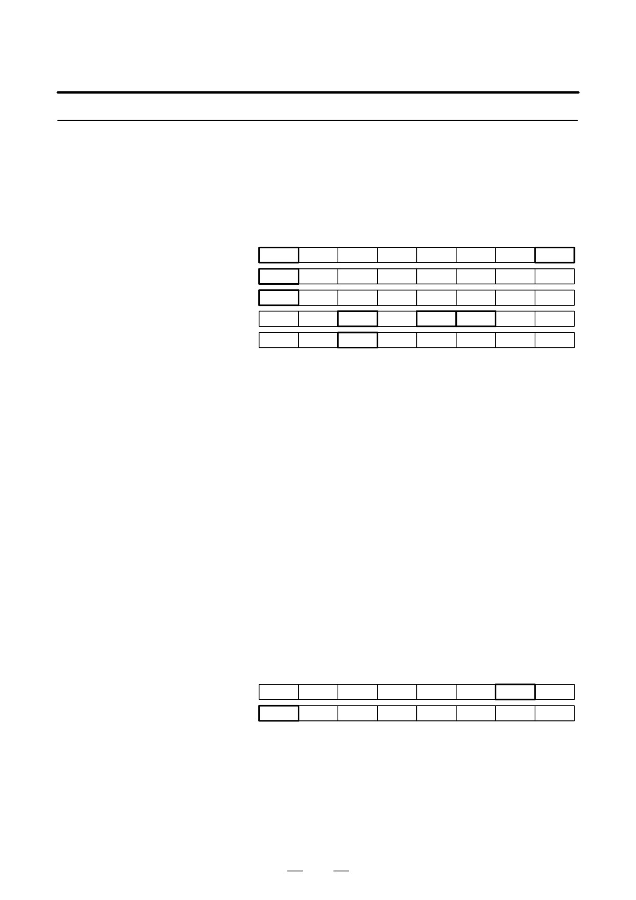
B-65162E/03
11. OPTION RELATED TO SPINDLE
11.3.4
DI and DO Signals
(1)
DI Signal (PMC to CNC)
(a)
Signal Addresses
FS0
FS15
FS16
#7
#6
#5
#4
#3
#2
#1
#0
CON(M)
COFF(T)
G123
CON(T/M)
G027
SCTR1, 2 .
G67, G71 . .
MRDYA
ORCMA
SFRA
SRVA
CTH1A
CTH2A
TLMHA
TLMLA
G229
G227
G070
RCHA
RSLA
INTGA
SOCNA
MCFNA
SPSLA
*ESPA
ARSTA
G230
G226
G071
This signal switches between the spindle rotation control mode and Cs
contouring control mode.
Before switching from the Cs contouring control mode to the spindle
rotation control mode, check that the spindle move command has
terminated. Switching from the spindle rotation control mode to the Cs
contouring control mode is enabled even when the spindle is rotating.
In this case, spindle rotation is decelerated then stopped, and the modes
are changed. For safe operation, be sure to reset the spindle speed
command (S command).
COFF
0 : Cs contouring control mode
(FS0)
1 : Spindle rotation control mode
CON
0 : Spindle rotation control mode
(FS0, FS16)
1 : Cs contouring control mode
SCNTR1, 2, ...
0 : Spindle rotation control mode
(FS15)
1 : Cs contouring control mode
(2)
DO Signal (CNC to PMC)
(b)
Signal Addresses
FS0
FS15
FS16
#7
#6
#5
#4
#3
#2
#1
#0
FSCDL
F178
F004
MCNTR1, 2 .
F67, F71 . .
This signal posts the completion of switching between the
spindle
rotation control mode and Cs contouring control mode.
FSCSL
0 : Spindle rotation control mode
(FS0C, FS16)
1 : Cs contouring control mode
MCNTR1, 2, ...
0 : Spindle rotation control mode
(FS15)
1 : Cs contouring control mode
499
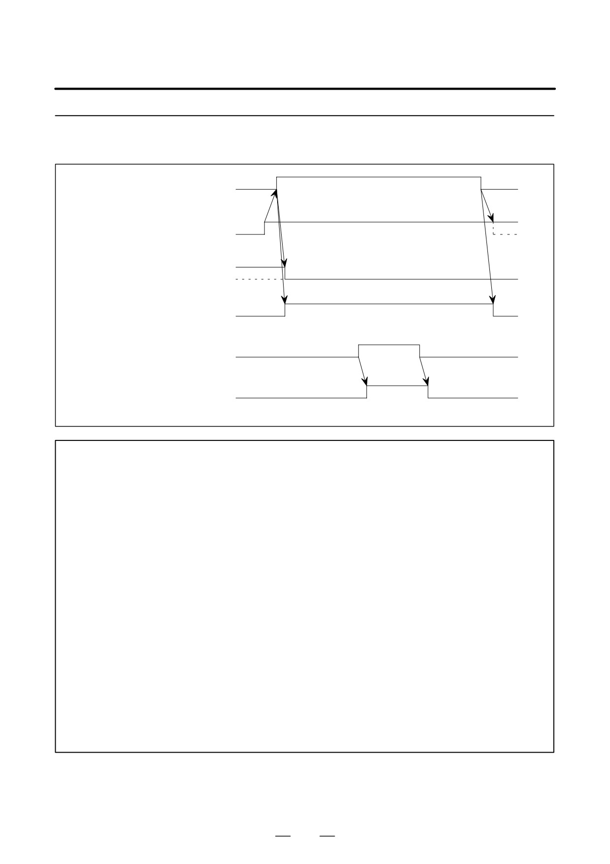
11. OPTION RELATED TO SPINDLE
B-65162E/03
11.3.5
Sample Sequence
Cs contouring control mode command
ON=1
(PMC³CNC) (Note 1)
Spindle forward rotation command
(PMC³CNC)
ON=1
(SFRA)
Spindle speed command
S0
(Sxxxx) (Note 2)
Cs contouring control mode state
(CNC³PMC) (Note
3)
ON=1
Being clamped
Spindle clamp
(Note 4)
Speed integral control disable
command
(PMC³CNC)
ON=1
(INTGA)
NOTE
1
For Series 16 :
Setting CON to 1 enters the Cs contouring control mode.
For series 15 :
Setting SCNTR to 1 enters the Cs contouring control mode.
For Series 0-TC :
Setting COFF to 0 enters the Cs contouring control mode.
For Series 0-MC :
Setting CON to 1 enters the Cs contouring control mode.
2
When specifying the Cs contouring control mode, reset the spindle speed command (S0
command) for safe operation.
3
For Series 16 :
Setting FSCSL to 1 enters the Cs contouring control mode.
For Series 15 :
Setting MCNTR to 1 enters the Cs contouring control mode.
For Series 0-C :
Setting FSCSL to 1 enters the Cs contouring control mode.
4
When the spindle is clamped after it is positioned to perform machining such as drilling in the
Cs contouring control mode, the clamp position of the spindle may deviate a little from a
specified position. If it deviates, the speed integral function works. The function attempts to
move the spindle to the specified position. As a result, excessive current may flow in the motor.
To prevent this, the speed integral function must be disabled while the spindle is being clamped.
500
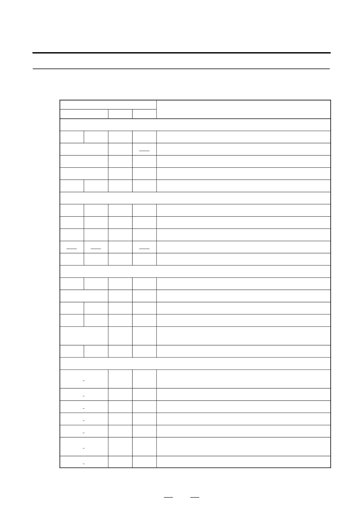
B-65162E/03
11. OPTION RELATED TO SPINDLE
11.3.6
The tables below list the parameters relating to Cs contouring control.
Refer to the Parameter Manual and each CNC manual for details.
Parameters
Parameter No.
Description
FS0
FS15
FS16
Setting of axis allocation and so forth
3rd axis
4th axis
1804#7
1023
Setting of the axis for which Cs contouring control is performed
0037#7
1804#0
Select ”High-resolution pulse coder not used.”
0037#3, 2
1815#1
1815#1
Select ”Separate pulse coder not used”.
0021#3, 2
1815#5
1815#5
Select ”Other than absolute position detector.”
0102
0103
1820
1820
Set the command multiplication to 2 (that is, x1)
Setting of an in-position width and positional deviation limit
0502
0503
1827
1826
In-position width
0506
0507
1828
1828
Limit on position error during moving
0595
0596
1829
1829
Limit on position error during stop
1830
Limit on position error during servo off
0332
0333
1832
1832
Limit on position error for feed stop
Setting of a feedrate and acceleration/deceleration time constant
0520
0521
1420
1420
Rapid feed rate
0527
1422
1422
Maximum cutting feedrate
0561
0562
1423
1423
Jog feedrate
0524
0525
1620
1620
Time constant for linear acceleration/deceleration in rapid feed
Time constant for linear acceleration/deceleration in cutting feed (op-
0635
1622
1628
tion)
0603
0604
1624
1624
Time constant for exponential acceleration/deceleration in jog feed
αSetting related to the spindle sensors (MZ sensor, BZ sensor)
Whether to use a high-resolution magnetic pulse coder. (To be set to
3001#5
4001#5
0)
3001#6
4001#6
Setting for using a position detection signal for speed detection
3001#7
4001#7
Position detector mounting direction
3000#0
4000#0
Spindle and motor rotation direction
3003#1
4003#1
Use of an MZ sensor or BZ sensor (built-in motor). (To be set to 1)
3003
4003
Position detector type setting
#7,6,4
#7,6,4
3004#1
4004#1
Whether to use a BZ sensor on the spindle side
501
11. OPTION RELATED TO SPINDLE
B-65162E/03
Parameter No.
Description
FS0
FS15
FS16
Use of the α spindle sensor Cs contour control function. (To be set to
3018#4
4018#4
1)
3719
4355
Amplitude ratio compensation (motor side)
3720
4356
Phase difference compensation (motor side)
3721
4357
Amplitude ratio compensation (spindle side)
3722
4358
Phase difference compensation (spindle side)
Setting related to the high-resolution magnetic pulse coder and high-resolution position coder
6501#5
3001#5
4001#5
Whether a high-resolution magnetic pulse coder is used (Set to 1.)
Setting for using the position signal from a high-resolution magnetic
6501#6
3001#6
4001#6
pulse coder for speed detection
6501#7
3001#7
4001#7
Mounting orientation for the high-resolution magnetic pulse coder
6504#0
3004#0
4004#0
Whether a high-resolution position coder is used
6500#0
3000#0
4000#0
Rotational direction of the spindle and motor
6503
3003
4003
Position detector type setting
#7,6,4
#7,6,4
#7,6,4
6502
3002
4002
Setting for Cs contouring control resolution (Normally, set 0, 0, 0.)
#2, 1, 0
#2, 1, 0
#2, 1, 0
Setting of a maximum spindle speed under Cs contour control
6521
3021
4021
Maximum spindle speed for Cs contouring control
Setting of a gear ratio between the spindle and motor
3056 to
4056 to
Gear ratio between spindle and motor
6556 to 6559
3059
4059
(selected by DI signals CTH1A and CTH2A)
Position gain setting
3069 to
4069 to
Position gain for the axis for which Cs contouring control is performed
6569 to 6572
3072
4072
(selected by DI signals CTH1A and CTH2A)
5609
Whether position gain is automatically set for axes for which Cs contour-
#1, 0
ing control is not performed
5609
3900 to
Position gain for axes for which Cs contouring control is not performed
6780 to 6799
#0, 1
3944
(selected by DI signals CTH1A and CTH2A)
Setting related to reference position return
6574
3074
4074
Zero point return speed in Cs contouring control
Position gain change rate for zero position return in Cs contouring con-
6592
3092
4092
trol
Direction of zero point return at the first Cs contouring control after power
6500#3
3000#3
4000#3
on
Whether the zero point return function is used for the first G00 command
0065#1
1005#0
3700#1
after switching to Cs contouring control mode
502
B-65162E/03
11. OPTION RELATED TO SPINDLE
Parameter No.
Description
FS0
FS15
FS16
Grid shift setting
6635
3135
4135
Grid shift for Cs contouring control
Rotation direction setting
Rotational direction of the spindle for + motion commands in Cs contour-
6500#1
3000#1
4000#1
ing control
6502#4
3002#4
4002#4
Rotational direction signal function for Cs contouring control
Setting of a velocity loop gain and motor voltage
6546
3046
4046
Velocity loop proportional gain for Cs contouring control
6547
3047
4047
(selected by DI signal CTH1A)
6554
3054
4054
Velocity loop integral gain for Cs contouring control
6555
3055
4055
(selected by DI signal CTH1A)
Compensation constant for external disturbance torque (acceleration
6594
3094
4094
feedback gain)
6586
3086
4086
Motor voltage for Cs contouring control (Normally, set to 100.)
Setting for control characteristics for Cs contouring control (Normally,
6516#4
3016#4
4016#4
set 0.)
6519#0
3019#0
4019#0
Whether dead zone compensation is performed in Cs contouring control
6597
3097
4097
Spindle speed feedback gain
Others
6599
3099
4099
Delay time for exciting the motor
503
11. OPTION RELATED TO SPINDLE
B-65162E/03
11.4
SPINDLE
SYNCHRONIZATION
CONTROL
On a machine having two spindles (such as a lathe), the rotational spindle
11.4.1
speed of both spindles must be the same in the following cases:
Outline
- When a workpiece on the 1st spindle is passed to the 2nd spindle while
the spindles are rotating
- When a workpiece is held by both the 1st and 2nd spindles and the
spindles are accelerated or decelerated
The rotation phase (angle) of the spindles must also be the same when a
workpiece of a special shape is passed between the spindles.
The spindle synchronization control function is used to synchronize the
two spindles in the above cases.
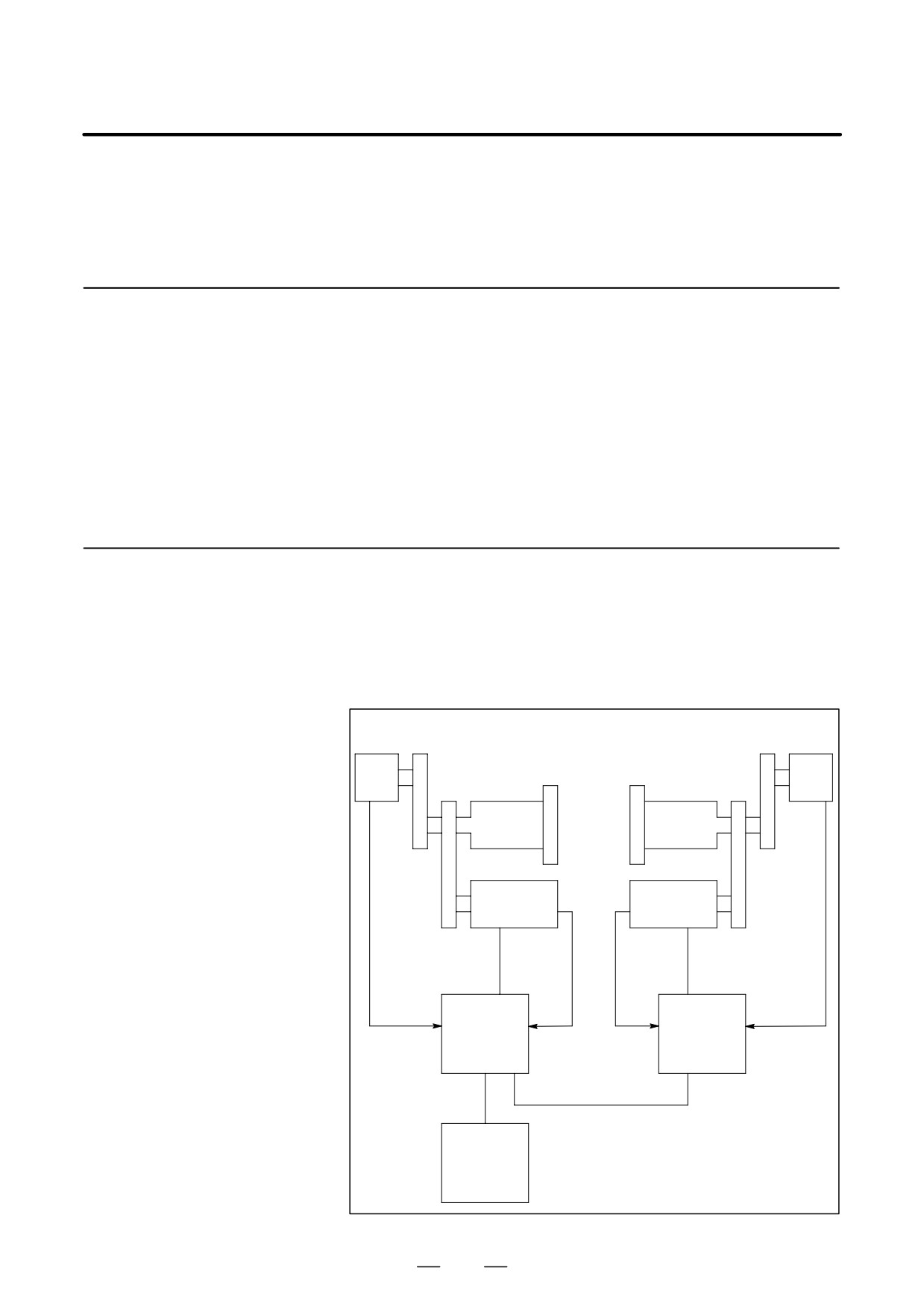
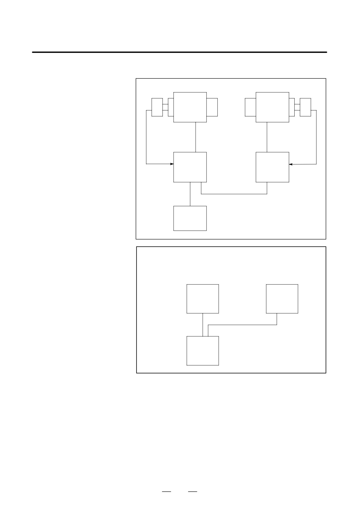
11.4.2
System Configuration
(1) αC Series Spindle
(a) When the spindle and spindle motor are connected by a belt or gears
Position
Position
Gears or timing belt
Gears or timing belt
coder
coder
1 : 1
1 : 1
1st
2nd
spindle
spindle
Con-
Spindle
Spindle
Connected
nected
motor
motor
with belt or
with
gears
belt or
Velocity
Velocity
gears
Power
Power
feedback
feedback
line
line
Position
Position
Spindle
Spindle
feedback
feedback
amplifier
amplifier
module
module
(SPM)
(SPM)
Communication
cable
Communication cable
(Note)
CNC
504
B-65162E/03
11. OPTION RELATED TO SPINDLE
(b) When built-in spindle motors are used
BZ
BZ
1st spindle
2nd spindle
sensor
sensor
Built-in
Built-in
spindle
spindle
motor
motor
Feedback
Feedback
Power
Power
signal
signal
line
line
Spindle
Spindle
amplifier
amplifier
module
module
(SPM)
(SPM)
Communication
cable
Communication cable
(Note)
CNC
NOTE
For the Series 16-TT and Series 0-TT, the CNC and
spindle amplifier modules are connected as follows:
Spindle
Spindle
amplifier
amplifier
module
module
(SPM)
(SPM)
Communication
cable
Communication cable
CNC
505
11. OPTION RELATED TO SPINDLE
B-65162E/03
(2) αC Series Spindle motor
Position
Position
coder
Gears or timing belt
Gears or timing belt
coder
1 : 1
1 : 1
First
Second
spindle
spindle
αC series
αC series
Belt or
spindle
spindle
Belt or
gear
motor
motor
gear
connection
connection
Power
Power
line
line
Position
Position
Spindle
Spindle
feedback
feedback
amplifier
amplifier
module
module
(SPMC)
(SPMC)
Communication
cable
Communication cable
CNC
506
B-65162E/03
11. OPTION RELATED TO SPINDLE
11.4.3
Explanation of Spindle
D
When the command for spindle synchronization control is issued
while the two spindles are rotating at different speeds or stopped, each
Synchronization
spindle increases or decreases its speed to the specified speed. The two
Control
spindles are then controlled in synchronization.
D
If the synchronization speed is changed after the synchronization
control of the two spindles is started, the spindles increase or decrease
their speed to the new speed. The spindles are synchronized during the
acceleration or deceleration as the speed is increased or decreased
according to the time constant specified in the parameter. When the
specified synchronization speed is 0 min-1, the two spindles stop at the
same time.
D
When the command for spindle synchronization control is issued with
the synchronization speed specified as 0 min-1 when both spindles are
stopped, the spindles rotate two or three times. After detecting the one
rotation signal of the position coder (required for synchronization
control of spindle phase), the spindles stop and enter the
synchronization control state. If the synchronization speed is changed
after the synchronous control state is established, the spindles increase
or decrease their speed to the new speed. The spindles are
synchronized during acceleration or deceleration as the speed is
increased or decreased according to the time constant specified in the
parameter.
D
To handle a workpiece with a unique shape, the spindles need to rotate
to keep the phases (angles) of rotation synchronous. When the
command for spindle phase synchronization is issued when the
spindles are already rotating in synchronization, each spindle is
adjusted to the rotation phase specified in the parameter. At this time,
the speed changes for a moment. Then the two spindles return to the
synchronization control state. Rotation phase synchronization can be
established by setting the parameters in advance so that the reference
points of the two spindles match with each other.
D
When the command for spindle phase synchronization is issued when
the spindles are controlled in synchronization at 0 min-1, each spindle
is rotated and adjusted to the phase specified in the parameter then
stops. It is similar to when the spindles are positioned in the stop state
(spindle orientation). This causes the reference points of the spindles
to match with each other
(phase synchronization).
If the
synchronization speed is changed after a workpiece with a unique
shape is held with the two spindles, the spindles increase or decrease
their speed to the new speed. The spindles are synchronized during
acceleration or deceleration as the speed is increased or decreased
according to the time constant specified in the parameter.
D
Constant surface speed control can be executed while a workpiece is
being held with the two spindles in the synchronous control state.
However, the time constant specified in the parameter is not exceeded
even when a command for a larger increment or decrement in speed
is specified.
D
Do not switch the rotation direction command (SFR/SRV) during
synchronization control.
507
11. OPTION RELATED TO SPINDLE
B-65162E/03
NOTE
Refer to the following CNC manuals as well:
Section
9.12 of FS
16i/18i/21i Connection Manual
(Function) (B-63003EN-1)
Section 9.12 of FS 16/18 Connection Manual (Function)
(B-62753EN-1)
11.4.4
DI/DO Signals
(1) DI Signals (PMC to CNC)
(a) Signal address
FS0-T FS0-TT FS15
FS16
FS16-TT
Head2
Head2
#7
#6
#5
#4
#3
#2
#1
#0
SPPHS
SPSYC
G146
G146
G038
R08I
R07I
R06I
R05I
R04I
R03I
R02I
R01I
G124
G124
G032
SSGN
R12I
R11I
R10I
R09I
G125
G125
G033
RI07
RI06
RI05
RI04
RI03
RI02
RI01
RI00
G025
RISGN
RI12
RI11
RI10
RI09
RI08
G024
SPPHS
SPSYS
G111
1st :
G229
G1429 G227
G070
G1070
SFRA
SRVA
CTH1A
CTH2A
INTGA
1st :
G230
G1430 G226
G071
G1071
2nd :
G233
G235
G074
SFRB
SRVB
CTH1B
CTH2B
INTGB
2nd :
G234
G234
G075
(b) Signal for spindle synchronization control (SPSYC)
[Function] Selects the spindle synchronization control mode.
[Operation] When the signal is set to 1, spindle synchronization control mode is
selected.
When the signal is set to 0, spindle synchronization control mode is
released.
(c) Signal for spindle phase synchronization control (SPPHS)
[Function] Selects the spindle phase synchronization mode. It becomes effective
when the signal for spindles synchronization control (SPSYC) is set to 1.
Enter this signal after the signal that indicates that synchronization
control of spindle speed is completed has been set to 1. Synchronization
control of spindle phase is started at the rising edge of this signal. Even
when this signal is set to 0, the synchronized phase does not change.
When the signal is changed again from 0 to 1, phase synchronization is
executed again.
[Operation] At the rising edge of the signal changing from 0 to 1, synchronization
control of the spindle phase begins.
508
B-65162E/03
11. OPTION RELATED TO SPINDLE
(d) Signal for integral speed control (INTGA)
[Function] Enables or disables integral speed control.
[Operation] When this signal is set to 1, integral speed control is disabled.
(Same
effect as when the integral gain of the velocity loop is set to 0.) When the
signal is set to 0, integral speed control is enabled.
When the two spindles are mechanically connected with each other, this
signal is set to 1 for both spindles so that integral speed control is
disabled.
D When a cylindrical workpiece is held with the two spindles after they
are synchronized in speed
D When a workpiece with a unique shape is held with the two spindles
after they are synchronized in phase
(2) DO Signals (CNC to PMC)
(a) Signal address
FS0-T FS0-TT FS15
FS16
FS16-TT
Head2
Head2
#7
#6
#5
#4
#3
#2
#1
#0
F178
F044
SYCAL
FSPPH
FSPSY
F111
MSPPHS
MSPSYC
SPSYAL
1st :
F281
F1481 F229
F045
F1045
SARA
RCFNA
2nd :
F285
F245
F049
(b) Signal indicating that synchronization control of spindle speed is completed (FSPSY)
[Function] Reports that synchronization control of spindle speed is completed.
[Output conditions] This signal is set to 1 when the following conditions are satisfied:
D In spindle synchronization control mode, the two spindles reach the
speed specified by the signal for specifying the spindle speed in
synchronization, and the difference between the speeds of the two
spindles is not more than the value specified in parameter 4033(FS16).
This signal is set to 0 when any of the following conditions is satisfied:
D In spindle synchronization control mode, the two spindles have not yet
reached the speed specified by the signal for specifying spindle speed
in synchronization.
D In spindle synchronization control mode, the difference between the
speeds of the two spindle is larger than the value specified in parameter
4033 (FS16).
D The spindles are not in spindle synchronization control mode.
NOTE
The signal changes from 1 to 0 when the difference in
spindle speed exceeds the value specified in parameter
4033(FS16) due to changes in the cutting load, etc.
509
11. OPTION RELATED TO SPINDLE
B-65162E/03
(c)
Signal indicating that synchronization control of spindle phase is completed (FSPPH)
[Function] Reports that synchronization control of spindle phase (control of phase
difference) is completed.
[Output conditions] This signal is set to 1 when the following conditions are satisfied:
D In spindle synchronization control mode, the two spindles reach the
speed specified by the signal for specifying the spindle speed in
synchronization, and the spindles are synchronized in phase by the
signal for spindle phase synchronization. (The difference between the
error pulses of the two spindles is not greater than the value set in
parameter 4810(FS16).)
This signal is set to 0 when any of the following conditions is satisfied:
D In spindle synchronization control mode, the two spindles have not yet
been synchronized in phase.
D In spindle synchronization control mode, the difference between the
error pulses of the two spindles is larger than the value specified in
parameter 4810 (FS16).
D The spindles are not in spindle phase synchronization control mode.
NOTE
The signal changes from 1 to 0 when the difference in the
error pulses exceeds the value specified in parameter
4810(FS16) due to changes in the cutting load, etc.
(d)
Signal for issuing an alarm detected in spindle synchronization control (SYCAL)
[Function] Reports that the difference between the error pulses of the two spindles
exceeds the value specified in the parameter for spindle synchronization
control mode. This signal is used for error handling in spindle
synchronization control.
[Output conditions] The signal is set to 1 when the following conditions are satisfied:
D In spindle synchronization control mode, the difference between the
error pulses of the two spindles exceeds the value specified in
parameter 4811(FS16), after spindle synchronization control has been
put in effect.
The signal is set to 0 when any of the following conditions is satisfied:
D The spindles are not in spindle synchronization control mode.
D In spindle synchronization control mode, the difference between the
error pulses of the two spindles is not greater than the value specified
in parameter 4811(FS16).
510
B-65162E/03
11. OPTION RELATED TO SPINDLE
11.4.5
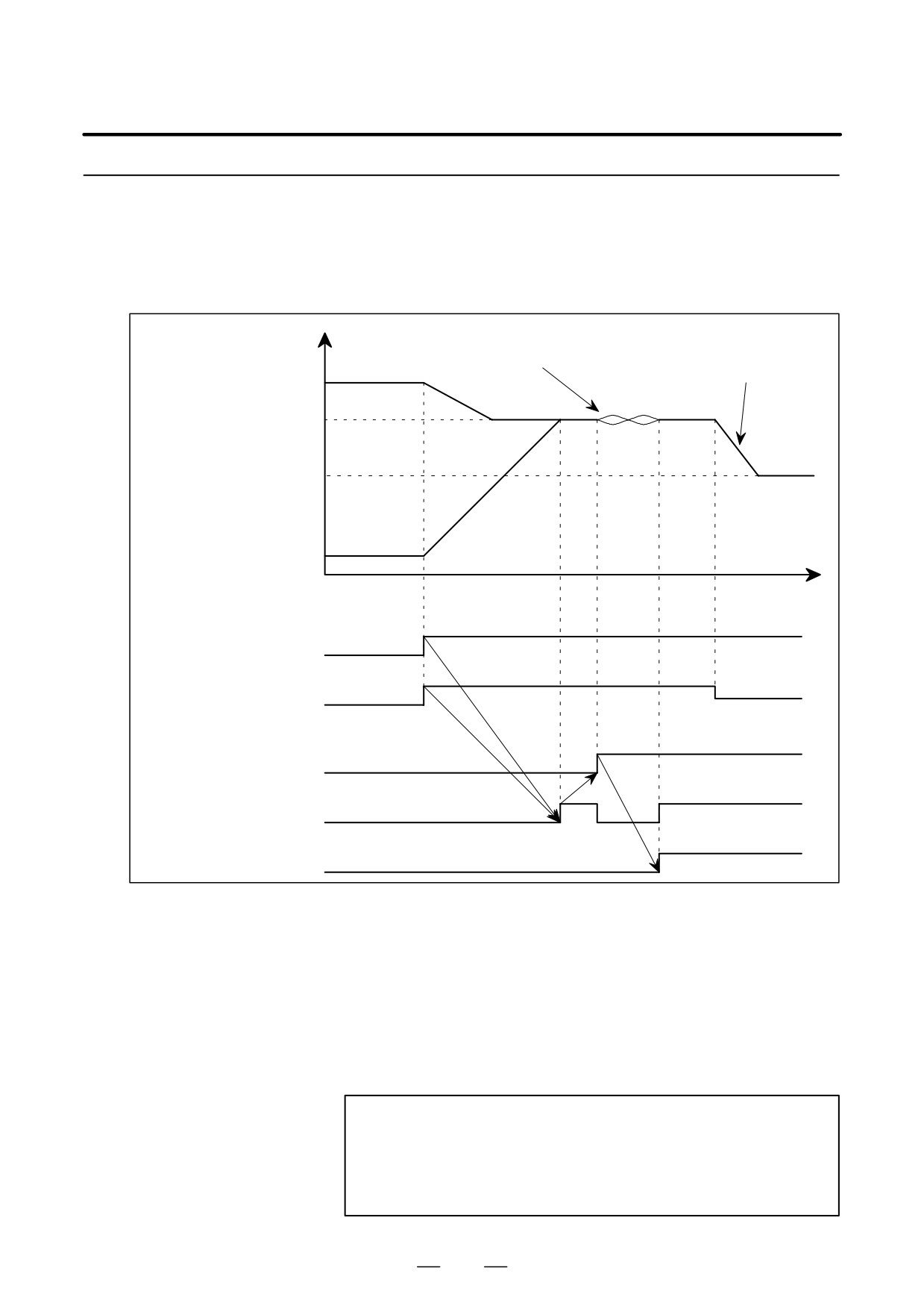
Sample Sequence
D While spindle 1 is rotating, spindle 2 is accelerated to reach the speed
of spindle 1. The phase of spindle 2 is synchronized with that of
spindle 1. Then the synchronization speed is changed, and the two
spindles increase or decrease their speed in synchronization.
Spindle speed
Acceleration/deceleration
Phase synchronization
in synchronization
Spindle 1
Synchronization
speed A
Synchronization
speed B
Spindle 2
Time
Signal for spindles synchronization
control SPSYC
Spindle
Signal for specifying the spindle
speed A
Spindle speed B
synchronization speed
R12I-R01I, RI12-00
Signal for spindle phase
synchronization control SPPHS
Signal indicating that synchronization
control of spindle speed is completed FSPSY
(Note)
Signal indicating that synchronization
control of spindle phase is completed FSPPH
Enter the signal for specifying spindle synchronization speed and set
the signal for spindle synchronization control to 1.
Wait until the signal indicating that synchronization control of spindle
speed is completed is set to 1.
Set the signal for spindle phase synchronization to 1.
Wait until the signal indicating that synchronization control of spindle
phase is completed is set to 1.
NOTE
The signal indicating that synchronization control of spindle
speed is completed is set to 0 when the signal for spindle
phase synchronization control is entered. It is changed to
1 when phase synchronization is completed.
511
11. OPTION RELATED TO SPINDLE
B-65162E/03
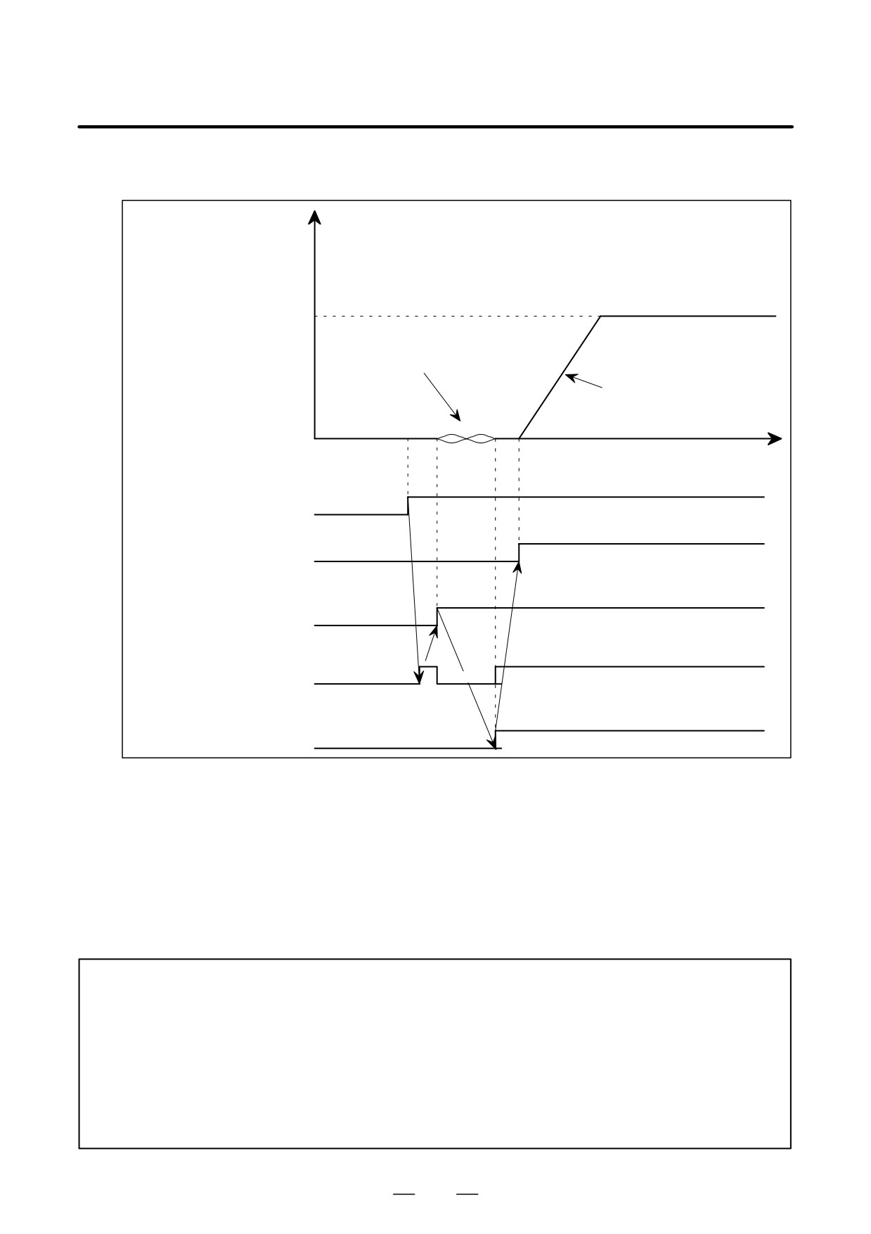
D While spindles 1 and 2 are stopped, their phases are synchronized and
their speeds are increased in synchronization.
Spindle speed
Spindles 1 and 2
Synchronization speed
Phase synchronization
Acceleration/deceleration
in synchronization
(Note 1)
Time
Signal for synchronization control
SPSYC
Signal for specifying spindle
synchronization speed
R12I-R01I, RI12-00
Signal for spindle phase
synchronization control SPPHS
Signal indicating that synchronization
control of spindle speed is completed
FSPSY
(Note 2)
Signal indicating that the synchronous
control of spindle phase is completed
FSPPH
Set the signal for specifying the spindle synchronization speed to 0 and
the signal for spindle synchronization control to 1.
Wait until the signal indicating that synchronization control of spindle
speed is completed is set to 1.
Set the signal for spindle phase synchronization control to 1.
Wait until the signal indicating that synchronization control of spindle
phase is completed is set to 1.
Enter the signal for specifying the spindle synchronization speed.
NOTE
1
When the spindle synchronization mode is switched (after power is supplied), each spindle
automatically rotates several turns to detect one-rotation signals even if the program does not
request so. If this operation causes a problem (for example, because two spindles are
connected mechanically), or spindle phase synchronization is not to be performed, the
operation can be disabled using parameters (No.4006#3 (FS16)).
2
The signal indicating that synchronization control of spindle speed is completed is set to 0 when
the signal for spindle phase synchronization control is entered. It is changed to 1 when phase
synchronization is completed.
512