FANUC SERVO AMPLIFIER a series. DESCRIPTIONS (B-65162E/03) - page 19
B-65162E/03
11. OPTION RELATED TO SPINDLE
11.7.4
External Dimensions
and Dimensions for
Mounting
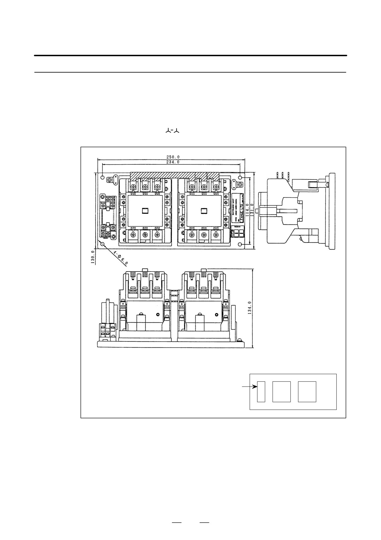
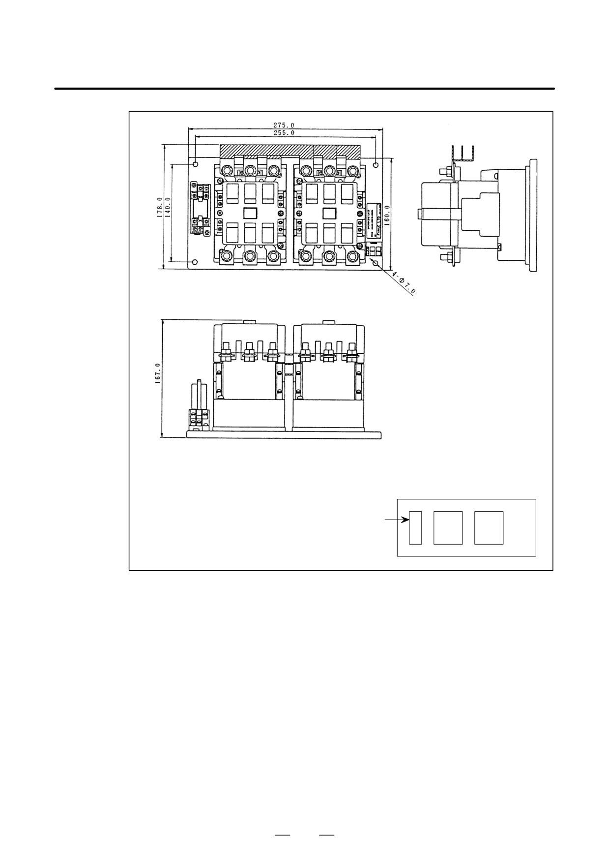
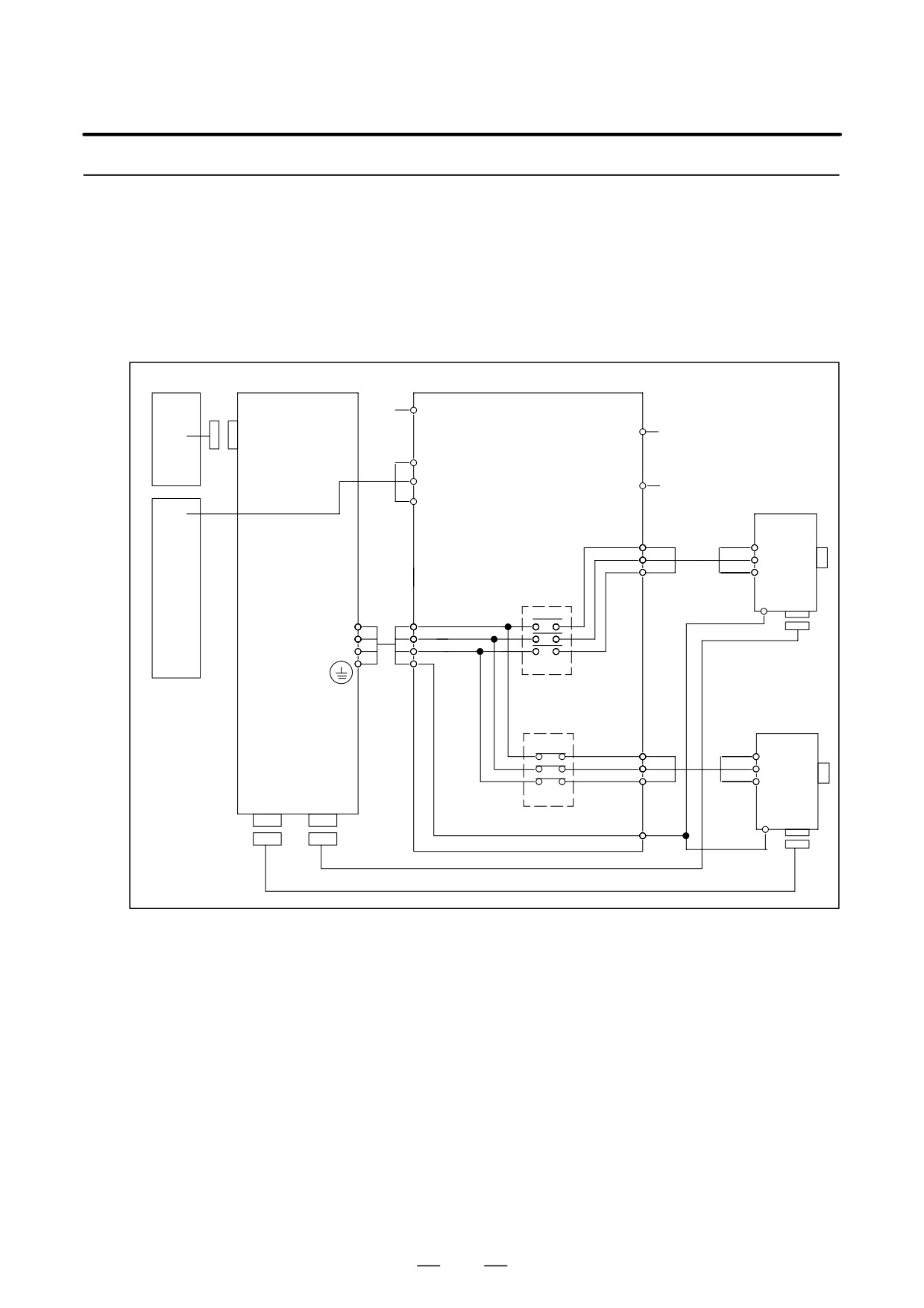
(1) External Dimensions and Dimensions for Mounting the Switching Unit for the Spindle Switching Control and
Speed Range Switching Control (Type B:
Connection)
A06B-6059-K034
Layout Drawing
RELAY
MCC1
MCC2
543
11. OPTION RELATED TO SPINDLE
B-65162E/03
A06B-6059-K036
Layout Drawing
RELAY
MCC1
MCC2
544
B-65162E/03
11. OPTION RELATED TO SPINDLE
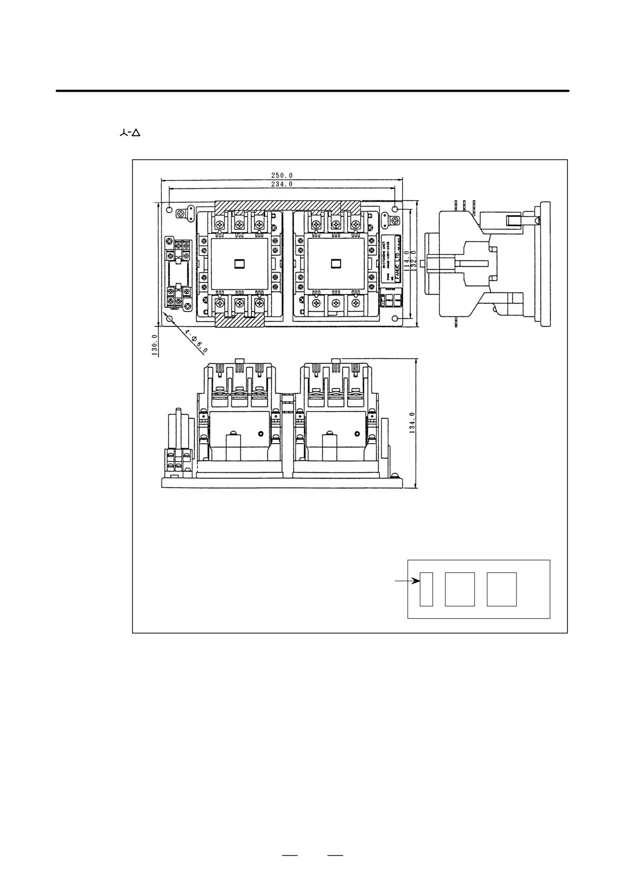
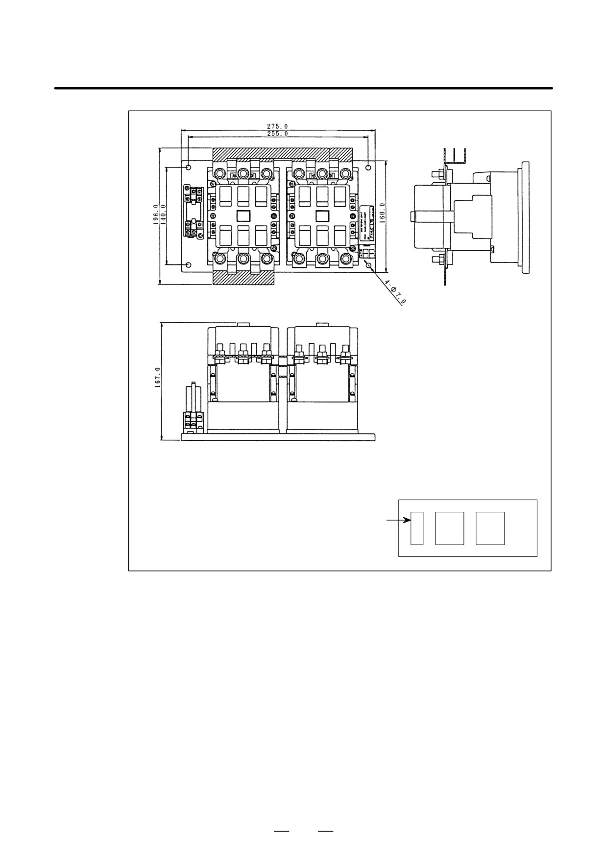
(2) Outside Dimensions and Dimensions for Mounting the Switching Unit for Speed Range Switching Control
(Type A:
Connection)
A06B-6059-K035
Layout Drawing
RELAY
MCC1
MCC2
545
11. OPTION RELATED TO SPINDLE
B-65162E/03
A06B-6059-K037
Layout Drawing
RELAY
MCC1
MCC2
546
B-65162E/03
11. OPTION RELATED TO SPINDLE
11.7.5
Connection
Complete Schematic
Drawing
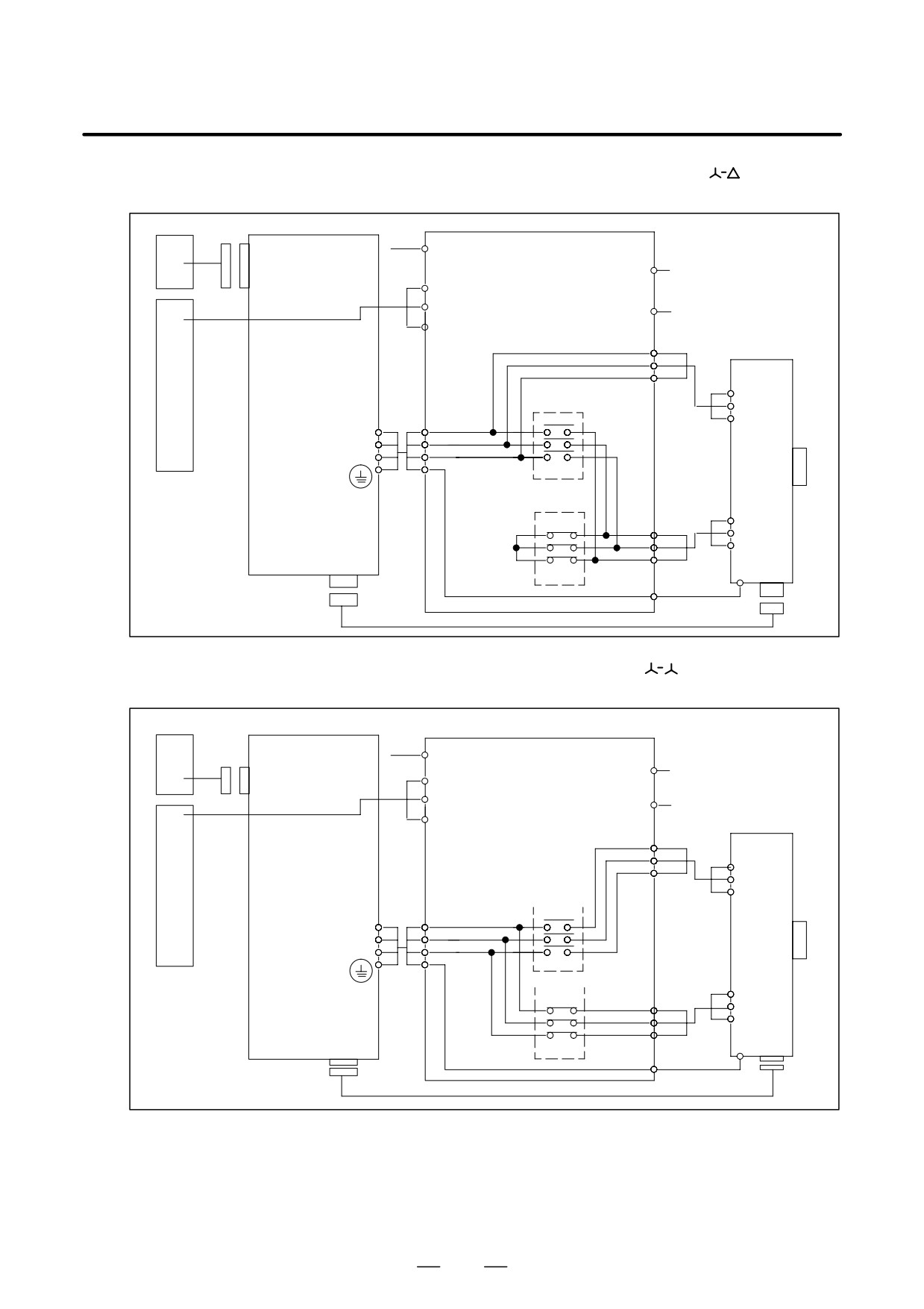
(1)
Schematic Drawing of the Switching Unit for Spindle Switching Control
Swiching unit
+24V
RYS (8)
CNC
RELAY
JA7B
SOCKET
Single-phase
(5)
200VAC
MAIN
MCC1
SPINDLE
(42)
MOTOR
Electromagnetic contactor
AC spindle
for switching power lines
2
U2
amplifier
4
V2
U2
PMC
module
6
W2
V2
W2
(SPM)
TB2
MCC2
G
U
1
2
U
V
3
4
TYPE 3
V
W
5
6
W
G
ÂÂ
SUB
ÂÂ
SPINDLE
MCC1
MOTOR
1
2
2
U1
3
4
4
V1
U1
5
V1
6
6
W1
W1
JY6
JY2
G
G
547
11. OPTION RELATED TO SPINDLE
B-65162E/03
(2) Schematic Drawing of the Switching Unit for Speed Range Switching Control (Type A:
Connection)
Swiching unit
+24V
CNC
RYS (8)
JA7B
RELAY
SOCKET (5)
Single-phase
200VAC
MCC1 (42)
Electromagnetic contactor
for switching power lines
AC spindle
2
U
amplifier
4
V
PMC
module
6
W
(SPM)
U
MCC2
TB2
V
U
2
1
W
U
V
4
3
V
W
6
5
AC
W
G
spindle
ÂÂ
motor
MCC1
ÂÂ
X
2
1
1
X
4
3
3
Y
Y
6
5
5
Z
Z
JY2
G
G
(3) Schematic Drawing of the Switching Unit for Speed Range Switching Control (Type B:
Connection)
Swiching unit
+24V
RYS (8)
RELAY
CNC
JA7BA
SOCKET (5)
Single-phase
200VAC
MCC1 (42)
AC spindle
2
U2
amplifier
Electromagnetic contactor
4
V2
PMC
6
U2
module
for switching power lines
W2
V2
(SPM)
TB2
W2
MCC2
U
1
2
U
AC
V
3
4
V
spindle
W
5
6
W
G
motor
ÂÂ
MCC1
ÂÂ
U1
1
2
U1
V1
3
4
V1
W1
5
6
W1
JY2
G
G
548
B-65162E/03
11. OPTION RELATED TO SPINDLE
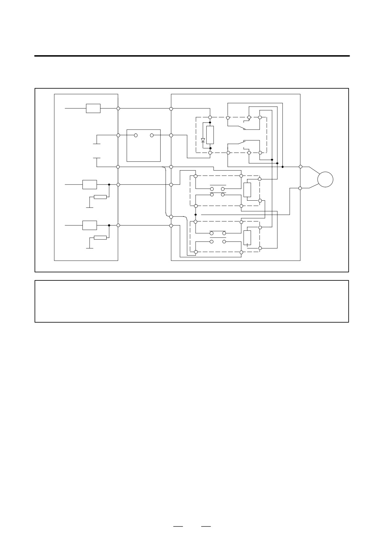
(4) Detailed Diagram of Connections between the PMC and the Switching Unit
Power-line
Switching unit
PMC
switching signal
RYS (7)
DV
7
5
3
1
Switching
unit control
RYS (8)
signal
Relay
0V
+24V
0V
Regulated
+24V power
+24
2
RYS
supply
8
6
4
Mcc1 (14)
(5)
13
14
A1
Supplementary
RV
contact A
Mcc1 (42)
Magnetic contact
Mcc1
MCC1
200VAC
status signal for
(13)
Supplementary
A
the low-speed
contact B
2
Mcc
42
range or the sub
0V
41
(42)
spindle
32
31
Mcc
Supplementary
A1
RV
(41)
contact B
Magnetic contact
status signal for
MCC2
the high-speed
Supplementary
A
range or the main
contact A
0V
42
41
2
spindle
NOTE
1
Connect the PMC to the switching unit at the screw terminals of the electromagnetic contactor
and relay socket with screws.
2
For information on interface signals, see sections 11.5 and 11.6.
549
11. OPTION RELATED TO SPINDLE
B-65162E/03
11.7.6
Caution in Use
D Install the switching unit under the same conditions as for a spindle
amplifier.
Conditions for installing the switching unit
- Ambient temperature:
0 to 55°C for the unit
0 to 45°C for the cabinet
- Ambient humidity: 90%RH or less, no condensation
- Vibration : 0.5 G or less during operation
- Ambient air : Corrosive, conductive mist or water drops must not
come into direct contact with electronic circuits.
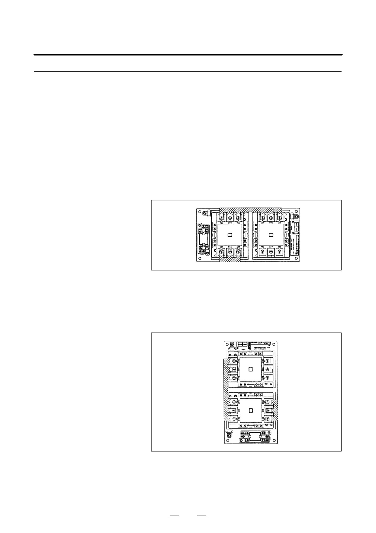
D Install the switching unit according to Fig. 11.7.6 (a). An inclination
of 15 degrees is permitted in the right, left, front, and back.
Fig.11.7.6 (a) Standard Installation (for A06B-6078-K035)
D It may be necessary to install the unit on its side as shown in Fig. 11.7.6
(b), due to wiring or space limitations. The characteristics of the
electromagnetic contactor will not be affected, however, the
mechanical life of the unit and the number of times the contactor can
be opened and closed will be decreased.
Fig.11.7.6 (b) Non-standard Installation (for A06B-6078-K035)
550
B-65162E/03
11. OPTION RELATED TO SPINDLE
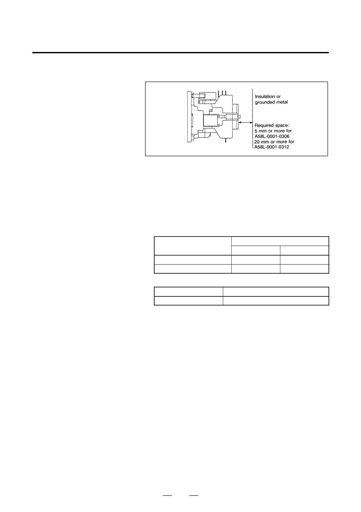
D Leave enough space to prevent arc from affecting other units, as shown
in Fig. 11.7.6 (c).
Fig.11.7.6 (c) Required Space
D If an electromagnetic contactor is installed incorrectly, contacts may
jump at power on or its life may be decreased. If a cable is not
connected to the contactor securely, the connected part may generate
heat or the cable may loosen and come off, resulting in a serious
accident.
- Tightening torque
z Electromagnetic contactor
Tightening torque (kg · cm)
Item
A58L-0001-0306
A58L-0001-0312
MCC main terminal
62.0 (M6.0)
84.0 (M8.0)
MCC supplementary terminal
14.0 (M3.5)
14.0 (M3.5)
z Relay socket
Item
Tightening torque (kg · cm)
Relay socket
14.0 (M3.5)
551
11. OPTION RELATED TO SPINDLE
B-65162E/03
11.8
DIFFERENTIAL
SPINDLE SPEED
CONTROL
11.8.1
Differential spindle speed control relatively controls the rotation speed of
spindle 2 for the rotation speed of spindle 1.
Outline
NOTE
This function is not available for αC series.
The Rigid Tap movement can be done without stopping the rotation of
11.8.2
work (Spindle 1). So far, to do the Rigid Tap, it was necessary to stop
Characteristic
spindling it temporarily. It is possible to shorten the time by using this
function.
11.8.3
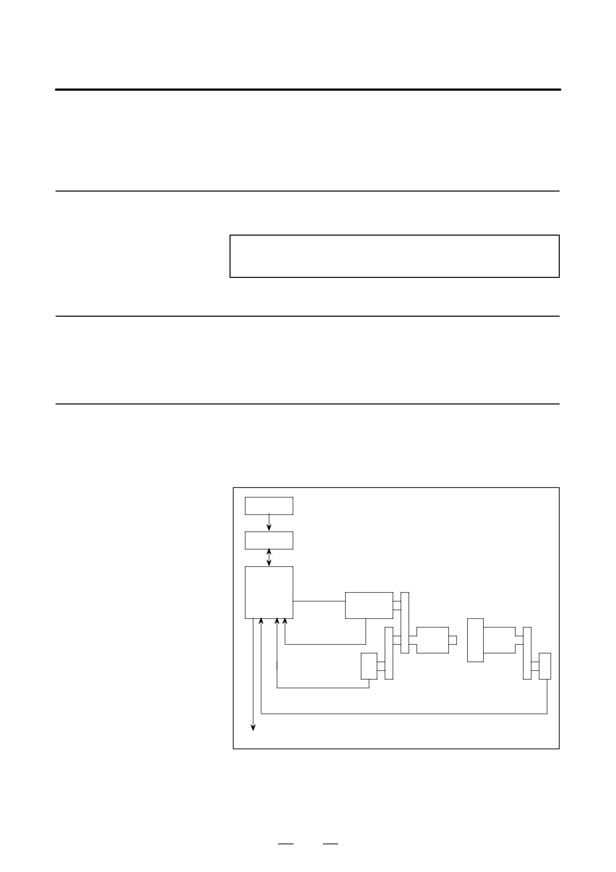
Configuration and
Ordering Number
Configuration
PMC
Command for differential speed mode
CNC
Communication cable
Spindle
amplifier
module
Power line
(SPM)
Spindle
TYPE 3
Spindle 1
motor
Spindle 2
JY8 JY4
(for workpiece)
(on tool side)
JX4
JY2
Velocity feedback
Position coder
feedback signal
for spindle 2
Position coder
Position coder feedback signal for spindle 1
Position coder signal output for spindle 1
552
B-65162E/03
11. OPTION RELATED TO SPINDLE
11.8.4
Specifications of the
D The position coder signal for spindle 1, input to connector JY8, is
output from connector JX4.
Position Coder Signal
D High resolution magnetic pulse coder can’t be used when you use this
differential speed control function.
D Unite position coders by 1:1 against Spindle 1
D Use the position coders of the signal 1024p/rev or 512p/rev output.
(set with parameters)
D At the differential speed Rigid Tap, a rotating speed of spindle 2
(commanded speed at Rigid Tap + rotating speed of Spindle 1) must
not be over the maximum speed range.
In the range where the rotating speed is high, the output torque of the
motor becomes small generally. For that set acceleration/deceleration
time constant at the Rigid Tap more largely than usually.
D Refer to the item of the Rigid Tap of the operator’s manual of CNC for
use concerning the Rigid Tap.
11.8.5
Signal Explanation
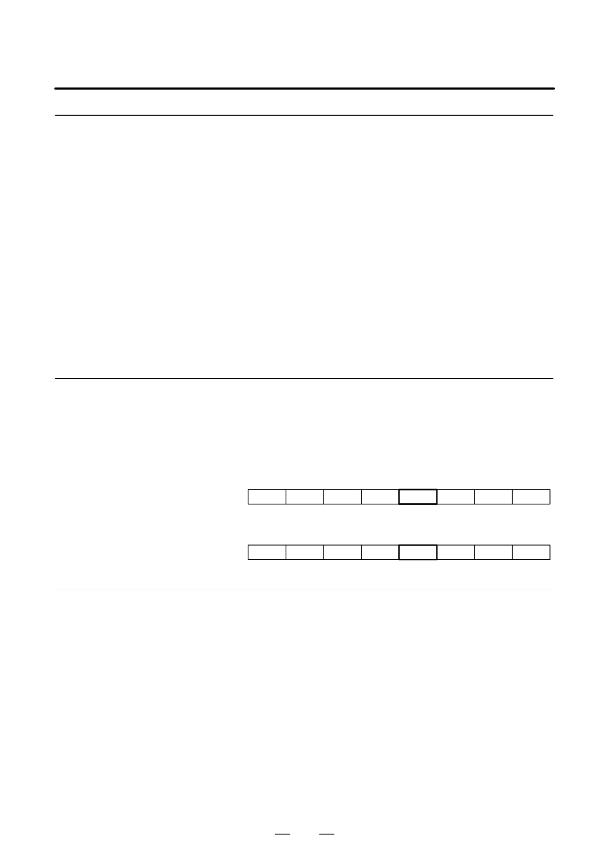
(1) DI Signal (PMC to CNC)
First spindle control input signal
FS0
FS15
FS16
#7
#6
#5
#4
#3
#2
#1
#0
G231
G229
G072
RCHHGA
MFNHGA
INCMDA
OVRA
DEFMDA
NRROA
ROTAA
INDXA
Second spindle control input signals
FS0
FS15
FS16
#7
#6
#5
#4
#3
#2
#1
#0
G235
G237
G076
RCHHGB
MFNHGB
INCMDB
OVRB
DEFMDB
NRROB
ROTAB
INDXB
Differential speed mode
command DEFMDA
[FUNCTION] Differential speed mode is specified for the spindle amplifier.
0: Normal mode
1: Differential speed mode
[MOVEMENT] While this signal is set to 1, the second spindle is controlled in differential
speed mode. In differential speed mode, the second spindle is controlled
so that its speed is the sum of the specified speed of the second spindle
and that of the first spindle.
553
11. OPTION RELATED TO SPINDLE
B-65162E/03
11.8.6
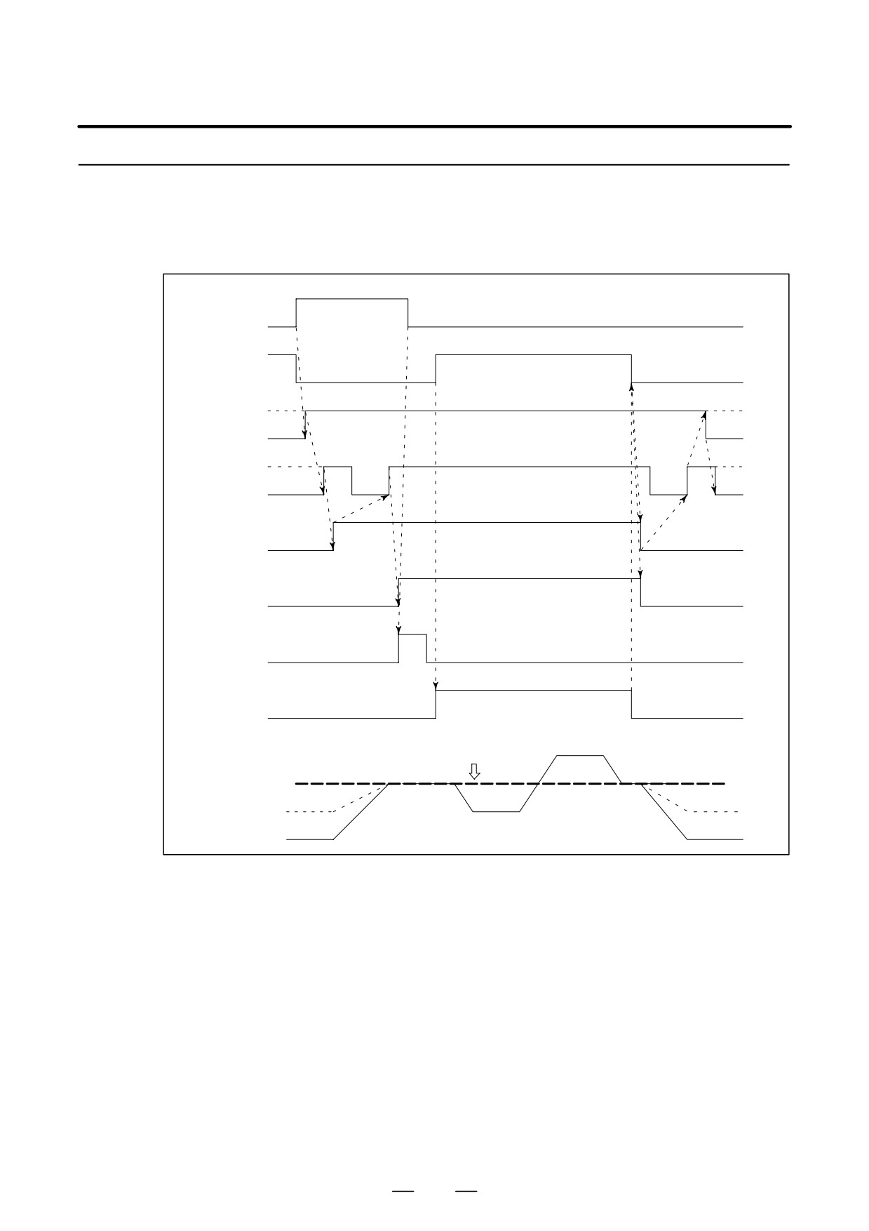
Example of Sequence
of Differential Speed
Rigid Tap
M29S-;
G84X.. R.. ;
G80;
M29
(³PMC)
ENB
(PMC)
SFR
(CNC²)
SARS
(³PMC)
Speed arrival
DEFMOD
(CNC²)
Differential speed mode
RGTAP
(CNC²)
FIN
(CNC²)
Position Loop
Rotating speed of Spindle 1
(Bold Dashed)
Not 0 min-1
Not 0 min-1
Rotating speed of
Spindle 2
0 min-1
When differential speed mode is commanded to Spindle 2, Spindle 2
is accelerated to reach to a speed of Spindle 1. (Solid line indicates the
case that the command of rotating speed of Spindle 2 is 0 min-1)
After confirming that Spindle 2 reaches to the speed of Spindle 1, Go
to rigid Tap sequences.
Doing Differential speed Rigid Tapping.
After finishing Rigid Tap sequences, in the case of command of speed
of Spindle 2 is 0 min-1, Spindle 2 is stopped. (Solid line) If command
of Spindle 2 is not 0 min-1, Spindle 2 is accelerated /decelerated to
reach to the command. (Dashed line)
554
B-65162E/03
11. OPTION RELATED TO SPINDLE
NOTE
1
When applying differential speed control to rigid tapping
(differential speed rigid tapping), ensure that the sum of the
speed specified for rigid tapping and that of the first spindle
does not exceed the maximum speed of the second spindle.
2
The output torque of a motor generally decreases in high
speed areas. So, a larger acceleration/deceleration time
constant must be set for rigid tapping.
3
For the method of rigid tapping, refer to the CNC manual.
11.8.7
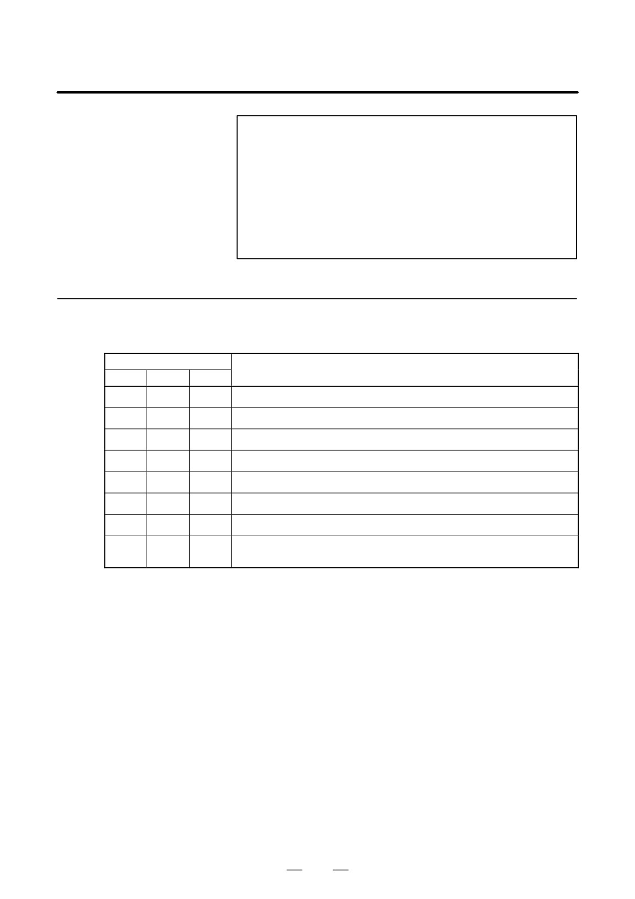
The table below lists the parameters related to the differential speed
control function. Refer to the Parameter manual for details.
Parameters
Parameter No.
Description
FS0
FS15
FS16
6500#5
3000#5
4000#5
Whether the differential speed control function is used (Set to 1.)
6500#6
3000#6
4000#6
Setting of the differential speed direction
6500#0
3000#0
4000#0
Rotational direction of the spindle and motor
6500#2
3000#2
4000#2
Mounting orientation of the position coder
6500#7
3000#7
4000#7
Setting of the number of position coder feedback pulses for spindle 1.
6501#2
3001#2
4001#2
Whether the position coder signal is used
6502#5
3002#5
4002#5
Setting of the rotation direction signal function in the servo mode
6503
3003
4003
Setting of the position coder signal
#7, 6, 4
#7, 6, 4
#7, 6, 4
555
12. DETECTORS FOR THE SPINDLE
B-65162E/03
DETECTORS FOR THE SPINDLE
12
556
B-65162E/03
12. DETECTORS FOR THE SPINDLE
12.1
POSITION CODERS
12.1.1
α Position Coder
(1) Name and Drawing Number
Table.12.1.1 (a) Name and Drawing Number
Name
Drawing No.
Remarks
Mounted with j68 flange,
α position coder
A860-0309-T302
10,000 min-1
(2)
Absolute Maximum Ratings
Table.12.1.1 (b) Absolute Maximum Ratings
Item
Specifications
Power supply voltage
-0.5V to +7.0V
Operating temperature
0_C to +50_C
Humidity
95% RH or less
(3)
Electrical Specifications
Table.12.1.1 (c) Electrical Specifications
Item
Specifications
Power supply voltage
5V"5%
Current consumption
350mA or less
PAE,*PAE,PBE,*PBE
1,024 pulses/rev
Output signal
PSE,*PSE
1 pulse/rev
(4)
Mechanical Specifications
Table.12.1.1 (d) Mechanical Specifications
Item
Specifications
Input axis inertia
1
10-3kg cm s2 or less
Input axis start torque
1,000g cm or less
Operating
10kg
Radial load
Stopped
20kg
Allowable input axis
load
Operating
5kg
Thrust load
Stopped
10kg
Maximum speed
10,000min-1
Dust-proof and drip-proof structure (equivalent to
Structure
IP55: when a waterproof connector is fitted)
Tolerable vibration ac-
10G (10 to 500Hz)
celeration/deceleration
Weight
Approx. 750kg
557
12. DETECTORS FOR THE SPINDLE
B-65162E/03
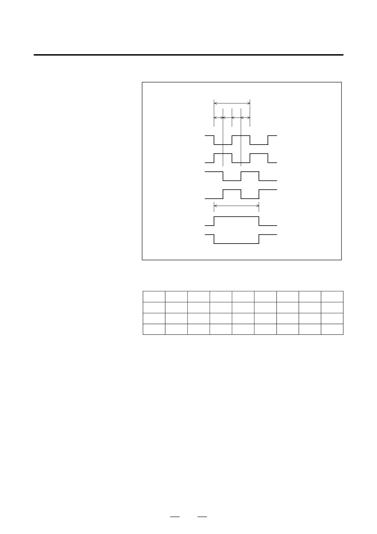
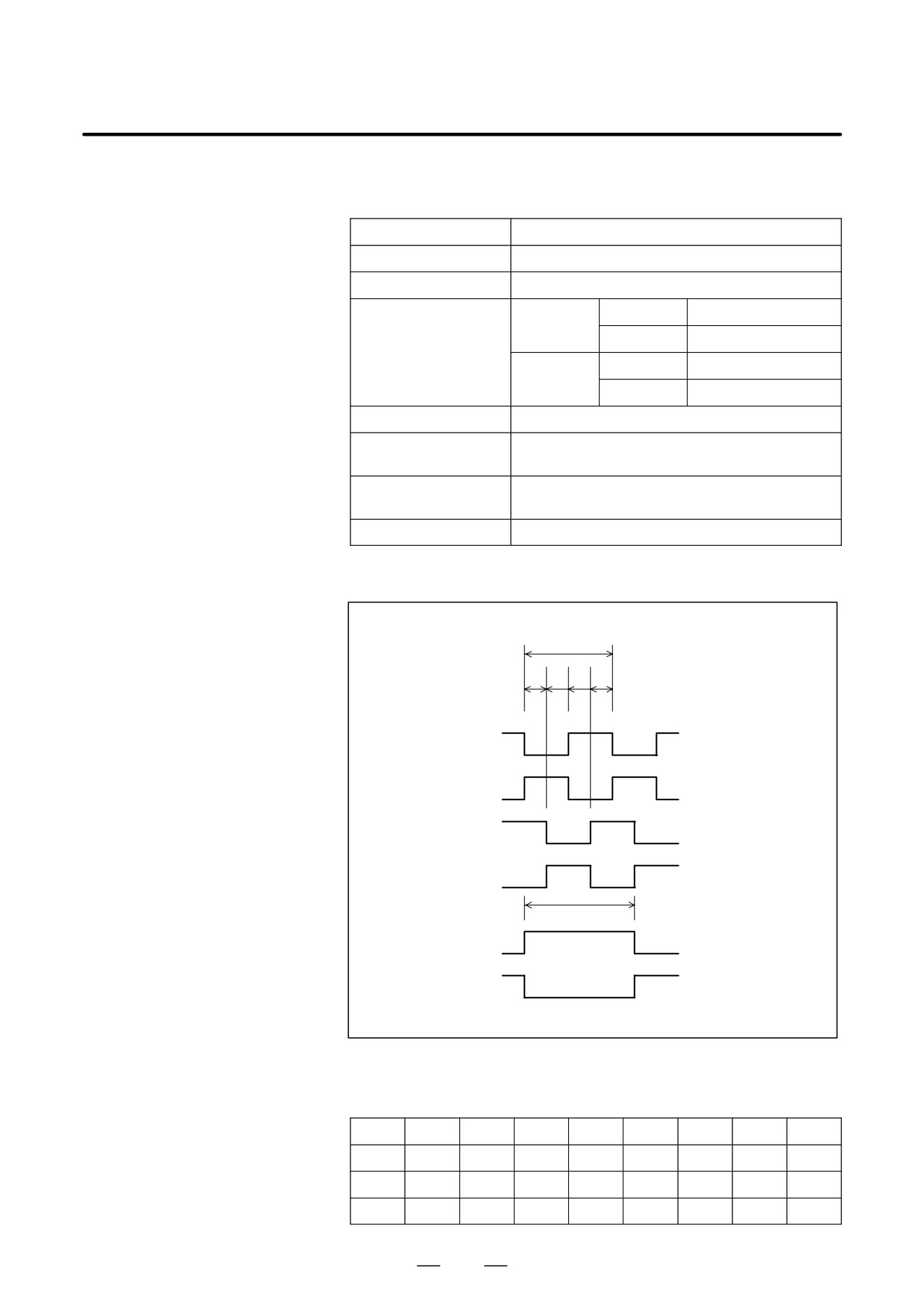
(5) Phase Relationship of Signals (Timing Chart)
T
a
b
c
d
a, b, c, d=T/4"T/10
PAE
*PAE
PBE
*PBE
e
Txex2.3T
PSE
*PSE
(6) Output pin configuration
Table.12.1.1 (e) Output Pin Configuration
A
B
C
D
E
F
G
H
J
PAE
PSE
PBE
+5V
K
L
M
N
P
R
S
T
0V
*PAE
*PSE
*PBE
558
B-65162E/03
12. DETECTORS FOR THE SPINDLE
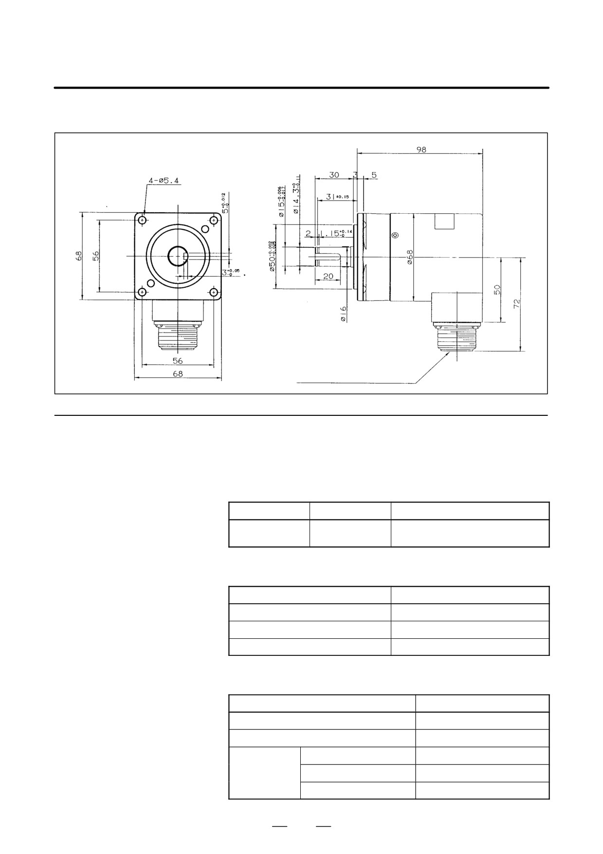
(7) Outline Drawing
MS connector:
MS3102A-20-29P
12.1.2
High-resolution
Position Coder
(1) Name and Drawing Number
Table.12.1.2 (a) Name and Drawing Number
Name
Drawing No.
Remarks
High-resolution
A860-0319-T002
Mounted with j68 flange,8,000 min-1
position coder
(2) Absolute Maximum Ratings
Table.12.1.2 (b) Absolute Maximum Ratings
Item
Specifications
Power supply voltage
-0.5V to +7.0V
Operating temperature
0_C to +50_C
Humidity
95% RH or less
(3) Electrical Specifications
Table.12.1.2 (c) Electrical Specifications
Item
Specifications
Power supply voltage
5V"5%
Current consumption
350mA or less
PAE,*PAE,PBE,*PBE
1,024 pulses/rev
Output signal
PSE,*PSE
1 pulse/rev
AP,XAP,BP,XBP
3,000 λ/rev
559
12. DETECTORS FOR THE SPINDLE
B-65162E/03
(4) Mechanical Specifications
Table.12.1.2 (d) Mechanical Specifications
Item
Specifications
Input axis inertia
1
10-3kg cm s2 or less
Input axis start torque
1,000g cm or less
Operating
10kg
Radial load
Stopped
20kg
Allowable input axis
load
Operating
5kg
Thrust load
Stopped
10kg
Maximum speed
8,000min-1
Dust-proof and drip-proof structure (equivalent to
Structure
IP55: when a waterproof connector is fitted)
Tolerable vibration ac-
10G (10 to 500Hz)
celeration/deceleration
Weight
Approx. 750kg
(5) Phase Relationship of Signals (Timing Chart)
T
a
b
c
d
a, b, c, d=T/4"T/10
PAE
*PAE
PBE
*PBE
e
Txex2.3T
PSE
*PSE
(6) Output pin configuration
Table.12.1.2 (e) Output Pin Configuration
A
B
C
D
E
F
G
H
J
AP
BP
*PBE
XAP
XBP
PSE
*PSE
SS
+5V
K
L
M
N
P
R
S
T
+5V
*PAE
PAE
0V
PBE
0V
560
B-65162E/03
12. DETECTORS FOR THE SPINDLE
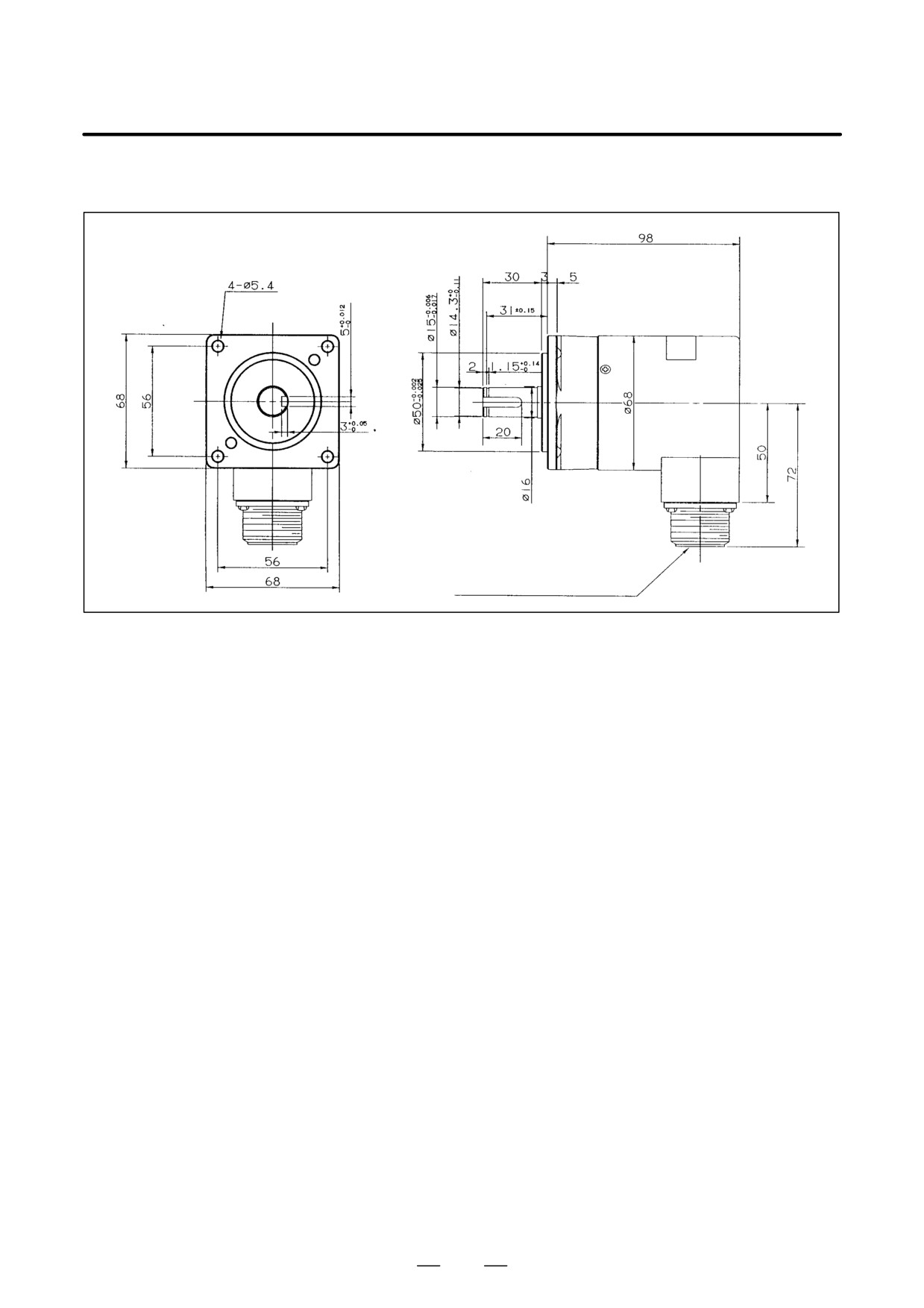
(7) Outline Drawing
MS connector:
MS3102A-20-29PW
561
12. DETECTORS FOR THE SPINDLE
B-65162E/03
12.1.3
Mounting Conditions
(a) Method of connection
and Notes
There are two methods of connecting an α position coder or
high-resolution position coder with the spindle.
(1) Connecting a position coder to the back of the spindle with a flexible
joint
This method conveys the rotation of the spindle precisely to the
position coder, so that the positioning precision of the position coder
is high. However, this method imposes a restriction on the location
of the installation. So, some modifications to the mechanical section
may become necessary.
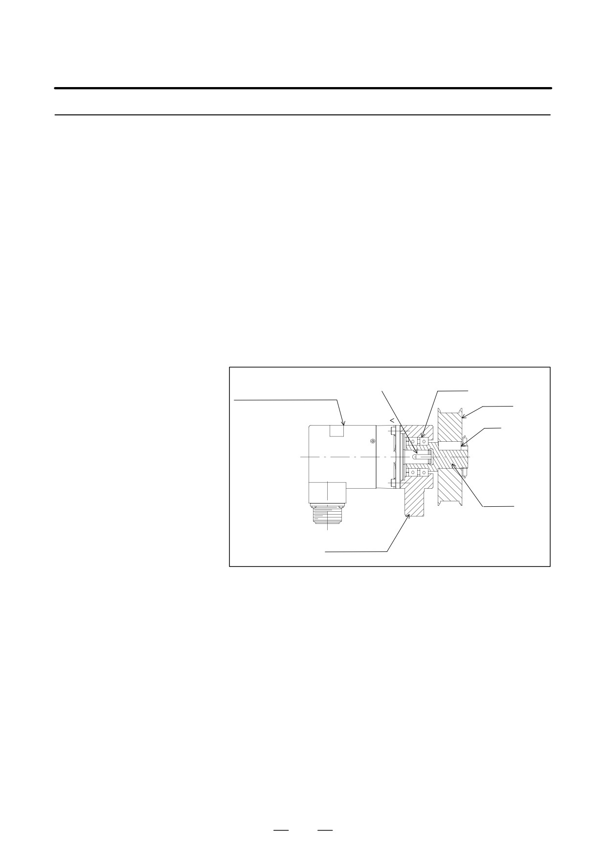
(2) As shown below, fit the shaft for holding the pulley onto the shaft of
the position coder, and hold the shaft with double bearings. Thus, the
pulley of the position coder is connected to the pulley mounted on the
spindle via a timing belt.
α position coder or high-
Bearing
Key
resolution position coder
Pulley
Key
Shaft
Mounting plate
This connection method is generally used to connect a conventional
position coder to the spindle. When using this method, note the points
below.
1) If there is any play between the shaft for holding the pulley and the
shaft of the position coder, fretting can occur on the position coder
shaft, and the key can become loose, thus resulting in degraded
precision of the position coder positioning. So, fit the components
together accurately to ensure that there is no play between the position
coder shaft and shaft holding the pulley, or between the key and key
groove.
2) If the axis center of the position coder shaft is not aligned with the axis
center of the circumference of the position coder pulley, or if the axis
center of the spindle is not aligned with the axis center of the pulley
fitted onto the spindle, the positioning precision of the spindle
degrades in proportion to the magnitude of the eccentricity. So,
minimize these eccentricities.
562
B-65162E/03
12. DETECTORS FOR THE SPINDLE
(b) Shock
The position coders are precision detectors. So, be careful to protect
the position coders from shock.
(c) Atmosphere
The position coders conform to protection class IP55. However, this
class specifies short-term performance. So, ensure that the position
coders are not exposed to coolant or lubricant, and that oil does not
build up on the position coders. If a position coder is exposed to
coolant or lubricant, place a protection cover over the position coder.
563
12. DETECTORS FOR THE SPINDLE
B-65162E/03
12.2
BZ SENSOR
(1) Names and Drawing Numbers
Table.12.2 (a) Names and Drawing Numbers
Remarks
Name
Drawing No.
Gear
Number of teeth
Maximum speed
Inner diameter
Outer diameter
BZ sensor 128
A860-0392-T012
128
20,000min-1
φ40
φ52
BZ sensor 128H
A860-0392-T082
128
50,000min-1
φ40
φ52
BZ sensor 256
A860-0392-T011
256
15,000min-1
φ82
φ103.2
BZ sensor 256S
A860-0392-T014
256
15,000min-1
φ88
φ103.2
BZ sensor 236H
A860-0392-T081
256
30,000min-1
φ82
φ103.2
BZ sensor 384
A860-0392-T018
384
15,000min-1
φ125
φ154.4
BZ sensor 512
A860-0392-T013
512
10,000min-1
φ160
φ205.6
(2) Absolute Maximum Ratings
Table.12.2 (b) Absolute Maximum Ratings
Item
Specifications
Power supply voltage
-0.5V to +7.0V
Operating temperature
0_C to +80_C
Humidity
95% RH or less
(3) Electrical Specifications
Table.12.2 (c) Electrical Specifications
Item
Specifications
Power supply voltage
5V"5%
Current consumption
200mA or less
BZ sensor 128/128H
128 λ/rev
VA,*VA
BZ sensor
256 λ/rev
256/256S/256H
Outputsignals
BZ sensor 384
384 λ/rev
VB,*VB
BZ sensor 512
512 λ/rev
VZ,*VZ
Common to all models
1 λ/rev
564
B-65162E/03
12. DETECTORS FOR THE SPINDLE
(4) Outline Drawing
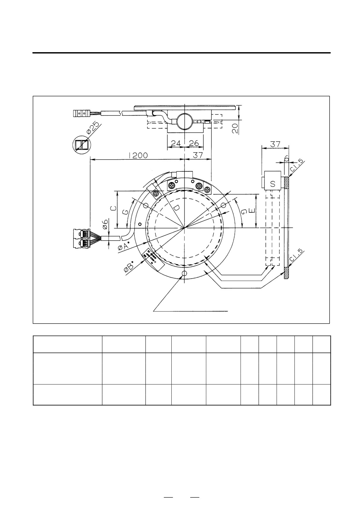
(a) BZ sensor (with mounting ring)
Detection ring B
Detection ring A
*Accessory (Honda)
Connector: Z-374
2 pcs
Sensor mounting ring
Contact: HKP-F413
12 pcs
3-φ 6.6 drill, equally spaced on φ F circumference
Mounting screw M6
10 or more
Number
Sensor drawing No.
Detection ring
φA*
φB*
C
D
E
φF
G
of teeth
A860-0392-T011
Ring 1
A860-0392-T014
Ring 4
256
108+0.020
140h6–0.0
25
51
R80
46
124
30°
A860-0392-T081
Ring 6
A860-0392-T012
Ring 2
0.019
128
56H6 -0.019
100h6–0.022
25
R57
20
78
10°
A860-0392-T082
Ring 7
For the outside dimensions of the detection rings, see Item (c).
565
12. DETECTORS FOR THE SPINDLE
B-65162E/03
NOTE
- Use the BZ sensor at temperatures not exceeding 80°C.
- The BZ sensor is a precision device. It must be handled with care. In particular, ensure that
no force is applied to the S section.
- The sensor is an electronic device. Provide dust and drip protection on the machine so that
the sensor is not exposed to chips, oil, water, or any other harmful substance.
- Those dimensions that are marked with an asterisk (*) are the dimensions of the sensor
mounting ring. Design a socket and spigot joint on the machine side to match the dimensions.
If a socket joint on the machine side is designed incorrectly, an incorrect signal may be output.
- The gap between the sensor and detection ring is adjusted beforehand. However, an output
signal may not satisfy the specified value due to a socket and spigot joint error. Check the
output signals when mounting a sensor. If an output signal does not satisfy a specified value,
adjust the gap. For information about the output signal level for gap adjustment, refer to Part
II of ”FANUC Built-in AC Spindle Motor α Series Descriptions (B-65202EN).”
- Make a shielded wire connection.
- To ensure ease of maintenance, install a sensor in a location where it can be replaced easily.
- The detection ring of a sensor can be exchanged with another sensor provided the sensors
have the same drawing number.
- A sensor and detection ring cannot be combined if the detection ring is designed for a drawing
number different from that of the sensor.
- A mating connector (accessory) is provided with the BZ sensor.
566
B-65162E/03
12. DETECTORS FOR THE SPINDLE
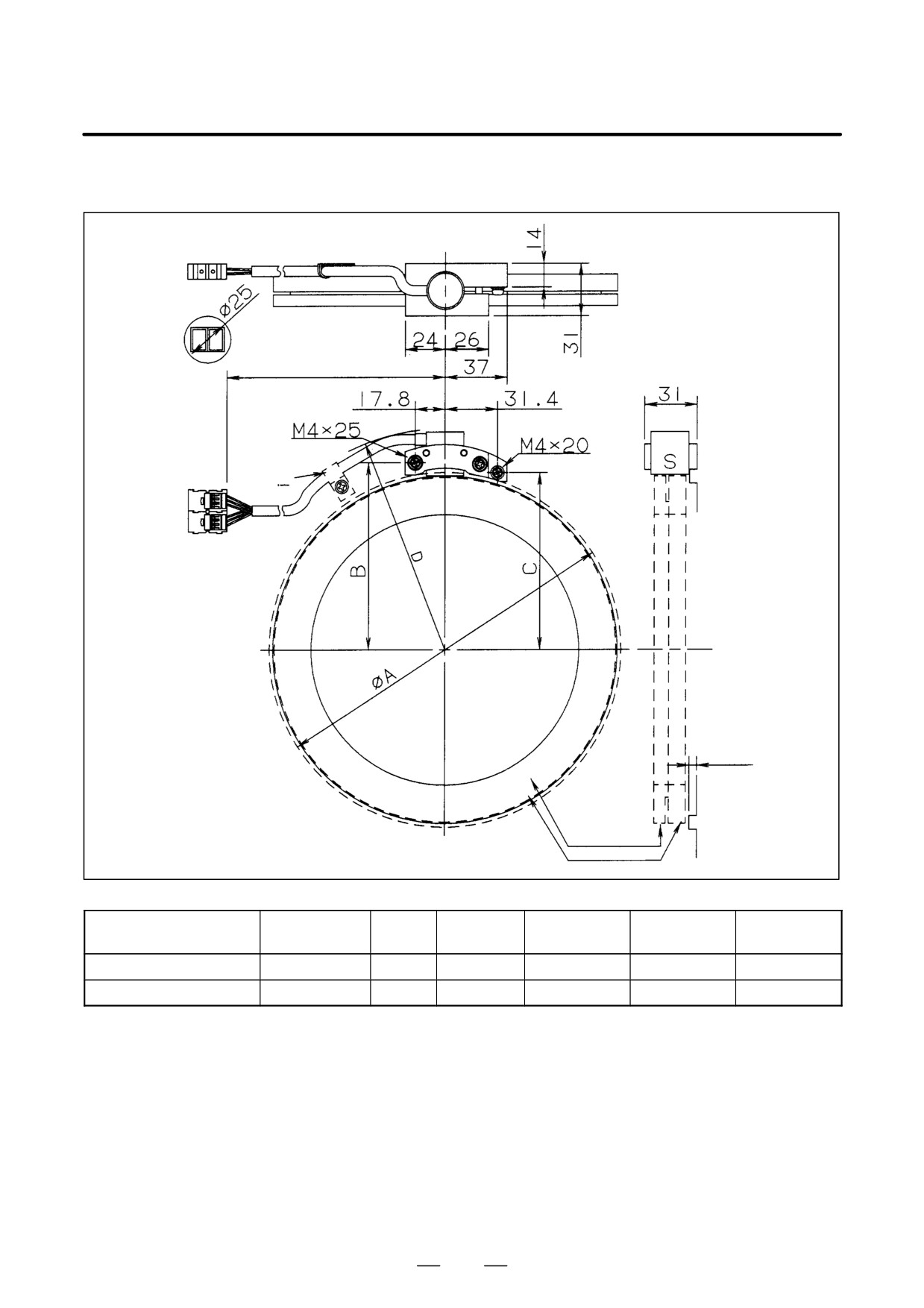
(b) BZ sensor (with no mounting ring)
Diameter of through hole
for connector
(φ15 for one each)
1200 (cable length)
(Note)
(Note)
(Note)
(socket and spigot joint on machine side)
(Note)
4.5 mm or
less
*Accessory (Honda)
Connector: Z-374
2 pcs
Detection ring B
Contact: HKP-F413
12 pcs
Detection ring A
Number
Sensor drawing No.
Detection ring
φA
B
C
D
of teeth
A860-0392-T013
Ring 3
512
210–0.030
110.8
104.8
R140
+0.0
A860-0392-T018
Ring 5
384
158
-0.025
84.3
78.3
R110
For the outside dimensions of the detection rings, see Item (c).
567
12. DETECTORS FOR THE SPINDLE
B-65162E/03
NOTE
-
Use the BZ sensor at temperatures not exceeding 80°C.
–
The BZ sensor is a precision device. It must be handled with care. In particular, ensure that
no force is applied to the S section.
-
The sensor is an electronic device. Provide dust and drip protection on the machine so that
the sensor is not exposed to chips, oil, water, or any other harmful substance.
-
When installing a BZ sensor, press it against the machine-side socket and spigot joint ( A in
size). (The machine-side socket and spigot joint is 4.5 mm high.) The gap between the sensor
and detection ring is adjusted beforehand. However, an output signal may not satisfy the
specified value due to a socket and spigot joint error. Check the output signals when mounting
a sensor. If an output signal does not satisfy the specified value, adjust the gap. For information
about the output signal level for gap adjustment, refer to Part II of ”FANUC Built-in AC Spindle
Motor α Series Descriptions (B-65202EN).”
-
To mount the BZ sensor, use screws of M4 x 20 mm and M4 x 25 mm.
–
Secure the cable at appropriate locations so that, when the cable is pulled, no force is directly
applied to the BZ sensor.
-
Make a shielded wire connection.
–
To ensure ease of maintenance, install a sensor in a location where the sensor can be replaced
easily.
-
The detection ring of a sensor can be exchanged with another sensor provided the sensors are
of the same drawing number.
-
A sensor cannot be combined with a detection ring if the detection ring is designed for a drawing
number different from that of the sensor.
-
A mating connector (accessory) is provided with the BZ sensor.
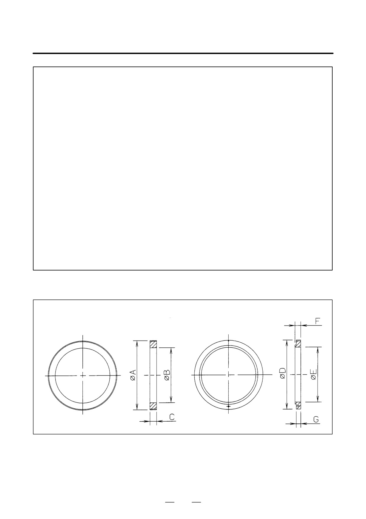
(c)
Detection ring
Detection ring A
Detection ring B
568
B-65162E/03
12. DETECTORS FOR THE SPINDLE
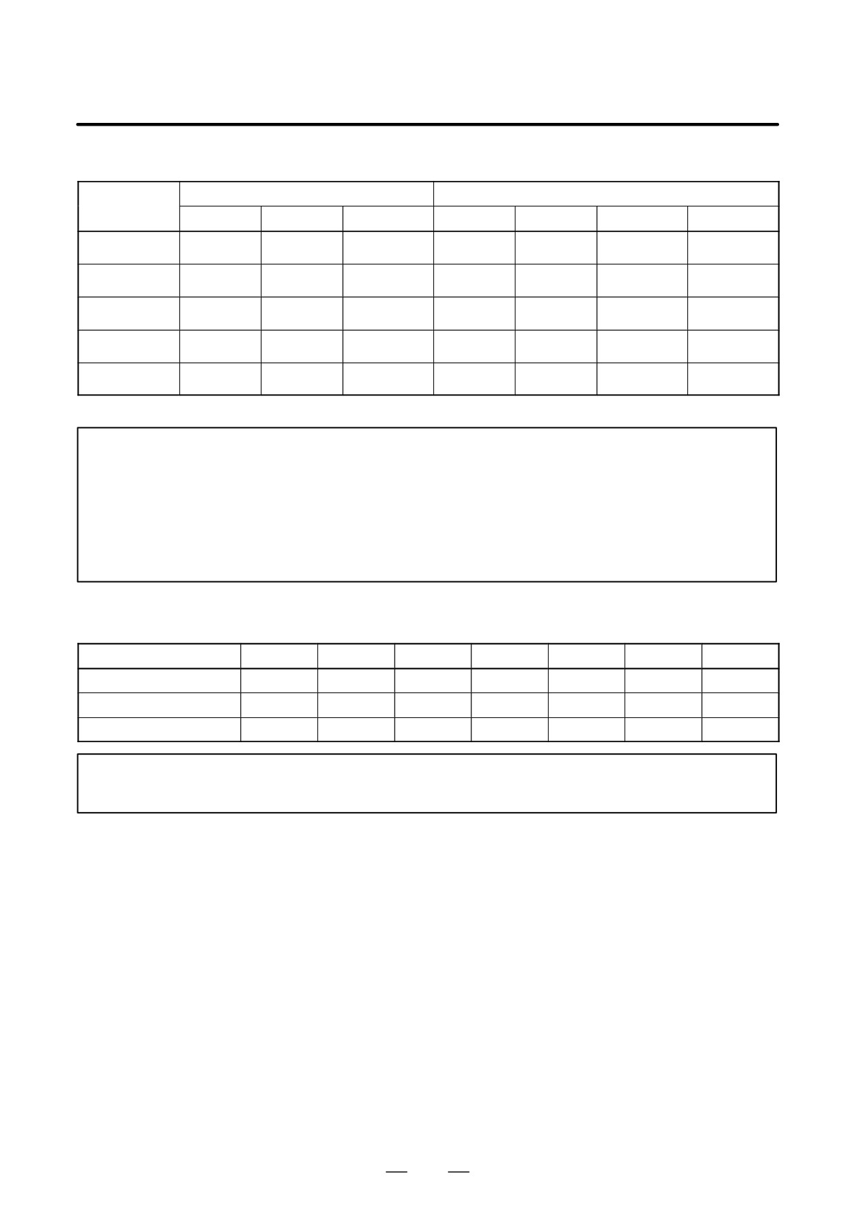
Detection ring dimensions
Detection ring A
Detection ring B
φA
φB
C
φD
φE
F
G
Ring 1, 6
103.2–0.020
82–0.018
10"0.1
103.2+0.0
82+0.0
8.6"0.1
6.7
-0.020
-0.018
Ring 2, 7
52–0.020
40–0.016
10"0.1
52+0.0
40+0.016
8.6"0.1
6.7
-0.020
-0.0
Ring 3
205.6–0.020
160–0.020
10"0.1
205.6+0.0
-0.020
160+0.020
-0.0
8.6"0.1
6.7
Ring 4
103.2–0.020
88–0.018
10"0.1
103.2+0.0
-0.020
88+0.0
-0.018
8.6"0.1
6.7
Ring 5
154.4–0.020
125+0.025
-0.0
10"0.1
154.4+0.0
-0.020
125–0.025
8.6"0.1
6.7
For the outside dimensions of the sensor, see Item (4) above.
NOTE
- Before mounting a ring on the spindle, press the ring into the sleeve.
- A ring can be reused only once.
- The outer tooth shape is special. So, ensure that the teeth are not deformed or chipped by an
external force.
- Check the output signal of the sensor. For output signal adjustment, refer to Part II of ”FANUC
Built-in AC Spindle Motor α Series Descriptions (B-65202EN).”
Maximum detection ring speed
Ring
Ring 1
Ring 2
Ring 3
Ring 4
Ring 5
Ring 6
Ring 7
Sensor drawing No.
T011
T012
T013
T014
T018
T081
T082
Number of teeth
256 teeth
128 teeth
512 teeth
256 teeth
384 teeth
256 teeth
128 teeth
Maximum speed (min-1)
15,000
20,000
10,000
15,000
15,000
30,000
50,000
NOTE
The allowance for shrink fitting depends on the maximum speed. For design, see Item (6).
569
12. DETECTORS FOR THE SPINDLE
B-65162E/03
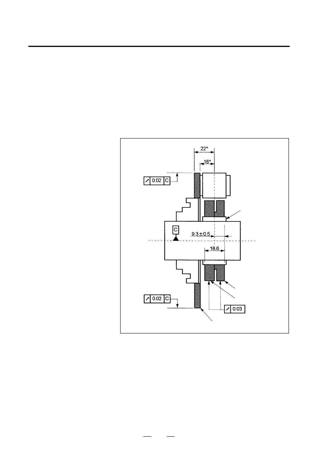
(5) Mounting the BZ Sensor
Mount ring A and ring B as shown below.
D Press-fit the rings into the sleeve, then press-fit the sleeve into the spindle.
Ensure that ring A and ring B fit snugly.
D Ensure that a half point (9.3 mm) of the thickness of ring A plus ring B is
aligned with the center of the sensor within an error of
0.5 mm.
D Ensure that the fluctuation of the rings with respect to the sensor is within
0.03 mm.
D The fluctuation of the mounting ring with respect to the center of the shaft
is within
0.02 mm.
Value 22 applies to other
than T013 and T018.
Value 16 applies to
T013 and T018.
Sensor
Sleeve
Shaft
Detection ring B
Detection ring A
Mounting ring
570
B-65162E/03
12. DETECTORS FOR THE SPINDLE
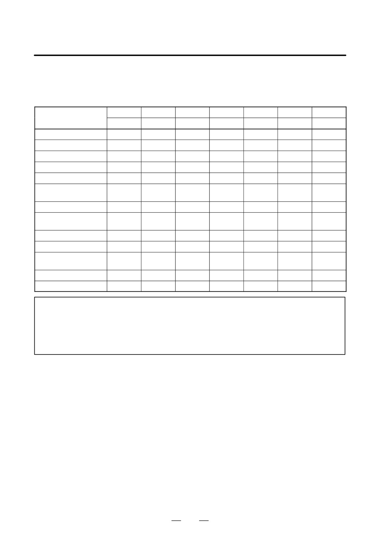
(6) Allowance for Shrink Fitting
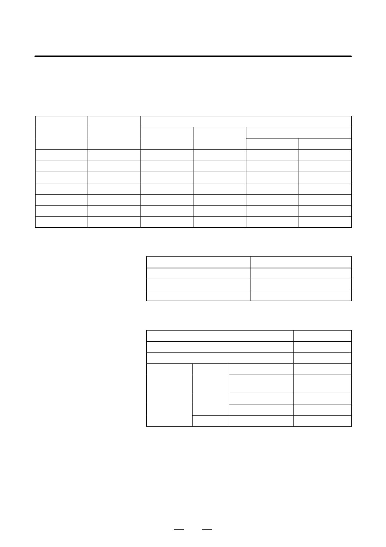
The table below indicates the allowances for detection ring shrink fitting
for each of the maximum speeds.
Unit: µm
T011
T012
T013
T014
T018
T081
T082
Maximum speed (min-1)
Ring 1
Ring 2
Ring 3
Ring 4
Ring 5
Ring 6
Ring 7
3000
φ7 to φ35
φ6 to φ32
φ11 to φ41
φ7 to φ35
φ8 to φ43
φ7 to φ35
φ6 to φ32
3500
↓
↓
φ13 to φ43
↓
φ9 to φ44
↓
↓
4500
↓
↓
φ19 to φ49
↓
φ11 to φ46
↓
↓
6000
φ9 to φ37
↓
φ29 to φ59
φ9 to φ37
φ15 to φ50
φ9 to φ37
↓
8000
φ11 to φ39
↓
φ47 to φ77
φ11 to φ39
φ24 to φ59
φ11 to φ39
↓
φ71 to
10000
φ14 to φ42
↓
φ15 to φ43
φ35 to φ70
φ14 to φ42
↓
φ101
12000
φ18 to φ46
φ7 to φ33
φ19 to φ47
φ47 to φ82
φ18 to φ46
φ7 to φ33
φ71 to
15000
φ26 to φ54
φ8 to φ34
φ28 to φ56
φ26 to φ54
φ8 to φ34
φ106
20000
φ10 to φ36
φ41 to φ69
φ10 to φ36
25000
φ62 to φ90
φ12 to φ38
φ87 to
30000
φ15 to φ41
φ115
40000
φ23 to φ49
50000
φ33 to φ59
NOTE
- From the table above, select the shrink fitting allowance that matches a maximum speed and
type of ring being used. If an incorrect allowance is employed, idle rotation or damage can
result.
- The rings cannot be used at a maximum speed that does not appear in the table above. For
the maximum allowable speed of each ring, see Item (C).
571
12. DETECTORS FOR THE SPINDLE
B-65162E/03
12.3
OTHER DETECTORS
12.3.1
High-resolution
Magnetic Pulse Coder
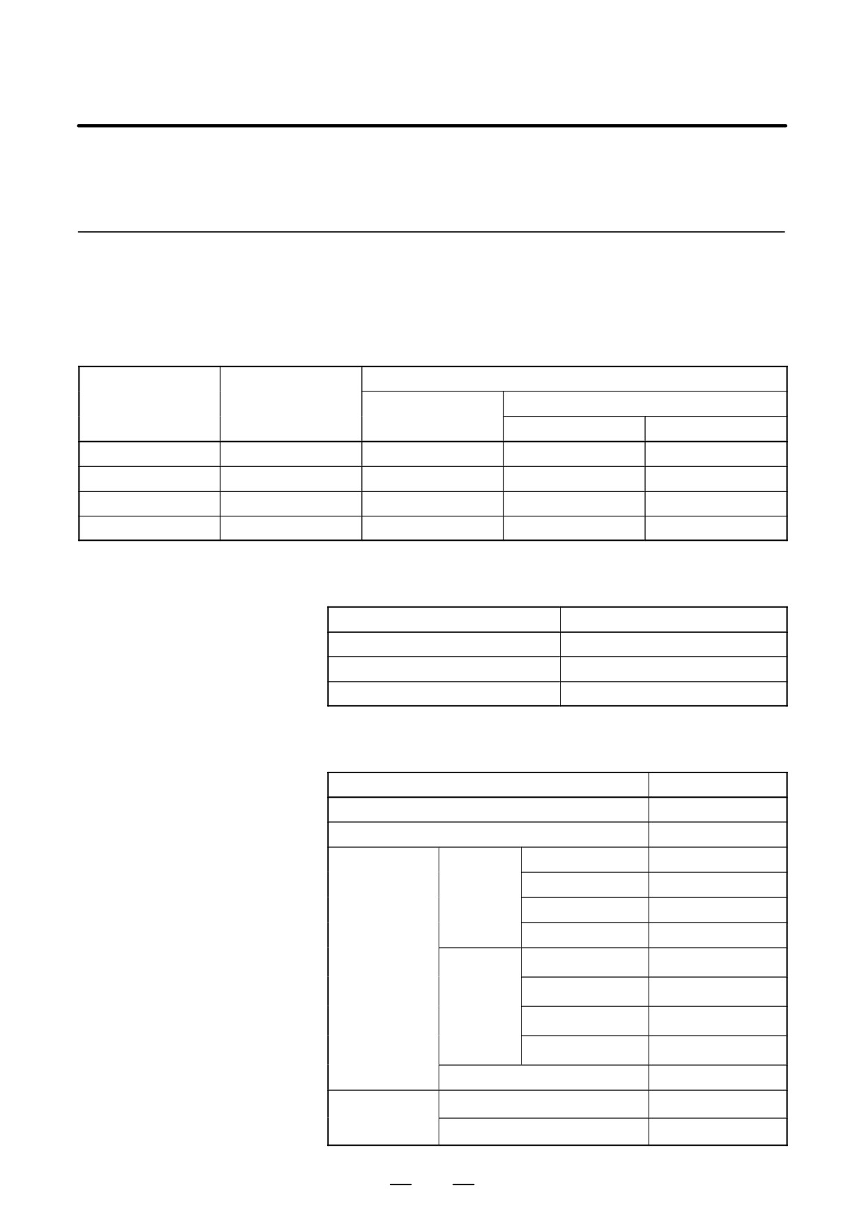
(1)
Names and Drawing Numbers
Table.12.3.1 (a) Names and Drawing Numbers
Remarks
Name
Drawing No.
Drum
Maximum speed
Inner diameter
Outer diameter
65 drums
A860-0382-T121
15,000min-1
φ50
φ65
97.5 drums
A860-0382-T122
13,000min-1
φ70
φ97.5
130 drums
A860-0382-T123
10,000min-1
φ105
φ130
195 drums
A860-0382-T124
6,500min-1
φ160
φ195
(2)
Absolute Maximum Ratings
Table.12.3.1 (b) Absolute Maximum Ratings
Item
Specifications
Power supply voltage
-0.5V to +7.0V
Operating temperature
0_C to +50_C
Humidity
95% RH or less
(3)
Electrical Specifications
Table.12.3.1 (c) Electrical Specifications
Item
Specifications
Power supply voltage
5V"5%
Current consumption
150mA or less
A860-0382-T121
1,000 /rev
Cs contour
control sig-
A860-0382-T122
1,500 /rev
nals
A1,RA1
A860-0382-T123
2,000 /rev
B1,RB1
A860-0382-T124
3,000 /rev
Signals
A860-0382-T121
128 pulses/rev
Output signals
equivalent
to position
A860-0382-T122
192 pulses/rev
coder sig-
nals
A860-0382-T123
256 pulses/rev
A3,RA3
B3,RB3
A860-0382-T124
384 pulses/rev
One-rotation signals Z,*Z
1 pulse/rev
Resolution (com-
Cs contour control signal
360,000 divisions/rev
bination with
SPM Type 2)
Position coder signal
4,096 divisions/rev
572