9/Series CNC Lathe. Operation and Programming Manual - page 26
Chapter 30
Using a 9/Series Dual--Processing System
Synchronization in MDI Mode
Synchronization M-codes can be programmed in MDI mode. These can
prove useful when attempting to manually start multiple programs from
some point other than the beginning or when it is necessary to execute
MDI programs on both processes simultaneously. By inserting a
synchronization M-code (by using MDI and pressing cycle start) you can
start a process executing, but place it in pause until you start the second
process and it executes the corresponding synchronization code.
Example 30.5
Synchronization in MDI Mode
Process 1 (MDI mode)
Comment
Process 2 (MDI mode)
Comment
N1 M100;
You can press <CYCLE START> and
this block will pause while you MDI the
necessary information into process 2.
N1 M100;
Pressing <CYCLE START> at this
block has the effect of starting both
processes’MDI program at the same
time.
G28 X10 Z10;
G28 X10 Z10;
Program Interrupts During Synchronization Blocks
Program interrupts can be performed while a process is being paused by a
synchronization M-code (see chapter 29 for details on interrupts). If the
process is paused when the interrupt is requested, the request will be
recognized; however, the interrupt will not execute until the
synchronization M-code is released by the other process, executing the
appropriate synchronization code.
<CYCLE STOP> During Synchronization Blocks
Press <CYCLE STOP> places in cycle suspend mode while it is paused by a
synchronization M-code. This lets you perform most manual operations
(such as jog retract) and other functions normally available to a process in
cycle suspend mode. No loss of synchronization occurs while the process
is in cycle suspend.
Block retrace will not retrace through part program blocks with
synchronization M-codes in them. The error message “NO FURTHER
RETRACE ALLOWED” appears.
30-11
Chapter 30
Using a 9/Series Dual--Processing System
For example, press <CYCLE STOP> to place process 1 in cycle suspend
mode, while process 1 is waiting for process 2 to execute an M101. Later,
when you request <CYCLE START> for process 1, the synchronization
M-code is re-activated and process 1 is again paused, waiting for process 2
to execute an M101. If, while process 1 is in cycle suspend mode, process
2 executed an M101, process 2 will pause at that synchronization block.
Pressing <CYCLE START> for process 1 releases the pause for both process,
and they will resume program execution.
30.4
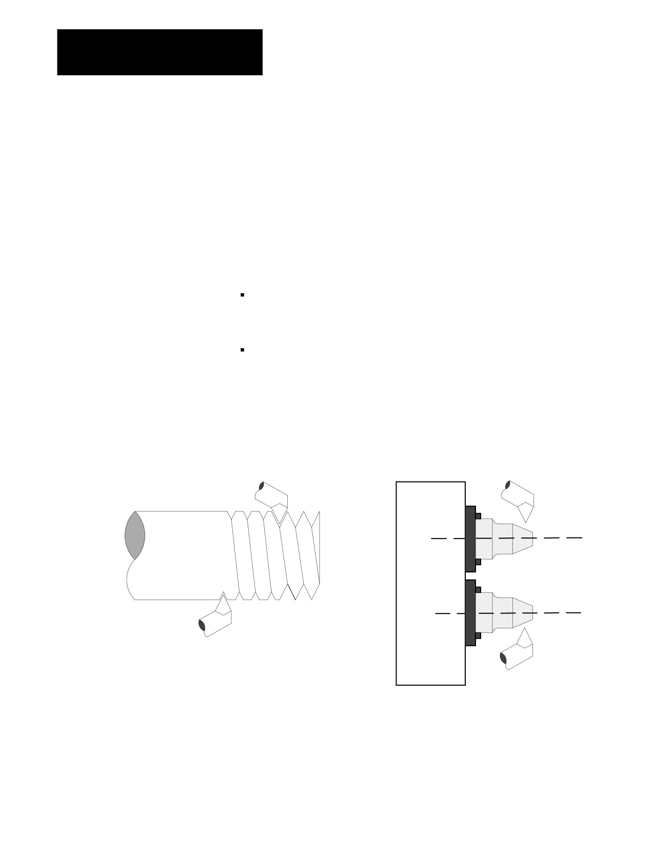
There are two basic configurations for the spindle with dual-processing
systems. These are:
Spindle Control for
Dual- Processing Systems
Shared Spindle Configuration -- The system contains one spindle that is
controlled by both processes (in addition to any other spindles the
system may contain).
Separate Spindle Configuration -- The system contains one or more
separate spindles for each process. In some cases these spindles are on
completely separate machines.
Figure 30.4
Example of Different Dual-Processing Spindle Configurations
Shared Spindle Configuration
Separate Spindle Configuration
Dual-Turret Lathe
Dual-Spindle Lathe
Process 2
Process 1
2nd Threading Pass
Process 1
1st Threading Pass
Process 2
12599-I
Both the shared and separate spindle configurations can have additional
spindles. These spindles must be assigned to only one process and cannot
be controlled by more than one process. When a process has more than
one spindle under its control, use a G12.x command to select the currently
active spindle. Refer to chapter 17 for details.
30-12
Chapter 30
Using a 9/Series Dual--Processing System
30.4.1
Shared spindle configurations are for those dual-processing systems that
have one spindle that must be controlled by both processes. See
Shared Spindle
Figure 30.4. As a general rule for this type of machine, spindle control is
Configurations
given to the process currently requesting spindle control.
WARNING: It is the programmer’s responsibility to watch for
conflicting overlap of spindle control between the two
processes. For example, one process should not request
clockwise spindle rotation while the other process requires
counterclockwise rotation. Prevention of overlapping spindle
control can be accomplished through synchronization M-codes.
See page 30-7.
Simple Spindle Speed and Direction
The process that requests a change in spindle speed or direction gets
control of the shared spindle. This can cause problems when both
processes are performing operations that require control over the spindle.
For example, consider the following program segments.
Process 1
Process 2
Shared Spindle Operation
N51 G97 S200 M04;
200 RPM, counterclockwise
N21 G97 S500 M03;
500 RPM, clockwise
N52 G01 X10 Z5;
500 RPM, clockwise
(cutting with process 2 direction
and RPM)
N22 G01 X12 Z--1
500 RPM, clockwise
N53 X12 Z3 S275;
275 RPM, counterclockwise
(cutting with process 1 direction
and RPM)
30-13

Chapter 30
Using a 9/Series Dual--Processing System
Use the synchronization M-codes to properly dictate which process has
control of the spindle at any given time. Adding a synchronization M-code
to the above program segments would remedy the problem of process 1
cutting at the wrong RPM and in the wrong direction. For example:
Process 1
Process 2
Shared Spindle Operation
N51 G97 S200 M04;
200 RPM, counterclockwise
N21 M101;
200 RPM, counterclockwise
(process 2 pauses, waiting for
M101 in process 1)
N52 G01 X10 Z5;
200 RPM, counterclockwise
N53 X12 Z3 S275;
275 RPM, counterclockwise
N53 M101;
275 RPM, counterclockwise
N22 G97 S500 M03;
500 RPM, clockwise
N22 G01 X12 Z--1;
500 RPM, clockwise
Multiple Spindle Systems
Your system installer has the option of assigning additional spindles (in
addition to the shared spindle) to the different processes. These spindles
cannot be shared. Your system can have only one shared spindle between
processes. Additional spindles must be assigned to specific processes in
AMP and can be controlled by only that process.
Controlling these additional spindles in the part program is accomplished
in the same way as single processing systems. The spindle being
controlled must first be selected by using a G12.1, G12.2, or G12.3. Refer
to page 17-9 for details on programming these spindle G codes. Your
system installer selects in AMP which spindle (spindle 1, spindle 2, or
spindle 3) is the shared spindle.
Exclusive Operations on a Shared Spindle.
There are several features that require exclusive use of the spindle. When
you execute these features, changes to the spindle cannot be performed by
another process until the feature is completed or canceled. These features
include:
M19 -- Spindle Orient
G96 -- Constant Surface Speed (CSS)
G16.1, G16.2 -- Virtual C, Cylindrical and End-Face Milling
Fixed cycles that require spindle control include:
- G84 (right hand tapping cycle)
- G84.1 (left hand tapping cycle)
- G86.1, G87, G88 (boring cycles)
30-14

Chapter 30
Using a 9/Series Dual--Processing System
An error is generated and the process enters cycle stop if you attempt to
activate one of these features while one is already active in another
process. For example, if process 1 is currently performing virtual C on the
shared spindle and process 2 attempts to execute a G84 right hand tapping
block, process 2 will generate an error and enter cycle stop. Process one
will continue until completion or until it encounters a synchronization
M-code. Any attempt to change the spindle speed or direction (via M03,
M04, or M05) will have the same results.
Threading on a Shared Spindle
Simple threading (G33 or G34) and the threading cycles (G21 and G78)
can be performed on a shared spindle. Make sure that the spindle speed or
direction is not changed by process 2 (see page 30-13).
Process 1
Process 2
Spindle Operation
N15 G33 X10 Z10 F20 S100;
Synchronizes Z axis motion
with spindle for threading.
N17 M03 S200;
Will not cancel threading
synchronization on process 1;
however, it will change
threading speed or direction or
both.
Both processes can also perform threading from the same spindle.
Synchronization of the spindle will be performed from the same marker
point. Both processes can cut the same thread if the same thread lead is
programmed in both processes.
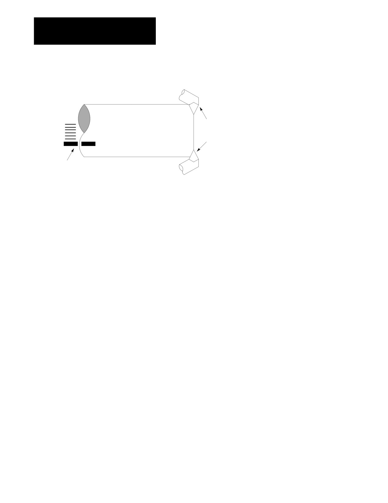
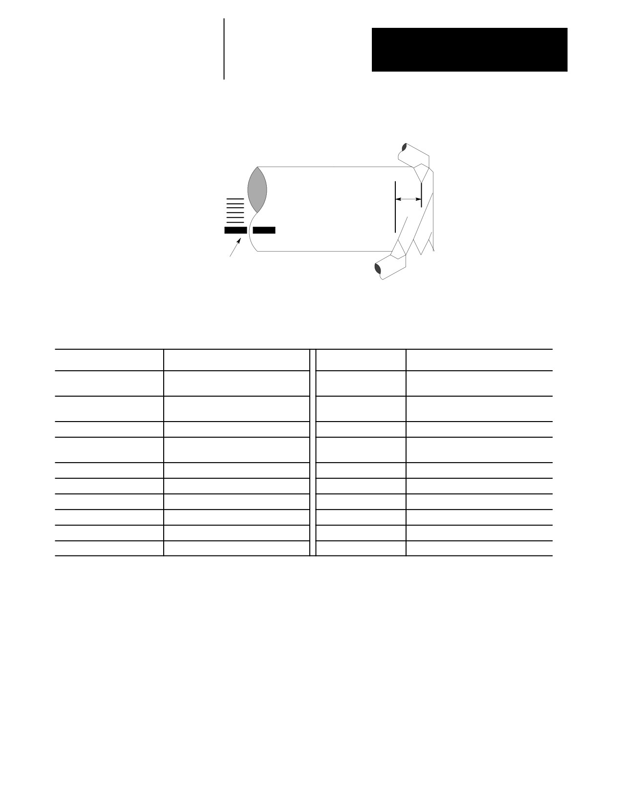
Important: When you use two processes to cut the same thread, the
position of the cutting tool has a significant impact on the thread being cut.
Both processes key off of the same spindle marker, so it is necessary to
alter the start point of one of the processes. Failure to do so results in a
multistart thread.
30-15
Chapter 30
Using a 9/Series Dual--Processing System
Figure 30.5
Multi-Start Thread When Same Start Point Is Used
Process 2
2nd Threading Pass
If both processes key off same
marker pulse, then multi-start thread
results.
Marker
Process 1
12600-I
1st Threading Pass
Use this formula to calculate the amount the start points must be offset:
Shift = q / 360 * F
Where:
Shift - is the amount the start point of the threads should be offset
q- the angular distance around the spindle between the two processes
(always measured in the direction of spindle rotation)
F - the length of the thread lead
For example, assuming your cutting tools are on directly opposite sides of
the spindle, q would be 180 degrees. If the thread lead were 20 threads per
inch, F would be 1 / 20. The shift would then equal:
Shift = 180 / 360 * 1/20 = .025 inch.
In cases where the second process is not exactly 180 degrees opposite the
other process, consider the above equation for the direction of spindle
rotation. This consideration is made by always measuring q in the
direction of spindle rotation.
30-16
Chapter 30
Using a 9/Series Dual--Processing System
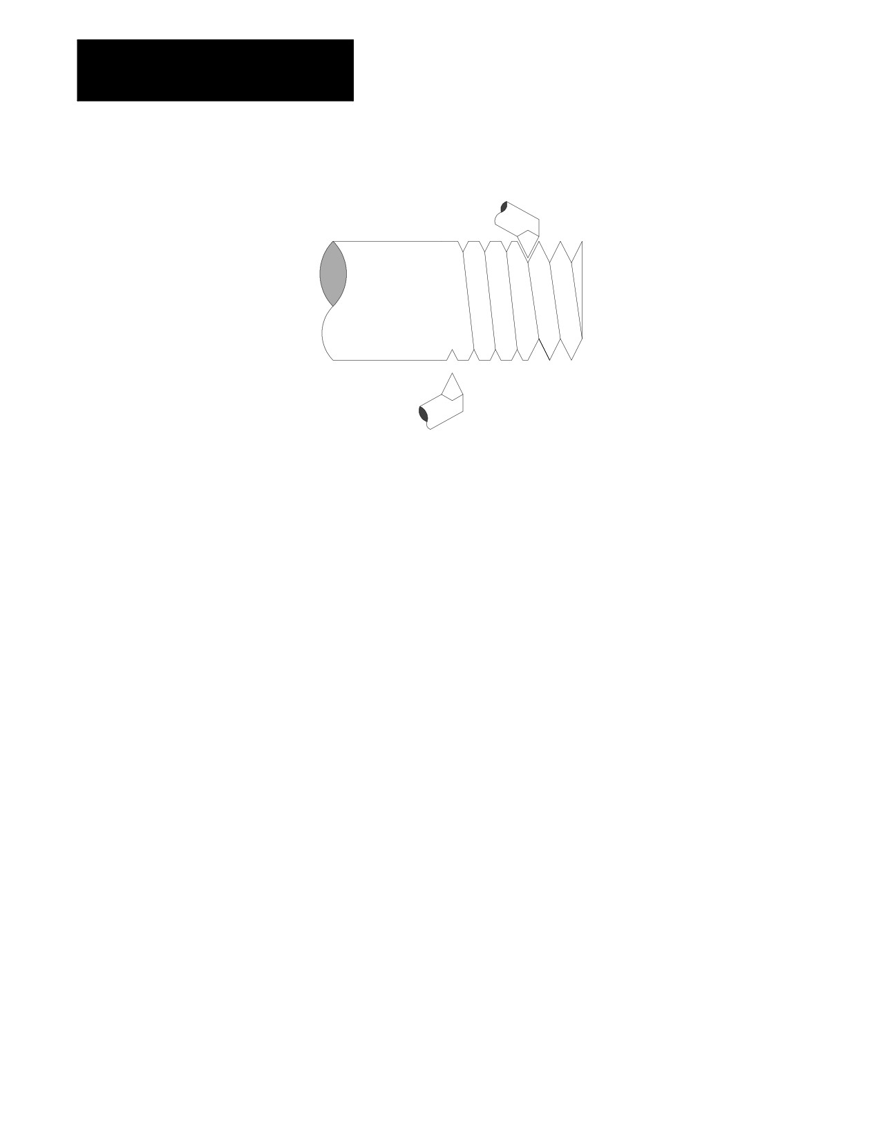
Figure 30.6
Identical Thread Is Cut When Start Point Is Shifted Using Equation
Process 2
2nd Threading Pass
.025
Marker
Process 1
1st Threading Pass
12601-I
Example 30.6
Threading on Both Processes with a Shared Spindle
Process 1
Comment
Process 2
Comment
N1 G00 X10. Z10 S500. M03;
Move to process 1 start point and start
spindle rotation
N1 G00 X10. Z11.;
Z start point is shifted one inch from
process 2
N3 G21 X4.8 Z5. E2.;
Start threading on process 1
N2 M100;
Synchronize to make sure process two
cuts thread behind process 1
N2 M100;
Allow process 2 to start threading
N3 G21 X4.65 Z5. E2.;
Start threading on process 2
N4 X4.5;G04P5;
N4 X4.4;
N5 X4.35;
N5 4.3;
30-17
Chapter 30
Using a 9/Series Dual--Processing System
Figure 30.7
Cutting a Thread Using Both Processes
Process 2
2nd Threading Pass
Process 1
1st Threading Pass
12602-I
Spindle Orient on a Shared Spindle
Both processes can request a spindle orient. If one process requests a
spindle orient while the other process’s spindle orient command has not
completed, the control generates an error. The process that requested the
second spindle orient is forced into cycle stop mode.
30.4.2
This system configuration contains a separate spindle for each process. In
Separate Spindle
some cases the spindles are on completely separate machines. At no time
are spindle commands shared by both processes.
Configuration
This type of system operates identically to a single-process system. Each
process has full and total control of its assigned spindles. Each process can
be assigned multiple spindles, but each spindle is specifically assigned to
that process. No other process can control a spindle assigned to a specific
process. The spindle currently being controlled by a process is selected
with a G12.x command. See chapter 17 for details.
Important: Do not assume that because your system has more than one
spindle that you have this separate spindle configuration. It is possible that
one of your spindles is shared by both processes, and the additional
spindle(s) is assigned to a specific process(es). Refer to your system
installer’s documentation to determine what type of spindle configuration
your system contains.
30-18
Chapter 30
Using a 9/Series Dual--Processing System
30.5
The Interference Checking feature is designed to help prevent collisions by
the axes of a dual-processing machine.
Using Interference Checking
with a Dual-Process Lathe
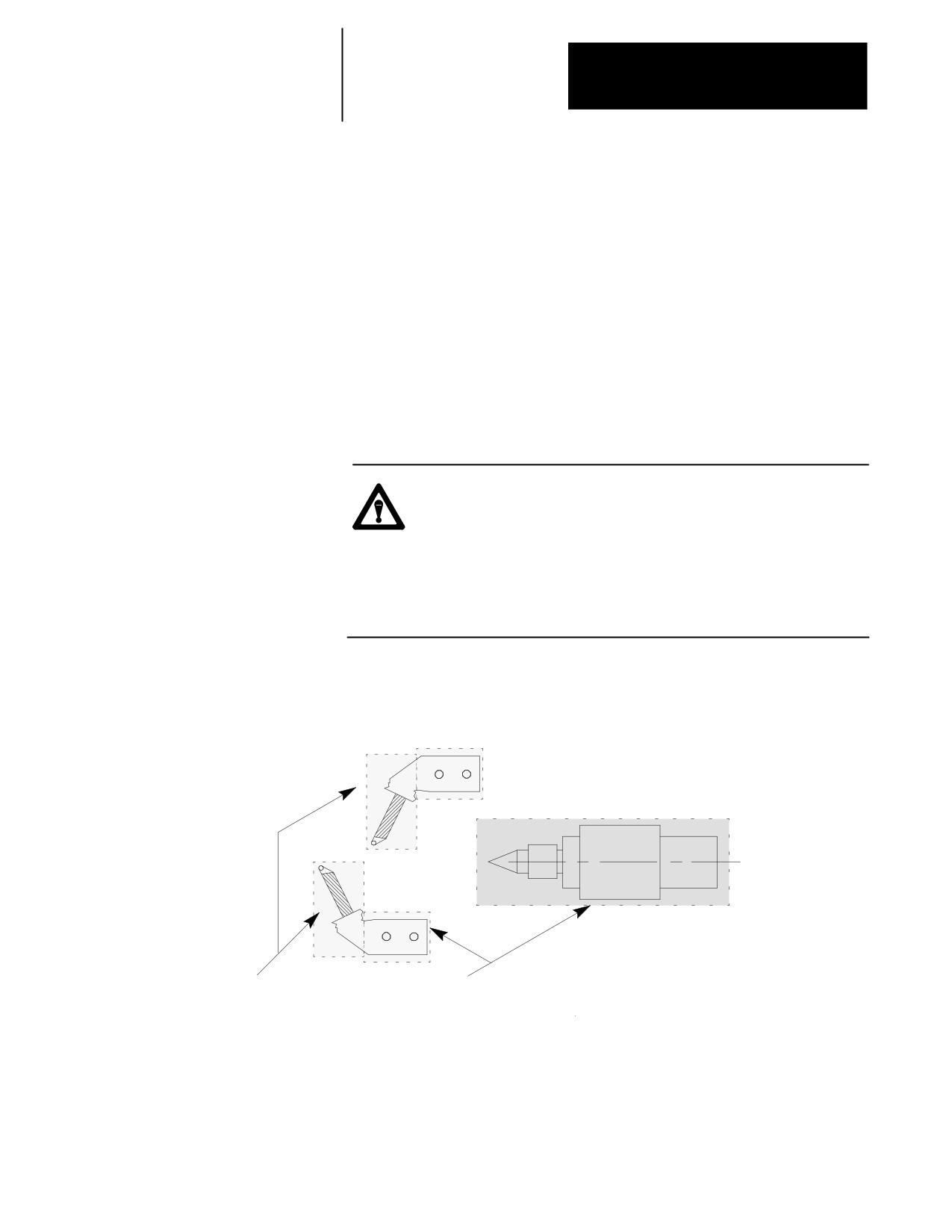
Interference checking provides an area (usually around the cutting tool or
tool turret for each process) that defines a boundary that moves with the
tool. The other process cannot enter into this boundary. This helps prevent
collisions.
For interference checking to function properly, you must define and
activate this boundary for both processes. When one process’s boundary
attempts to enter another process’s boundary, one process enters cycle
suspend, preventing it from entering the protected area. In the case of an
unavoidable direct collision, both processes stop. An error message is
displayed for both processes. The two boundaries cannot intersect.
CAUTION: These interference boundaries only help prevent
collision with another interference boundary configured for
another process. They do not protect against collisions with
other machine fixtures that may or may not be protected by a
programmable zone or software overtravel. They do not
account for any tool offsets that are active at the time. They are
absolute positions.
Figure 30.8
Interference Check Helps Prevent Tool Fixtures from Colliding
Programmable
Zone 1
Tailstock
Interference checking does not protect programmable zones.
Area protected against
Only tool tip location is monitored for a programmable zone. Possible
collision by interference
collision between these areas.
checking. No collision
12603-I
between these areas.
30-19
Chapter 30
Using a 9/Series Dual--Processing System
Activating Interference Checking
The interference boundaries for each process are entered into the
interference checking tables. These tables relate the boundaries to specific
tool or offset geometries. The system installer selects the number of
boundaries that are available (from 1-32) for each process.
Each process can have a different interference boundary number active at
the same time. Activating an interference boundary for only one process is
not sufficient to activate interference checking. Each process must have an
active, valid interference boundary.
The system installer determines how the different interference boundaries
are activated for each process through PAL. Refer to your system
installer’s documentation for details on activating these boundaries.
Before interference checking can be activated, all axes that make up a
boundary must be homed.
Important: Your system installer has the option to determine with PAL
when interference checking will become active. Interference checking is
available in:
manual mode
automatic and MDI modes
manual, automatic, and MDI modes
Refer to your system installer’s documentation for details.
Once interference checking is turned on, it remains active in that mode
(Auto, MDI, or Manual) until turned off through the system installer’s
PAL. This includes when no program is active, a control reset is
performed, or even when the control is in E-Stop (unless PAL has been
specifically written to do so). Interference checking can also be active in
mechanical handle feed mode (servo off).
Interference checking is not performed on the part program during
QuickCheck mode. Interference checking is still active in QuickCheck;
however, since axis motion is not usually present during QuickCheck,
programmed collisions are not detected.
Important: Shared axes can only be defined in an interference zone in one
process. If the system installer defines the same shared axis to be in an
interference zone for both processes the control generates an error.
30-20
Chapter 30
Using a 9/Series Dual--Processing System
Using Interference Checking to Prevent Collisions
When two protected areas are about to collide, the control suspends
motion, stopping one or both of the processes and preventing a collision.
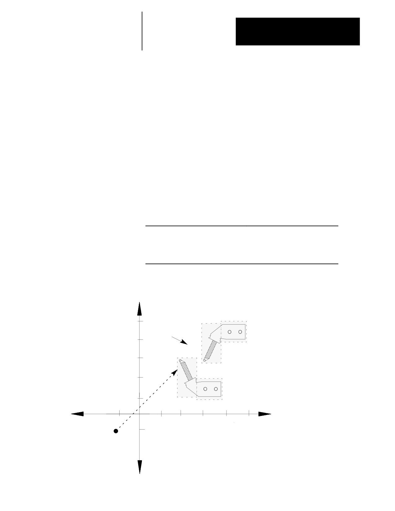
In Example 30.7, process 1 will collide with process 2. Since process 2 is
stationary, the control puts process 1 in cycle suspend to prevent a
collision. Once the control detects the collision, it suspends the action.
Interference checking operates in real time. It is not checked in block
lookahead. The control detects a collision immediately before the
boundaries overlap and suspends one or both of the processes, halting the
axes with an abrupt, undecelerated stop.
Example 30.7
Collision Programmed with Interference Checking On
Process 1
Process 2
N1 G90 G70;
N1 G90 G70;
N2 G00 Z-2.1 X-2.1;
N2 G00 Z6 X6;
N3 G00 Z8 X9;
N3 M30;
N4 M30;
Figure 30.9
Results of Example 30.7
X
Process 2
Collision avoided
10
immediately before
boundaries overlap
8
6
4
Process 1
2
Z
-2
2
4
6
8
10
--2
12604-I
30-21
Chapter 30
Using a 9/Series Dual--Processing System
30.5.1
The control can store as many as 32 different boundaries for each process.
Two separate areas make up each of these boundaries. Both axes are
Measuring Interference
activated when the boundary is activated through PAL. Figure 30.10
Boundaries
illustrates the use of two areas to make up interference boundary 01.
Figure 30.10
Using Two Areas to Define an Interference Checking Boundary
Area 2
These areas define an interference boundary.
A maximum of 32 boundaries can be defined
containing 64 actual areas (two areas in each
boundary).
Area 1
12605-I
At least one area must be defined for a boundary to be considered valid for
activation. If only one area is defined, the control assumes the second area
does not exist.
Areas for interference checking are defined in the machine coordinate
system for the fixtures positions as the axis sits at the home position.
Only two axes can be entered into the interference tables to define a
boundary. Your system installer selects these two axes in AMP. Follow
this procedure to measure values defining your interference areas:
1.
Return the axes to the home position (with no offsets active). This
can be accomplished by manually homing the machine (see chapter
4) or by programing a G28 (see chapter 14).
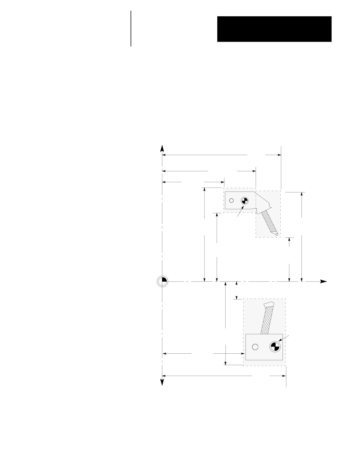
2.
Measure the values defining the interference area for each axis as
shown in Figure 30.11.
You will probably need to take different measurements for all of the
different fixtures and tools you will be using. Regardless of the tool
or fixture being used, the machine must remain at machine home
(with no offsets active) when the measurements are taken.
Interference areas are always measured as radius values. Data cannot
be entered into the interference tables as diameter values.
30-22
Chapter 30
Using a 9/Series Dual--Processing System
Important: Your system installer determines the relationship of the
machine coordinate systems between processes (relative location of zero
points and direction of positive travel) in AMP and through hardware.
This manual assumes the machine coordinate systems of both processes are
as shown in Figure 30.11. Refer to your system installer’s documentation
for details on how your machine coordinate systems are configured.
Figure 30.11
Measuring Interference Checking Areas
Z Plus
+X
Area 2
Process 1
Z Plus
Area 1
Z Minus
Area 2
Z Minus
Area 1
Area 1
Area 2
Machine
X Plus
X Plus
Home
Area 1
Area 2
Process 1
X Minus
Area 1
X Minus
Area 2
Machine
Coordinate
X Minus
Area 1
Z
System Zero Point
Area 1
(Both Processes)
X Plus
Area 1
Machine Home
Z Minus
Process 2
Area 1
Z Plus
Area 1
+X
Process 2
12606-I
30-23
Chapter 30
Using a 9/Series Dual--Processing System
Important: These areas are measured from the machine coordinate zero
point to the extremes of the fixture encompassed by the zone when the
machine is at home. The machine coordinate system zero point and
machine home are frequently not the same point on the machine. Machine
home is a fixed mechanical position established by the homing sequence
off hardware homing switches. The machine coordinate system zero point
is established in AMP and referenced from the machine home point (see
chapter 11 for details). Refer to your system installer’s documentation for
information regarding the location of machine coordinate system zero. For
interference checking to function properly, both processes must have the
same zero point, but they can have different home locations.
CAUTION: The distance between the boundaries before a
collision is detected is dependant upon factors such as:
speed of the axes
direction of axis travel with relationship to one another
For example, a programmed collision between two axes
traveling at rapid directly towards one another may not be
detected in time to fully stop the axes before some overlap of
the interference boundary occurs. We recommend making your
boundary areas as large as possible (definitely larger than the
actual physical dimensions of the protected fixture) to allow for
this potential overlap condition.
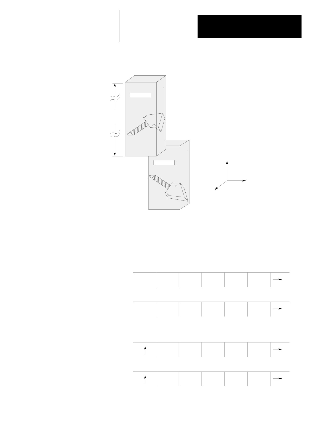
Only two axes can be entered in an interference table (available axes are
configured in AMP). To prevent a collision, other axes must rely on
protection by this interference area, or depend on you to use extra care
when programming or manually positioning the axes to prevent a collision.
30-24
Chapter 30
Using a 9/Series Dual--Processing System
Figure 30.12
Protecting Additional Axes with Interference Checking
Though only X and Z define this interference area,
some protection is also offered to W since an X or Z collision
Process 1
would be detected anytime W would collide. This protection,
however, will cause the control to detect a collision even if
sufficient clearance exists on the W axis. Disable interference
No limits
checking when it is necessary to overlap a third axis.
for the W
axis
W
Process 2
Z
X
12607-I
30.5.2
To manually enter values into the interference checking tables, follow this
procedure:
Entering Interference Values
Manually
1.
Press the {SYSTEM SUPORT} softkey.
(softkey level 1)
PRGRAM
FRONT
MACRO
PRGRAM
SYSTEM
MANAGE
PANEL
PARAM
CHECK
SUPORT
OFFSET
ERROR
PASS-
SWITCH
MESAGE
WORD
LANG
2.
Press the {PROGRAM PARAM} softkey.
(softkey level 2)
PRGRAM
AMP
DEVICE
MONI-
TIME
PARAM
SETUP
TOR
PARTS
PTOM
SI/OEM
30-25
Chapter 30
Using a 9/Series Dual--Processing System
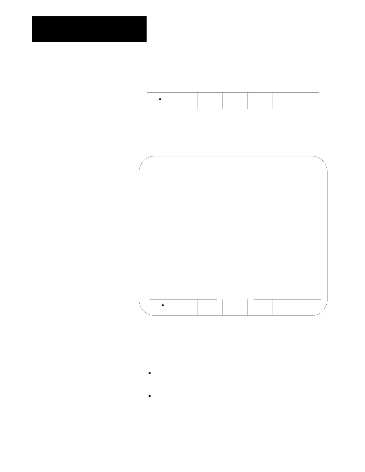
3.
Press the {INTERF CHECK} softkey to display the interference
checking data entry screen shown in Figure 30.13.
(softkey level 3)
ZONE
F1-F9
DRLCYC
INTERF
LIMITS
PARAM
CHECK
Figure 30.13
Interference Checking Data Table
INTERFERENCE TABLE
PAGE
1
OF 32
TOOL NO
AREA 1
AREA 2
*1
[INCH]
[INCH]
X PLUS
1.5000
1.5000
X MINUS
-.5000
-1.0000
Z PLUS
1.5000
6.0000
Z MINUS
0.0000
1.5000
<FRONT TURRET>
SEARCH
REPLCE
ADD TO
MORE
BACKUP
NUMBER
VALUE
VALUE
ZONES
INTERF
4.
Select a process. Refer to the system installer’s documentation for
details on selecting a process, or press the [PROC SELECT] key.
5.
Select a boundary number to enter by using one of these two
methods. Press:
the {MORE ZONES} softkey, or press the [Ø] key while holding
down the [SHIFT] key.
the {SEARCH NUMBER} softkey. Enter the desired boundary number
to search for and press the [TRANSMIT] key.
30-26
Chapter 30
Using a 9/Series Dual--Processing System
This boundary number should be the same as the tool geometry
number (T-word) that will be active when the tool and/or fixture is
being controlled. Refer to your system installer’s documentation for
details on which tool or fixture corresponds to which interference
boundary number (1-32).
6.
Use the up or down cursor keys to move the block cursor to the
interference area parameter to be changed. The selected field appears
in reverse video.
7.
If necessary, change the measurement units by using MDI. Units
currently used in the table are determined by the current mode of the
process (G70 inch or G71 metric).
8.
Enter the boundary area values as determined on page 30-22. Enter
values in one of two ways:
Press This
Then:
Press:
The New Value:
Softkey:
{REPLCE
Type in the new value.
[TRANSMIT]
replaces the old value
VALUE}
for that feedrate.
{ADD TO
Type in the new value.
[TRANSMIT]
is added to the old
VALUE}
value for that area.
9.
Repeat this procedure for each process until all boundaries are
entered.
30.5.3
You can enter data in the interference tables by programming the correct
G10 command. This section describes the use of the G10 commands.
Entering Interference Values
through Programming
Important: The active boundary and the value in the interference
(G10L5 and G10L6)
boundary table change when a G10 code modifies the table value. Both
changes activate immediately.
When the process is in incremental mode (G91), any values entered in the
table with the G10 command are added to the currently existing offset
values. When the process is in absolute mode (G90), any values entered in
an offset table with the G10 command replace the currently existing offset
values.
Values can be entered into the table as inch or metric values. Select the
values you intend to enter by first programming the G-code that establishes
the mode you wish to use (G70 or G71).
30-27

Chapter 30
Using a 9/Series Dual--Processing System
This is a representation of the basic format for modifying the tables.
5
G10 L{
} P__ X___ Z___ I___ K___;
6
Where :
Is :
L(5-6)
The definition of which area in the table is being modified.
L5 - Modifies the Area 1 values
L6 - Modifies the Area 2 values
P
The boundary number of the interference boundary that is having its values changed is
specified following the P address.
X
The value to add to (in G91 mode) or replace (in G90 mode) the positive X axis value. This
value is always a radius value.
Z
The value to add to (in G91 mode) or replace (in G90 mode) the positive Z axis value.
I
The value to add to (in G91 mode) or replace (in G90 mode) the negative X axis value. This
value is always a radius value. I is the integrand word of the X axis.
K
The value to add to (in G91 mode) or replace (in G90 mode) the negative Z axis value. K is the
integrand word of the Z axis.
Programming this G10 code can change only the table values for the
process that has the G10 part program currently active. You must run
separate G10 programs in each process to set up each area.
Important: G10 blocks cannot be programmed when TTRC is active.
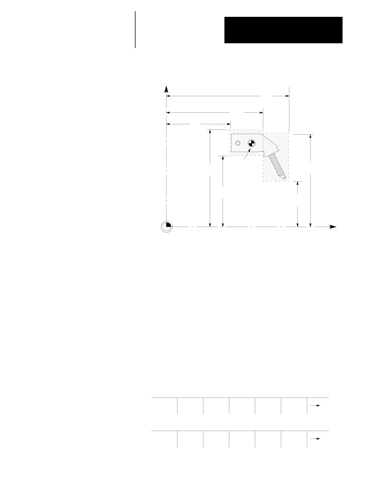
Example 30.8
Using G10 to Change the Interference Boundaries
N1 G90
G70;
N2 G10
L5 P1 Z19.5 K13 X19 I15;
Boundary number 1 area 1 is defined.
N3 G10
L6 P1 Z23 K19.5 X18.5 I11; Boundary number 1 area 2 is defined.
30-28
Chapter 30
Using a 9/Series Dual--Processing System
Example 30.9
Resulting Boundary from Example 30.8
+X
23”
Process 1
19.5”
13”
Area 1
Area 2
Machine
18.5”
19”
Home
Process 1
15”
Machine
11”
Coordinate
System Zero Point
(Both Processes)
+Z
12608-I
30.5.4
The control can save all of the information that is entered in the
interference tables as a backup. This is done by the control generating a
Backing Up Interference
program consisting of G10 blocks. These G10 blocks contain the
Tables
boundary numbers and their respective interference boundary values. Any
time you run this program, the set of values contained in these G10 blocks
replaces the current values in the interference tables. See page 30-27 for
details on the format of this G10 program.
The interference table program can be saved in control memory as a
program, or it can be sent to a peripheral device. The interference tables
can be easily setup again by executing this program in the appropriate
process.
To back up the interference tables, follow these directions:
1.
Press the {SYSTEM SUPORT} softkey.
(softkey level 1)
PRGRAM
FRONT
MACRO
PRGRAM
SYSTEM
MANAGE
PANEL
PARAM
CHECK
SUPORT
OFFSET
ERROR
PASS-
SWITCH
MESAGE
WORD
LANG
30-29

Chapter 30
Using a 9/Series Dual--Processing System
2.
Press the {PRGRAM PARAM} softkey.
(softkey level 2)
PRGRAM
AMP
DEVICE
MONI-
TIME
PARAM
SETUP
TOR
PARTS
PTOM
SI/OEM
3.
Press the {INTERF CHECK} softkey to display the interference
checking data entry screen as shown in Figure 30.13.
(softkey level 3)
ZONE
F1-F9
DRLCYC
PRBCYC
INTERF
LIMITS
PARAM
PARAM
CHECK
4.
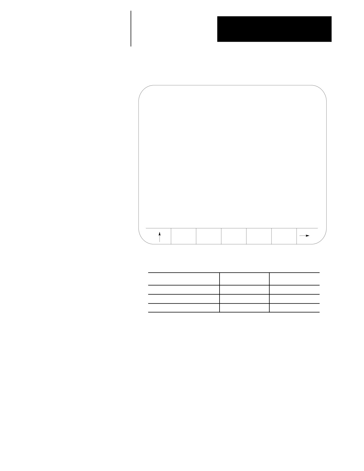
Press the {BACKUP INTERF} softkey. Figure 30.14 shows the backup
interference boundary screen.
(softkey level 4)
SEARCH
REPLCE
ADD TO
MORE
BACKUP
NUMBER
VALUE
VALUE
ZONES
INTERF
30-30
Chapter 30
Using a 9/Series Dual--Processing System
Figure 30.14
Backup Interference Boundary Screen
STORE TO BACKUP
INTERFERENCE TABLE
TO
TO
TO
PORT A
PORT B
FILE
5.
Determine the destination for the G10 program:
To Send the G10 Program To:
Press This Softkey:
Go to Step:
peripheral attached to port A
{TO PORT A}
7.
a peripheral attached to port B
{TO PORT B}
7.
to control memory
{TO FILE}
6.
6.
Press the {TO FILE} softkey. The control asks for a program name.
By using the alphanumeric keys on the operator panel, enter the
program name you wish to call the backup program . Press the
[TRANSMIT] key once you have entered the program name. See
chapter 10 on program names. The G10 program is saved under the
file name just entered.
7.
Press the {TO PORT A} or {TO PORT B} softkey. A {YES} or {NO}
softkey is displayed. Press {YES} to confirm or {NO} to abort. If you
confirm the operation, the G10 program is written to a peripheral
attached tot he selected port.
30-31
Chapter 30
Using a 9/Series Dual--Processing System
30.6
Your system installer can configure an axis to be shared by different
Shared Axes on
processes. With this feature multiple processes can execute part program
commands or perform manual operations on the same shared axis.
Dual- Processing Systems
A shared axis can not be commanded by more than one process
simultaneously. Control of the shared axis must be changed from process
to process thru the system installer’s PAL program.
30.6.1
Shared axes are shown on the position display in the order your system
Operating a Shared Axis
installer defines them in AMP. Shared axes are displayed only for the
process that currently has control of the shared axis (except on graphics
and axis monitor screens). When control of the shared axis is changed to a
different process, the axis is removed from the position display and added
to the new controlling process.
You can select to plot a shared axis for display on one of the graphics
screens regardless of the process currently controlling the shared axis. The
machine info window on graphics screen always shows only the axes
currently assigned to that process.
Homing a Shared Axis
A shared axis is homed like any other axis. It must be homed before it can
be positioned by a part program block. Home the shared axis in the
process that it is currently assigned. There is only one home position for a
shared axis (this position is independent of the current process). Once a
shared axis is homed in one process it becomes homed in any additional
processes as well. You do not need to home the shared axis in each
process.
Programmable Zones
Each process contains two independent programmable zones. Zones are
checked on a per process basis. The system installer can setup shared axis
zone values in AMP. A shared axis has the same zone values in both
processes. Shared axis zone values can be manually entered in either
process through the zone configuration table (see chapter 3 for details).
Zone 3 values can be changed in the part program as discussed in chapter
12. Each process can have a separate programmed value for for a shared
axis in zone 3 however these programmed values are only temporary and
do not overwrite the original AMP or manually entered table values.
Shared axis values in a programmable zone are monitored only in the
process currently controlling the shared axis. Shared axes are no longer
part of a programmable zone once they leave the process. Zones defined
to contain shared axes can be enabled and disabled in any process
regardless of the process currently controlling the shared axis. If a zone is
activated without a shared axis member, the shared axis zone values are
ignored for that process until the shared axis is switched into that process.
30-32
Chapter 30
Using a 9/Series Dual--Processing System
Block Retrace
Any part program blocks prior to an axis process switch can not be
retraced. If you attempt to retrace beyond the point that an axis switch
occurred, the control generates an error. Also an axis process switch can
not be performed if you are currently performing a block retrace.
Scaling
Scaling is performed on a per process basis. If you switch processes for a
scaled axis, scaling is removed in the new process. Scaling is then
reapplied to the axis when it returns to the process in which scaling is
active for that axis. You can scale the shared axis by different amounts in
different processes.
Axis Inhibit, Axis Detach, and Servo Off
When you turn any of these three features on for a shared axis, it applies to
that axis in all processes. Control of that axis can be changed from one
process to another. However, the state of Axis Inhibit, Axis Detach, and
Servo Off remains constant from process to process.
Mirroring
There are two types of mirroring available:
Programmable Mirror Image (G50.1-G51.1) -- This type of mirroring is
performed on a per process basis. The shared axis is mirrored only in
the process requesting that axis be mirrored with a G51.1 block.
Manual Mirror Image -- This type of mirroring is performed on a per
axis basis. Manual mirroring is performed thru PAL or thru the front
panel softkey. Shared axes that are mirrored remain mirrored in all
processes as long as manual mirroring remains active.
Plane Selection
You can not activate a plane that contains a shared axis that is currently in
another process. You can however switch an axis that is in the currently
active plane over to a different process and still keep the plane active.
When the active plane contains a shared axis currently controlled by
another process, programming any plane dependent features (such as
circular interpolation) results in an error. The plane becomes available
when control of the shared axis is returned to the process.
30-33

Chapter 30
Using a 9/Series Dual--Processing System
30.6.2
The system installer determines what axes are shared and how a shared
Switching a Shared Axis to a
axis is changed from process to process. Using AMP and PAL the system
installer determines the process for a shared axis at power up, control reset,
Different Process
and E-Stop reset. Refer to your system installer’s documentation for
details.
Even though the system installer’s PAL program determines how and when
a shared axis changes processes, there are some global restrictions that can
not be altered. Before a request to change a shared axes process is
performed, both processes that share the axis must be in one of the
following states:
- E-Stop
- Cycle Stop (not cycle suspend)
- Manual mode with the shared axis not being positioned
- Executing an M99 in a main program
- Postlude State (established through PAL)
Other restrictions are as follows:
If the shared axis is currently:
Then:
performing a manual motion (including
the request to change process for that axis is ignored until the
continuous, incremental, or handwheel jog,
manual motion is completed
homing, jog on the fly, or angled jogs)
being positioned by the PAL axis mover
the request to change processes is ignored until the PAL axis
mover has completed moving the shared axis
in the active plane and cutter compensation is
the request to change processes is ignored until the plane is
active
changed or cutter compensation is deactivated
used to perform CSS calculations (the shared axis
the request to change processes is ignored until CSS mode is
has been assigned as the CSS axis and the
canceled
control is currently in CSS mode)
involved in a modal fixed cycle (such as drilling,
the request to change processes is ignored until the cycle is
turning, threading, or 7300 cycles)
canceled
If either process is performing a:
Then:
jog retract or block retrace
shared axes can not be switched into or out of the process.
This is independent of whether the shared axis is involved in
the jog retract or block retrace operation
program interrupt
a shared axis can not be switched into or out of the process
synchronization operation with a synchronization
a shared axis can not be switched into or out of the process
M--code
¶ The request for an axis to change processes is ignored until the prohibiting feature is completed or canceled.
Then the change in process only takes place provided the request for the axis change is still true.
30-34
Chapter 30
Using a 9/Series Dual--Processing System
30.6.3
Your system installer performs the majority of set up operations in PAL
and AMP to define a shared axis configuration. This section covers
Setting up a Shared Axis
operations you should perform on the control to properly operate the
shared axis.
Setup Tables
When assigning table values (such as the tool offset tables, coordinate
offset tables, and on-line AMP tables) shared axis data only appears on the
table when the current process has control of the shared axis. For example,
if you need to enter tool length offset data for a shared X axis, you can
enter this offset data from any process as long as the X axis is currently
controlled by that process.
Important: G10 part program blocks can only change shared axis offset
table values if the shared axis is currently assigned to the process running
the G10.
Axis data is displayed only for axes currently assigned to the selected
process. When control of a shared axis is changed the table display of the
shared axis changes also. For example if process one has control of an X
shared axis and you are viewing the X axis on a tool offset table, when
control of the X axis is changed to process two, the X axis display
disappears on the process one tables and appears on the process two tables.
No change to the actual physical data occurs. All table data for a shared
axis stays the same between processes (entering a three inch tool length
offset for a shared axis in one process stays a three inch tool length offset
for all processes unless changed).
Changes made to tables that require an update and exit operation to be
saved (such as On-line AMP screens) must be saved before the shared axis
changes processes. If for example, you change zone information for a
shared axis in process one and change control of that axis to process two
before pressing the {UPDATE & EXIT} softkey, changes to the shared axis
are discarded and the last value saved for that axis is used.
Shared Axis Coordinate Offsets
Each process maintains separate and independent shared axis:
work coordinate system G54-G59.3 offsets
G52 offsets
external offsets
If any G92 offset is active on a shared axis it must be canceled (or made
zero) before the shared axis can change processes.
These offsets are applied to the shared axis when it is switched into the
process. All part program blocks already read into the setup buffers are
re-setup in all processes when a shared axis changes processes.
30-35
Chapter 30
Using a 9/Series Dual--Processing System
You can not change the offset for an axis that is not currently assigned to
the process through a part program (G52, and G92). You can however
change coordinate system tables without the shared axis being in the
process using PAL or by manually inputting the data through the {OFFSET}
softkey. If the shared axis is not in the process activating the new work
coordinate system (G54-G59.3) the data for the shared axis is not activated
until that axis is moved under the control of that process.
Shared Axis Tool Offsets
Tool offset data for shared axes are shared from process to process. There
are no separate tool offset table entries between processes. If you alter the
tool offset value for a shared axis tool number in process one, the same
geometry offset value for the shared axis in process two is used. This
feature allows you to activate a tool offset for a shared axis and have that
offset carried on to additional processes as that axis changes processes.
Important: You can only change the tool offset tables for axes in your
current process. If your shared axis is not in the current process it is not
available on the offset table screen for editing. G10 commands also only
modify shared axis offset values when the shared axis is assigned to the
process executing the G10 command.
If you require different tool offsets for a shared axis between processes you
should use independent tool offset numbers for each process (for example
only use tools 1-50 for process one and tools 51-100 for process two).
Tool offsets are reinitialized when an axis changes processes. A shared
axis can change processes even if the tool offset for that axis has not yet
been made fully active (delay shift or delay move).
If a tool is activated with an offset for a shared axis not currently in the
process, the motion and position shift of that offset is deferred until the
shared axis is moved into the process. This is independent of the AMP
selected tool offset activation type (delay or immediate shift/move).
30-36
Chapter 30
Using a 9/Series Dual--Processing System
Example 30.10
Changing Processes with Tool Offsets
Process One
Process Two
Shared Axis
Activates this Tool
Activates this Tool
T1010;
T000;
Process one activates tool offset on shared axis as defined in AMP
(controls shared axis)
(delayed/immediate shift/move). When process two takes control of the
shared axis, the shared axis tool offset is canceled on the shared axis until it
is returned to the process.
T1111;
T1111;
Has same offset for both processes. When you shift the shared axis between
(controls shared axis)
processes, the offset remains active on the axis. When the shared axis
changes processes the tool offsets are re-initialized and the AMP selected
activation method (delayed/immediate shift/move) still occurs.
T1111;
T2222;
Process two activates tool offset on shared axis as defined in AMP
(controls shared axis)
(delayed/immediate shift/move). When you switch the shared axis to
processes one, the offset changes to the tool offset value requested in
process one. Since the offsets are re-initialized when shared axes change
processes, the AMP selected activation method (delayed/immediate
shift/move) still occurs.
30.7
The Dual--Axis feature allows the part programmer to simultaneously
Dual- Axes on a
control multiple axes while programming commands for only one. It
differs from the split axis feature of the control in that the split axis feature
Dual- Processing System
is used to control a single axis positioned by two servo motors.
The dual--axis feature is especially useful for twin turret lathes and other
machines running with parallel cutting tools. Figure 30.15 shows a typical
configuration for dual axes.
30-37
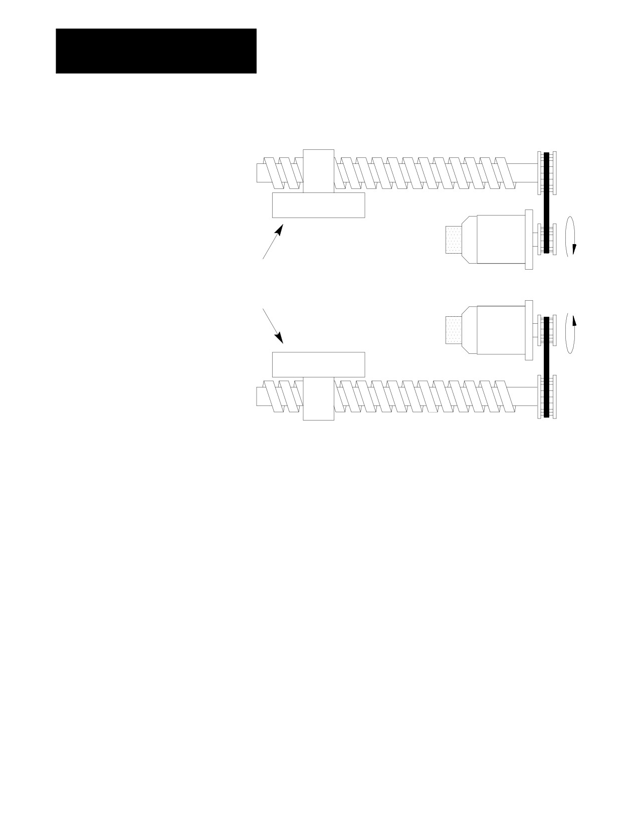
Chapter 30
Using a 9/Series Dual--Processing System
Figure 30.15
Dual- Axis Configuration
Lead screw
Axis 1
Encoder
Servo
motor
Dual Axes - two completely separate
axes responding to the same
programming commands.
Encoder
Servo
motor
Axis 2
Lead screw
The 9/Series control supports two groups of dual axes. This is the total
number of groups allowed on the system for both processes (i.e. two
groups in one process or one group in each process).
Dual--axis operation on dual processing systems is virtually identical to
dual--axis operation on single processing systems (see chapter 20 for
details). The difference occurs on dual processing system when one or
more of the axes in the dual group is configured as a shared axis between
processes.
30.7.1
A dual--axis group is assigned in AMP to a specific process. All axes in
the dual group must be configured to be part of the dual--axis group and
Decoupling a
must be AMPed to be in the same process (called the default process for
Dual- Axis Group
the group). Dual axes can only exist as a dual group in their respective
default process. You can not share a dual group as an axis with another
process. You can only share the independent members of the dual group
with another process once the group is decoupled.
Coupling/Decoupling allows all axes in a dual--axis group to be either:
- coupled as a dual--axis group
- decoupled so each axis in the dual group can be programmed as an
independent axis.
30-38
Chapter 30
Using a 9/Series Dual--Processing System
Coupling/Decoupling is a dual group function. All axes must be in the
dual groups default process before they can be either coupled or decoupled.
When a coupling or decoupling occurs a re-setup occurs of any part
program blocks read into the controls block look ahead buffer. This may
causes a slight hesitation in program execution while the control sets up the
new look ahead buffer.
The system installer uses PAL to determine how a dual--axis group is
decoupled. Refer to your system installer’s documentation for details.
Coupling/Decoupling of the axes can only occur when all axes in the dual
group are not moving (including jogs or part programming, etc...) and are
in the AMP default process for that dual group. If a coupling/decoupling is
attempted during part program execution it occurs between blocks when
interpolation is completed.
Once decoupled the axis park feature that is normally available to the
individual axes of a dual--axis group is no longer available. Axes can be
parked only when the dual--axis group is coupled.
To change the process of a shared axis member of a dual group, you must
first decouple the dual--axis group because couple/decouple is a group
function. When a dual group is decoupled, the axes in the group behave
like completely independent axes. Each dual group member get its own
AMP assigned axis name.
Before a request to decouple a dual--axis is performed, the process
controlling the dual group must be in one of the following states:
- E-Stop
- Cycle Stop (not cycle suspend)
- Manual mode with the shared axis not being positioned
- Executing an M99 in a main program
- Postlude State (established through PAL)
30-39

Chapter 30
Using a 9/Series Dual--Processing System
Other restrictions are as follows:
If the dual- axis is currently:
Then:
performing a manual motion (including
the request to decouple that axis is ignored until the manual
continuous, incremental, or handwheel jog,
motion is completed
homing, jog on the fly, or angled jogs)
being positioned by the PAL axis mover
the request to decouple that axis is ignored until the PAL axis
mover has completed moving the dual--axis
in the active plane and cutter compensation is
the request to decouple that axis is ignored until the plane is
active
changed or cutter compensation is deactivated
used to perform CSS calculations (the dual--axis
the request to decouple that axis is ignored until CSS mode is
has been assigned as the CSS axis and the
canceled
control is currently in CSS mode)
in a process that is performing a jog retract or
the dual axes can not be decoupled. This is independent of
block retrace
whether the dual--axis is involved in the jog retract or block
retrace operation
in a process that is performing a program interrupt
a dual--axis can not be switched into or out of the process
involved in a modal fixed cycle (such as drilling,
the request to change processes is ignored until the cycle is
turning, threading, or 7300 cycles)
canceled
¶ The request for an axis to change processes is ignored until the prohibiting feature is completed or canceled.
Then the change in process only takes place provided the request for the axis change is still true.
30.7.2
When coupled all axes of a dual group are programmed by the name of the
AMPed master axis. Axes in a dual--axis group can be programmed as
Independently Programming
independent axes once they have been decoupled. Once decoupled each
Dual- Axis Members
axis gets its own independent axis name and integrand letter (defined in
AMP) as opposed to the dual--axis group name and integrand used to
program the axis when coupled. For example a dual group consisting of
two axes is programmed with a X axis name. Once the dual group is
decoupled both axes in the dual group are programmed with their own axis
name X and W.
Important: Once an axis has been decoupled from the dual group it still
retains many traits from the original dual group. Features such as acc/dec,
CSS, radius/diameter axis, maximum feedrates, jog feedrates and jog
increments are all adopted from the original group.
Shared axes that have been decoupled from a dual group can change
processes. Once a shared axis is controlled by another process it can not
be recoupled with the dual group until it returns to its original default
process.
Slave axes can be defined in active primary or parallel planes (G17, G18,
or G19) however the plane containing a slave axis can not be activated
unless the dual group is decoupled, and the slave axis is in the process
requesting the plane.
30-40