9/Series CNC Lathe. Operation and Programming Manual - page 24
Chapter 28
Paramacros
Table 28.D (continued)
System Parameters
Parameter #
System Parameter
Page
5731 to 5743
Home Marker Distance
28-31
5751 to 5763
Home Marker Tolerance
28-31
1
These parameters may only have their value received (read-only)
2
These parameters may only have their value changed (write-only)
#2001 to 9499
Tool Offset Tables
These parameters may be changed or simply read through programming.
The values for these parameters are received or entered into the tool offset
tables for geometry and wear (discussed in chapter 3). NO TAG gives the
parameter numbers associated with each table value.
Table 28.E
Tool Offset Table Parameters
Offset
Parameter # for
Parameter # for Wear
Number
Geometry Table
Table
Tool Length
1 to 99
#2701 to 2799
#2001 to 2099
(Axis 1)
Tool Length
1 to 99
#2801 to 2899
#2101 to 2199
(Axis 2)
Tool Length
1 to 99
#8501 to 8599
#8101 to 8199
(Axis 3)
Tool Length
1 to 99
#8601 to 8699
#8201 to 8299
(Axis 4)
Tool Length
1 to 99
#8701 to 8799
#8301 to 8399
(Axis 5)
Tool Length
1 to 99
#8801 to 8899
#8401 to 8499
(Axis 6)
Tool Radius
1 to 99
#2901 to 2999
#2201 to 2299
Tool
1 to 99
#2301 to 2399
N/A
Orientation
#3000
Program Stop With Message (PAL)
Use this parameter to cause a cycle stop operation and display a message
on line 1 of the CRT. Any block that assigns any non-zero value to
parameter 3000 will result in a cycle stop. The actual value assigned to
parameter 3000 is not used. Parameter 3000 is a write-only parameter.
28-17
Chapter 28
Paramacros
When the control executes this block, a cycle stop is performed and the
message “SEE PART PROGRAM FOR MACRO STOP MESSAGE” is
displayed on line 1 of the CRT. This is intended to point out to the
operator an important comment in the program block that assigns a value
to parameter 3000 (see chapter 10 on comment blocks).
For example, programming
#3000=.1 (TOOL NUMBER 6 IS WORN);
causes program execution to stop at the beginning of this block and
displays a message telling the operator to read the comment in the block.
A block reset must be performed before a cycle start will resume normal
program execution.
When this block is executed, it also sets the paramacro alarm PAL flag
($MCALRM) true. Refer to the system installer’s documentation for
details on the effect of this PAL flag.
#3001
System Timer (PAL)
This parameter is referred to as the timer parameter. It is a read-write
parameter. Every 20ms a value of 20 is added to the value of parameter
3001. The value of this parameter is also stored by a PAL flag
($PM20MS) and may be modified or set by the system installers PAL
program. Refer to the system installer’s documentation for details on the
use of this timer. The maximum value of this parameter is 32768ms. Any
value greater than 32768 will cause this parameter to “rollover” to zero and
restart counting again. The value of this parameter is reset to zero every
time power is lost.
#3002
System Clock
This parameter is referred to as a clock parameter and references an hour
counter. It is a read-write parameter with negative value assignments being
illegal. The maximum value for this parameter is 1 year (8760 hours).
The parameter value is maintained when power is lost. It is incremented
by .000005556 every 20 ms.
28-18
Chapter 28
Paramacros
#3003
Block Execution Control 1
Use this parameter to control whether the control ignores single-block
mode and to control when M-codes are executed in a block. The value of
this parameter ranges from 0 to 3, and it is a write-only parameter.
These results occur when parameter 3003 is set to the corresponding
values:
Value:
Single-block mode:
M-codes are executed:
0
can be activated
at the beginning of the program blocks execution
1
requests are ignored
2
can be activated
after the complete execution of the other commands in the
block
3
requests are ignored
#3004
Block Execution Control 2
This parameter determines whether a cycle stop request will be recognized,
whether the feedrate override switch is active, and whether exact stop
mode is available (G61 mode). The range of this parameter is from 0 to 7
and it is a write-only parameter.
NO TAG shows the results of the different values for parameter number
3004. If they are ignored, the control will not allow the feature to be used.
If they are recognized, the feature can be activated in the normal manner.
Table 28.F
Parameter 3004 Values
Value of Parameter
Cycle Stop
Feedrate Override
Exact Stop Mode
0
Recognized
Recognized
Recognized
1
Ignored
Recognized
Recognized
2
Recognized
Ignored
Recognized
3
Ignored
Ignored
Recognized
4
Recognized
Recognized
Ignored
5
Ignored
Recognized
Ignored
6
Recognized
Ignored
Ignored
7
Ignored
Ignored
Ignored
28-19

Chapter 28
Paramacros
#3006
Program Stop With Message
Use this parameter to cause a cycle stop operation and display a message
on line 1 of the CRT. Any block that assigns a new value to the parameter
3006 will result in a cycle stop. Any decimal value may be assigned to this
parameter the value of which is not used.
When the control executes this block, a cycle stop is performed and the
message “SEE (MESSAGE) IN PART PROGRAM BLOCK” is displayed
on line 1 of the CRT. This is intended to point out to the operator an
important comment in a program block (see chapter 10 on comment
blocks). This parameter is a write-only.
For example, programming:
#3006=.1 (Install Tool Number 6);
will cause program execution to stop at the beginning of this block and the
message display the message telling the operator to read the comment in
the block.
#3007
Mirror Image
This parameter is a read-only. It generates an integer that represents, in
binary, what axes are mirrored. For example, if the value of this parameter
was 3, the binary equivalent for this is 00000011. The first digit of this
binary equivalent (reading right to left) corresponds to axis 1, the second is
axis 2, the third is axis 3, etc., up to the number of axes configured in your
system. When a zero is in the binary location for an axis, it indicates that
the axis is not mirrored. If a 1 is in that axis location, that axis is mirrored.
For example, if the parameter #3007 is the integer 11 (binary 00001011), it
indicates axes 1, 2, and 4 are mirrored and axes 3, 5, and 6 are not
mirrored.
0 0 0 0 1 0 1 1
*Axis Number
Listed Below
8
1
7
6
3
2
5
4
Where:
0 indicates axis is not mirrored
1 indicates axis is mirrored
28-20

Chapter 28
Paramacros
This parameter reflects both the programmed and front-panel (external
mirror) status of mirroring on the axes.
#4001 to 4120
Modal Information
These are read-only parameters. They indicate the value of a modal
program word. NO TAG shows the modal program word that applies to
the given parameter number.
Table 28.G
Modal Data Parameters
Parameter Number
Modal Data Value
#4001 to 4021
These correspond to the different G-code Groups 1-21
(see chapter 10) and show what G-code from group is currently active.
4108
Current E--word value
4109
Current F--word value
4113
Most recently programmed M-code
4114
Most recently programmed N--word
4115
Current program number O--word
4119
Current S--word value
4120
Current T--word value
For example, if currently programming in G02 mode at a feedrate of 100,
the parameters would be as follows:
G02 is a group 1 G-code, so its value of 02 is set to parameter number
4001.
The feedrate programmed with an F--word gives parameter number 4109 a
value of 100.
28-21
Chapter 28
Paramacros
#5001 to 5012
Coordinates of End Point
These parameters are read-only. They correspond to the coordinates of the
end point (destination) of a programmed move. These are the coordinates
in the work coordinate system.
5001
Axis 1 coordinate position
5007
Axis 7 coordinate position
5002
Axis 2 coordinate position
5008
Axis 8 coordinate position
5003
Axis 3 coordinate position
5009
Axis 9 coordinate position
5004
Axis 4 coordinate position
5010
Axis 10 coordinate position
5005
Axis 5 coordinate position
5011
Axis 11 coordinate position
5006
Axis 6 coordinate position
5012
Axis 12 coordinate position
The system installer determines in AMP the name (or word) that is used to
define the axis.
#5021 to 5032
Coordinates of Commanded Position
These parameters are read-only. They correspond to the current
coordinates of the cutting tool. These are the coordinates in the work
coordinate system.
5021
Axis 1 coordinate position
5027
Axis 7 coordinate position
5022
Axis 2 coordinate position
5028
Axis 8 coordinate position
5023
Axis 3 coordinate position
5029
Axis 9 coordinate position
5024
Axis 4 coordinate position
5030
Axis 10 coordinate position
5025
Axis 5 coordinate position
5031
Axis 11 coordinate position
5026
Axis 6 coordinate position
5032
Axis 12 coordinate position
The system installer determines in AMP the name (or word) that is used to
define the axis.
28-22
Chapter 28
Paramacros
#5041 to 5052
Machine Coordinate Position
These parameters are read-only. They correspond to the coordinates of the
cutting tool in the machine (absolute) coordinate system.
5041
Axis 1 coordinate position
5047
Axis 7 coordinate position
5042
Axis 2 coordinate position
5048
Axis 8 coordinate position
5043
Axis 3 coordinate position
5049
Axis 9 coordinate position
5044
Axis 4 coordinate position
5050
Axis 10 coordinate position
5045
Axis 5 coordinate position
5051
Axis 11 coordinate position
5046
Axis 6 coordinate position
5052
Axis 12 coordinate position
The system installer determines in AMP the name (or word) that is used to
define the axis.
Position data for the absolute position of an adaptive depth probe is
invalid.
#5061 to 5069 or #5541 to 5552
Skip Signal Position Work Coordinate Position
These parameters are read-only. They correspond to the coordinates of the
cutting tool when a skip signal is received to PAL from a probe or other device
such as a switch. These are the coordinates in the work coordinate system.
5061
Axis 1 coordinate position
5067
Axis 7 coordinate position
5062
Axis 2 coordinate position
5068
Axis 8 coordinate position
5063
Axis 3 coordinate position
5069
Axis 9 coordinate position
5064
Axis 4 coordinate position
5065
Axis 5 coordinate position
5066
Axis 6 coordinate position
Or if your system has more than 9 axes:
5541
Axis 1 coordinate position
5547
Axis 7 coordinate position
5542
Axis 2 coordinate position
5548
Axis 8 coordinate position
5543
Axis 3 coordinate position
5549
Axis 9 coordinate position
5544
Axis 4 coordinate position
5550
Axis 10 coordinate position
5545
Axis 5 coordinate position
5551
Axis 11 coordinate position
5546
Axis 6 coordinate position
5552
Axis 12 coordinate position
The system installer determines in AMP the name (or word) that is used to
define the axis.
28-23
Chapter 28
Paramacros
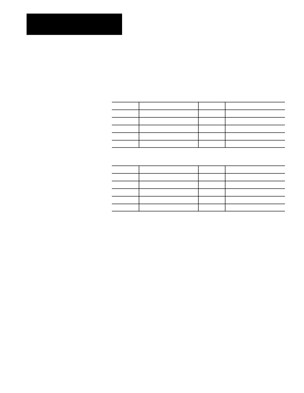
#5071 to 5079 or #5561 to 5562
Skip Signal Position Machine Coordinate System
These parameters are read-only. They correspond to the coordinates of the
cutting tool when a skip signal is received to PAL from a probe or other
device such as a switch. These are the coordinates in the machine
(absolute) coordinate system.
5071
Axis 1 coordinate position
5077
Axis 7 coordinate position
5072
Axis 2 coordinate position
5078
Axis 8 coordinate position
5073
Axis 3 coordinate position
5079
Axis 9 coordinate position
5074
Axis 4 coordinate position
5075
Axis 5 coordinate position
5076
Axis 6 coordinate position
Or if your system has more than 9 axes:
5561
Axis 1 coordinate position
5567
Axis 7 coordinate position
5562
Axis 2 coordinate position
5568
Axis 8 coordinate position
5563
Axis 3 coordinate position
5569
Axis 9 coordinate position
5564
Axis 4 coordinate position
5570
Axis 10 coordinate position
5565
Axis 5 coordinate position
5571
Axis 11 coordinate position
5566
Axis 6 coordinate position
5572
Axis 12 coordinate position
The system installer determines in AMP the name (or word) that is used to
define the axis.
28-24
Chapter 28
Paramacros
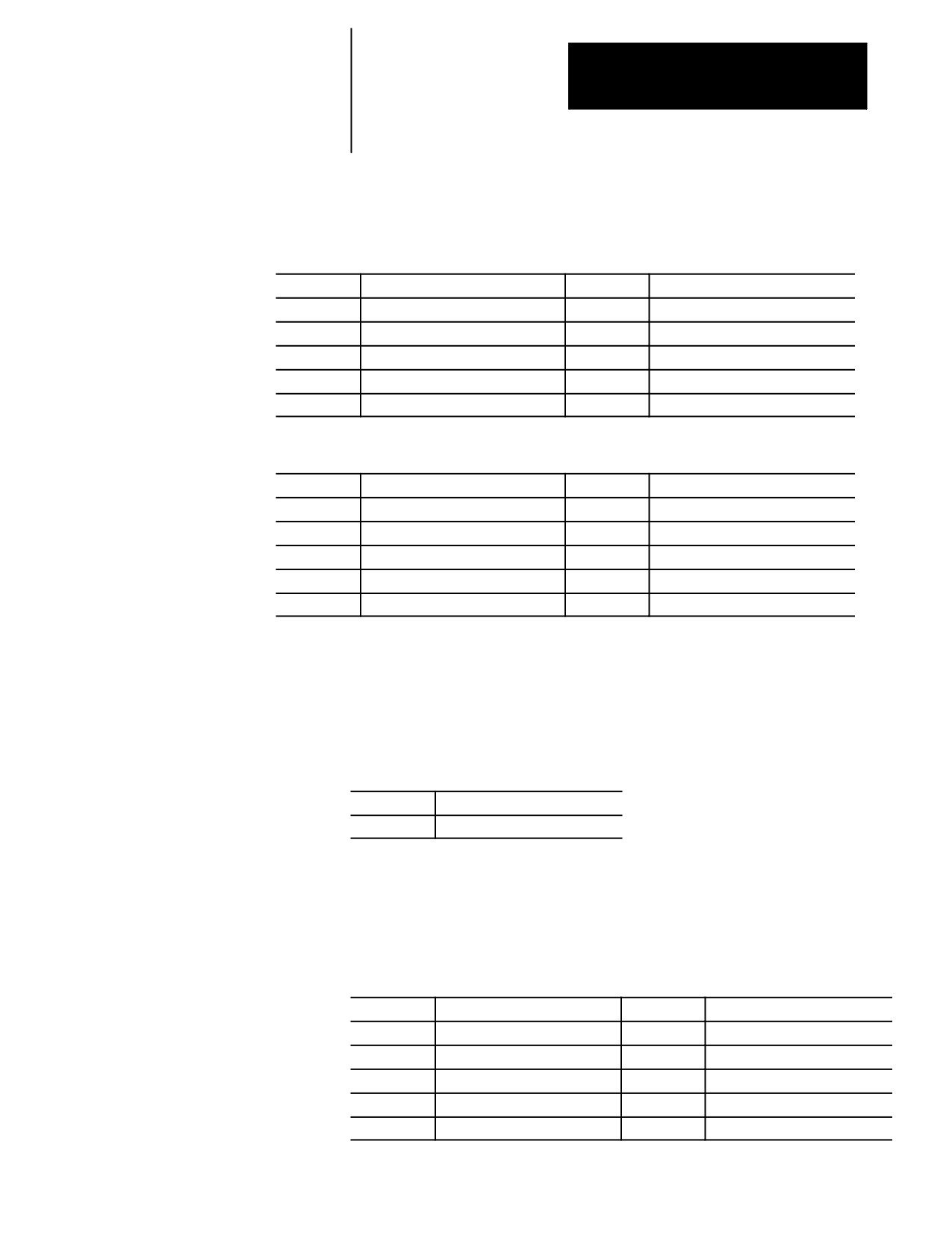
#5081 to 5089 or #5581 to 5592 Active Tool Length Offsets
These are read-only parameters. They correspond to the currently active
tool length offsets (see chapter 20).
5081
Current axis 1 tool length offset.
5087
Current axis 7 tool length offset.
5082
Current axis 2 tool length offset.
5088
Current axis 8 tool length offset.
5083
Current axis 3 tool length offset.
5089
Current axis 9 tool length offset.
5084
Current axis 4 tool length offset.
5085
Current axis 5 tool length offset.
5086
Current axis 6 tool length offset.
Or if your system has more than 9 axes:
5581
Current axis 1 tool length offset.
5587
Current axis 7 tool length offset.
5582
Current axis 2 tool length offset.
5588
Current axis 8 tool length offset.
5583
Current axis 3 tool length offset.
5589
Current axis 9 tool length offset.
5584
Current axis 4 tool length offset.
5590
Current axis 10 tool length offset.
5585
Current axis 5 tool length offset.
5591
Current axis 11 tool length offset.
5586
Current axis 6 tool length offset.
5592
Current axis 12 tool length offset.
#5095 to 5096
Probe stylus Length and Radius
These parameters correspond to the values set in the probing cycle
parameter table discussed in chapter 27. When values are assigned to these
parameters, the current values in the probe table is replaced.
5095
Probe stylus Length
5096
Probe stylus Radius
For details on probe radius and length parameters, see chapter 27 on tool gauging.
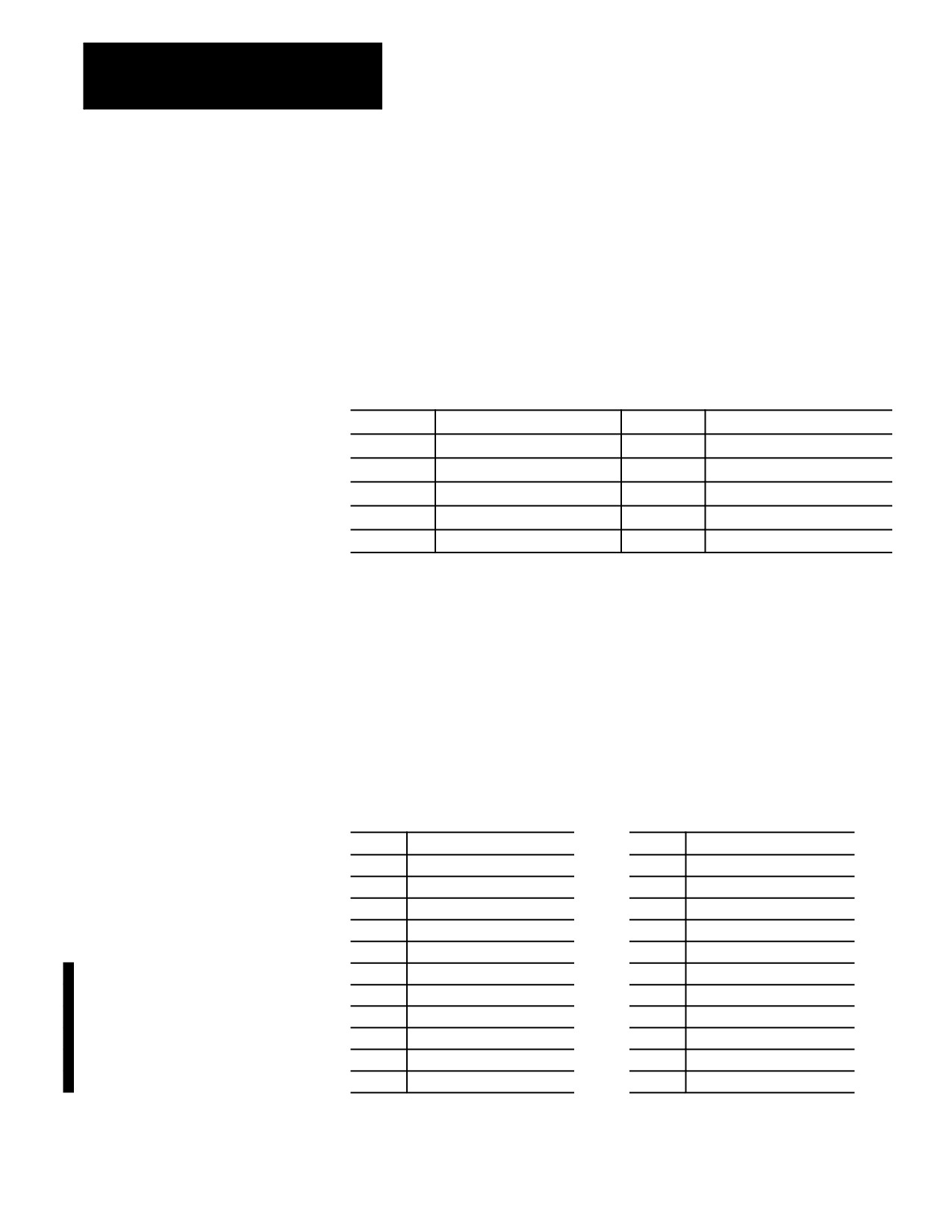
#5101 to 5112
Current Following Error
These parameters are read-only. They correspond to the current following
error for an axis.
5101
Axis 1 following error
5107
Axis 7 following error
5102
Axis 2 following error
5108
Axis 8 following error
5103
Axis 3 following error
5109
Axis 9 following error
5104
Axis 4 following error
5110
Axis 10 following error
5105
Axis 5 following error
5111
Axis 11 following error
5106
Axis 6 following error
5112
Axis 12 following error
28-25
Chapter 28
Paramacros
The system installer determines in AMP the name (or word) that is used to
define the axis. The following error of a system constantly changes. You
can use this parameter to take a “snapshot” of the following error, but the
value that is read may not the current following error of the system.
#5201 to 5212
External Offset Amount
These parameters are read or write. They correspond to the current value
set in the work coordinate table for the external offset (see chapter 3). This
allows the reading of data from the tables and also the setting of data into
the table by assigning values to the parameters.
5201
Axis 1 offset amount
5207
Axis 7 offset amount
5202
Axis 2 offset amount
5208
Axis 8 offset amount
5203
Axis 3 offset amount
5209
Axis 9 offset amount
5204
Axis 4 offset amount
5210
Axis 10 offset amount
5205
Axis 5 offset amount
5211
Axis 11 offset amount
5206
Axis 6 offset amount
5212
Axis 12 offset amount
The system installer determines in AMP the name (or word) that is used to
define the axis. Changes made to the external offset using this paramacro
variable go into effect only after the axis has been re-homed, or power to
the control has been cycled.
#5221 to 5392
Work Coordinate Table Value
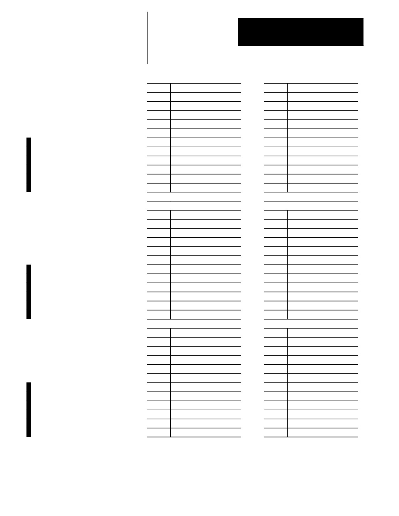
These parameters are read or write. They correspond to the current value set
in the work coordinate table for the G54-G59 work coordinate systems (see
chapter 3). You can read data from the tables and set data into the table by
assigning values to the parameters. The axis names are set in AMP.
5221
G54 Axis 1 Coordinate
5321
G59 Axis 1 Coordinate
5222
G54 Axis 2 Coordinate
5322
G59 Axis 2 Coordinate
5223
G54 Axis 3 Coordinate
5323
G59 Axis 3 Coordinate
5224
G54 Axis 4 Coordinate
5324
G59 Axis 4 Coordinate
5225
G54 Axis 5 Coordinate
5325
G59 Axis 5 Coordinate
5226
G54 Axis 6 Coordinate
5326
G59 Axis 6 Coordinate
5227
G54 Axis 7 Coordinate
5327
G59 Axis 7 Coordinate
5228
G54 Axis 8 Coordinate
5328
G59 Axis 8 Coordinate
5229
G54 Axis 9 Coordinate
5329
G59 Axis 9 Coordinate
5230
G54 Axis 10 Coordinate
5330
G59 Axis 10 Coordinate
5231
G54 Axis 11 Coordinate
5331
G59 Axis 11 Coordinate
5232
G54 Axis 12 Coordinate
5332
G59 Axis 12 Coordinate
28-26
Chapter 28
Paramacros
5241
G55 Axis 1 Coordinate
5341
G59.1 Axis 1 Coordinate
5242
G55 Axis 2 Coordinate
5342
G59.1 Axis 2 Coordinate
5243
G55 Axis 3 Coordinate
5343
G59.1 Axis 3 Coordinate
5244
G55 Axis 4 Coordinate
5344
G59.1 Axis 4 Coordinate
5245
G55 Axis 5 Coordinate
5345
G59.1 Axis 5 Coordinate
5246
G55 Axis 6 Coordinate
5346
G59.1 Axis 6 Coordinate
5247
G55 Axis 7 Coordinate
5347
G59.1 Axis 7 Coordinate
5248
G55 Axis 8 Coordinate
5348
G59.1 Axis 8 Coordinate
5249
G55 Axis 9 Coordinate
5349
G59.1 Axis 9 Coordinate
5250
G55 Axis 10 Coordinate
5350
G59.1 Axis 10 Coordinate
5251
G55 Axis 11 Coordinate
5351
G59.1 Axis 11 Coordinate
5252
G55 Axis 12 Coordinate
5352
G59.1 Axis 12 Coordinate
5261
G56 Axis 1 Coordinate
5361
G59.2 Axis 1 Coordinate
5262
G56 Axis 2 Coordinate
5362
G59.2 Axis 2 Coordinate
5263
G56 Axis 3 Coordinate
5363
G59.2 Axis 3 Coordinate
5264
G56 Axis 4 Coordinate
5364
G59.2 Axis 4 Coordinate
5265
G56 Axis 5 Coordinate
5365
G59.2 Axis 5 Coordinate
5266
G56 Axis 6 Coordinate
5366
G59.2 Axis 6 Coordinate
5267
G56 Axis 7 Coordinate
5367
G59.2 Axis 7 Coordinate
5268
G56 Axis 8 Coordinate
5368
G59.2 Axis 8 Coordinate
5269
G56 Axis 9 Coordinate
5369
G59.2 Axis 9 Coordinate
5270
G56 Axis 10 Coordinate
5370
G59.2 Axis 10 Coordinate
5271
G56 Axis 11 Coordinate
5371
G59.2 Axis 11 Coordinate
5272
G56 Axis 12 Coordinate
5372
G59.2 Axis 12 Coordinate
5281
G57 Axis 1 Coordinate
5381
G59.3 Axis 1 Coordinate
5282
G57 Axis 2 Coordinate
5382
G59.3 Axis 2 Coordinate
5283
G57 Axis 3 Coordinate
5383
G59.3 Axis 3 Coordinate
5284
G57 Axis 4 Coordinate
5384
G59.3 Axis 4 Coordinate
5285
G57 Axis 5 Coordinate
5385
G59.3 Axis 5 Coordinate
5286
G57 Axis 6 Coordinate
5386
G59.3 Axis 6 Coordinate
5287
G57 Axis 7 Coordinate
5387
G59.3 Axis 7 Coordinate
5288
G57 Axis 8 Coordinate
5388
G59.3 Axis 8 Coordinate
5289
G57 Axis 9 Coordinate
5389
G59.3 Axis 9 Coordinate
5290
G57 Axis 10 Coordinate
5390
G59.3 Axis 10 Coordinate
5291
G57 Axis 11 Coordinate
5391
G59.3 Axis 11 Coordinate
5292
G57 Axis 12 Coordinate
5392
G59.3 Axis 12 Coordinate
28-27
Chapter 28
Paramacros
5301
G58 Axis 1 Coordinate
5302
G58 Axis 2 Coordinate
5303
G58 Axis 3 Coordinate
5304
G58 Axis 4 Coordinate
5305
G58 Axis 5 Coordinate
5306
G58 Axis 6 Coordinate
5307
G58 Axis 7 Coordinate
5308
G58 Axis 8 Coordinate
5309
G58 Axis 9 Coordinate
5310
G58 Axis 10 Coordinate
5311
G58 Axis 11 Coordinate
5312
G58 Axis 12 Coordinate
The system installer determines in AMP the name (or word) that is used to
define the axis.
#5630
S-Curve Time per Block
This parameter is read only. The value represents the amount of time
(seconds converted to system scans) for a part program block’s S--Curve filter
where S--Curve Acc/Dec is applied during G47.1 mode. When it is
multiplied by the scan time, the product equals the amount of time required
by the acceleration.
This parameter is only calculated for blocks that have programmed motion
with S--Curve Acc/Dec.
#5631 to 5642
Acceleration Ramps for Linear Acc/Dec Mode
These parameters are read only. They correspond to the active acceleration
ramps in Linear Acc/Dec mode. You can set these parameters by
programming a G48.1 in your part program block. Control Reset, Program
End (M02/M03), or G48 will reset these values to their default AMP values.
For more information about programming G48.x codes, refer to chapter 18 in
your 9/Series CNC Operation and Programming Manual.
5631
Axis 1 acceleration ramp
5637
Axis 7 acceleration ramp
5632
Axis 2 acceleration ramp
5638
Axis 8 acceleration ramp
5633
Axis 3 acceleration ramp
5639
Axis 9 acceleration ramp
5634
Axis 4 acceleration ramp
5640
Axis 10 acceleration ramp
5635
Axis 5 acceleration ramp
5641
Axis 11 acceleration ramp
5636
Axis 6 acceleration ramp
5642
Axis 12 acceleration ramp
28-28
Chapter 28
Paramacros
#5651 to 5662
Deceleration Ramps for Linear Acc/Dec Mode
These parameters are read only. They correspond to the active deceleration
ramps in Linear Acc/Dec mode. You can set these parameters by
programming a G48.2 in your part program block. Control Reset, Program
End (M02/M03), or G48 will reset these values to their default AMP values.
For more information about programming G48.x codes, refer to chapter 18 in
your 9/Series CNC Operation and Programming Manual.
5651
Axis 1 deceleration ramp
5657
Axis 7 deceleration ramp
5652
Axis 2 deceleration ramp
5658
Axis 8 deceleration ramp
5653
Axis 3 deceleration ramp
5659
Axis 9 deceleration ramp
5654
Axis 4 deceleration ramp
5660
Axis 10 deceleration ramp
5655
Axis 5 deceleration ramp
5661
Axis 11 deceleration ramp
5656
Axis 6 deceleration ramp
5662
Axis 12 deceleration ramp
#5671 to 5682
Acceleration Ramps for S-Curve Acc/Dec Mode
These parameters are read only. They correspond to the active acceleration
ramps in S--Curve Acc/Dec mode. You can set these parameters by
programming a G48.3 in your part program block. Control Reset, Program
End (M02/M03), or G48 will reset these values to their default AMP values.
For more information about programming G48.x codes, refer to chapter 18 in
your 9/Series CNC Operation and Programming Manual.
5671
Axis 1 acceleration ramp
5677
Axis 7 acceleration ramp
5672
Axis 2 acceleration ramp
5678
Axis 8 acceleration ramp
5673
Axis 3 acceleration ramp
5679
Axis 9 acceleration ramp
5674
Axis 4 acceleration ramp
5680
Axis 10 acceleration ramp
5675
Axis 5 acceleration ramp
5681
Axis 11 acceleration ramp
5676
Axis 6 acceleration ramp
5682
Axis 12 acceleration ramp
28-29
Chapter 28
Paramacros
#5691 to 5702
Deceleration Ramps for S-Curve Acc/Dec Mode
These parameters are read only. They correspond to the active deceleration
ramps in S--Curve Acc/Dec mode. You can set these parameters by
programming a G48.4 in your part program block. Control Reset, Program
End (M02/M03), or G48 will reset these values to their default AMP values.
For more information about programming G48.x codes, refer to chapter 18 in
your 9/Series CNC Operation and Programming Manual.
5691
Axis 1 deceleration ramp
5697
Axis 7 deceleration ramp
5692
Axis 2 deceleration ramp
5698
Axis 8 deceleration ramp
5693
Axis 3 deceleration ramp
5699
Axis 9 deceleration ramp
5694
Axis 4 deceleration ramp
5700
Axis 10 deceleration ramp
5695
Axis 5 deceleration ramp
5701
Axis 11 deceleration ramp
5696
Axis 6 deceleration ramp
5702
Axis 12 deceleration ramp
#5711 to 5722
Jerk
These parameters are read only. They are only applicable to the current jerk
values when S--Curve Acc/Dec mode is active. You can set these parameters
by programming a G48.5 in your part program block. Control Reset,
Program End (M02/M03), or G48 will reset these values to their default AMP
values. For more information about programming G48.x codes, refer to
chapter 18 in your 9/Series CNC Operation and Programming Manual.
5711
Axis 1 jerk
5717
Axis 7 jerk
5712
Axis 2 jerk
5718
Axis 8 jerk
5713
Axis 3 jerk
5719
Axis 9 jerk
5714
Axis 4 jerk
5720
Axis 10 jerk
5715
Axis 5 jerk
5721
Axis 11 jerk
5716
Axis 6 jerk
5722
Axis 12 jerk
28-30
Chapter 28
Paramacros
#5731 to 5743
Home Marker Distance
These parameters are read only. They correspond to the current home marker
distance. These parameters will contain the distance to marker calculated
when the axis stopped after the home switch went false during the last
homing operation.
5731
Axis 1 home marker distance
5737
Axis 7 home marker distance
5732
Axis 2 home marker distance
5738
Axis 8 home marker distance
5733
Axis 3 home marker distance
5739
Axis 9 home marker distance
5734
Axis 4 home marker distance
5740
Axis 10 home marker distance
5735
Axis 5 home marker distance
5741
Axis 11 home marker distance
5736
Axis 6 home marker distance
5742
Axis 12 home marker distance
#5751 to 5763
Home Marker Tolerance
These parameters are read only. They correspond to the current home marker
tolerance. These parameters will contain the tolerance value at power turn on
and will represent 3/8 of an electrical cycle of the feedback device converted
to current axis programming units (inch/metric, degrees or revolutions).
5751
Axis 1 home marker tolerance
5757
Axis 7 home marker tolerance
5752
Axis 2 home marker tolerance
5758
Axis 8 home marker tolerance
5753
Axis 3 home marker tolerance
5759
Axis 9 home marker tolerance
5754
Axis 4 home marker tolerance
5760
Axis 10 home marker tolerance
5755
Axis 5 home marker tolerance
5761
Axis 11 home marker tolerance
5756
Axis 6 home marker tolerance
5762
Axis 12 home marker tolerance
28.3.4
Paramacro parameters are provided by on the control to allow a means of
communicating values between the PAL program and the part program.
PAL Parameters
This is done by assigning values to specific paramacro parameters or PAL
flags. They are:
Input parameters: Use these parameters to transfer data from PAL to the
part program.
Output parameters: Use these parameters to transfer data from the part
program to PAL. Some applications may, however, use the output flags
to transfer data from PAL to the part program as needed.
28-31
Chapter 28
Paramacros
Input Flags:
There are 4-integer or 3-integer and 32-bit pattern input parameters
available. The part program may only read the values assigned to these
parameters; it may not write values to them. The paramacro input
parameters available to the part programmer are:
#1000 -- #1031 and #1040 -- #1071
These paramacro PAL parameters are used to display the binary
equivalent of the integer assigned to #1032. #1000 is the first bit, #1001
is the second bit, #1002 is the third bit, and so forth up to parameter
#1031 (which is the 32nd bit).
The second set of parameters, #1040 -- #1071, functions the same way.
#1032 -- #1035 and #1072 -- #1075
The control always interprets parameter #1032, #1033, #1034, and
#1035 as integer values regardless of how they are assigned in PAL (as
an integer or on a per bit basis).
#1032 is the only parameter that may
also be interpreted by the control on a per-bit basis using parameters
#1000 - #1031. PAL may always interpret these values on either a
per-bit basis or as integer values.
The second set of parameters, #1072 -- #1075, functions the same way.
See the system installer’s documentation for a detailed description of the
use and operation of these input flags.
Output Flags:
Output flags function almost identically to input flag with one key
difference. Where input flags may only be read by the part program,
output flags may be both read and written to by the part program.
Typically these are used only to output information to the PAL program
from the part program; however, if the available number of input flags is
not sufficient for a given application, the Output flags may also be used to
send information to the part program from PAL.
28-32
Chapter 28
Paramacros
Output flags should not be used as Input flags unless absolutely necessary.
This is because the operator/programmer has the ability to inadvertently
write data to the Output flags, whereas the Input flags cannot be written to
from the control.
Output flags are broken into four 32-bit words. The part programmer can
only assign or read the values of to these flags as integers with the
exception of parameter #1132 which may be assigned as an integer or as a
bit pattern. The paramacro output input parameters available to the part
programmer are:
#1100 -- #1131 and #1140 -- #1171
When the values of these parameters are assigned in the part program,
they should be assigned values of 1 or 0 (as bit patterns). If any integer
value (other then zero) is assigned to these parameters, it will be
interpreted by PAL as a 1. These paramacro PAL parameters are used to
pass the binary equivalent of the integer assigned to #1132. #1100 is the
first bit, #1101 is the second bit, #1102 is the third bit, and so forth up to
parameter #1131 (which is the 32nd bit). When a value is assigned to
#1132, the values assigned to #1100 - #1131 are overwritten with the
binary equivalent of #1132.
The second set of parameters, #1140 -- #1171, functions the same way.
#1132 -- #1135 and #1172 -- #1175
The control always interprets these parameters as integer values. #1132
is the only parameter that may also be interpreted by the part program
on a per-bit basis using parameters #1100 #1131.
The second set of parameters, #1172 -- #1175, functions the same way.
See the system installer’s documentation for a detailed description of the
use and operation of these input flags.
28.3.5
These parameters are available only on dual-process systems (see chapter
Shared Dual-Process
30 for details). These parameters provide a link through which common
data can be passed between the different processes of the machine. The
Parameters (#7100 - 7199)
shared dual-process parameters are paramacro parameter numbers:
#7100 to #7199
These parameters are global. This means that the same set of parameters
can be called by any program, macro, subprogram, or MDI program in any
process.
28-33
Chapter 28
Paramacros
All shared dual-process parameters are saved at power-down. This means
that they retain their value even after power to the control is lost.
Synchronization Problems with Shared Dual-Process Parameters
The programmer must concern himself with timing when changing dual
process paramacro parameters that are used in more than one process.
When you change a shared dual-process paramacro parameter that is to be
used in an additional, currently executing process, you should always use a
synchronization M-code (with setup). This will help prevent timing errors
that can develop when different values than expected are used due to setup
block considerations. Refer to page 30-8 for details on using
synchronization M-codes with shared dual-process parameters.
28.4
There are 3 methods for assigning parameters. They can be assigned by:
Assigning Parameter Values
using arguments (only available for local parameters)
direct assignments
using tables (view or set common parameters, view local parameters)
Assigning Parameters Using Arguments
Arguments may be used only to assign local parameter values. System,
Common, and PAL variables may not be assigned using arguments.
Usually parameters assigned using an argument are variables for a macro.
They are usually specific to the part currently being cut (for example, the
length and diameter of a shaft in a macro that turns a shaft).
The 9/Series control provides 5 sets of local parameters. The first set of
local parameters (those that apply to the main program and any
subprogram call) may not be assigned using arguments. The second
through fifth sets may be assigned by their association to given words in an
argument statement located in a paramacro calling block. NO TAG gives a
listing of arguments and their corresponding parameter numbers.
These arguments assign values to the local parameters associated with the
paramacro called in the same block.
28-34
Chapter 28
Paramacros
Table 28.H
Argument Assignments
(A)
(B)
Word
Parameter
I, J, K
Word
Parameter
Address
Assigned
Set #
Address
Assigned
A
#1
1
I
#4
B
#2
J
#5
C
#3
K
#6
D
#7
2
I
#7
E
#8
J
#8
F
#9
K
#9
H
#11
3
I
#10
I*
#4
J
#11
J*
#5
K
#12
K*
#6
4
I
#13
M
#13
J
#14
Q
#17
K
#15
R
#18
5
I
#16
S
#19
J
#17
T
#20
K
#18
U
#21
6
I
#19
V
#22
J
#20
W
#23
K
#21
X
#24
7
I
#22
Y
#25
J
#23
Z
#26
K
#24
8
I
#25
J
#26
K
#27
9
I
#28
J
#29
K
#30
10
I
#31
J
#32
K
#33
*
If more than one I, J, or K set is programmed in a block, use NO TAG (B) for the parameter
assignment.
28-35
Chapter 28
Paramacros
To enter a value for a parameter # using an argument, enter the word
corresponding to the desired parameter number in a block that calls a
paramacro (for legal argument locations, see specific formats for calling
the macro) followed by the value to assign that parameter. For example:
G65P1001A1.1 B19;
assigns the value of:
1.1 to local parameter #1 in paramacro 1001
19 to local parameter #2 in paramacro 1001
You can specify arguments as any valid parametric expression. For
example:
G246A#100B[#500+10.0]C[SIN[#101]];
Direct Assignment Through Programming
This assignment method applies to Local, Common, System, and PAL
parameters. You can perform direct assignment in Main, Macro, or MDI
programs. Direct assignment is done by setting the parameter equal to
some value in an equation using the “ = ” operator. For example, to assign
a value of 2 to parameter number 100, simply enter the following program
block:
#100=2;
The value to the left of the equals sign must contain the # sign followed by
a legal parameter number. This parameter number may also take on the
form of:
#parameter expression = parameter expression
Example 28.14
Calling Parameter Numbers
#6=1;
#144=1;
#[SIN[#6]]=1;
#[148/2]=1;
#[#6]=1;
All of the above can be used as legal parameter numbers. Any time that a
different parameter is used between the [] symbols, the current value of
that parameter is used for evaluation. For example:
#1=4;
#1=#1+2;
The net result of the above two blocks would be the assignment of a value
of 6 to parameter #1.
28-36
Chapter 28
Paramacros
Example 28.15
Assigning Parameters:
#100=1+1;
#100=5-3;
#100=#3;
#100=#7+1;
#100=#100+1;
You can also assign multiple paramacro parameters in a single block. In a
multiple assignment block, each assignment is separated by a comma. For
example:
#1=10,#100=ROUND[#2+#3],#500=10.0*5;
If you use multiple assignments in the same block, remember:
You can enter as many assignments as can be typed into one block (127
characters maximum).
For local and common parameters, block execution is from left to right.
For example:
#1 = 10,#2=#1+2;
When executed, #1 is 10 and #2 is 12
Once the first paramacro parameter assignment is made in a block, only
assignment syntax is allowed in that block. You cannot program other
information in that block, including programming a G-code. For
example:
#1 = 19.0,G1X10;
will get the error message, “PARAMETER ASSIGNMENT SYNTAX
ERROR”
Only assign the same parameter a value once in each block. For
example:
#1=5,#2=4,#1=6;
would cause the error message “PARAMETER ASSIGNMENT
SYNTAX ERROR” to appear, since #1 is assigned a value twice in the
same block (#1=5 and #1=6).
28-37
Chapter 28
Paramacros
Direct Assignment Through Tables
Use this feature to view or set common parameters and view local
parameters. Assignment through tables is generally used to edit common
parameters.
To edit the values of the common parameters or view the local parameters,
follow these steps.
1.
Press the {MACRO PARAM} softkey.
(softkey level 1)
PRGRAM
OFFSET
MACRO
QUICK
SYSTEM
MANAGE
PARAM
CHECK
SUPORT
FRONT
ERROR
PASS-
SWITCH
PANEL
MESAGE
WORD
LANG
2.
Press the appropriate softkey for the table to be viewed. The macro
parameters are separated in to 4 tables:
{LOCAL PARAM} softkey -- Use this softkey to view the local parameters
of the currently active program (unless the block look ahead has
scanned an upcoming paramacro call). This table includes parameters
numbered 1 - 33. Only one of the five available sets can be viewed on
this screen at any one time. The local parameters reset to zero at the end
of program command (M02 or M30).
{COM-1 PARAM} softkey -- Use this softkey to view or edit the common
parameters numbered 100 - 199 (available to any program, subprogram,
or paramacro program). These common parameters lose their value and
are reset to zero when power to the control is turned off.
{COM-2A PARAM} softkey -- Use this softkey to view or edit the common
parameters (available to any program, subprogram, or paramacro
program) numbered 500 - 519. These common parameters are in
backed up memory. This means that their value is retained even when
power to the control is cycled off. In addition to being in backed up
memory these parameters allow an alphanumeric name to be assigned to
them. This alphanumeric name is only for the purpose of easy
identification. It may not be used to call a common parameter in a
program.
{COM-2B PARAM} softkey -- Use this softkey to view or edit the common
parameters. These common parameters, 520 to 699, are battery-backed
up on the 9/240. On the 9/230, 9/260, and 9/290, parameters 520 to 999
are backed up by the supercapacitor. This means that their value is
retained even when power to the control is cycled off. They differ from
common 2A parameters in that they do not allow an additional name to
be stored in the table with their values.
28-38
Chapter 28
Paramacros
If viewing the local parameter table, do not continue to step 3. If editing
one of the common parameter tables, move on to step 3.
(softkey level 3)
LOCAL
COM-1
COM-2A
COM-2B
PARAM
PARAM
PARAM
PARAM
3.
Select a parameter to change by moving the cursor to the desired
parameter number. Note that the selected parameter is shown in
reverse video. Move the cursor by an entire page by pressing the up
or down cursor key while holding down the [SHIFT] key.
Pressing the {SEARCH NUMBER} softkey allows a rapid search for the
desired parameter number. To use this feature to position the cursor,
press the {SEARCH NUMBER} softkey. Key in the desired parameter
number and press the [TRANSMIT] key. The entered parameter
number is shown in reverse video.
4.
Select and complete the appropriate step to alter the common
parameter values. The 3 options include:
To replace the current value of the selected parameter, press
the {REPLCE VALUE} softkey. Key in the new value for the
parameter and press the [TRANSMIT] key. The old value is
replaced with the value just keyed in.
To zero the current of a selected parameter, press the
{ZERO VALUE} softkey. The message “SELECT VALUE TO
ZERO AND PRESS TRANSMIT” appears. Select the parameter
which is to be set to zero, and press the [TRANSMIT] key. The
current value of the selected parameter is replaced with zero.
To zero all of the parameter values that are found in this
parameter table, press the {0 ALL VALUES} softkey. The prompt
“OK TO ZERO ALL VALUES? (Y/N):” will be displayed. Press
the Y character followed by the [TRANSMIT] key to zero all
parameter values in the table. Press the N character followed by
the [TRANSMIT] key to abort the operation.
- Note that while viewing one of the parameter screens while a
program is executing, any changes to a parameter value on that
screen that are made by the program will not be displayed. By
pressing the {REFRSH SCREEN} softkey, any parameters that
have been changed by the program will be updated to their
current values.
28-39
Chapter 28
Paramacros
5.
If the {COM-2A PARAM} softkey has been pressed (in step 2),
additional softkeys will be available to alter the parameter name.
Select and complete the appropriate step to alter the common
parameter names. The 3 options include:
To edit an existing parameter name or enter a parameter name
for the first time for a local parameter, press the {REPLCE NAME}
softkey. Key in a parameter name for the parameter. A name may
be up to 8 characters long and include any alphanumeric character
with the exception of a few of the special symbols. After the name
is keyed in, press the [TRANSMIT] key. The new parameter name is
displayed next to the value of that parameter.
To clear a parameter name so that no name is displayed next to
the parameter on the screen, press the {CLEAR NAME} softkey.
The message “SELECT NAME TO CLEAR AND PRESS
TRANSMIT” appears. Select the name to clear and press the
[TRANSMIT] KEY. The currently selected parameter name will be
deleted.
To clear all of the parameter names that are found on the
{COMMON 2A} screen for all of the parameters, press the
{CLEAR ALL NM} softkey. The prompt “OK TO CLEAR ALL
NAMES? (Y/N): ” appears. Press Y followed by the [TRANSMIT]
key if it is okay to delete all parameter names. Press N followed
by the [TRANSMIT] key if you want to abort the delete-all-name
operation.
- Note that the parameter name is used only for display purposes.
It has no real function other than to permanently label a
parameter value. The parameter name is retained as is the
parameter value for these parameters even after power is turned
off. The softkeys used to edit the parameter name operate this
way:
(softkey level 3)
SEARCH
REPLCE
ZERO
REPLCE
CLEAR
NUMBER
VALUE
VALUE
NAME
NAME
CLEAR
0 ALL
REFRSH
ALL NM
VALUE
SCREEN
28-40

Chapter 28
Paramacros
Addressing Assigned Parameters
Once you assign a parameter you can address it in a program:
Example 28.16
Addressing Assigned Parameters
#100=5;
#105=8;
G01X#100+5 ;
Axis moves to 10.
G01x[#100+5]
Axis moves to 8
You can also indirectly address parameters with other parameters
Example 28.17
Indirectly Addressing Parameters
#100=101
#101=2.345
G01 X#[#100]; X axis moves to the
contents of #100 which
is #101. #101 has the
value of 2.345.
Backing Up Parameter Values
You can back up the contents of COM1, COM2A, or COM2B individually,
or all of these simultaneously, by using the BACKUP softkeys.
(softkey level 2)
LOCAL
COM-1
COM-2A
COM-2B
PARAM
PARAM
PARAM
PARAM
BACKUP
BACKUP
BACKUP
BACKUP
COM1
COM2A
COM2B
ALL
To back up parameters:
Press this softkey:
#100 -- 199
{BACKUP COM1}
#500 -- 519
{BACKUP COM2A}
#520 -- 999
{BACKUP COM2B}
all of the above
{BACKUP ALL}
1.
Press the appropriate BACKUP softkey.
The system prompts you for a file name.
28-41
Chapter 28
Paramacros
2.
Enter a name for the backup file and press [TRANSMIT].
The system verifies the file name and backs up the selected
parameters into a part program. You can restore these parameters by
selecting and executing that part program.
Important: If part program calculations cause an overflow value, then the
generated backup file contains an M00 and the parameter number followed
by the word “OVERFLOW” as a comment.
28.5
When a paramacro is called, execution of the currently active part program
is halted, and execution is transferred to the macro program. Call
Macro Call Commands
paramacros in the following ways:
Programming G65 in a part program
Programming G66 or G66.1 in a part program
Setting the proper AMP data can call a paramacro with the
programming of specific G--, T--, S--, M--, and B--codes
You can use a paramacro call to call any program that has a program name
of up to 5 numeric digits following the letter O (see chapter 10 on program
names). This program must also contain an M99 end of subprogram or
macro code somewhere in the program before an M02 or M30 is read.
This M99 code causes control to return to the main program or restarts the
paramacro if it is to be executed more than one time.
Important: The M99 code may be programmed anywhere in a paramacro
program block provided no axis words are programmed to the left of the
M99. Any information (other than axis words) programmed to the left of
M99 is executed as part of the paramacro. Any information (including axis
words) programmed in the block to the right of the M99 command is
ignored.
M99X10;
X10 is ignored
X10M99;
Error is generated
M03M99;
M03 is executed
After the control has executed the macro the specified number of times (as
specified by the L--word), execution is returned to the block following the
paramacro call in the calling program.
28-42
Chapter 28
Paramacros
CAUTION: Any edits that are made to a subprogram, or to a
paramacro program (as discussed in chapter 5) that has already
been called for automatic execution, are ignored until the calling
program is disabled and reactivated. Subprograms and paramacros
are called for automatic execution the instant that the calling
program is selected as active (as discussed in chapter 7).
28.5.1
Use this format for calling a paramacro using the G65 command:
Non-Modal Paramacro Call
G65 P_ L_ A_ B_;
(G65)
Where :
Is :
P
Indicates the program number of the called macro. P ranges from 1 - 99999.
L
Programs the number of times the macro will be executed. L ranges from 1 - 9999,
and may be expressed as any valid parametric expression. If not specified, the
control uses a default value of 1.
A-Z
Optional argument statements. May be programmed using any letter from A to Z
excluding G, L, N, O, or P. Used to assign numeric values to parameters in the
paramacro (see NO TAG). Arguments may be specified as any valid parametric
expression.
The G65 command is non-modal. The macro is executed only at the time
the control executes the G65 block. The control calls the macro specified
by the G65 block as programmed by the P--word.
The control executes this macro until the control reaches an M99 macro
return code. The macro then returns to the next unexecuted sequential
block in the calling program unless the macro has not been repeated the
number of times as determined by the L--word. If this is the case, the
macro re-executes.
You can define the L--word or any optional argument statements in a G65
block by using any valid parametric expression. For example:
G65 P1002 L[#1+1] A[12*6] B[SIN[#101]];
28-43
Chapter 28
Paramacros
28.5.2
Use this format for calling a paramacro using the G66 command:
Modal Paramacro Call (G66)
G66 P_ L_ A_ B_;
Where :
Is :
P
Indicates the program number of the called macro. P ranges from 1 - 99999.
L
Programs the number of times the macro will be executed after each motion block
that follows the G66. L ranges from 1 - 9999, and may be expressed as any valid
parametric expression. If not specified, the control uses a default value of 1.
A-Z
Optional argument statements. May be programmed using any letter from A to Z
excluding G, L, N, O, or P. Used to assign numeric values to parameters in the
paramacro (see NO TAG). Arguments may be specified as any valid parametric
expression.
The G66 command is modal and remains in effect until canceled with a
G67 block. The macro programmed by the P--word in the G66 block is not
executed when the G66 block is read. The control delays macro execution
to any block following the G66 command that contains a motion
command.
When the control encounters a motion block (even if this block is
contained in a different macro) following the G66 block, it executes the
motions called for by that block first. After that block has been executed,
the control then calls the macro specified by the G66 block.
The control executes this macro until the control reaches an M99 macro
return code. The macro then returns to the next unexecuted sequential
block in the calling program unless the macro has not been repeated the
number of times as determined by the L--word. If this is the case, the
macro re-executes.
Each time that a specific macro is called by a motion command, it is
executed the number of times programmed with the L--word. All local
variables remain at their current value throughout the program unless
replaced, the control is reset, E-Stop is reset, or the control encounters an
M02 or an M30 code in a program.
An L--word programmed with a G66 macro call cannot be replaced without
reprogramming the entire G66 block with the new L--word. An L--word is
active each time the macro is called by the main program and causes the
macro to be executed the number of times programmed with L.
You can define the L--word or any optional argument statements in a G66
block by using any valid parametric expression. For example:
G66 P1002 L[#1+1] A[12*6] B[SIN[#101]];
28-44

Chapter 28
Paramacros
Unlike nonmodal macro calls, the G66 macro call repeats automatically
after any axis move until cancelled by a G67 block. This also applies to
nested macros. When the control begins execution of the nested macro
1002 in the program below, each axis move in the nested macro also calls
for the execution of the macro 1001.
Example 28.18
Modal Macro Call
N0100G66P1001;
N0200G65P1002;
In Example 28.18, after the complete execution of the macro 1002, the
macro 1001 is called. Any motion blocks in macro 1002 will cause macro
1001 to be executed.
Example 28.19
Modal Macro Operation
(MAIN);
O1000;
NO10G90;
N020G66P1001L2A1.1;
Parameter #1 is set at 1.1 in macro 1001.
N030X1;
X Axis is moved 1 unit and then macro 1001 is called and
executed 2 times.
N040Z.25
Z Axis is moved .25 units and then macro 1001 is called and
executed 2 times.
N050G66P1002A2;
Parameter #1 is set at 2. in macro
1002.
N060X1.;
X axis is moved 1 unit then macro
1002 is called and
executed once.
N070G67;
Macro 1002 is canceled.
N090G67;
Macro 1001 is canceled.
N100M30;
(MACRO);
O1001;
N200Z#1;
Z Axis moves an amount equal to the current value for
parameter #1
N210#1=1.7
Parameter #1 for macro 1001 is set at 1.7.
N220M99;
Macro end.
(MACRO);
O1002;
N300Z#1;
Z Axis moves an amount equal to the current value set
parameter #1 (in this case always 2 units). Macro 1001 is
called and executed twice.
N310M99;
Macro end.
28-45
Chapter 28
Paramacros
Important: When the control executes block N040, the original value as
set in block N020 for parameter number 1 is ignored, and the most current
value (1.7) is used. The first time macro 1001 is executed, Z moves 1.1
units. The second time macro 1001 is executed, Z moves 1.7 units.
28.5.3
Use this format for calling a paramacro using the G66.1 command:
Modal Paramacro Call
G66.1 P_ L_ A_ B_;
(G66.1)
Where :
Is :
P
Indicates the program number of the called macro. P ranges from 1 - 99999.
L
Programs the number of times the macro will be executed. L ranges from 1 - 9999,
and may be expressed as any valid parametric expression. If not specified, the
control uses a default value of 1.
A-Z
Optional argument statements. May be programmed using any letter from A to Z
excluding G, L, N, O, or P. Used to assign numeric values to parameters in the
paramacro (see NO TAG). Arguments may be specified as any valid parametric
expression.
The G66.1 command is modal and is executed in the same manner as the
G66 with these exceptions:
The macro programmed by the P--word in the G66 block is not executed
when the G66 block is read, whereas the macro programmed by the
G66.1 is executed when G66.1 is read.
The macro is executed in any and all blocks following the G66.1, not
just after motion blocks, except for paramacro command blocks such as
assignment, goto, etc.
Axis motion cannot be generated by normal program blocks. Axis
motion can be generated only in the program called by G66.1.
The following words, when programmed after the G66.1 block, are used
as argument assignments:
N: when programmed after a word other than N or O, is used as
assignment #14.
G: The last G-code programmed in a block will be used as an argument
statement for parameter #10. All other G-codes are interpreted as
normal.
L: Assigns value to parameter #12
P: Assigns value to parameter #16
All other argument assignments are interpreted as listed in NO TAG.
28-46