9/Series CNC Lathe. Operation and Programming Manual - page 22
Chapter 26
Drilling Cycles
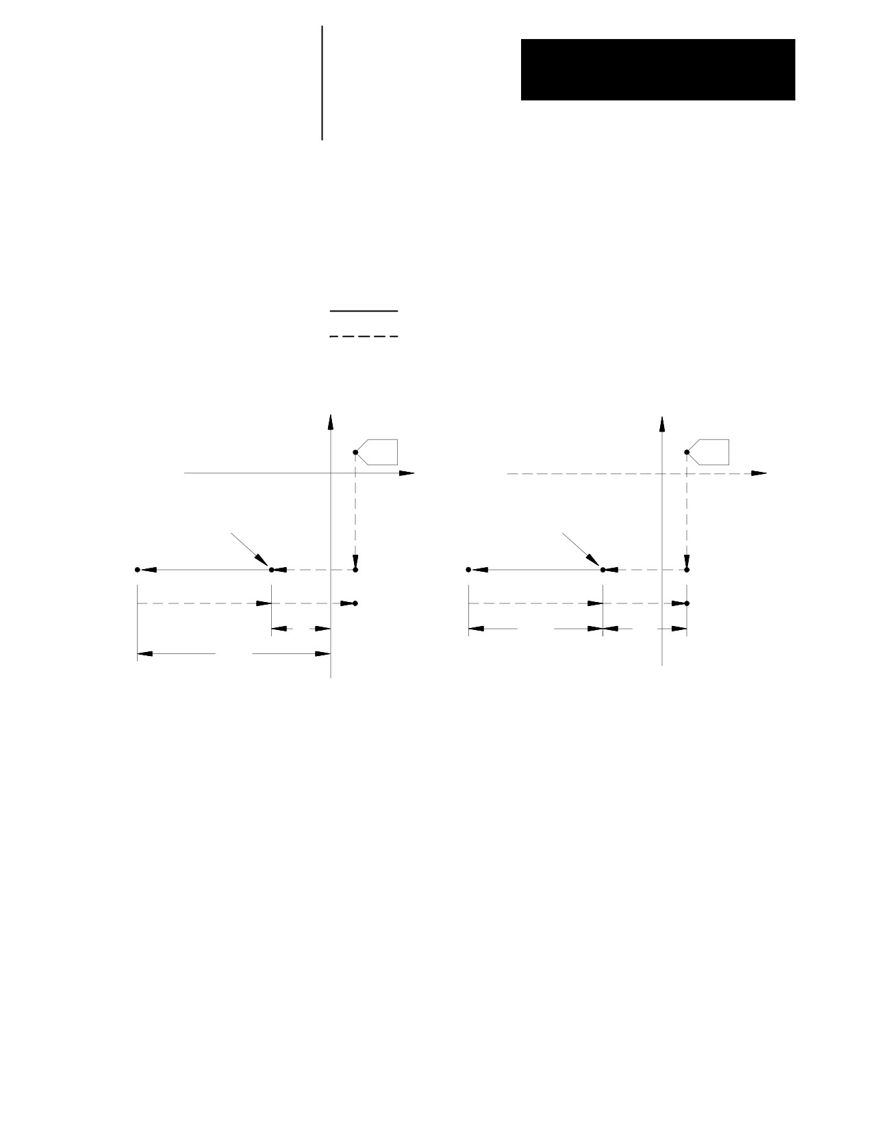
Figure 26.2 shows typical drilling cycle motions in absolute (G90) or
incremental (G91) mode. Note the changes in how the R point and Z level
are referenced.
Figure 26.2
Drilling Cycle Parameters in G90 and G91 Modes
Cutting feed
Rapid feed
G90 Absolute Mode
G91 Incremental Mode
0
0
Z
Z
R point level
R point level
R
Z
R
Z
26-5
Chapter 26
Drilling Cycles
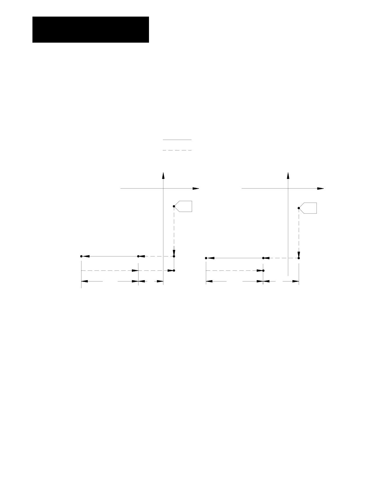
Figure 26.3 shows the two different modes available for selecting the
return level in the Z axis after the hole has been drilled. These two modes
are selected with G98 (which returns to the same level the cycle started at)
and G99 (which returns to the level defined by the R point).
Figure 26.3
Drilling Cycle Parameters in G98 or G99 Modes
Cutting feed
Rapid feed
G98 Initial point return
G99 R - Point return
X
X
Z
Z
0
0
R point level
R point level
Z
R
Z
R
Important: If your system is configured to use lathe G code system “A”
(selected in AMP), you can not program a G98 or G99 to change between
initial and R point returns. Lathes with G code system “A” always use the
R point return type (as if in G99 mode).
Important: In the following sections, figures and examples are assumed
to be programmed in the incremental mode (G91) and initial point return
mode (G98).
26-6
Chapter 26
Drilling Cycles
26.3
This section provides a detailed explanation of each parameter you can
program for the drilling cycles. Some parameters are not valid with all
Parameters
cycles; see the specific description of each cycle. To alter drilling cycle
operation parameters, see section 26.5.
These drilling cycle parameters are described below:
X__Y__Z__R__ I__J__K__ P__F__L__Q__D__S__;
Where :
Is :
X
specifies the location of the hole position in the selected plane. In the absolute mode
(G90), program the hole position using the coordinate values in the active coordinate
system. In incremental mode (G91), program the hole position using the distance from the
current tool position to the required hole position. This parameter is affected by radius or
diameter programming modes.
Z
defines the hole bottom. In absolute mode (G90), program the hole bottom level using the
coordinate value in the active coordinate system. In the incremental mode (G91), program
the distance from the R point level to the hole bottom level.
R
defines the R point level. In the absolute mode (G90), program the R point level as a
coordinate value in the active coordinate system. In the incremental mode (G91), program
the R point level by the distance from the initial point level to the R point level.
I,
J,
K
define the shift amount for G86.1 and G87.
P
defines the dwell period at hole bottom. P programs the dwell in the same way as G04:
seconds if in feedrate mode (G94), spindle revolutions if in revolution mode (G95). (The
allowable dwell time range in seconds is 0.001-99999.99. The allowable dwell range in
revolutions is also 0.001-99999.999.) The P-word does not apply in all drilling cycles.
F
defines the cutting feedrate. If this parameter is not specified, the control uses the
currently active feedrate for the cutting feedrate. For G84.2 and G84.3, F = tap thread lead
in inches/mm per revolution.
L
defines the number of times the drilling cycle is repeated. The maximum number of
repeats is 9999.
· In absolute mode, the control drills in the same location the number of times specified by
the L-word.
· In incremental mode, the L-word drills the number of holes specified by the L-word at
equally spaced positions, determined by axis positioning parameters X and Y.
· If an L0 is programmed, the control decodes the milling cycle information, but does not
execute the drilling cycle. If no L-word is programmed, the control defaults to L1.
Q
In G83, Q defines the infeed amount for each move made in the hole.
In G86.1 and G87, Q defines the shift amount (as do I, J, and K).
In G84.2 and G84.3, Q defines the angle at which to orient the spindle before starting the
tap. If you don’t program the Q-word, the spindle is not oriented before the tap begins. This
means that the hole is not retappable unless a Q-word is programmed in the cycle block.
The spindle is brought to a stop prior to the initiation of the tapping phase even if Q is not
programmed; this happens after the move to the R-plane.
D
defines the return spindle speed so that, if you want, the tap-out move can be performed
faster or slower than the tap-in. Tool selection by D-word is not possible while in the
solid-tapping mode.
S
defines spindle speed in rpm.
26-7
Chapter 26
Drilling Cycles
26.4
Drilling cycles G83.1, G84.1, G86.1 and G81-G89 are modal, which
means they remain active until you program a G-code that cancels the
Drilling Cycle Operations
drilling cycle. Certain drilling cycles can, therefore, be repeated at
different positions without having to re-program all the parameters
associated with a given operation.
Similarly, any parameters specified in the block calling the drilling cycle
remain active until the cycle is cancelled, or until they are re-programmed
in a following block. L-words do not remain active and, instead, designate
the number of times the drilling cycle is repeated.
G00-G03, G33, G34 or G80 cancel drilling cycle mode.
Important: Start the tool rotating with appropriate programming before
the control executes a drilling cycle block.
CAUTION: On systems with more than one spindle, the
controlling spindle code determines which spindle (and its
related spindle modal M-codes) is active during drilling cycles.
All references to spindle activities (orient, reversal, etc.)
described in this chapter apply only to the controlling spindle.
See chapter 17.
(G80): Cancel or End Fixed
The format for the G80 cancel or end fixed cycles is:
Cycles
G80;
Programming a G80 cancels the currently active drilling cycle mode. G00,
G01, G02, G03, G33 or G34 also cancel any active drilling cycle.
If drilling cycles are canceled with a G80, program execution returns to the
mode which was in effect when the cycles were last turned on, for
example, G00 - G03 or G33, G34.
26-8
Chapter 26
Drilling Cycles
(
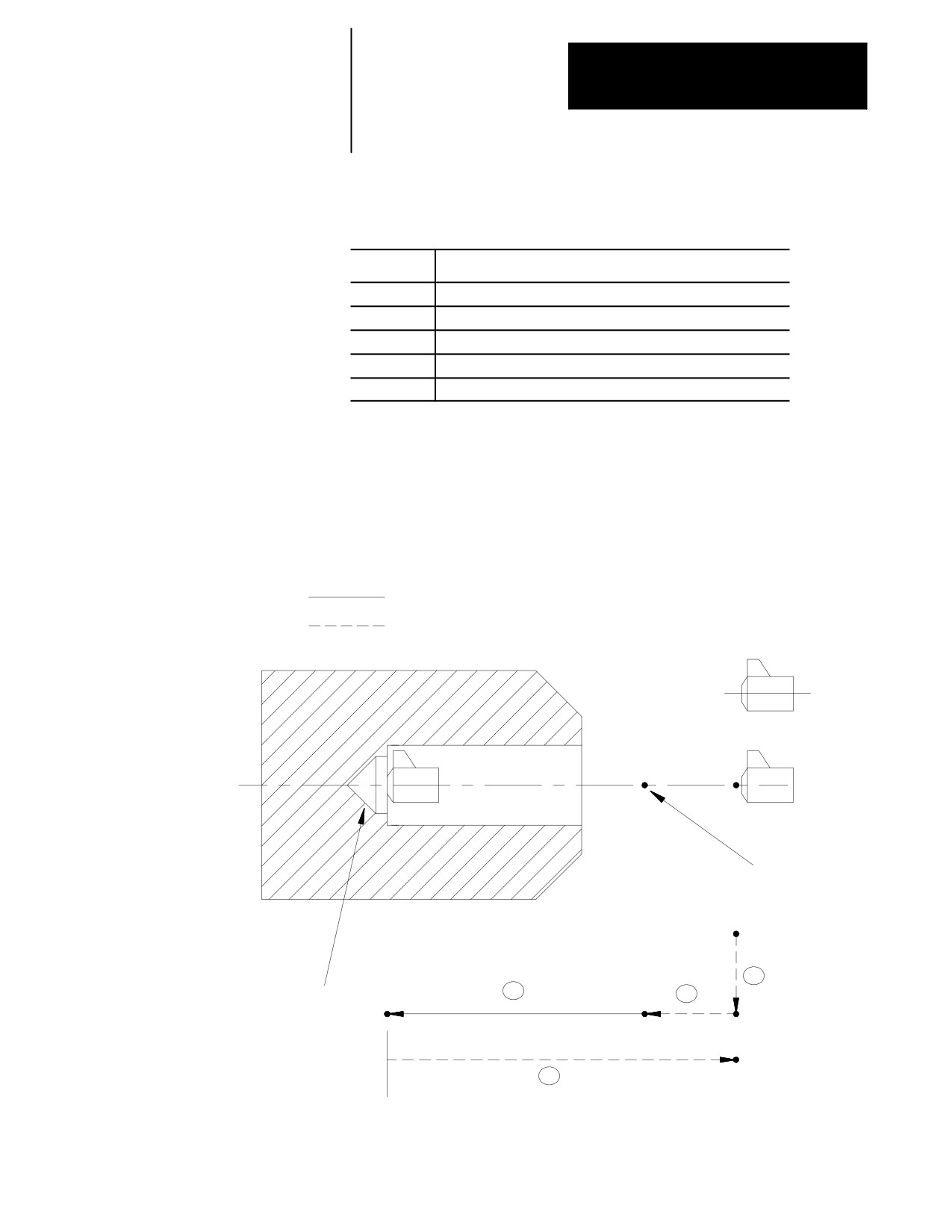
G81): Drilling Cycle, No
The format for the G81 cycle is:
Dwell/Rapid Out
G81X__Z__R__F__L__;
Where :
Is :
X
specifies location of the hole.
Z
defines the hole bottom.
R
defines the R point level.
F
defines the cutting feedrate.
L
defines the number of times the drilling cycle is repeated.
See page 26-7 for a detailed description of these parameters.
Important: The programmer or operator must start spindle or live tool
rotation.
Figure 26.4
G81: Drilling Cycle without Dwell
Cutting feed
Rapid feed
Initial point
level
R point level
1
3
2
Hole bottom
Z
R
4
26-9
Chapter 26
Drilling Cycles
In the G81 drilling cycle, the control moves the axes in this manner:
1.
The tool rapids to the initial point level above the hole location.
2.
The drilling tool then rapids to the R point level, slows to the
programmed cutting feedrate and begins the drilling operation.
3.
The drilling tool continues to drill at the programmed feedrate until it
reaches the depth of the hole as programmed with the Z-word.
4.
The control retracts the drilling tool at a rapid feedrate to the initial
point level as determined by G98.
When the single block function is active, the control stops axis motion
after steps 1, 2 and 4.
(G82): Drill Cycle,
The format for the G82 cycle is:
Dwell/Rapid Out
G82X__Z__R__P__F__L__;
Where :
Is :
X
specifies location of the hole.
Z
defines the hole bottom.
R
defines the R point level.
P
defines the dwell period at hole bottom.
F
defines the cutting feedrate.
L
defines the number of times the drilling cycle is repeated.
See section 27.3 for a detailed explanation of these parameters.
Important: The programmer or operator must start spindle or live tool
rotation.
26-10
Chapter 26
Drilling Cycles
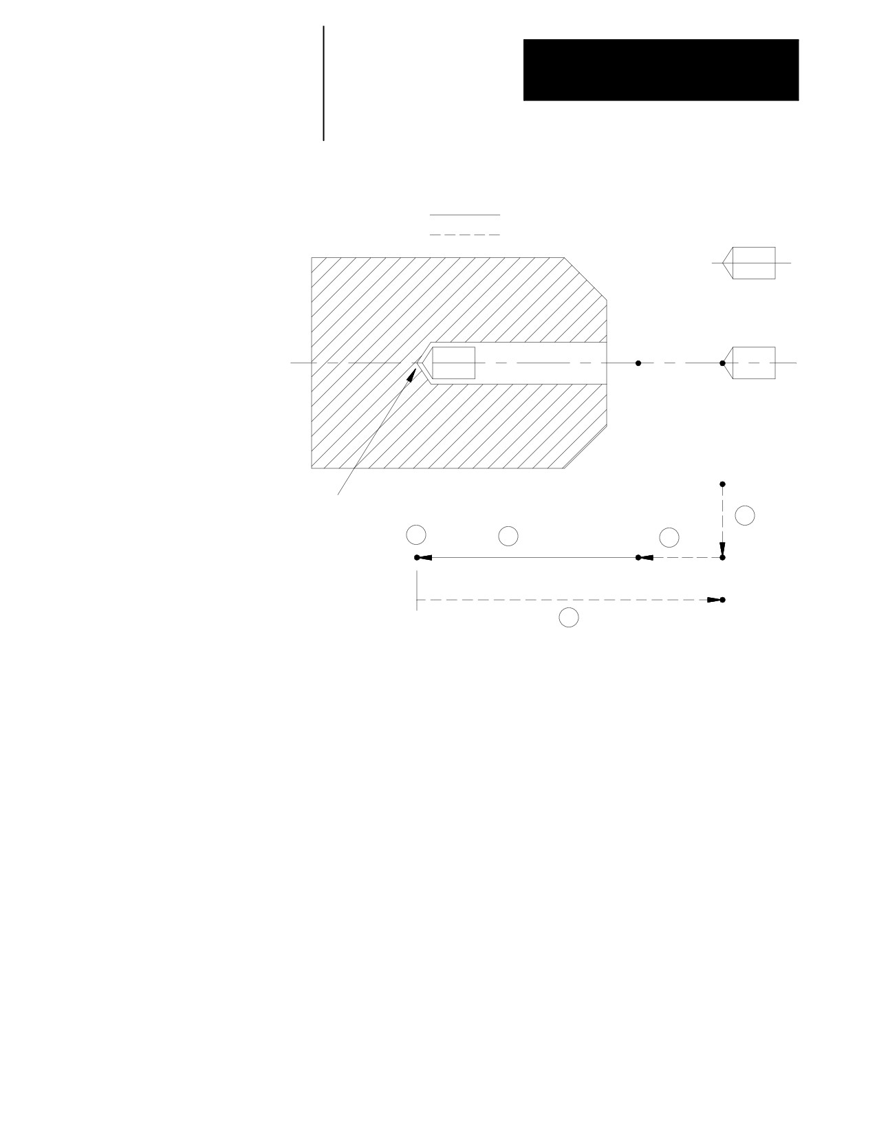
Figure 26.5
G82: Drilling Cycle, Dwell/Rapid Out
Cutting feed
Rapid feed
R point level
initial point
level
Hole bottom
1
4
3
2
Z
R
Dwell at hole bottom
5
In the G82 drilling cycle, the control moves the axes in this manner:
1.
The tool rapids to initial point level point above the hole location.
2.
The drilling tool then rapids to the R point level, slows to the
programmed cutting feedrate and begins the drill operation.
3.
The cutting tool drills at the programmed feedrate to the
pre-programmed depth of the hole (defined by the Z-word in the
boring cycle block).
4.
If a value was programmed for the P parameter, the drilling tool
dwells after it reaches the bottom of the hole.
5.
After the drilling tool reaches the hole bottom and the dwell is
completed, the drilling tool is retracted at a rapid feedrate to the
initial point level as determined by G98.
When the single block function is active, the control stops axis motion
after steps 1, 2 and 5.
26-11
Chapter 26
Drilling Cycles
(G83): Deep Hole Drilling
The format for the G83 cycle is:
Cycle
G83X__Z__R__Q__F__L__;
Where :
Is :
X
specifies location of the hole.
Z
defines the hole bottom.
R
defines the R point level.
Q
defines the infeed amount for each step into the hole.
F
defines the cutting feedrate.
L
defines the number of times the drilling cycle is repeated.
See page 26-7 for a detailed description of these parameters.
Important: The programmer or operator must start spindle or live tool
rotation.
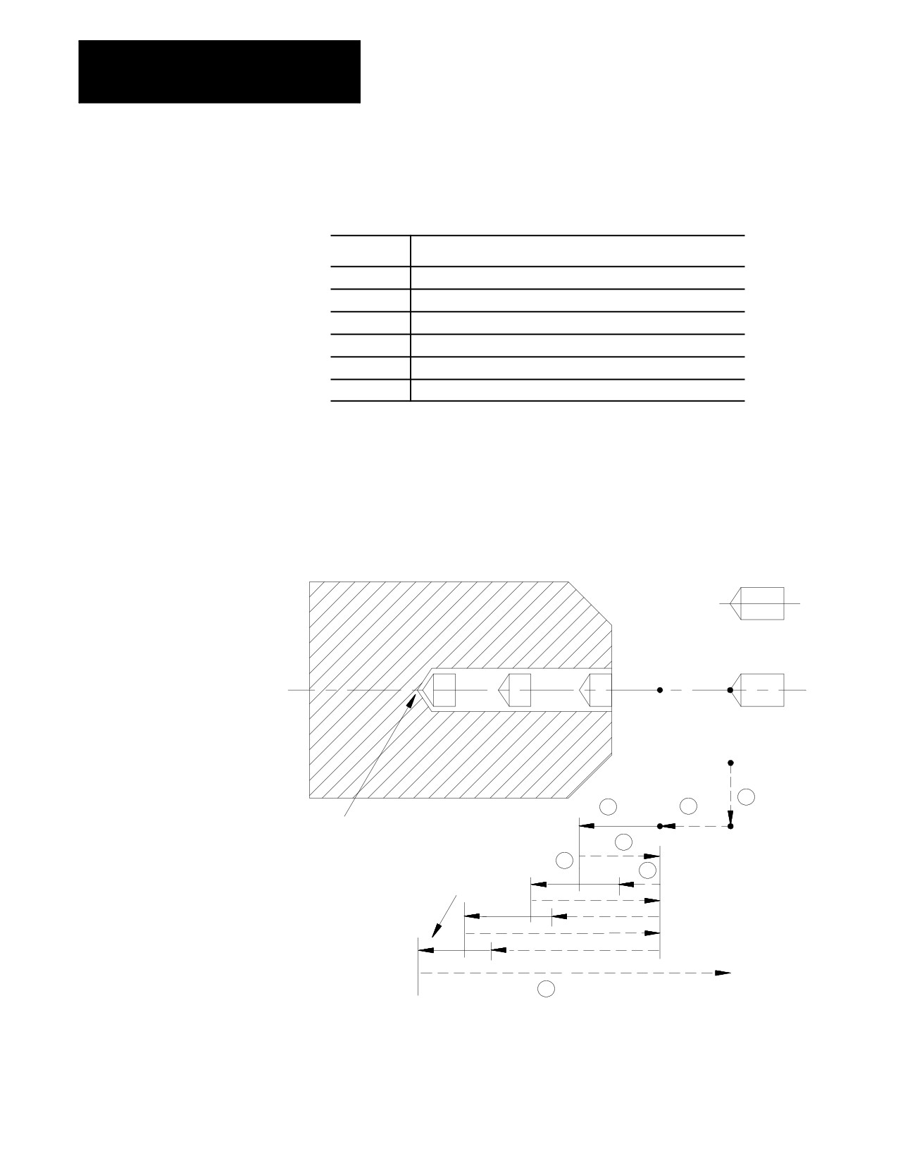
Figure 26.6
G83: Deep Hole Drilling Cycle
initial point
level
R point level
1
3
2
Q
R
Hole bottom
4
Moves to hole bottom
when Q is larger than
6
5
remaining depth
Q
d
Q
d
d
7
26-12
Chapter 26
Drilling Cycles
In the G83 drilling cycle, the control moves the axes in this manner:
1.
The tool rapids to initial point level above the hole location.
2.
The drilling tool then rapids to the R point level, slows to the
programmed cutting feedrate and begins the deep hole drilling
operation.
3.
During the drilling operation, the control infeeds the drilling tool by
an amount Q, as programmed in the G83 block.
4.
The drilling tool retracts at a rapid feedrate to the R point level.
5.
The control feeds the drilling tool at rapid feedrate to a distance d
above the level drilled in the previous infeed. The amount d is
specified by the system installer, or can be set by the operator as
described in section 27.5. This intermittent feed simplifies chip
disposal and permits a very small retraction amount to be set in deep
hole drilling.
6.
The drilling tool slows to the cutting feedrate again and infeeds an
amount Q + d.
7.
The cutting tool is then retracted at a rapid feedrate to the initial point
level as determined by G98.
When the single block function is active, the control stops axis motion
after steps 1, 2 and 7.
(
G83.1): Deep Hole Peck
The format for the G83.1 cycle is:
Drilling Cycle with Dwell
G83.1X__Z__R__Q__P__F__L__;
Where :
Is :
X
specifies the location of the hole position in the selected plane.
Z
defines the hole bottom.
R
defines the R point level.
Q
defines the infeed amount for each step into the hole.
P
defines the dwell period at hole bottom.
F
defines the cutting feedrate.
L
defines the number of times the drilling cycle is repeated.
See page 26-7 for a detailed description of these parameters.
Important: The programmer or operator must start spindle or live tool
rotation.
26-13
Chapter 26
Drilling Cycles
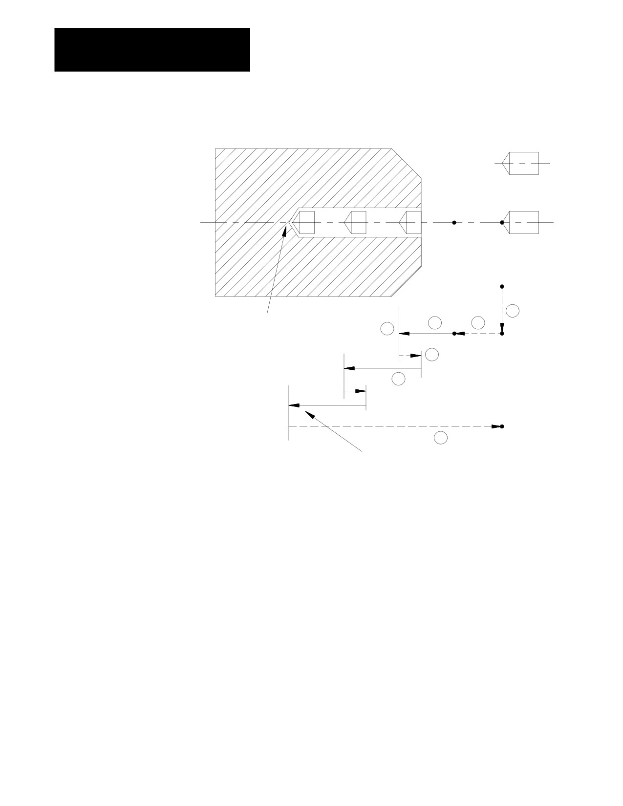
Figure 26.7
G83.1: Deep Hole Peck Drilling Cycle with Dwell
R point level
Initial point
level
1
Hole bottom
3
2
4
Q
R
5
Q
d
6
d
7
Moves to hole bottom when Q is
larger than remaining depth
In the G83.1 peck drilling cycle, the control moves the axes in this manner:
1.
The tool rapids to the initial point level above the hole location.
2.
The drilling tool then rapids to the R point level, slows to the
programmed cutting feedrate and begins the drilling operation.
3.
During the drilling operation, the control infeeds the drilling tool by
an amount Q, as programmed in the drilling cycle.
4.
If a value was programmed for the P parameter, the drilling tool
dwells after it reaches the bottom of the hole.
5.
It then retracts by an amount d at a rapid feedrate. The amount d is
specified by the system installer, or can be set by the operator as
described on page 26-38. This intermittent feed simplifies chip
disposal and permits a very small retraction amount to be set in peck
drilling.
26-14
Chapter 26
Drilling Cycles
6.
After the drilling tool retracts an amount d, it then resumes drilling at
the cutting feedrate to a depth d + Q.
This retraction and extension continues until the drilling tool reaches
the depth of the hole as programmed with the Z-word in the drilling
cycle block.
7.
The drilling tool then retracts at a rapid feedrate to the initial point
level as determined by G98.
When the single block function is active, the control stops axis motion and
awaits “cycle start” after steps 1, 2 and 7.
(G84):
Right-Hand Tapping
Use this cycle to cut right-handed threads. The format for the G84 cycle
Cycle
is:
G84X__Z__R__P__F__L__;
Where :
Is :
X
specifies location of the hole.
Z
defines the hole bottom.
R
defines the R point level.
P
defines the dwell period at hole bottom.
F
defines the cutting feedrate and represents the thread lead along the drilling axis
(Z in this manual). It is mandatory when cutting any threads. The control
interprets the F-word as the number of threads per inch or millimeter.
L
defines the number of times the drilling cycle is repeated.
See section 27.3 for a detailed description of these parameters.
Important: When programming and executing a G84 tapping cycle,
remember:
the programmer or operator must start spindle or live tool rotation
override usage - the control ignores the feedrate override switch and
clamps override at 100 percent
during tapping, the feedrate override switch and the feedhold feature are
both disabled; cycle stop is not acknowledged until the end of the return
operation
26-15
Chapter 26
Drilling Cycles
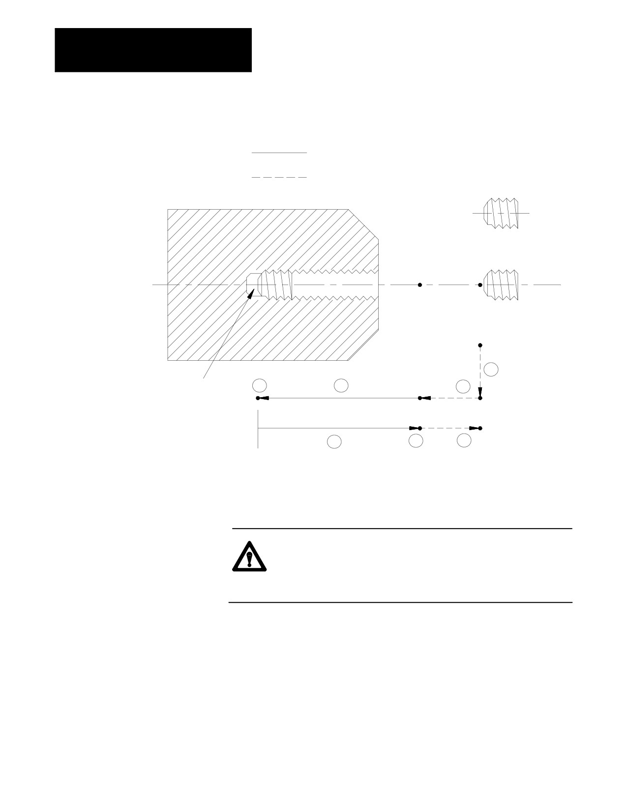
Figure 26.8
G84: Right-Hand Tapping Cycle
Cutting feed
Rapid feed
R point level
Initial point
level
1
Hole bottom
4
3
2
Z
R
Spindle or live tool rotation
direction reversed at hole
bottom
5
6
7
Spindle or live tool rotation
in the forward direction
In the G84 right-hand tapping cycle, the control moves the axes in this
manner:
CAUTION: The programmer or operator must set the direction
of spindle rotation for tap-in. The control forces the proper
spindle direction for the tap-out, but uses the programmed
spindle direction for the tap-in.
1.
The tool rapids to initial point level above the hole location.
2.
The threading tool then rapids to the R point level, slows to the
programmed cutting feedrate and begins the tapping operation.
3.
During the tapping operation, the control infeeds the threading tool to
the depth and at the feedrate programmed in the tapping cycle.
26-16

Chapter 26
Drilling Cycles
4.
If a value was programmed for the P parameter, the threading tool
dwells after it reaches the bottom of the hole, and after the spindle has
been commanded to reverse.
The spindle or live tool reverses to the counterclockwise direction.
5.
The threading tool retracts at the cutting feedrate to the R point.
6.
If a value was programmed for the P parameter, the threading tool
dwells after it reaches the R point. Dwells may be ignored if the
system installer has chosen to do so in AMP.
The spindle or live tool direction is reversed to clockwise.
7.
With G98 active, the cutting tool then accelerates to the rapid feedrate
and retracts to the initial point level.
When the single block function is active, the control stops axis motion
after steps 1, 2 and 6.
If the operator activates a feedhold during steps 3, 4 or 5, axis motion
stops after step 7. Axis motion also stops during steps 1, 2, and 7.
However, if the operator activates a feedhold during step 7, axis motion
stops immediately.
Important: Your system installer can enable a tap retract feature for this
cycle through PAL. Tap retract enables you to retract the tapping tool and
resume the cycle, or completely abort the tapping operation. Refer to your
system installers documentation for details.
(G84.1): Left-Hand Tapping
Use this cycle to cut left-handed threads.
Cycle
The format for the G84.1 cycle is:
G84.1X__Z__R__P__F__L__;
Where :
Is :
X
specifies the location of the hole position in the selected plane.
Z
defines the hole bottom.
R
defines the R point level.
P
defines the dwell period at hole bottom.
F
defines the cutting feedrate and represents the thread lead along the drilling axis
(Z in this manual). It is mandatory when cutting any threads. The control
interprets the F-word as the number of threads per inch or millimeter.
L
defines the number of times the drilling cycle is repeated.
See section 27.3 for a detailed description of these parameters.
26-17
Chapter 26
Drilling Cycles
Important: When programming a G84 tapping cycle, remember:
the programmer or operator must start spindle or live tool rotation
override usage - the control ignores the feedrate override switch and
clamps override at 100 percent
during tapping, the feedrate override switch and the feedhold feature are
both disabled; cycle stop is not acknowledged until the end of the return
operation
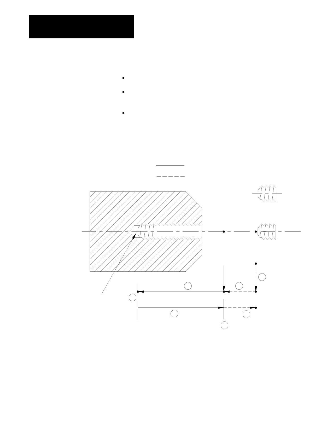
Figure 26.9
G84.1: Left-Hand Tapping Cycle
Cutting feed
Rapid feed
R point level
Initial point
level
1
3
2
Z
Spindle or live tool rotation direction
4
is reversed at hole bottom
R
5
7
6
In the G84.1 left-hand tapping cycle, the control moves the axes in this
manner:
26-18

Chapter 26
Drilling Cycles
CAUTION: The programmer or operator must set the direction
of spindle rotation for tap-in. The control forces the proper
spindle direction for the tap-out, but uses the programmed
spindle direction for the tap-in.
1.
The tool rapids to the initial point level above the hole location.
2.
The threading tool then rapids to the R point level, slows to the
programmed cutting feedrate and begins the tapping operation.
3.
During the tapping operation, the control infeeds the threading tool to
the depth and at the feedrate programmed in the tapping cycle.
4.
If a value was programmed for the P parameter, the threading tool
dwells after it reaches the bottom of the hole, and after the spindle has
been commanded to reverse.
The spindle or live tool reverses to the clockwise direction.
5.
The threading tool retracts at the cutting feedrate to the R point.
6.
If a value was programmed for the P parameter, the threading tool
dwells after it reaches the R point. Dwells may be ignored if the
system installer has chosen to do so in AMP.
The spindle or live tool direction is reversed to counterclockwise.
7.
With G98 active, the cutting tool then accelerates to the rapid feedrate
and retracts to the initial point level.
When the single block function is active, the control stops axis motion and
awaits “cycle start” after steps 1, 2 and 7.
If the operator activates a feedhold during steps 3, 4 or 5, axis motion
stops after step 7. Axis motion also stops during steps 1, 2 and 7.
However, if feedhold is activated during step 7, axis motion stops
immediately.
Important: Your system installer can enable a tap retract feature for this
cycle through PAL. Tap retract enables you to retract the tapping tool and
resume the cycle, or completely abort the tapping operation. Refer to your
system installers documentation for details.
26-19
Chapter 26
Drilling Cycles
(G84.2): Right-Hand
Use this cycle to cut right-handed threads.
Solid-Tapping Cycle
The format for the G84.2 cycle is:
G84.2X__Z__R__F__L__Q__D__S__;
Where :
Is :
X
specifies location of the hole.
Z
defines the hole bottom.
R
defines the R point level.
F
defines the thread lead along the drilling axis (Z in this manual). It is mandatory
and modal in any subsequent solid tapping cycle blocks until a new F-word is
programmed.
The control interprets the F-word as the thread lead in inches per revolution or
millimeters per revolution, depending on the inch/metric mode active.
L
defines the number of times the drilling cycle is repeated.
Q
defines the angle at which to orient the spindle before starting the tap. It is modal
in any subsequent solid tapping blocks until a new Q-word is programmed or the
tapping cycle is cancelled by a G80. To retap a hole, a Q-word must have been
programmed when the hole was originally tapped.
D
defines the return spindle speed, but cannot exceed the maximum tapping
spindle speed set in AMP. This will adjust your Z-axis feedrate according to the
thread lead defined in F.
S
defines spindle speed in rpm.
See section 27.3 for a detailed description of these parameters.
Important: When programming and executing a G84.2 solid-tapping
cycle, remember:
the feedrate of the tapping phases is derived as
(spindle {RPM}* F-lead {IPR}) = IPM
the spindle speed that is active at the start of the cycle determines the
effective Z feedrate
the direction of spindle rotation for tap-in and tap-out phases will be
automatically generated by the control
spindle speed override has no effect on the solid-tapping cycle; you can
use feedrate override to adjust the tapping operation
D cannot exceed the maximum tapping spindle speed set in AMP
you cannot select tools via D-word while in solid-tapping mode
gear changes are locked out
26-20
Chapter 26
Drilling Cycles
on a dual-process lathe, both processes can be in solid-tapping mode at
the same time assuming that they have separate controlling spindles
you must disable CSS before performing solid tapping; an attempt to
execute the tap phase of a solid-tapping cycle with CSS results in a
decode error
cycle stop and feedrate override are acknowledged throughout the cycle,
but can be disabled by G63
you can use active reset to abort the cycle after the cycle stop request
has been acknowledged
to retap a hole, a Q-word must have been programmed when the hole
was originally tapped
block retrace is possible during the tap-in portion of the cycle, but not
during the tap-out
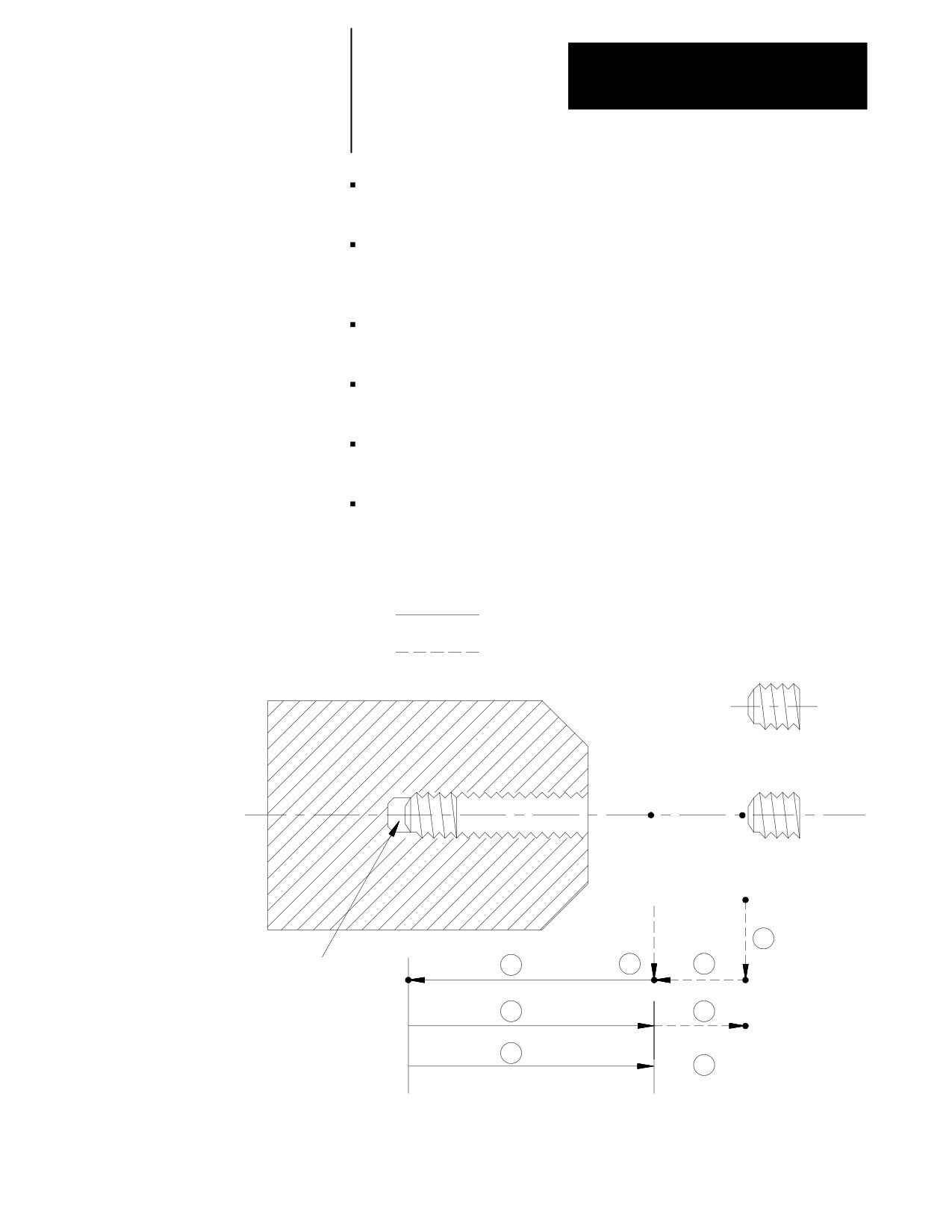
Figure 27.L1
G84.2: Right-Hand Solid-Tapping Cycle
Tapping move
Rapid move
R point level
Initial point level (I)
R
1
Z
Spindle or live tool
rotation direction is reversed
4
3
2
at hole bottom
5
6
G98
5
G99
6
26-21
Chapter 26
Drilling Cycles
In the G84.2 right-hand solid-tapping cycle, the control moves the axes in
this manner:
1.
The tool rapids to the tapping position above the hole location.
2.
The threading tool then rapids to the R point.
3.
The control either orients or stops the spindle.
If a Q-word was programmed:
the control:
yes
orients the spindle
no
stops the spindle
4.
Tap-in: The clockwise rotation of the spindle ramps up to the
programmed S spindle speed and linear motion of the Z axis moves
synchronously to reach the Z position.
5.
Tap-out: The spindle and linear motion reverse to the
counterclockwise direction and retract to the R point.
The tap-out speed is determined by F* S unless you programmed D
(tap-out rpm), in which case tap-out speed is F* D.
At the R point, spindle rotation has ramped to zero.
6.
With G98 active, the cutting tool then accelerates to the rapid feedrate
and retracts to the initial point level.
With G99 active, the cutting tool remains at R point; no movement
occurs.
In single-block mode, the control stops axis motion after phases 1, 2, 3,
and 6 of the cycle (Figure 27.L1).
26-22
Chapter 26
Drilling Cycles
(G84.3): Left-Hand
Use this cycle to cut left-handed threads.
Solid-Tapping Cycle
The format for the G84.3 cycle is:
G84.3X__Z__R__F__L__Q__D__S__;
Where :
Is :
X
specifies location of the hole.
Z
defines the hole bottom.
R
defines the R point level.
F
defines the thread lead along the drilling axis (Z in this manual). It is mandatory
and modal in any subsequent solid tapping cycle blocks until a new F-word is
programmed.
The control interprets the F-word as the thread lead in inches per revolution or
millimeters per revolution, depending on the inch/metric mode active.
L
defines the number of times the drilling cycle is repeated.
Q
defines the angle at which to orient the spindle before starting the tap. It is modal
in any subsequent solid tapping blocks until a new Q-word is programmed or the
tapping cycle is cancelled by a G80. To retap a hole, a Q-word must have been
programmed when the hole was originally tapped.
D
defines the return spindle speed, but cannot exceed the maximum tapping
spindle speed set in AMP. This will adjust your Z-axis feedrate according to the
thread lead defined in F.
S
defines spindle speed in rpm.
See section 27.3 for a detailed description of these parameters.
Important: When programming and executing a G84.3 solid-tapping
cycle, remember:
the feedrate of the tapping phases is derived as
(spindle {RPM}* F-lead {IPR}) = IPM
the spindle speed that is active at the start of the cycle determines the
effective Z feedrate
the direction of spindle rotation for tap-in and tap-out phases will be
automatically generated by the control
spindle speed override has no effect on the solid-tapping cycle; you can
use feedrate override to adjust the tapping operation
D cannot exceed the maximum tapping spindle speed set in AMP
you cannot select tools via D-word while in solid-tapping mode
gear changes are locked out
26-23
Chapter 26
Drilling Cycles
on a dual-process lathe, both processes can be in solid-tapping mode at
the same time assuming that they have separate controlling spindles
you must disable CSS before performing solid tapping; an attempt to
execute the tap phase of a solid-tapping cycle with CSS results in a
decode error
cycle stop and feedrate override are acknowledged throughout the cycle,
but can be disabled by G63
you can use active reset to abort the cycle after the cycle stop request
has been acknowledged
to retap a hole, a Q-word must have been programmed when the hole
was originally tapped
block retrace is possible during the tap-in portion of the cycle, but not
during the tap-out
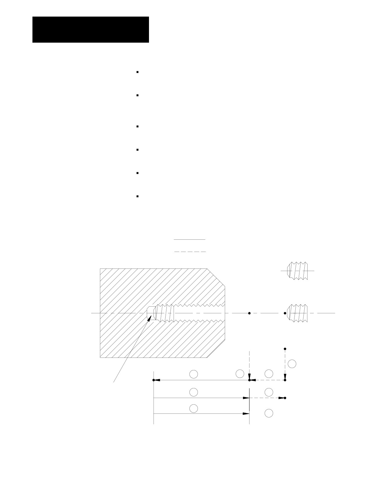
Figure 27.L2
G84.3: Left-Hand Solid-Tapping Cycle
Tapping move
Rapid move
R point level
Initial point level (I)
R
1
Z
4
3
2
Spindle or live tool rotation direction
is reversed at hole bottom
5
6
G98
5
G99
6
26-24
Chapter 26
Drilling Cycles
In the G84.3 left-hand solid-tapping cycle, the control moves the axes in
this manner:
1.
The tool rapids to the tapping position above the hole location.
2.
The threading tool then rapids to the R point.
3.
The control either orients or stops the spindle.
If a Q-word was programmed:
the control:
yes
orients the spindle
no
stops the spindle
4.
Tap-in: The counterclockwise rotation of the spindle ramps up to the
programmed S spindle speed and linear motion of the Z axis moves
synchronously to reach the Z position.
5.
Tap-out: The spindle and linear motion reverse to the clockwise
direction and retract to the R point.
The tap-out speed is determined by F* S unless you programmed D
(tap-out rpm), in which case tap-out speed is F* D.
At the R point, spindle rotation has ramped to zero.
6.
With G98 active, the cutting tool then accelerates to the rapid feedrate
and retracts to the initial point level.
With G99 active, the cutting tool remains at R point; no movement
occurs.
In single-block mode, the control stops axis motion after phases 1, 2, 3,
and 6 of the cycle (Figure 27.L2).
(G85): Boring Cycle, No
The format for the G85 cycle is:
Dwell/Feed Out
G85X__Z__R__F__L__;
Where :
Is :
X
specifies location of the hole.
Z
defines the hole bottom.
R
defines the R point level.
F
defines the cutting feedrate.
L
defines the number of times the drilling cycle is repeated.
26-25
Chapter 26
Drilling Cycles
See page 26-7 for a detailed description of these parameters.
Important: The programmer or operator must start spindle or live tool
rotation.
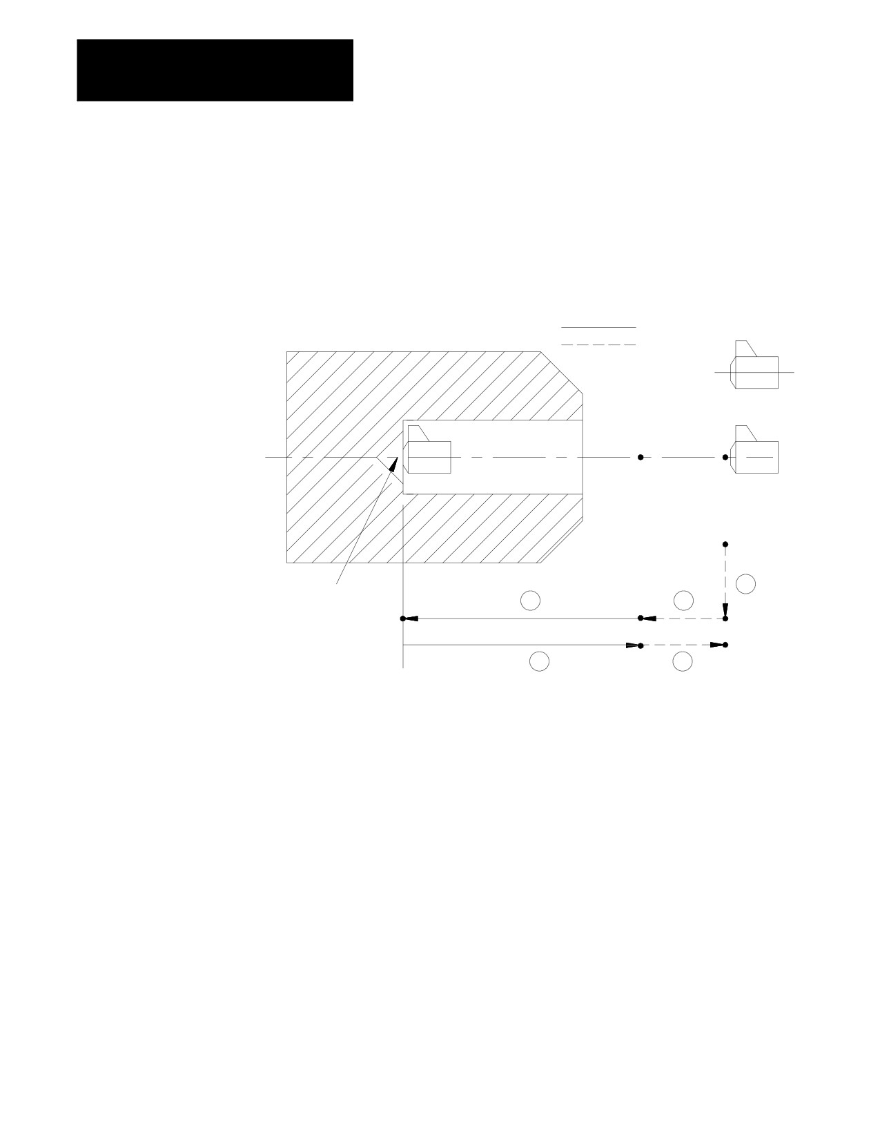
Figure 26.10
G85: Boring Cycle (Without Dwell, Feed Out)
Cutting feed
Rapid feed
R point level
Initial point
level
Hole bottom
1
3
2
4
5
In the G85 boring cycle, the control moves the axis in this manner:
1.
The tool rapids at the initial point level, to the hole location.
2.
The boring tool then rapids to the R point level, slows to the
programmed cutting feedrate and begins the boring operation.
3.
The boring tool continues to drill at the programmed feedrate until it
reaches the depth of the hole as programmed with the Z-word.
4.
The control retracts the boring tool at the cutting feedrate to the R
point.
5.
The control retracts the drilling tool at a rapid feedrate to the initial
point level, as determined by G98.
When the single block function is active, the control stops axis motion
after steps 1, 2 and 5.
26-26
Chapter 26
Drilling Cycles
(G86): Boring Cycle,
The format for the G86 cycle is:
Spindle Stop/Rapid Out
G86X__Z__R__P__F__L__;
Where :
Is :
X
specifies location of the hole.
Z
defines the hole bottom.
R
defines the R point level.
P
defines the dwell period at hole bottom.
F
defines the cutting feedrate.
L
defines the number of times the drilling cycle is repeated.
See page 26-7 for a detailed description of these parameters.
Important: The programmer or operator must start spindle or live tool
rotation.
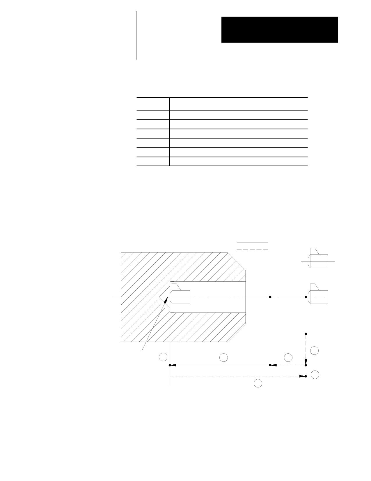
Figure 26.11
G86: Boring Cycle, Spindle Stop/Rapid Out
Cutting feed
Rapid feed
R point level
Initial point
level
Hole bottom
1
4
3
2
Spindle or live tool stops
at hole bottom
6
5
26-27
Chapter 26
Drilling Cycles
In the G86 drilling cycle, the control moves the axis in this manner:
1.
The tool rapids to the initial point level above the hole location.
2.
The cutting tool then rapids to the R point level, slows to the
programmed cutting feedrate and begins the boring operation.
3.
The cutting tool bores at the programmed feedrate until it reaches the
depth of the hole as programmed with the Z-word.
4.
If the user has entered a value for the P parameter, the cutting tool
dwells after it reaches the bottom of the hole.
5.
The spindle or live tool stops rotating.
6.
The boring tool is then retracted at a rapid feedrate to the initial point
level, as determined by G98. Spindle or live tool rotation continues
forward.
When the single block function is active, the control stops axis motion
after steps 1, 2 and 6.
(G86.1): Boring Cycle, Tool
The format for the G86.1 cycle is:
Shift
G86.1X__Z__ I__K__ R__F__L__;
Q__
Where :
Is :
X
specifies location of the hole.
Z
defines the hole bottom.
Q or I, K
defines the tool shift amount.
R
defines the R point level.
F
defines the cutting feedrate.
L
defines the number of times the drilling cycle is repeated.
See page 26-7 for a detailed description of these parameters.
Important: The programmer or operator must start spindle or live tool
rotation.
26-28
Chapter 26
Drilling Cycles
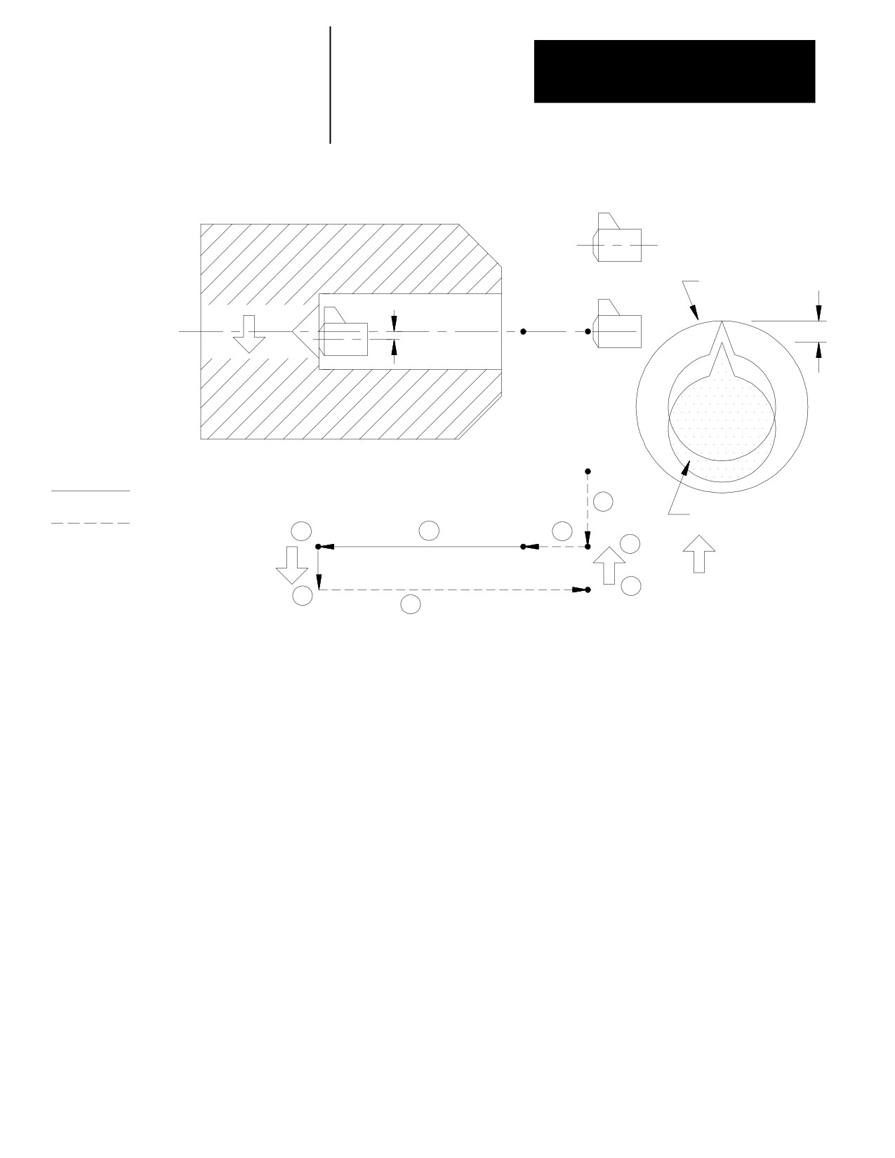
Figure 26.12
G86.1: Boring Cycle, Tool Shift
Hole bottom
Bored hole
R point level
Shift
Q
Spindle orient after
dwell at Z point level
to position tool for
removal
Initial point
level
Cutting feed
1
Spindle or live tool oriented
Rapid feed
and tool shifted
4
3
2
8
Shift
Shift
Q
7
5
6
In the G86.1 boring cycle, the control moves the axes in this manner:
1.
The tool rapids to the initial point level above the hole location.
2.
The boring tool then rapids to the R point level, slows to the
programmed cutting feedrate, and begins the boring operation.
3.
The boring tool bores at the programmed feedrate to the
pre-programmed depth of the hole (defined by the Z-word in the
boring cycle block).
4.
The control positions the spindle or live tool at the bottom of the hole
in a particular orientation, determined by the system installer in AMP.
5.
To prevent the boring tool from damaging the sides of the bored hole
during retraction, the boring tool is shifted in either of two methods
which are explained below and illustrated in Figure 26.12.
26-29
Chapter 26
Drilling Cycles
The shift direction is determined by two possible methods:
Method I
This shift method is a single-axis shift. The direction and axis for the shift
is set in AMP by your system installer or can be altered using the drilling
cycle parameter table. See page 26-38.
the direction of the axis is specified as + or -.
the feedrate using this shift method is always rapid traverse.
the Q-word shift amount is always interpreted as a positive value; a
negative Q-word is not allowed.
Method II
The direction of the shift using this method is programmed in the boring
cycle block. Program a shift amount for axes in the current plane (G17,
G18, or G19) by using only these words:
I__ programs an X axis move.
K__ programs a Z axis move.
Follow the I- and K-words (modal during drilling cycles) with incremental
values in the block that programs the hole position.
When using Method II, remember:
if both axes in the current plane are to be shifted, specify both words to
move the axes
the generated move is a single linear move and executes at rapid
traverse
6.
The boring tool is then retracted at a rapid feedrate to the initial point
level as determined by G98.
7.
After reaching initial point level, the control again positions the
spindle or live tool at the bottom of the hole in a particular orientation
as determined by the system installer in AMP.
8.
After reaching the initial point level, the boring tool is shifted back
(in a manner previously explained and illustrated) and the spindle or
live tool is re-started in the counterclockwise direction.
When the single block function is active, the control stops axis motion
after steps 1, 2, 4, and 8.
26-30
Chapter 26
Drilling Cycles
When using Method II, remember:
the generated move is a single linear move and executes at
(G87): Back Boring Cycle
The format for the G87 back boring cycle is:
G87X__Z__ I__J__K__ R__F__L__;
Q__
Where :
Is :
X
specifies location of the hole.
Z
defines the Z point level. The Z point level in this case is the top of the
hole that is being cut by the back boring operation.
Q or I,
defines the tool shift amount.
J, K
R
defines the position beyond the hole bottom so the tool can safely shift.
F
defines the cutting feedrate.
L
defines the number of times the drilling cycle is repeated.
Important: This cycle requires an existing hole through which the back
boring tool can be safely lowered prior to the back boring operation.
26-31
Chapter 26
Drilling Cycles
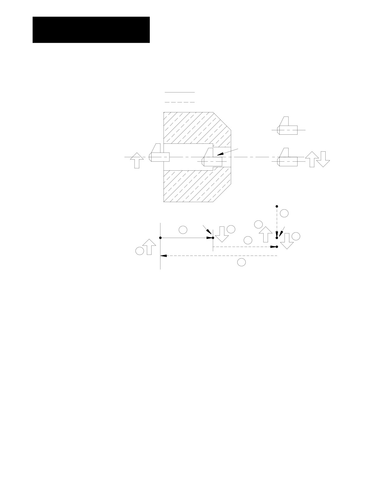
Figure 26.13
G87: Back Boring Cycle
Cutting feed
Rapid feed
Hole bottom
Z point level
Initial point
level
1
Spindle or live tool
Spindle or live tool
orientation
Spindle or live tool
8
orientation
rotation forward
5
6
2
7
4
3
In the G87 back boring cycle, the control moves the axes in this manner:
1.
The tool rapids to the initial point level above the hole location.
2.
After the back boring tool is positioned, the control orients the tool to
a position determined in AMP by the system installer.
The control shifts the boring tool by one of two possible methods as
described on page 26-33. The shift method is determined in AMP by
the system installer. Refer to the documentation supplied by your
system installer for additional information.
26-32
Chapter 26
Drilling Cycles
Method I
This shift method is a single axis shift. The direction and axis for the
shift is set in AMP by the system installer or can be altered using the
drilling cycle parameter table. See page 26-38.
the direction of the axis is specified as + or -
the feedrate using this shift method is the programmed feedrate
the Q-word shift amount is always interpreted as a positive value;
a negative Q-word is not allowed
Method II
The direction of the shift using this method is programmed in the
boring cycle block. Program a shift amount for axes in the current
plane only (G17, G18, G19) by using these words:
I__ programs an X axis move.
K__ programs a Z axis move.
Follow the I- and K-words (modal during drilling cycles) with
incremental values in the block that programs the hole position.
When using Method II, remember:
When using Method II, remember:
if both axes in the current plane are to be shifted, specify both
words to move the axes
the move generated is a single linear move and is executed at rapid
traverse
3.
The back boring tool moves at a rapid feedrate through the existing
hole to the depth designated by the R-word.
4.
Once the designated depth is reached, the back boring tool shifts the
same distance but in the opposite direction as the previous shift (the
shift made in step 2).
After this shift, the programmer or operator must start the spindle or
live tool. The spindle or live tool must rotate in the clockwise
direction.
5.
The control retracts the back boring tool at the cutting feedrate to a
level specified by the Z-word.
26-33
Chapter 26
Drilling Cycles
6.
After reaching the Z depth, the spindle or live tool rotation stops so
that the control can re-orient the back boring tool to the position
specified in AMP.
The back boring tool is shifted a third time, in the same manner as in
step 2, so that it is again “off-center” and can be removed through the
existing hole.
7.
The back boring tool moves at a rapid feedrate to the initial point
level regardless of whether G98 or G99 is active.
8.
The back boring tool is shifted a fourth time, in the same manner as
in step 2, returning to the initial X coordinates of the hole location.
(G88): Boring Cycle,
The format for the G88 cycle is:
Spindle Stop/Manual Out
G88X__Z__R__P__F__L__;
Where :
Is :
X
specifies location of the hole.
Z
defines the hole bottom.
R
defines the R point level.
P
defines the dwell period at the hole bottom.
F
defines the cutting feedrate.
L
defines the number of times the drilling cycle is repeated.
See page 26-7 for a detailed description of these parameters.
Important: The programmer or operator must start spindle or live tool
rotation.
26-34