9/Series CNC Lathe. Operation and Programming Manual - page 21
Chapter
25
Thread Cutting
25.0
The 9/Series control provides two methods of thread cutting:
Chapter Overview
Single-pass thread cutting
G33 and G34 blocks generate a single thread cutting pass. G33 can cut
straight, tapered, face, multistart, and multiblock threads. G34 can cut
thread passes of increasing or decreasing leads.
Automatic thread-cutting cycles
G21 and G78 provide for fully automatic thread cutting with multiple
passes at a programmed depth, including springing pass and clean-up
pass options.
This chapter describes the following topics that relate to thread cutting:
Topic:
On page:
Considerations for thread cutting
25-2
Chamfering your threads
25-4
Single pass threading mode
25-6
Single pass variable lead thread cutting
25-12
Single pass threading cycle
25-16
O.D. & I.D. multipass threading routine
25-20
If you are using a dual-processing system, you may need to use slightly
different threading methods. Refer to page 30-15 for details.
Important: Descriptions in this chapter are written assuming the control is
in the G18 plane and that plane has been defined as the ZX plane. If your
system has a different plane active, operation of these features is different.
Parameters are defined here assuming Z is the first axis in the plane, and X
is the second axis in the plane. If, for example, the XZ plane is the
currently active plane, descriptions in this document should be interpreted
accordingly (i.e., Z axis description applies for X axis and X axis
description applies to Z axis. See your system installer’s documentation
for details on the plane definitions on your system.
25-1
Chapter 25
Thread Cutting
25.1
When performing threading operations, remember:
Considerations for Thread
Emergency Stop - Pressing the emergency stop during threading causes
Cutting
all axes to come to a rapid stop. This likely causes damage to the part or
tool and resuming the threading moves is not possible.
<CYCLE STOP> (cycle suspend) - A cycle stop does not occur if this
button is pressed during a threading pass; instead the block executes in
this manner:
If G33, or G34 threading is being executed then axis motion continues
and cycle stop is ignored.
If G78 or G21 threading is being executed, one of two possible paths is
taken by the control. If the threading retract feature has been enabled,
the control immediately chamfers out of the thread, retracts the tool and
then returns to the start point of the threading cycle. If no threading
retract is enabled then the control continues execution until it has
completed the entire pass of the threading cycle and returned to the start
point of the move.
Overrides - During the execution of any threading pass, all feedrate
overrides are fixed at 100%.
Single Block - In single block mode the entire cycle is executed for
G21. For G78 one complete sub-cycle (including the return move to the
initial point) is performed each time cycle start is pressed. When
performing single pass threading (G33 or G34) motion stops at the end
of the threading block typically resulting in a ringing of the thread.
Dry Run - Whether or not the “dry run” and spindle speed override
functions are operable during threading is determined by the system
installer’s PAL program.
Radius/Diameter Mode - The control performs threading in either
radius or diameter modes. Radius/Diameter mode only affects the
controls interpretation of the X parameter.
Start point - Due to axis acceleration and other machine dynamics, the
threading cycles should be programmed such that the axes have room to
attain speed prior to contacting the workpiece. Failure to do so may
result in the initial thread lead being incorrect.
Controlling spindle - On systems with multiple spindles, the
controlling spindle (selected with G12) is the synchronized spindle used
for thread cutting. The controlling spindle RPM, in conjunction with
the programmed thread lead (F or E), determine the threading axis
feedrate.
25-2
Chapter 25
Thread Cutting
Axis feedrates - When threading, the speed of the cutting axis is
determined by the controlling spindle speed and the thread lead through
this equation:
axis feedrate
= (S) / (F inches per revolution)
= (S) / (E threads per inch)
= (S)(E inches per thread)
Where :
Is :
S
the actual speed of the controlling spindle (programmed spindle speed times
the spindle speed override switch setting in percent)
F
threads per revolution or degree depending on the current active mode
E
threads per inch or inches per revolution as determined in AMP by your
system installer.
The programmer should use this equation to verify that the feedrate
resulting from the thread parameters does not exceed the maximum
allowable feedrate for the cutting axis. Otherwise an error results and
axis motion stops. This equation can also be applied to face threads and
tapered threads.
Pullout angles - During threading cycles, the control synchronizes the
moves of the X and Z axes with the spindle speed. This occasionally
may force the X axis to move quite rapidly in order to produce the
desired thread taper or pullout angles at the rates dictated by the active
spindle speed. Compounded with the fact that many machines have X
axis feedrate limits lower than those for the Z axis, the result may be
velocity limitations. This is best prevented by first executing a Feed
Check prior to actually cutting the threads and then reducing spindle
speed or changing the pullout angle where necessary.
Tapered Thread Lead - When cutting a tapered thread, the thread lead
(E- or F-word) is applied to the axis that travels the greatest distance
from the start to the end of the threading pass.
Infeed - Plunge infeed relies on a sharp tool made at the exact thread
angle that cuts on both sides of the tip as it is fed perpendicular to the
work on successive passes. On larger threads, this type of infeed may
cause vibration. In that case, angular infeed may be preferred. This
results in the tool being fed along the thread flank with each successive
pass, meaning only one side of the tip cuts. Figure 25.1 illustrates
plunge and angular infeed.
25-3

Chapter 25
Thread Cutting
Figure 25.1
Angular versus Plunge Infeed
Angular Infeed
Plunge Infeed
Cutting tool
Cutting tool
The G78 threading pass allows the selection of different infeed types by
programming a P-word. If you use any of the other threading methods,
it is necessary to insert a small Z move to generate an angular feed.
Form Cut Threading - The auto threading cycles (G21 and G78)
assume a sharp triangular tool. If you use a shaped-tip tool, the tool
loading is affected. Specifically, the first cut is loaded slightly less than
successive cuts. Though generally insignificant, if this is a concern, we
suggest that the initial cut depth be compromised as necessary to ensure
that the tool is not overloaded on successive passes.
25.2
Using Thread Chamfer
Chamfering Your Threads
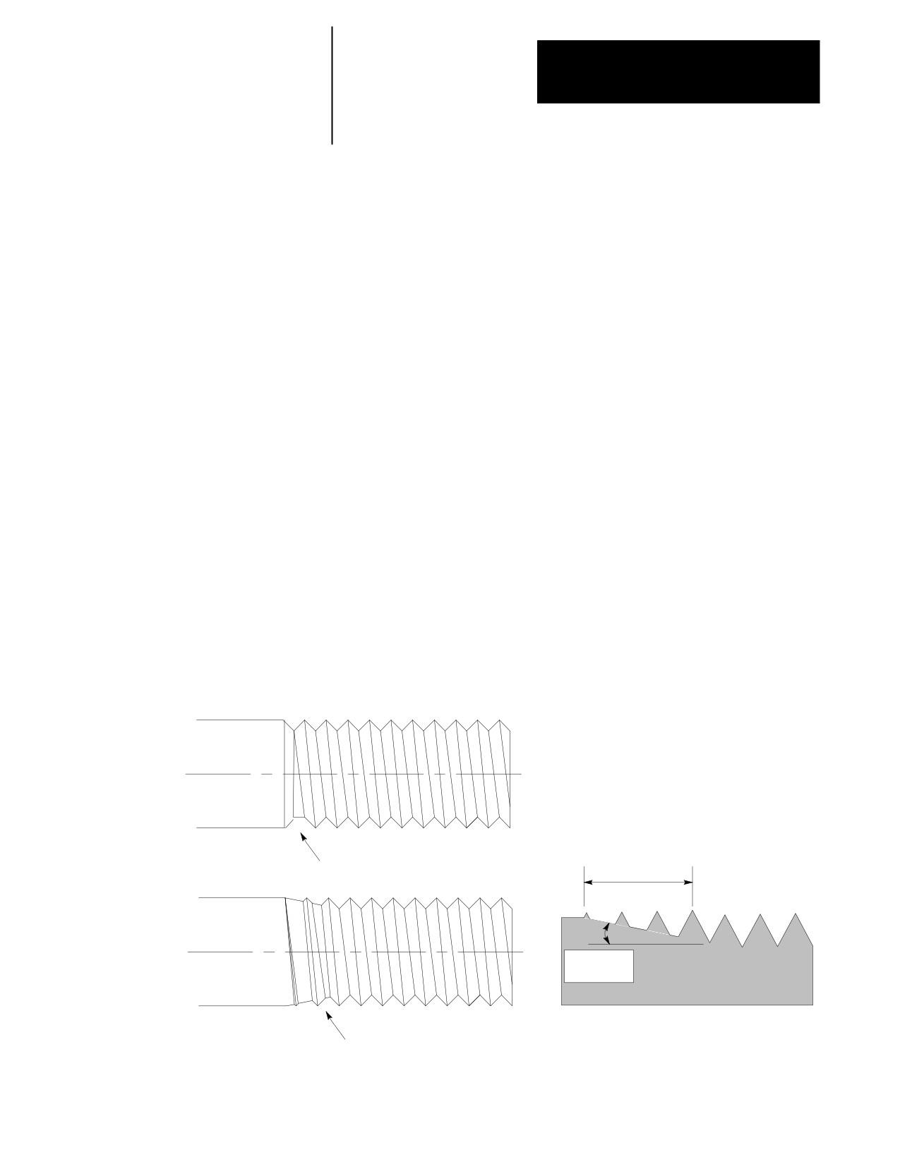
The thread chamfer feature, enabled in PAL, cuts a chamfer at the end of a
thread cutting pass. When the feature is activated, the control
automatically cuts a chamfer at the end of each thread cutting pass to
assure the tool is fully out of the thread before it is retracted.
This feature prevents the “ring” at the end of the thread that typically
occurs when the control stops threading motion to retract the tool. This
ring occurs when the threading axis reaches the endpoint of the thread and
decelerates before executing the retract move. Typically spindle RPM
does not compensate for this deceleration of the threading axis thus
causing a ring at the end of the thread.
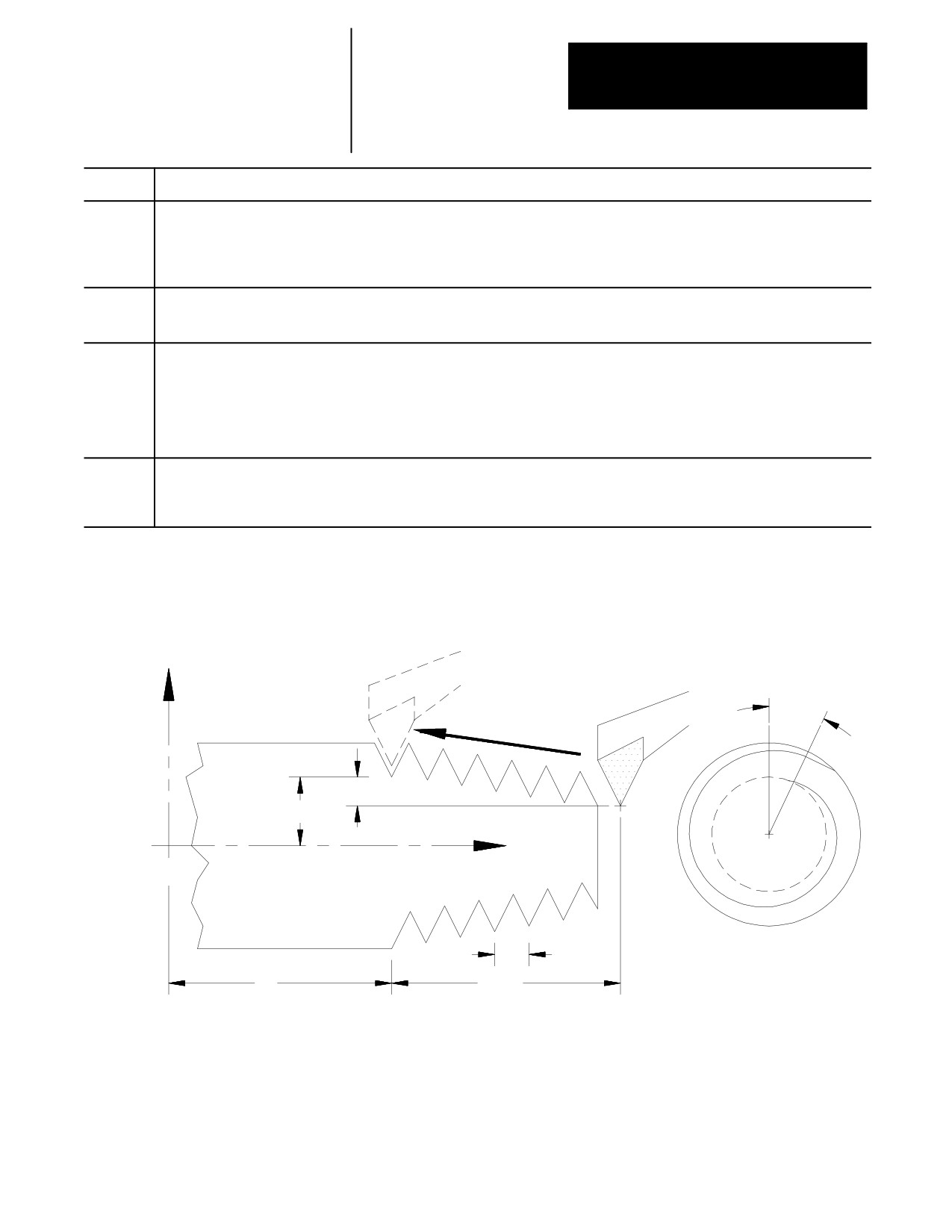
Both the thread retract and thread chamfer use the same values (set in
AMP) for the pullout distance “r” and pullout angle “a” of the chamfer.
“r” is entered as the number of threads to be chamfered, “a” is entered as
the angle of the chamfer in degrees measured from the same axis as the
thread lead.
25-4
Chapter 25
Thread Cutting
Important: This feature may only be used with the G78 or G21 threading
cycle. It is ignored if a G33 or G34 threading pass is being made.
Using Thread Retract
Enabled in PAL, thread retract lets you interrupt a thread cutting operation
without damaging the thread by pressing <CYCLE STOP>. When the
operation is interrupted, the control automatically performs a retract (by
cutting a chamfer) out of the thread to prevent damage to the thread due to
ringing. Once free of the thread the control retracts the tool and returns it
to the start point. Also, program execution stops at this point.
If you attempt to interrupt the thread cutting operation without thread
retract active, the control does not interrupt the operation until the end of
the currently executing threading pass.
Thread Chamfer and Thread Retract Parameters
Both the thread retract and thread chamfer use the same values (set in
AMP) for the pullout distance “r” and pullout angle “a” of the chamfer.
“r” is entered as the number of threads to be chamfered, “a” is entered as
the angle of the chamfer in degrees measured from the same axis as the
thread lead.
Figure 25.2
Ringing occurs when retracting from thread without using thread
chamfer or thread retract.
Number of
threads
Ringing from no chamfer when cutting
for chamfer (r)
tool is retracted out of thread.
Pullout
angle (a)
Smooth exit from thread when cham-
fer is made, no ringing at end of
thread. Root depth slowly decreases.
25-5
Chapter 25
Thread Cutting
25.3
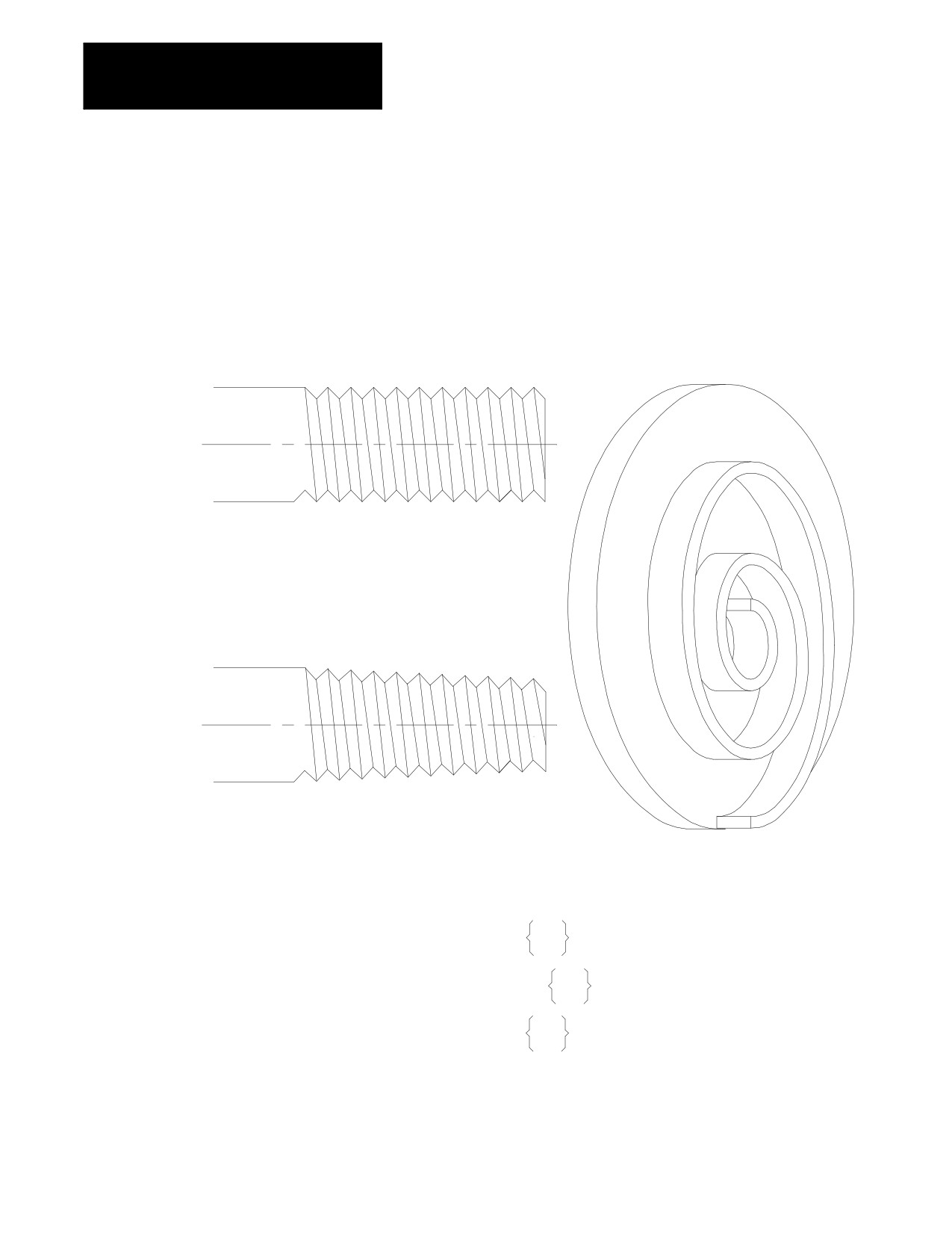
The G33 thread cutting mode can cut straight, tapered, face, and multistart
threads that have constant thread leads (use G34 to cut threads that do not
Single Pass Threading Mode
have a constant lead). The G33 thread cutting mode is a mode, not a cycle
(G33)
and does not generate any extra motion blocks. This mode synchronizes
the thread cutting tool motion with the spindle to allow programming
multiple passes over the same threads.
Figure 25.3
Constant Lead Threads
Parallel thread
Face thread
Tapered thread
The format for the G33 thread cutting operation is:
Parallel thread G33Z__ F__ Q__;
E
Tapered thread
G33X__Z__ F__ Q__;
E
Face thread
G33X__ F__ Q__;
E
25-6
Chapter 25
Thread Cutting
Where :
Is :
X
This parameter is the end point of the thread cutting move in the X axis. This parameter may be an incremental or absolute and radius or
diameter value. If not present there must be a Z parameter. If an X parameter is present, it indicates either a face, tapered, or lead-in
thread. When used in a G33 block without a Z parameter, a facing thread is made parallel to the X-axis at the Z axis position prior to the
G33 block. X values maybe entered as a radius or a diameter value. X may also be programmed as an incremental or absolute value.
The initial minor diameter of any straight or tapered thread is determined by the position of the X axis prior to the G33 block.
Z
This parameter is the end point of the thread cutting move in the Z axis. This parameter may be an incremental or absolute value. If not
present there must be an X parameter. When a Z parameter is used in a G33 block without an X parameter the threading pass is made
parallel to the Z-axis at whatever X position the tool tip was at prior to the G33 block.
E F
This parameter may be entered by using either an E- or F-word. It represents the thread lead along the axis with the largest programmed
distance to travel to make the thread cut. It is mandatory when cutting any threads.
If the E-word is programmed, its value (sign ignored) is equal to the number of threads per inch or inches per thread (determined in AMP)
regardless of whether inch or metric mode is active at the time.
If the F-word is programmed, its value (sign ignored) is the thread lead in inches per revolution or millimeters per revolution, depending on
the mode in which the control is operating.
Q
This optional parameter provides a relative value for the start offset angle of the thread. Its primary use is in cutting multistart threads.
For example, if a threading pass were made with a value of zero here, and then followed by another pass with a value of 180 then the
second cut would be started 180 degrees from the first resulting in a two start thread. If two more passes are then made, one with a
parameter value of 90 and one with a value of 270, the result would be a four-start thread.
Figure 25.4
G33 Block Parameters
X
Q
X Inc.
X Abs.
Z
1/E, E or F
Z
Z
Abs.
Inc.
Important: Do not re-program the G33 command in consecutive threading
blocks. Doing so will cause the control to pause axis motion (possibly
damaging the thread) while the axis re--synchronizes with the spindle.
Consecutive threading blocks in the following example are blocks N3 and
N4, and blocks N8 and N9.
25-7
Chapter 25
Thread Cutting
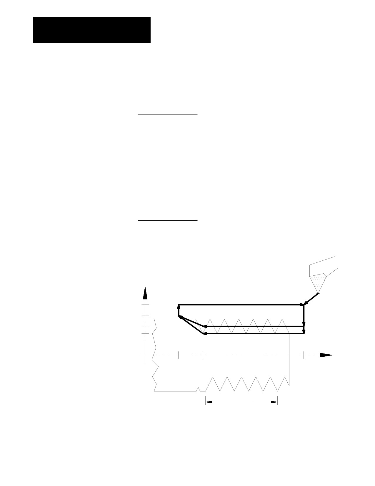
Example 25.1
Parallel Thread Cutting
Thread lead:
5 threads/inch (.20 inch pitch)
Depth of cut:
.7 inch (after final pass)
Number of cutting passes: 2
N1 M03 S50;
N2 G00 X1.5 Z2.2;
N3 X.9;
N4 G33 Z.8 F.2;
N5 Z.5 X1.2
N6 G00 X1.5;
N7 Z2.2;
N8 X.7;
N9 G33 Z.8 F.2;
N10 Z.5 X1.2
N11 G00 X1.5;
N12 Z2.2;
Figure 25.5
Parallel Thread Cutting Results from Example 25.1
X
N7
N12
N2
1.5
N11
N6
N3
1.2
N5
N4
0.9
N10
N8
0.7
N9
Z
0.5
0.8
2.2
1.0
If both E and F are programmed in the same block the right-most
parameter takes effect for that block.
25-8
Chapter 25
Thread Cutting
The programmed lead remains in effect until another thread lead value is
programmed, the control is reset, or an M02 or M30 end of program block
is executed.
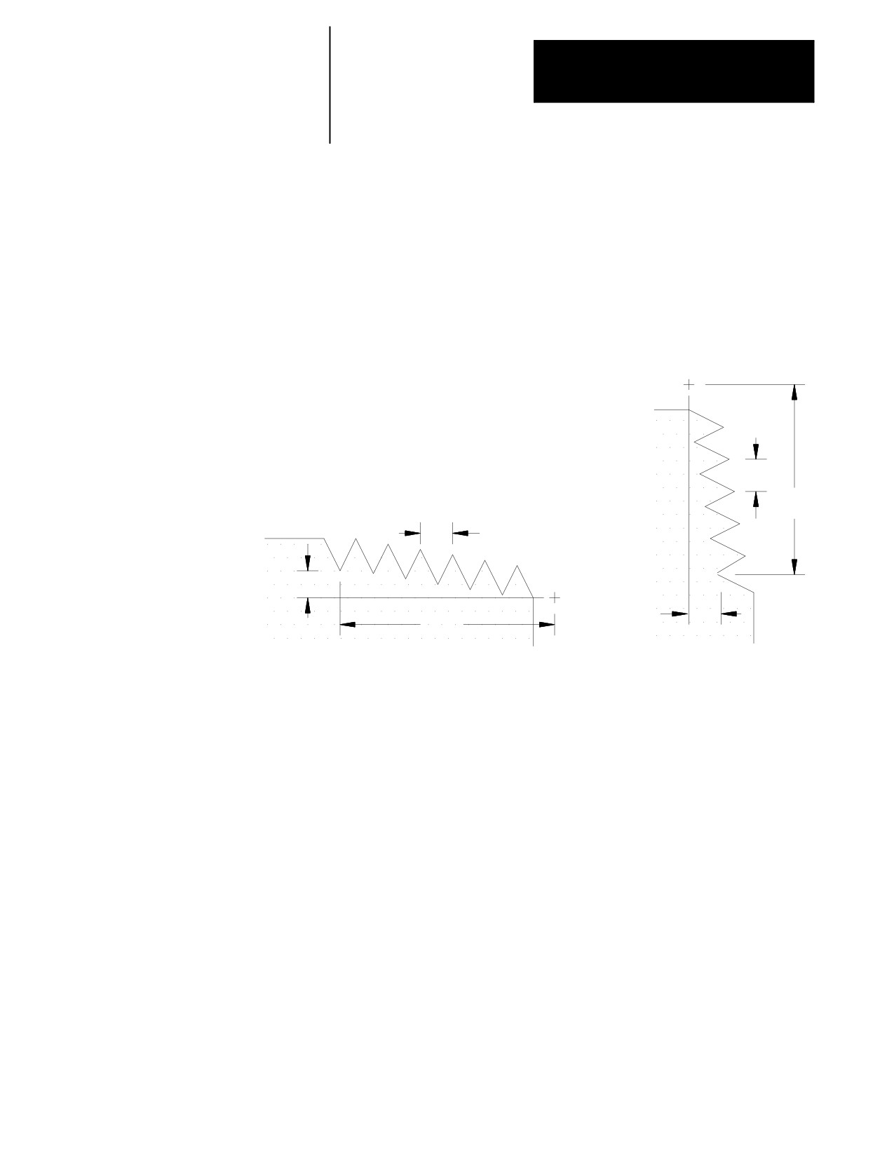
For tapered threads, the thread lead (determined by the F- or E-word) is
applied along the axis that travels the greatest distance when cutting the
thread. See Figure 25.6.
Figure 25.6
Lead Designation for Tapered Thread
If Z < X then thread lead is along X
1/E, E or F
If Z ³ X then thread lead is along Z
X
1/E, E or F
X
Z
Z
When the X-axis is used as the thread lead axis for E or F, program thread
leads as radial values.
25-9
Chapter 25
Thread Cutting
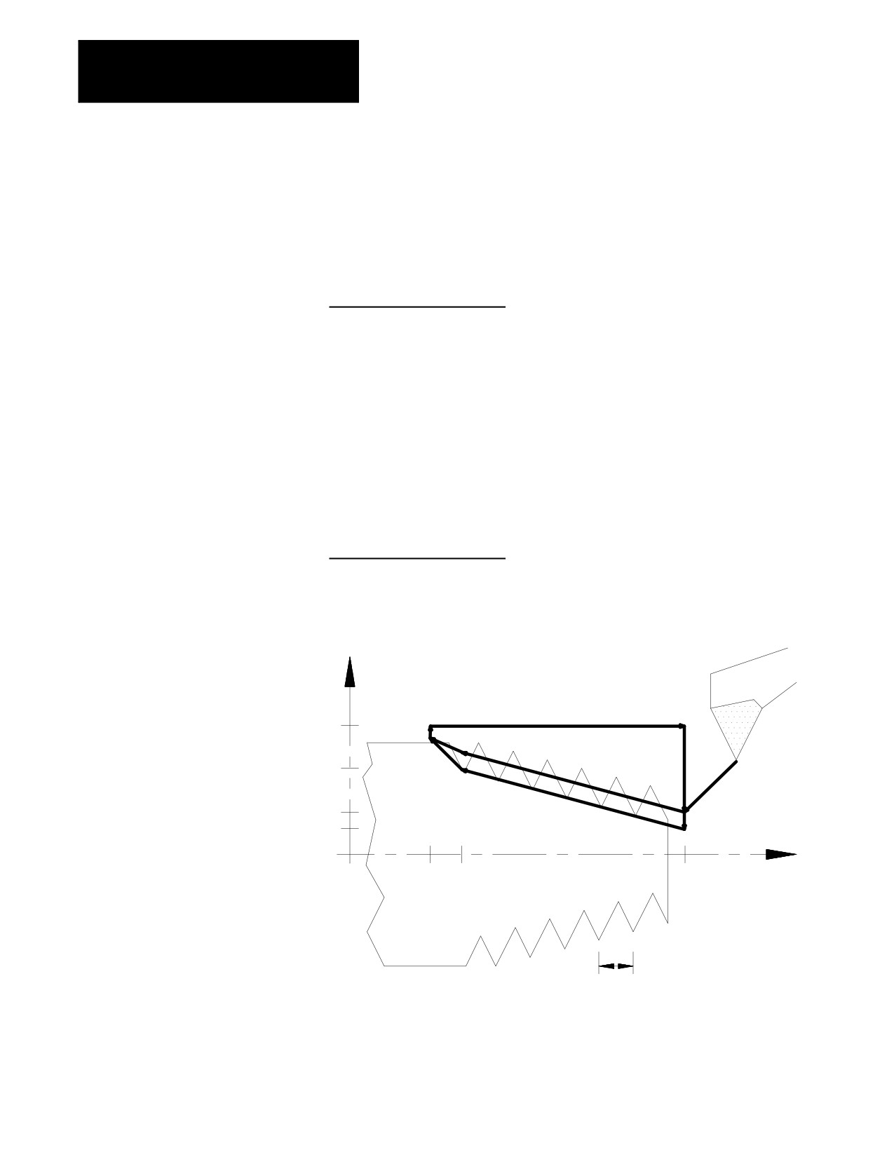
Example 25.2
Tapered Thread Cutting
Thread lead: .125 threads/mm (8 mm pitch)
Depth of cut: 1 mm (X direction)
Number of cutting passes: 2
N1 M03 S30;
N2 G77 G00 X20. Z4.;
N3 G33 X48. Z-47. F8;
N4 X52 Z-55;
N5 G00 X60.;
N6 Z4.;
N7 X12.;
(second pass)
N8 G33 X40. Z-47.;
N9 X52 Z-55;
N10 G00 X60.;
N11 Z4.;
Figure 25.7
Results of Tapered Thread Cutting Example 25.2
N6
N11
60
N4
N9
40
N3
N7
N8
N2
20
12
Z
-70
-55
-47
4
8mm
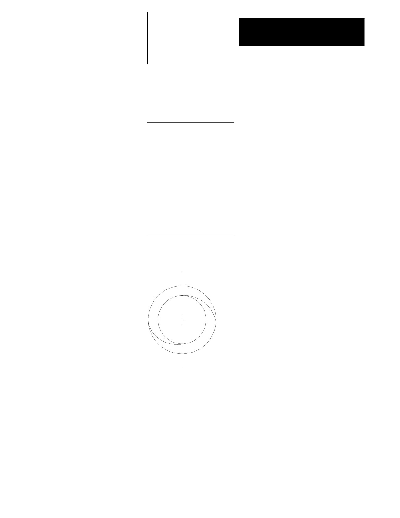
Multiple-thread cutting can be programmed by assigning a thread cutting
start shift angle using a Q-word. Omission of a Q-word indicates a shift
angle of 0 (synchronizes at the spindle marker). Entering a Q word will
offset the axis synchronization from the spindle marker position.
25-10
Chapter 25
Thread Cutting
Example 25.3
Multistart Thread Cutting
Thread lead:
2 threads/inch (.50 inch pitch)
Depth of cut:
.7 inch (after final pass)
Number of cutting passes: 2 at 180 degrees apart
N1 M03 S50;
N2 G00 X1.5 Z2.2;
N3 X.9;
N4 G33 Z.8 E2. Q0;
N5 Z.5 X1.2
N6 G00 X1.5;
N7 Z2.2;
N8 X.9;
N9 G33 Z.8 E2. Q180;
N10 Z.5 X1.2
N11 G00 X1.5;
N12 Z2.2;
Figure 25.8
Multistart Thread Cutting Results from Example 25.3
End View
180°shift angle between thread starts
25-11
Chapter 25
Thread Cutting
25.4
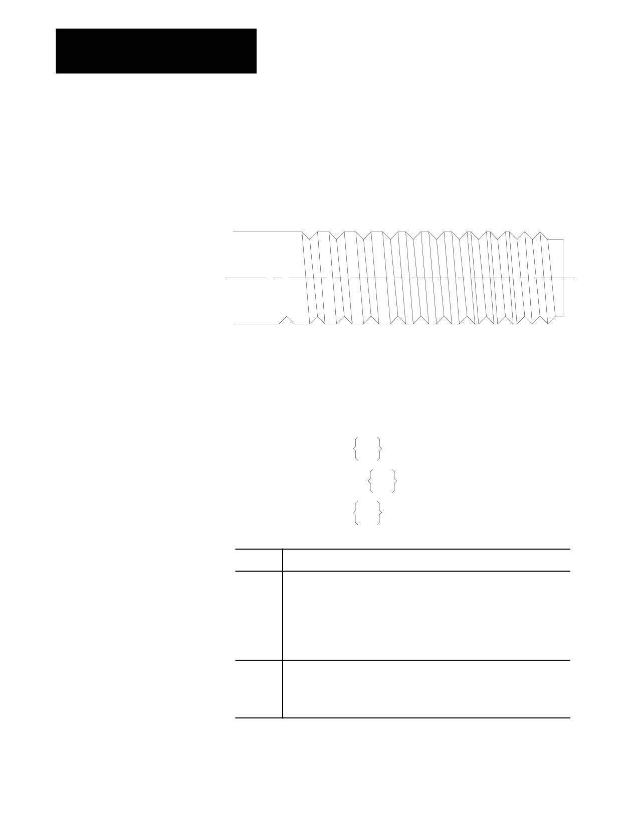
The G34 code programs the variable lead thread cutting mode. It is
programmed almost identically to the G33 thread cutting mode with the
Single Pass Variable Lead
addition of a K-word used to program the amount of lead variation per
Thread Cutting (G34)
revolution.
Figure 25.9
Variable Lead Thread
Important: Do not re-program the G34 command in consecutive threading
blocks. Doing so will cause the control to pause axis motion (possibly
damaging the thread) while the axis re--synchronizes with the spindle.
The format for the G34 threading mode is:
Parallel thread G34Z__ F__ Q__K__;
E
Tapered thread
G34X__Z__ F__ Q__K__;
E
Face thread
G34X__ F__ Q__K__;
E
Where :
Is :
X
This parameter is the end-point of the thread cutting move in the X axis. This
parameter may be an incremental or absolute and radius or diameter value. If
not present, there must be a Z parameter. If an X parameter is present, it
indicates either a face, tapered, or lead-in thread. When used in a G34 block
without a Z parameter, a facing thread is made parallel to the X-axis at the Z axis
position prior to the G34 block.
The initial minor diameter of any straight or tapered thread is determined by the
position of the X axis prior to the G34 block.
Z
This parameter is the end-point of the thread cutting move in the Z axis. This
parameter may be an incremental or absolute value. If not present, there must
be an X parameter. When a Z parameter is used in a G34 block without an X
parameter, the threading pass is made parallel to the Z-axis at whatever X
position the tool tip was at prior to the G34 block.
25-12
Chapter 25
Thread Cutting
Where :
Is :
E F
This parameter may be entered by using either an E- or F-word. It represents the
thread lead along the axis with the largest programmed distance to travel to
make the thread cut. It is mandatory when cutting any threads.
If the E-word is programmed, its value (sign ignored) is equal to the number of
threads per inch or inches per thread (determined in AMP) regardless of whether
inch or metric mode is active at the time.
If the F-word is programmed, its value (sign ignored) is the thread lead in inches
per revolution or millimeters per revolution, depending on the mode in which the
control is operating.
In a G34 block, E or F indicates the initial thread lead used at the start of the
threading pass.
Q
This optional parameter provides a relative value for the start offset angle of the
thread. Its primary use is in cutting multistart threads. For example, if a
threading pass were made with a value of zero here, and then followed by
another pass with a value of 180°,then the second cut would be started 180°
from the first resulting in a two-start thread. If two more passes are then made
(one with an a parameter value of 90°and one with a value of 270°), the result
would be a four-start thread.
K
Program the difference in the thread lead per spindle revolution (inch/rev/rev or
mm/rev/rev). The amount of K is added to the thread lead (E or F) after each
thread is cut. K may be programmed as a positive (increasing thread lead) or a
negative (decreasing thread lead) value.
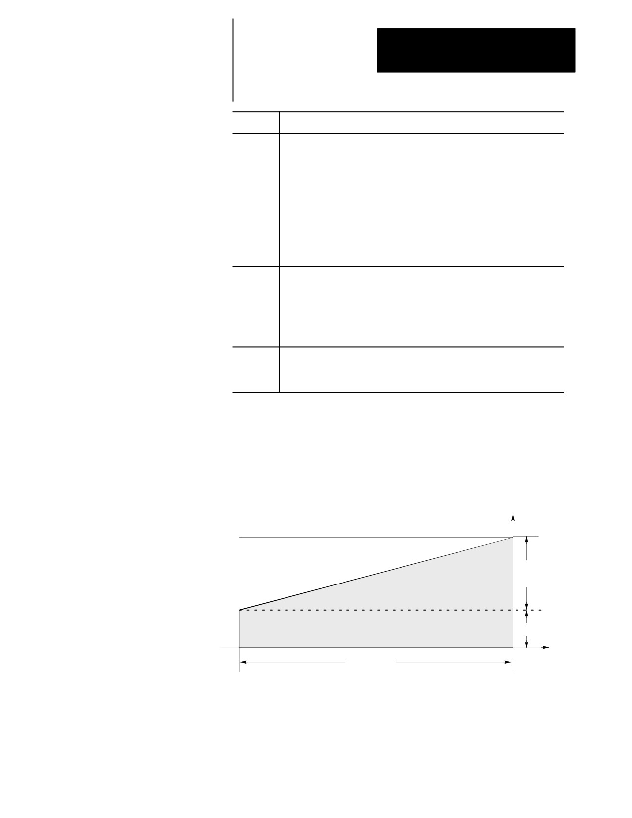
The lead changes continuously during the move. At any point during the
move, you can calculate the lead with this formula:
instantaneous lead = F + (K * number of revs since the start)
Figure 25.10
Instantaneous Lead
Lead
K * Revs
Distance
F
Revolutions
The actions of the G34 variable lead threading operation are identical to
the G33 threading operation with the exception of the variable thread lead.
See the G33 threading section for details and examples of single-pass
threading blocks that cut parallel, tapered, or face threads.
25-13
Chapter 25
Thread Cutting
Metric and inch Lead variation limits are indicated below:
+/- 0.0001
to
+/- 100.0000 mm/rev
+/- 0.000001 to
+/- 1.000000 inch/rev
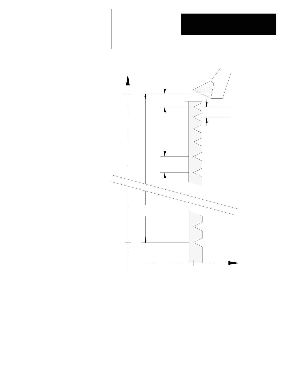
Example 25.4
Variable Lead Face Threading Using G34
N1G00G07X57.Z37.5F100;
N2G91;
N3G34X-47.5F.1K.071;
N4G00Z10.;
N5X47.5;
25-14
Chapter 25
Thread Cutting
Figure 25.11
Results of Variable Lead Face Threading Example
X
57.0
.1 mm/rev
.171 mm/rev
Z
.526 mm/rev
57.0
37.5
.171 mm/rev
47.5mm
9.5
Z
37.5
25-15
Chapter 25
Thread Cutting
25.5
The G21 single pass threading cycle can be programmed to cut parallel or
tapered fixed lead threads (variable lead threads may only be cut using a
Single Pass Threading Cycle
G34 block). This threading cycle performs a predetermined series of
(G21)
machining steps designated by a single program block.
The two chamfering features (threading retract and threading chamfer)
described on page 25-4 can also be used with this threading cycle. The
parameter to enable these and determine their angle and length is set in
AMP. The thread chamfer feature must also be enabled through PAL.
This threading cycle repeats automatically after every block that contains
axis words until the cycle is cancelled. These axis words generate rapid
moves. A G21 single pass threading cycle is canceled by programming
any other G-code in modal group 1 (this includes G00, G01, etc.).
The conditions to be satisfied to execute this thread cutting cycle are
described on page 25-2, thread cutting considerations.
Before programming the G21 threading cycle, the cutting tool must be
positioned away from the part at a location that allows the control to
execute the cycle correctly.
Straight Thread Cutting
This format is for programming a single pass straight threading cycle:
G21 X__ Z__ {F__};E
Where :
Is :
X
This parameter is the start-point of the thread cutting move in the X axis. This
parameter may be an incremental or absolute and radius or diameter value. This
is the depth that the X axis moves to before starting the thread cutting pass. This
value may be replaced in any block following the G21 block while the G21 cycle
is active. X may also be programmed as an incremental or absolute value.
Z
This parameter is the end-point of the thread cutting pass in the Z axis. This
parameter may be an incremental or absolute value. Z parameters are always
entered as a radius values regardless of the current mode.
E F
This parameter may be entered by using either an E- or F-word. It represents the
thread lead along the axis with the largest programmed distance to travel to
make the thread cut. It is mandatory when cutting any threads.
If the E-word is programmed, its value (sign ignored) is equal to the number of
threads per inch or inches per thread (determined in AMP) regardless of whether
inch or metric mode is active at the time.
If the F-word is programmed, its value (sign ignored) is the thread lead in inches
per revolution or millimeters per revolution, depending on the mode in which the
control is operating.
25-16
Chapter 25
Thread Cutting
When this cycle is executed:
1.
The cutting tool rapids to the depth programmed with the X-word.
2.
The thread cutting pass is made to the position programmed with the
Z-word using a feedrate that generates the required lead programmed
with the E- or F-word. If the Thread Chamfering feature was enabled
before the cycle began executing, the control performs a chamfer just
before reaching the programmed Z position.
3.
The cutting tool is retracted away from the part at a rapid feedrate to
where the X axis was positioned prior to the G21 block.
4.
The cutting tool is returned along the Z axis at a rapid feedrate to
where the Z axis was positioned prior to the G21 block.
5.
Program execution continues on to the next block.
G21 works like most fixed cycles in that it automatically repeats after
every rapid move until canceled. Following passes need only contain a
new value for the infeed (X value). The other parameters programmed in
the G21 block remain in effect.
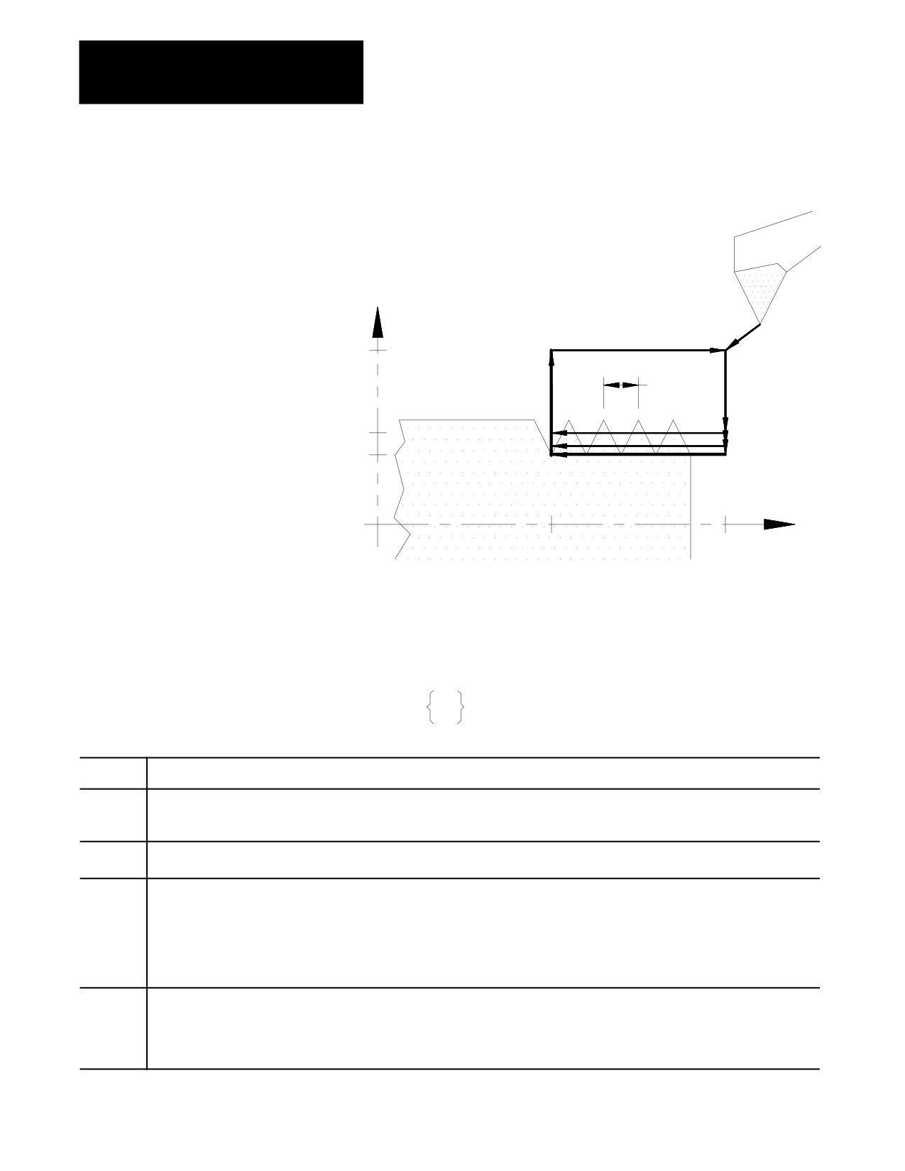
Example 25.5
G21 Straight Thread Cutting Cycle
G00X10.Z10.;
Rapid to the start point of the thread cutting cycle. This should be
a point that allows a straight, rapid, X move to the depth that the
thread is cut to.
S500.M03;
Starts the spindle turning at 500 RPM in the clockwise direction.
G21X4.8Z5.F.5;
This block makes a thread cutting pass with a lead of .5 and
return the cutting tool to the start point of the thread cutting cycle
(X10 Z10).
X4.5;
This block repeats the G21 thread cutting block using a new
depth of cut to 4.5.
X4.3;
This block repeats the G21 thread cutting block using a new
depth of cut to 4.3.
G00;
This block cancels the G21 thread cutting mode.
25-17
Chapter 25
Thread Cutting
Figure 25.12
Results of G21 Straight Thread Cutting Example
X
10.0
0.5 lead
4.8
4.3
Z
5.0
10.0
Taper Thread Cutting
This format is for programming a single pass tapered threading cycle:
G21X__Z__I__ F__ ;
E
Where :
Is :
X
This parameter is the end point of the thread cutting move in the X axis. This parameter may be an incremental or absolute and radius
or diameter value. This is the depth that the X axis moves to before starting the thread cutting pass. This value may be replaced in any
block following the G21 block while the G21 mode is active.
Z
This parameter is the end point of the thread cutting pass in the Z axis. This parameter may be an incremental or absolute value.
Z parameters are always entered as radius values.
E F
This parameter may be entered by using either an E- or F-word. It represents the thread lead along the axis with the largest
programmed distance to travel to make the thread cut. It is mandatory when cutting any threads.
If the E-word is programmed, its value (sign ignored) is equal to the number of threads per inch or inches per thread (determined in
AMP) regardless of whether inch or metric mode is active at the time.
If the F-word is programmed, its value (sign ignored) is the thread lead in inches per revolution or millimeters per revolution, depending
on the mode in which the control is operating.
I
This is the change in radius of the thread (on the X axis) that the threading pass makes as it reaches the end point of the thread cutting
pass. The end point is the X position programmed with the X-word. I is an incremental, signed distance (+ or -) added to the X
parameter to determine the start point of the threading pass on the X axis. If a chamfer is being cut at the end of the thread cutting
pass, it does not affect the value programmed here. This parameter should be entered as if no chamfer was being cut. I parameters are
always entered as radius values regardless of the current mode. I is always an incremental value regardless of the current mode.
25-18
Chapter 25
Thread Cutting
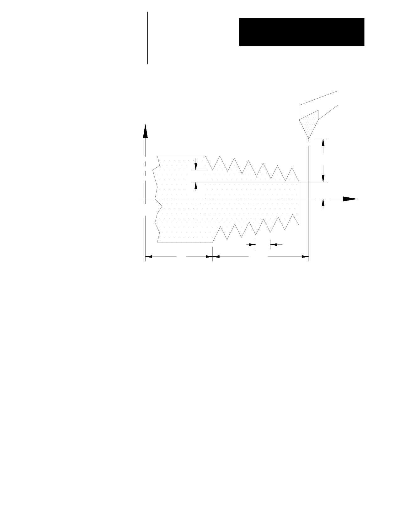
Figure 25.13
G21 Taper Thread Cutting Parameters
X
X Inc.
I
X Abs.
Z
F
Z
Z
Abs.
Inc
When this cycle is executed:
1.
The cutting tool rapids to the depth programmed with the X-word
added to the I value.
2.
The thread cutting pass is made to the position programmed with the
X- and Z-words using a feedrate that generates the required lead
programmed with the F- or E-word. As the tool moves along this
threading pass, the taper distance programmed with the I parameter is
interpolated along the X axis.
Important: If the Thread Chamfering feature was enabled before the cycle
began execution, the control performs a chamfer before reaching the
programmed Z position. The chamfer angle and length of are set in AMP.
3.
The cutting tool is retracted away from the part at a rapid feedrate to
the X axis position prior to the G21 block.
25-19
Chapter 25
Thread Cutting
4.
The cutting tool is returned along the Z axis at a rapid feedrate to the
Z axis position prior to the G21 block.
5.
Program execution continues on to the next block.
G21 is modal. Following passes need to contain only a new value for the
infeed (X value). The other parameters programmed in the G21 block
remains in effect.
25.6
The G78 multipass threading routine can be programmed to cut parallel,
face, or tapered fixed lead threads (variable lead threads may only be cut
O.D. & I.D. Multipass
using a G34 block). This routine performs a predetermined series of
Threading Routine (G78)
threading steps designated by a single program block. The G78 block
contains all of the necessary information to cut the complete thread. When
executed, the routine makes multiple passes over the thread until the
programmed root depth is reached. The control automatically generates all
threading passes necessary to reach the programmed root depth.
In effect, with the exception of the different infeed types, the multipass
threading routine is executed as if many G21 single pass threading cycles
were being executed. The key difference between the two features (aside
from infeed types) is that the multiple pass cycle only requires one block to
do the job of many single pass threading blocks. The G78 multipass
threading routine is a non-modal G-code (unlike G21). This routine is
executed only when a block contains a G78.
A finishing pass is also available with the multipass threading routine.
The size of the finishing pass, and whether a finishing pass is performed at
all, is determined by the system installer in AMP. If a finishing pass is
made, it is typically to improve final thread finish by removing a
significantly smaller amount of material with the last pass executing across
the thread by the G78 routine.
The two different chamfering features (threading retract and threading
chamfer) described in section 25.1 may also be used with this multipass
thread cutting routine. The parameters to enable these and to determine
their angle and length are set in AMP. The thread chamfer feature must
also be enabled through PAL.
The conditions to be satisfied to execute this thread cutting routine are
described in section 25.1, thread cutting considerations.
25-20
Chapter 25
Thread Cutting
Programming Multipass Thread Cutting
Before programming the G78 threading routine, the cutting tool must be
positioned to the point from which the routine is to be executed. This point
is the end-point of each complete cycle of the threading routine’s
execution.
Use this format to program a multipass thread cutting routine:
G78X__Z__K__D__ F__ A__P__I__;
E
Where :
Is :
X:
This parameter is the coordinate value of the root (depth) of the thread. If
programming a tapered thread, it is the coordinate value to be attained at the end
of the last threading pass (assume there is no chamfer cut at the end of the
pass). X values may be entered as a radius or a diameter value. X may also be
programmed as an incremental or absolute value.
Z:
This parameter is the Z coordinate value of the end of the thread cutting pass. Z
parameters are always entered as a radius value regardless of the current mode.
Z may also be programmed as an incremental or absolute value.
K:
This parameter is an unsigned value (always programmed as positive). It
programs the distance from the thread root (as determined by the X parameter to
the top of the thread. K is always programmed as a radius value.
D:
This parameter programs the depth of cut (designated in radius) for the first pass.
It is an unsigned value (always programmed as positive). The depth of following
passes is determined by this value and the type of infeed selected with the P
parameter.
A:
This parameter programs the angle of the tool tip. It must be entered as an
integer value from 0 to 120 (corresponding to 0-120 degrees). Not programming
a value for A is the same as A0. A0 would be the same as a plunge type infeed.
The value entered here determines the angle that the infeed moves makes,
which also determines the final thread angle. See the tool infeed section that
follows for details.
P:
This parameter determines the tool infeed. It must be entered as an integer
value from one to four. See the tool infeed section that follows for details.
E,F:
This parameter may be entered by using either E or F for the thread lead
(as in G33).
If the E-word is programmed, its value (always unsigned) is equal to the number
of threads per inch or inches per thread (determined in AMP) regardless of
whether inch or metric mode is active at the time.
If the F-word is programmed, its value (always unsigned) is the thread lead in
inches per revolution or millimeters per revolution, depending on the mode in
which the control is operating.
I
This is the change in radius of the thread (on the X axis) that the threading pass
makes as it reaches the end-point of the thread cutting pass. The end-point is
the X position programmed with the X-word. I is an incremental, signed distance
(+ or -) added to the X parameter to determine the start-point of the threading
pass on the X axis. If a chamfer is being cut at the end of the thread cutting
pass, it does not affect the value programmed here. This parameter should be
entered as if no chamfer were being cut. I is always an incremental value
regardless of the current mode. This parameter is always entered as a radius
value regardless of the current mode.
25-21
Chapter 25
Thread Cutting
If a straight thread is desired:
enter a value of zero for this parameter
or
do not program the I-word in the block
The control performs threading in either radius or diameter mode. Be
aware that X values entered as a radius or a diameter value when entered.
Z, I, K, and D, parameters are always entered as radius values regardless of
the current mode. X and Z may also be programmed as incremental or
absolute values. K, D, and I are always programmed as incremental values
regardless of the current mode.
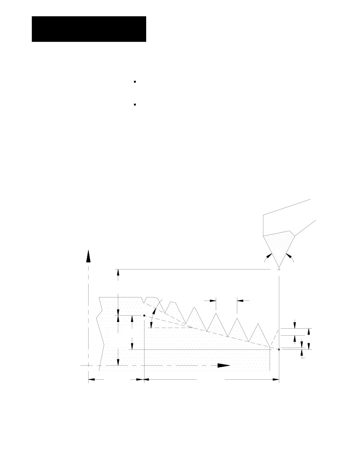
Figure 25.14 illustrates these parameters.
Figure 25.14
Multipass Thread Cutting Parameters
X
A
X inc.
Pullout angle
1/E or 1/F
D
I
K
X abs.
Finishing
Z
allowance
Z abs.
Z inc.
25-22
Chapter 25
Thread Cutting
Tool Infeed
This multipass threading routine provides 4 different types of cutting tool
infeed determined by a P-word in the threading block. These different
infeeds are provided to allow operation with different types of cutting tools
and materials. These different infeed types all move the end-point of the
cutting tool when infeeding an amount referenced from the infeed
reference point.
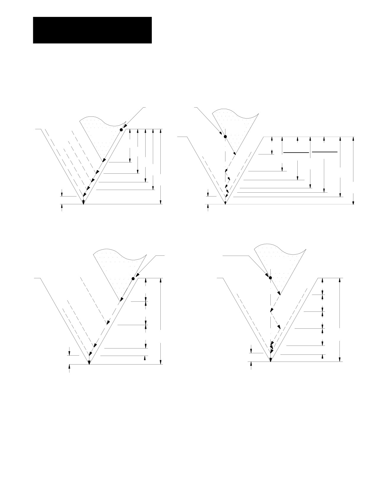
P1 - Constant cutting volume, angular infeed along thread face. A
constant amount of material is removed in each pass (except possibly the
last few passes). The last few passes may reach the minimum infeed
amount set in AMP by the system installer. If the depth of cut is smaller
than the minimum depth of cut set in AMP, it is increased to equal that
minimum depth of cut. Only one edge of the cutting tool removes
material.
P2 - Constant cutting volume, zigzag infeed. With this parameter, the
control alternates the cutting edge of the tool after every pass. The amount
of material that is removed is constant every two passes.
Important: If the user programs one pass, the control halves the
programmed depth and makes two passes. Because of this, the number of
passes programmed must always be even; and the depth of the pass cannot
be too small. If it is too small, the cutting tool may only burnish the part,
instead of cutting it.
To prevent burnishing, the system installer can program in AMP a
minimum depth of cut. If the user then enters a depth of cut smaller than
the minimum depth of cut in AMP, the entered value is disregarded, and
the value in AMP replaces it.
P3 - Constant depth of cut, angular infeed along thread face. This method
is the same as P1, except that the cutting depth is kept constant with each
pass, and there is no minimum infeed applied. Only one edge of the
cutting tool removes material.
P4 - Constant depth of cut, zigzag infeed. This method is the same as P2
except that the cutting depth is kept constant for each pass, and there is no
minimum infeed applied. Each edge of the cutting tool removes material
on alternate passes.
25-23
Chapter 25
Thread Cutting
Figure 25.15
Multipass Thread Cutting Infeed Parameters
P1
Infeed Reference
P2
Single edge
Point
Double edge
cutting
cutting
Cutting
Cutting
tool
tool
D
D÷2÷2
D(÷2+÷4)
D(÷4+÷6)
D÷2
2
2
D÷2
D÷3
D÷4
D÷4
D÷6
K
K
Finishing
Finishing
allowance
allowance
P3
Infeed Reference
P4
Single edge cutting
Point
Cutting
Double edge
Cutting
tool
cutting
tool
D
D
D
D
Infeed Reference
Point
D
D
K
D
K
D’
D’
Finishing
Finishing
allowance
allowance
D’is the remaining material to reach
D’is the remaining material
K -- finish allowance. Note 2 equal
to reach K -- finish allowance.
passes are made equal to half D’
25-24
Chapter 25
Thread Cutting
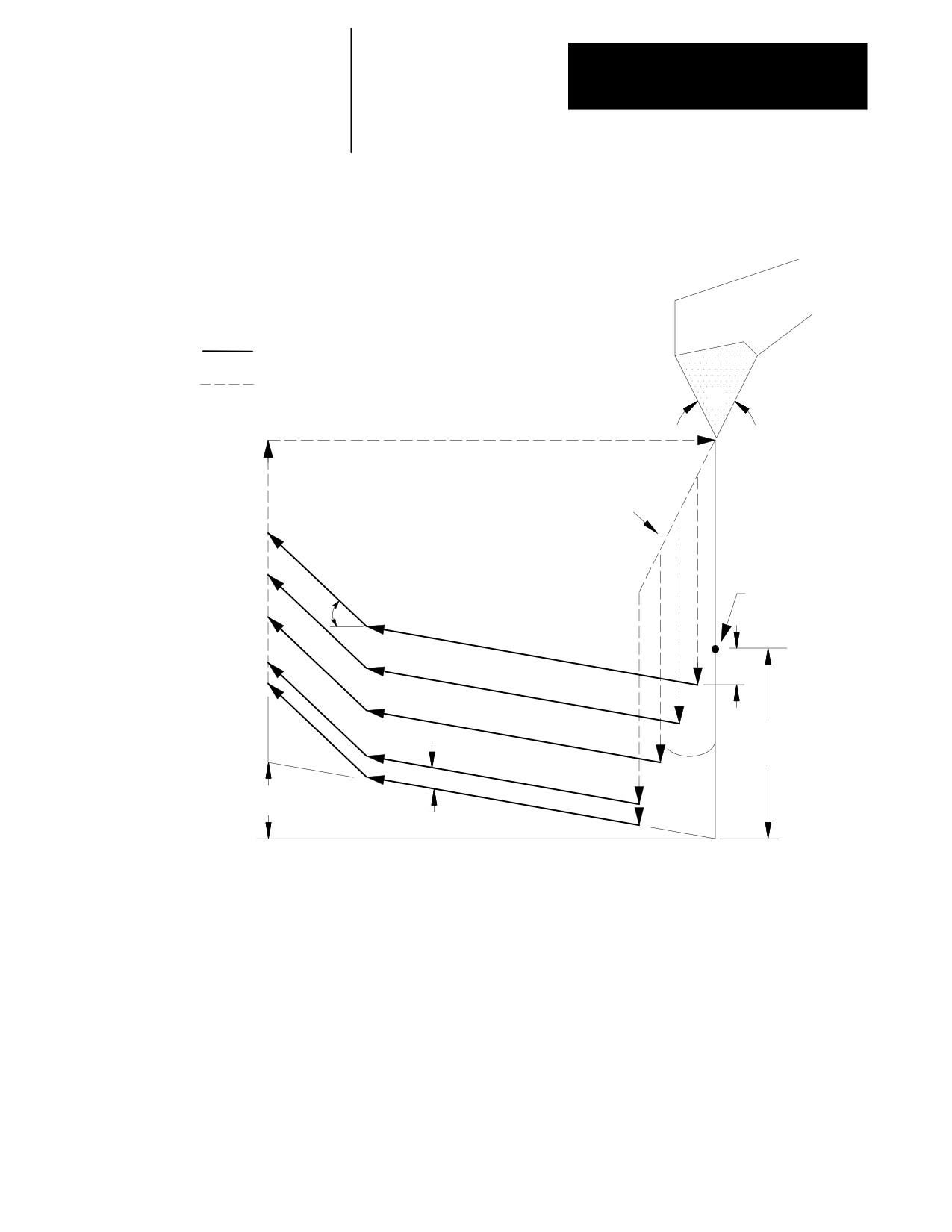
Figure 25.16
Sample Tool Paths for Multipass Threading Cycle (assumes P3)
Threading Moves
Rapid Moves
A
These distances are
determined by P-word
Infeed Reference
Pullout angle
Point
D
K
A/2
I
Finishing
allowance
END OF CHAPTER
25-25
Chapter
26
Drilling Cycles
26.0
This chapter covers the G-word data blocks in the drilling cycle group.
The operations of the drilling cycles are explained on these pages:
Chapter Overview
Topic:
Page:
Drilling cycles
26-1
Positioning and Hole Machining Axes
26-4
Parameters
26-7
Drilling Cycle Operations
26-8
Altering Drilling Cycle Operating Parameters
26-38
Fixed Drilling Cycle Examples
26-40
WARNING: The cycles described in this chapter can be used
with live tooling. This application however requires proper
PAL control of the spindle, especially in cycles that perform
spindle orients or change the spindle rotation direction. Failure
to do this can result in injury to personal or damage to
equipment.
26.1
Drilling cycles, sometimes referred to as canned cycles or auto cycles,
repeat a series of basic machining operations, such as boring, drilling, or
Drilling Cycles
tapping. These operations, designated by a single-block command, usually
consist of a fixed series of steps that are dependent on the type of
machining application.
For this chapter, as well as this manual, assume that the Z axis is the hole
machining axis. The hole machining axis is established by the system
installer.
If you are using a dual-processing system, refer to chapter 30 for more
details about drilling fixed cycles for your system.
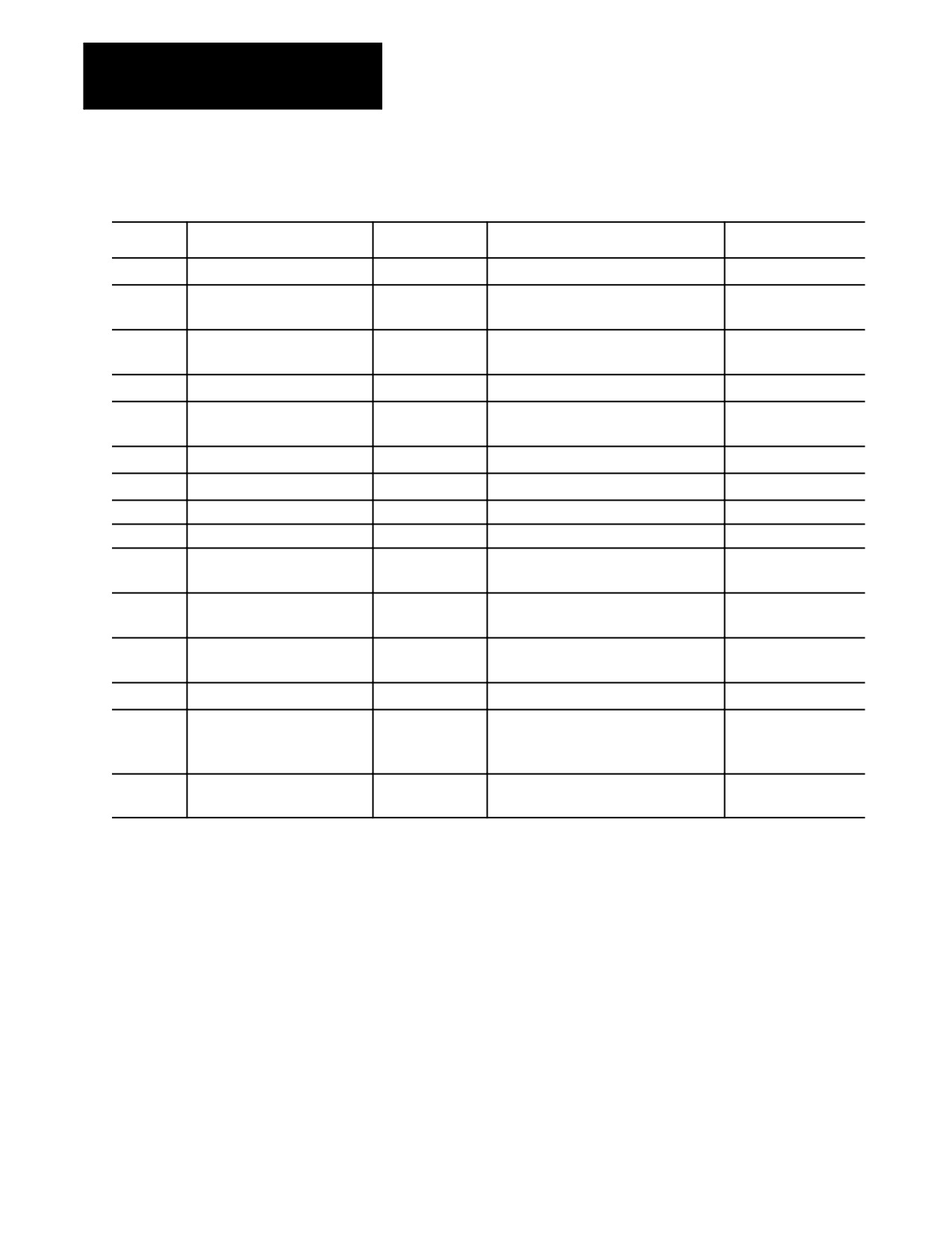
The control provides the drilling cycles shown in Table 26.A.
26-1
Chapter 26
Drilling Cycles
Table 26.A
Drilling Cycles
G-code
Application
Tool Movement
Operation At Hole Bottom
Retraction Movement
G80
Cancel Or End Fixed Cycle
N/A
N/A
N/A
G81
Drilling Cycle,
Feed
Retract
Rapid Traverse
No Dwell/Rapid Out
G82
Drilling Cycle,
Feed
Dwell / Retract
Rapid Traverse
Dwell/Rapid Out
G83
Deep Hole Drilling Cycle
Intermittent Feed
Retract
Rapid Traverse
G83.1
Deep Hole Peck
Intermittent Feed
Retract
Rapid Traverse
Drilling Cycle with Dwell
G84
Right-Hand Tapping Cycle
Feed
Spindle or Live Tool Reversed / Retract
Feed
G84.1
Left-Hand Tapping Cycle
Feed
Spindle or Live Tool Reversed / Retract
Feed
G84.2
Right-Hand Solid-Tapping Cycle
Feed
Spindle or Live Tool Reversed / Retract
Feed
G84.3
Left-Hand Solid-Tapping Cycle
Feed
Spindle or Live Tool Reversed / Retract
Feed
G85
Boring Cycle,
Feed
Retract
Feed
No Dwell/Feed Out
G86
Boring Cycle,
Feed
Spindle or Live Tool Stop / Retract
Rapid Traverse
Tool Stop/Rapid Out
G86.1
Boring Cycle,
Feed
Orient Spindle or Live Tool Stop / Retract
Rapid Traverse
Tool Shift
G87
Back Boring Cycle
Feed
Oriented Spindle or Live Tool Stop / Retract
Rapid Traverse
G88
Boring Cycle
Feed
Dwell / Retract
Manual/Rapid Traverse
Spindle or Live Tool Stop / Retract
Spindle or Live Tool Stop/
Manually Out
G89
Boring Cycle,
Feed
Dwell/Retract
Feed
Dwell/Feed Out
26-2
Chapter 26
Drilling Cycles
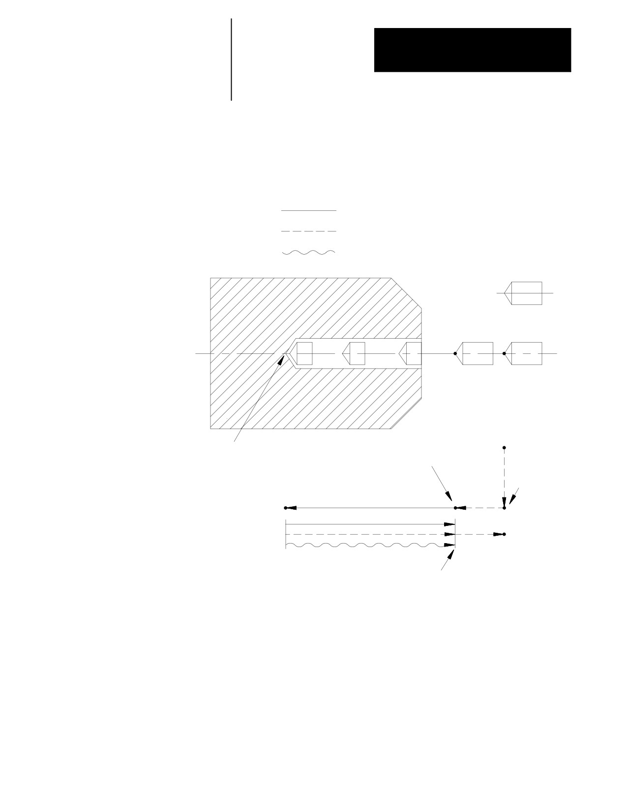
In general, drilling cycles consist of the following operations (see
Figure 26.1):
Figure 26.1
Drilling Cycle Operations
Cutting feed
Rapid feed
Manual operation
R point level
Initial point
level
Hole bottom
Rapid feed to
R point level
Positioning to
initial point
Machining
Operations at hole bottom
Rapid return to
initial point level
Return to R
point level
The system installer determines if the positioning to initial point is always
a rapid move, or if it is necessary to program a G00 or G01 to select a
mode. This manual assumes rapid positioning.
26-3
Chapter 26
Drilling Cycles
26.2
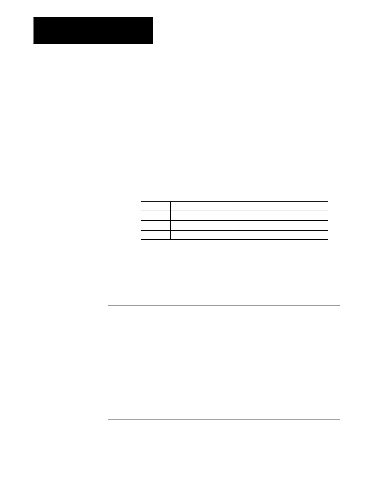
This section assumes that the programmer can determine the hole
machining axis using the plane select G-codes (G17, G18, G19). Refer to
Positioning and Hole
the system installer’s documentation to make sure that a specific axis has
Machining Axes
not been selected in AMP to be the hole machining axis.
G-codes G17, G18, or G19 determine the plane, the hole machining axis,
and the positioning axes. The two axes that define the selected plane are
used as positioning axes. The axis perpendicular to the plane is the hole
machining axis.
Table 26.B assumes a specific plane definition. Refer to the system
installer’s documentation for the plane definitions on your system.
Table 26.B
Plane Selection vs Machining Axis
Plane
Hole Machining Axis
Positioning Axes
XU (G17)
Z axis or its parallel axis
X and U axes or their parallel axes
ZX (G18)
U axis or its parallel axis
Z and X axes or their parallel axes
UZ (G19)
X axis or its parallel axis
U and Z axes or their parallel axes
Example 27.1 shows you how to change the hole machining axis to a
parallel axis. Prior to changing the hole machining axis, a G80 should be
executed to cancel any active milling mode.
Example 27.1
Altering the Machining Axis to a Parallel Axis
Program Block
Comment
The W axis is parallel to the Z axis.
G17;
XU plane active
G81X ___ U ___ ;
Drilling cycle, Z is the hole
machining axis
G80;
Cancel drilling fixed cycle
mode
G81X ___ U ___ W ___;
Drilling cycle, W is the hole
machining axis
The plane selection codes (G17, G18, and G19) can be included in the
drilling fixed cycle block, or can be programmed in a previous block.
26-4